


GCM102(/M)
30 mm Cage System Mount
For Small Beam Diameter Galvos
User Guide
Original Instructions
HA 0371T

GCM102(/M) 30 mm Cage System Mount for GVSx02 Series Galvos
Contents
Chaper 1 Overview ..................................................................................................... 1
1.1 Description ......................................................................................... 1
Chaper 2 Safety .......................................................................................................... 2
2.1 Safety Information .................. ............................ ............................ ... 2
Chaper 3 Installation .................................................................................................. 3
3.1 Installing the Galvo Motors ............................................................... 3
3.2 Fitting the Optics and Adapters ....................................................... 8
3.3 Using the Cage Mount with Other Equipment ............................... 11
3.3.1 Mounting to a 1.5” Diameter Post ......................................................... 11
3.3.2 Mounting to 66 mm Rail Components .................................................. 12
Chaper 4 Thorlabs Worldwide Contacts ................................................................ 14

Chapter 1 Overview
Chapter 1 Overview
1.1 Description
The GCM102(/M) cage system adapter is used to mount the GVSX02 dual-axis galvo
systems into a 30 mm cage system. The galvo motors can be fitted and aligned
without dismantling the mount
On the beam input side, the mount features SM1 and SM05 threads for mounting lens
tubes. The output side is th readed SM2, which can be converted to M25 x 0.75 by
fitting the GCMA1 or SM2A33 adapters. The mounting face features an array of M6,
M4 and M3 (1/4-20, 4-40 and 8-32 UNC) threaded holes for use in mounting to our
range of 1.5 OD posts, and XT66 construction rails.
Note: The input and output beams are on different planes. Cage systems should be
adapted accordingly.
Fig. 1.1 GCM102 Cage Mount, post mounted with lens and cage rods fitted
Rev B Jan 2018
Page 1

GCM102(/M) 30 mm Cage System Mount for GVSx02 Series Galvos
Chapter 2 Safety
2.1 Safety Information
For the continuing safety of the operators of this equipment, and the protection of the
equipment itself, the operator should take note of the Warnings, Cautions and Notes
throughout this handbook and, where visible, on the product itself.
The following safety symb ols may be used throughout the handbook and on the
equipment itself.
Warning: Risk of Electrical Shock
Given when there is a risk of injury from electrical shock.
Warning
Given when there is a risk of injury to users.
Caution
Given when there is a risk of damage to the product.
Note
Clarification of an instruction or additional information.
Page 2 ETN032532-D02

Chapter 3 Installation
Removing the blanking plugs
Loosening the motor clamp bolts
Chapter 3 Installation
3.1 Installing the Galvo Motors
1) Using a 2.5 mm hex key, loosen the pinch bolts on the existing mount, and remove
the motor/mirror assemblies. Leave the spacers fitted to the motors and retain the
insulating film for later use. Take care not to touch the mirror surfaces.
2) Once removed, check that the the rmal insulation film is u ndamaged. Damaged
material should be discarded. Replacement film is supplied with the cage mount.
Fig. 3.1 Removing Motor/Mirror Assemblies
3) Using a 3 mm (1/8”) hex key, remove the blanking plugs from the body of the
GCM102(/M) Cage Mount, to gain access to the motor clamp.
Using a 2mm ( 5/64”) hex key, loosen the clamp bolts.
Fig. 3.2 Loosening the motor clamp bolts
Rev B Jan 2018
Page 3

GCM102(/M) 30 mm Cage System Mount for GVSx02 Series Galvos
4) Position the cage mount assembly as shown in Fig. 3.3 and using a 2 mm (5/64”)
hex key, remove the screws securing the small gasket cover. Remove the gasket
cover, then remove the screws securing the large gasket cover.
Fig. 3.3 Removing the Gasket Covers
5) Position the cage mount assembly as shown in Fig. 3.4 and using a 2 mm (5/64”)
hex key, remove the remain ing screws se curing the large gasket cover, then
remove the gasket cover.
Fig. 3.4 Removing the Gasket Covers
6) Position the cage mount as shown in Fig. 3.5, with the fixed side of the gasket to
the left. Slide the large spacer underneath the gasket then pull the gasket over the
Page 4 ETN032532-D02

Chapter 3 Installation
spacer such that it pushes through the hole in the gasket, and the gasket fits tights
around the sides of the spacer..
Fig. 3.5 Inserting the Large Spacer
7) Reposition the cage mount as shown in Fig 3.6, and in sert the small spa cer
underneath the gasket. Pull the gasket over the spacer such that it pushes through
the hole in the gasket, and the gasket fits tights around the sides of the spacer.
Fig. 3.6 Inserting the Small Spacer
Rev B Jan 2018
Page 5
GCM102(/M) 30 mm Cage System Mount for GVSx02 Series Galvos
Detail A
Detail B
8) Roll up the thermal insulation film into a small tube shape and insert into the motor
mounting holes as shown below. Ensure the film is pushed fully into the hole.
Fig. 3.7 Fitting the thermal insulation film
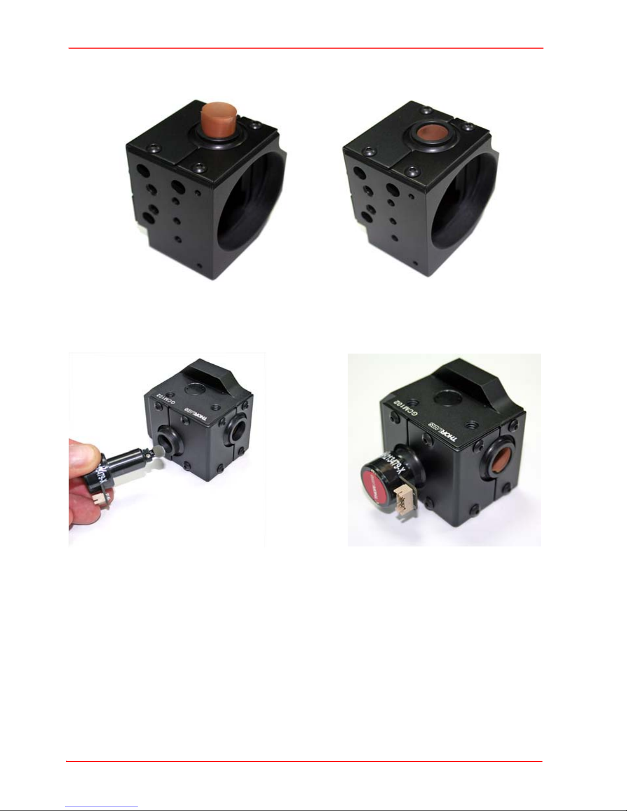
9) Place the cage adapter body on the worksurface as shown below, with the
engraving on the left, and the large open face facing away and to the right.
Fig. 3.8 Inserting the Motors
10) Identify the X-Axis motor assembly. This is the motor with the smallest mirror and
the serial number label has a suffix ‘-X’.
11) Insert the motor into the lower mount on the left hand side - see Fig. 3.8 Detail A.
Caution. Ensure that the wide spacer and the thermal insulation detailed
previously are fitted. The X-axis mirror will be misaligned without the wide
spacer. The clamp pinch bolts will not tighten sufficiently without the
thermal insulation material.
Gently twist the motor bod y as it is pu shed into the clamp, ta king care not to
damage the thermal insulation material.
Page 6 ETN032532-D02

Chapter 3 Installation
12) Ensure that the narrow plastic spacer removed at item (1) is fitted to the remaining
mounting hole, then insert the Y-axis motor into the upper mount on the right hand
side- see Fig. 3.8 Detail B.
Caution. Ensure that the thermal insulation detailed at item (4) is fitted. The
clamp pinch bolts will not tighten sufficiently without this material.
Gently twist the motor bo dy as it i s pushed into the clamp, taking care not to
damage the thermal insulation material.
13) Ensure that the motors are pushed fully into the moun ting holes, then turn the
motors to be aligned as shown in Fig. 3.9. The left hand (X-Axis) motor connector
should point to the right hand side. The right hand (Y-Axis) connector should point
downwards. Check through the large open face that the mirror alignment is as
shown below.
Fig. 3.9 Aligning the motors
14) Using a 2 mm (5/64”) hex key, tighten the pinch bolts on the clamps as shown below.
Fig. 3.10 Tightening the pinch bolts
15) Using a 3 mm (1/8”) hex key, refit the blanking plugs.
16) The system is now ready to be m ounted into a cage system, however further
adjustment of the motor posi tions may be nece ssary to fine tune the mirror
alignment within the application.
Rev B Jan 2018
Page 7
GCM102(/M) 30 mm Cage System Mount for GVSx02 Series Galvos
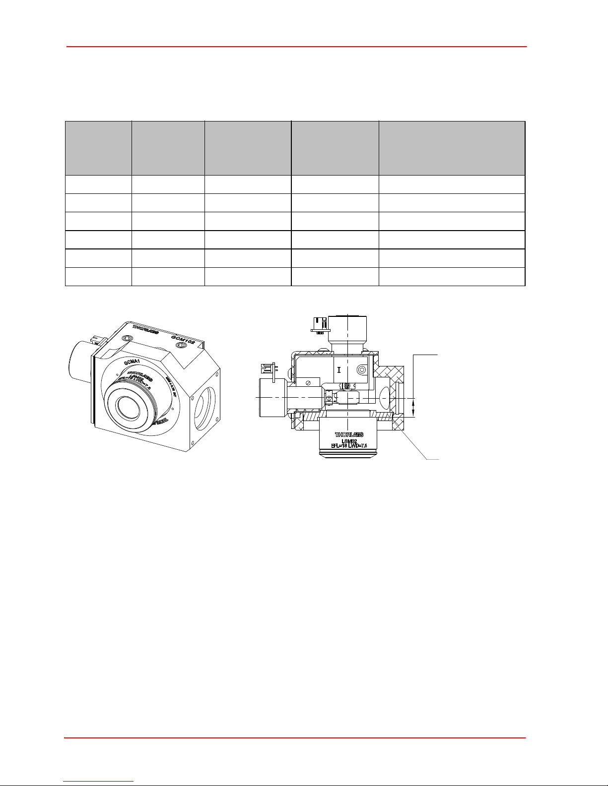
Distance from
input axis to
reference face
of lens
11.0 mm (0.43”)
GCMA1
screwed down to
bottom face
3.2 Fitting the Optics and Adapters
A range optics can be fitted to the GCM102(/M) using various adapters as detailed
below.
Scan
Optic Thread
Distance
(mm)
LSM02 M25 x 0.75 16 3 GCMA1
LSM03 M25 x 0.75 19 6 GCMA1 (reverse fitted)
LSM04 M25 x 0.75 19 6 GCMA1 (reverse fitted)
LSM03-VIS M25 x 0.75 29 16 SM2A33 and SM2L03
LSM05 SM2 75 62 SM2L20
CLS-SL SM2 58 46 SM2L05 and SM2V05
Distance from
start of SM2
thread (mm)
Adapter Required
Page 8 ETN032532-D02
Fig. 3.11 Fitting the LSM02
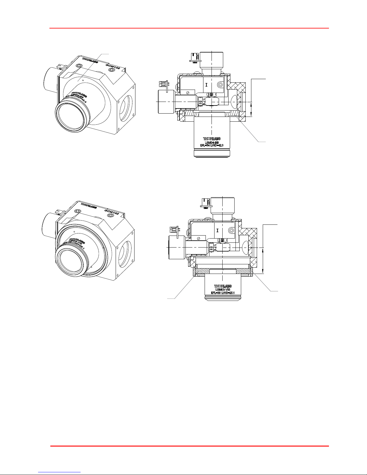
Fig. 3.12 Fitting the LSM03 and LSM04
Distance from
input axis to
reference face
of lens
14.0 mm (0.55”)
GCMA1 inverted
and screwed down
to bottom face
GCMA1 inverted
Distance from
input axis to
reference face
of lens
24.3 mm (0.96”)
SM2L03
screwed down
to bottom face
SM2A33
Chapter 3 Installation
Rev B Jan 2018
Fig. 3.13 Fitting the LSM03-VIS
Page 9

GCM102(/M) 30 mm Cage System Mount for GVSx02 Series Galvos
Distance from
input axis to
reference face
of lens
70.1 mm (2.76”)
SM2L20
screwed
down to
bottom face
Distance from
input axis to
reference face
of lens
53.1 mm (2.09”)
SM2V05 screwed
down around 5 mm
Lock Nut
SM2L05 screwed
down to SM2V05
Fig. 3.14 Fitting the LSM05
Page 10 ETN032532-D02
Fig. 3.15 Fitting the CLS-SL

Chapter 3 Installation
29.0 mm
[1.14”]
63.8 mm
[2.51”]
C1511
Mounting Clamp
M6 [1/4-20] Cap Screw
6.0 or 10.0 [1/4” or 3/8”] Long
M4 [8-32] Cap Screw
6.0 mm [1/4”] Long
M4 [8-32] Cap Screw
6.0 mm [1/4”] Long
1.5” Dia Post
(e.g. DP8A)
Mounting Option 1
Mounting Option 2
3.3 Using the Cage Mount with Other Equipment
The GCM102(/M) can be used in conjunction with various posts, rails and accessories
available from Thorlabs as follows.
3.3.1 Mounting to a 1.5” Diameter Post
Fig. 3.16 Mounting the GCM102 to a 1.5” Diameter Post
Rev B Jan 2018
Page 11

GCM102(/M) 30 mm Cage System Mount for GVSx02 Series Galvos
36.0 mm
[1.44”]
69.6 mm
[2.74”]
XT66
Construction Rail
M6 [1/4-20] Cap Screw
6.0 or 8.0 mm [1/4” or 5/16”] Long
M3 [4-40] Cap Screws, Qty 2
6.0 or 8.0 mm [1/4” or 5/16”] Long
XT66P2
Rail Carriage
3.3.2 Mounting to 66 mm Rail Components
Fig. 3.17 Mounting the GCM102 to an XT66 Construction Rail
Page 12 ETN032532-D02

Chapter 3 Installation
XT66
Construction Rail
SH6M10LP [SH25LP38]
M6 [1/4-20] Low Profile Channel Screws
XT66RC
Pivot Platform
46.1 mm
[1.82”]
79.2 mm
[3.12”]
6.5 mm
[0.26”]
Fig. 3.18 Mounting the GCM102 to an XT66RC Pivot Platform
Rev B Jan 2018
Page 13

Chapter Thorlabs Worldwide Contacts
USA, Canada, and South America
Thorlabs, Inc.
56 Sparta Avenue
Newton, NJ 07860
USA
Tel: 973-300-3000
Fax: 973-300-3600
www.thorlabs.com
www.thorlabs.us (West Coast)
Email: sales@thorlabs.com
Support: techsupport@thorlabs.com
Europe
Thorlabs GmbH
Hans-Böckler-Str. 6
85221 Dachau / Munich
Germany
Tel: +49-(0) 8131-5956-0
Fax: +49-(0) 8131-5956-99
www.thorlabs.de
Email: europe@thorlabs.com
France
Thorlabs SAS
rue des Côtes
109,
78600 Maisons-Laffitte
France
Tel: +33 (0) 970 444 844
Fax: +33 (0) 825 744 800
www.thorlabs.com
Email: sales.fr@thorlabs.com
UK and Ireland
Thorlabs Ltd.
1 Saint Thomas Place
Ely B7 4EX
Great Britain
Tel: +44 (0) 1353-654440
Fax: +44 (0) 1353-654444
www.thorlabs.com
Email: sales.uk@thorlabs.com
Support: techsupport.uk@thorlabs.com
Scandinavia
Thorlabs Sweden AB
Bergfotsgatan 7
431 35 Mölndal
Sweden
Tel: +46-31-733-30-00
Fax: +46-31-703-40-45
www.thorlabs.com
Email: scandinavia@thorlabs.com
Brazil
Thorlabs Vendas de Fotônicos Ltda.
Rua Riachuelo, 171
São Carlos, SP 13560-110
Brazil
Tel: +55-16-3413 7062
Fax: +55-16-3413 7064
www.thorlabs.com
Email: brasil@thorlabs.com
Japan
Thorlabs Japan, Inc.
3-6-3, Kitamachi,
Nerima-ku, Tokyo 179-0081
Japan
Tel: +81-3-6915-7701
Fax: +81-3-6915-7716
www.thorlabs.co.jp
Email: sales@thorlabs.jp
Page 14
China
Thorlabs China
Room A101, No. 100, Lane 2891
South Qilianshan Road
Putuo District
Shanghai
China
Tel: +86 (0) 21-60561122
Fax: +86 (0) 21-32513480
www.thorlabschina.cn
Email: chinasales@thorlabs.com

www.thorlabs.com
 Loading...