


Manual Fiber
Polarization Controllers
User Guide

Manual Fiber Polarization Controllers
Table of Contents
Chapter 1 Warning Symbol Definitions ..................................... 1
Chapter 2 General Description ................................................... 2
2.1. 3‐PaddleFiberPolarizationControllers....................3
2.2. Miniature2‐PaddleFiberPolarizationControllers....6
2.3. RecommendedNumberofLoops.............................8
Chapter 3 Setup ......................................................................... 10
3.1. LoadingtheFiber...................................................10
3.1.1. 3-Paddle Fiber Polarization Controllers ............................. 10
3.1.2. Miniature 2-Paddle Fiber Polarization Controllers ............. 11
3.2. RemovingtheFiber(AllModels)............................11
Chapter 4 Specifications........................................................... 12
4.1. 3‐PaddlePolarizationControllers...........................12
4.2. Miniature2‐PaddlePolarizationControllers..........14
Chapter 5 Regulatory ................................................................ 16
Chapter 6 Thorlabs Worldwide Contacts ................................ 17

Manual Fiber Polarization Controllers Chapter 1: Warning Symbol Definitions
Chapter 1 Warning Symbol Definitions
Below is a list of warning symbols you may encounter in this manual or on
your device.
Symbol Description
Direct Current
Alternating Current
Both Direct and Alternating Current
Earth Ground Terminal
Protective Conductor Terminal
Frame or Chassis Terminal
Equipotentiality
Rev H, September 11, 2018 Page 1
On (Supply)
Off (Supply)
In Position of a Bi-Stable Push Control
Out Position of a Bi-Stable Push Control
Caution: Risk of Electric Shock
Caution: Hot Surface
Caution: Risk of Danger
Warning: Laser Radiation
Caution: Spinning Blades May Cause Harm

Manual Fiber Polarization Controllers Chapter 2: General Description
Chapter 2 General Description
These manual polarization controllers utilize stress-induced birefringence to
alter the polarization in single mode fiber that is looped around two or three
independent spools to create two or three independent fractional wave plates
(fiber retarders). The amount of birefringence induced in the fiber is a function
of the fiber cladding diameter, the spool diameter (fixed), the number of fiber
loops per spool, and the wavelength of the light. (NOTE: The desired
birefringence is induced by the loop in the fiber, not by the twisting of the fiber
paddles). The fast axis of the fiber, which is in the plane of the spool, is
adjusted with respect to the transmitted polarization vector by manually
rotating the paddles to twist the fiber.
To transform an arbitrary input polarization state into an arbitrary output
polarization state, a combination of three paddles (a quarter-wave plate, a
half-wave plate, and a quarter-wave plate) or two paddles (quarter-wave plate
and a quarter-wave plate) is used. The retardance of each paddle may be
estimated from the following equation:
2
Here, φ is the retardance, a is a constant (0.133 for silica fiber), N is the
number of loops, d is the fiber cladding diameter, λ is the wavelength, and D
is the loop diameter. While this equation is for bare fiber, the solution for Ø900
µm jacketed fiber will be similar enough that the results for this equation can
still be used (i.e., the solution will not vary by a complete loop N for Ø900 µm
jacketed fiber).
The FPC020, FPC030, and FPC560 are empty controllers in which the user
can install a fiber of their choice. The rest of our fiber polarization controllers
have fiber pre-installed to optimize the polarization control at common
wavelengths. These controllers can also be customized using the information
provided in Sections 2.1 through 0.
Page 2 1167-D02

Manual Fiber Polarization Controllers Chapter 2: General Description
2.1. 3-Paddle Fiber Polarization Controllers
A 3-paddle polarization controller combines a quarter-wave plate, half-wave
plate, and quarter-wave plate in series to transform an arbitrary polarization
state into any other polarization state. The first quarter-wave plate would
transform the input polarization state into a linear polarization state. The halfwave plate would rotate the linear polarization state, and the last quarter-wave
plate would transform the linear state into an arbitrary polarization state.
Therefore, adjusting each of the three paddles (fiber retarders) allows
complete control of the output polarization state over a broad range of
wavelengths from 300 to 2100 nm. The 3-paddle polarization controllers are
available with paddles that support either Ø27 mm loops or Ø56 mm loops.
Using FPC030 as an example for the controllers with a Ø27 mm loop
diameter, a plot of calcuated retardation per paddle versus wavelength is
shown in Figure 1 for a fiber with a cladding diameter of 80 μm. For fiber with
a cladding diameter of 125 μm, the retardation per paddle versus wavelength
is shown in Figure 2.
Rev H, September 11, 2018 Page 3

Manual Fiber Polarization Controllers Chapter 2: General Description
Figure 1
Figure 2
Page 4 1167-D02

Manual Fiber Polarization Controllers Chapter 2: General Description
Figure 3 and Figure 4 show the results for Ø80 µm and Ø125 µm clad fiber,
respectively, for the FPC560 controller, which has three paddles with a loop
diameter of 56 mm. The larger loop diameter is ideal for fibers with higher
bend loss.
Figure 3
Figure 4
Rev H, September 11, 2018 Page 5

Manual Fiber Polarization Controllers Chapter 2: General Description
2.2. Miniature 2-Paddle Fiber Polarization Controllers
The 2-paddle polarization controllers use two quarter-wave plates to transform
an arbitrary polarization state into any other polarization state. In this
configuration, however, the control of the polarization will be coupled between
the two paddles. These controllers allow complete control of the output
polarization state over a broad range of wavelengths (300 to 2100 nm).
The retardation per paddle is a function of loop number and the cladding
diameter of the fiber if the loop diameter is fixed. The retardation, in radians,
is plotted for 1, 2, 3, and 4 loops per paddle for a fiber with cladding diameters
of 80 µm and 125 μm (Figure 5 and Figure 6). Due to its small size, the
FPC020 cannot accommodate more than 4 loops per paddle.
Page 6 1167-D02

Manual Fiber Polarization Controllers Chapter 2: General Description
Figure 5
Figure 6
Rev H, September 11, 2018 Page 7

Manual Fiber Polarization Controllers Chapter 2: General Description
2.3. Recommended Number of Loops
The retardation of multi-order (including zero order) quarter-wave plate is
given by the following equation:
2 1
where m is an integer. Similarly, the retardation of multi-order (including zero
order) half-wave plate is given by:
2 1
See the table below for several solutions to the equations
2
Quarter-Wave
Order m
Zero 0
1st 1
2nd 2
3rd 3
4th 4
5th 5
Plate Retardation
2
3
2
5
2
7
2
9
2
11
2
1.57
4.71
7.85
11.00
14.14
17.28
Half-Wave Plate
Retardation
3.14
3 9.42
5 15.71
7 21.99
9 28.27
11 35.56
The retardation of each paddle should be close to any number above. The
paddle rotation sensitivity should also be taken into consideration when
determining the number of fiber loops. In creasing the number of loops
increases the sensitivity to rotation. One loop is usually too insensitive for most
applications and is rarely used.
Page 8 1167-D02
Manual Fiber Polarization Controllers Chapter 2: General Description
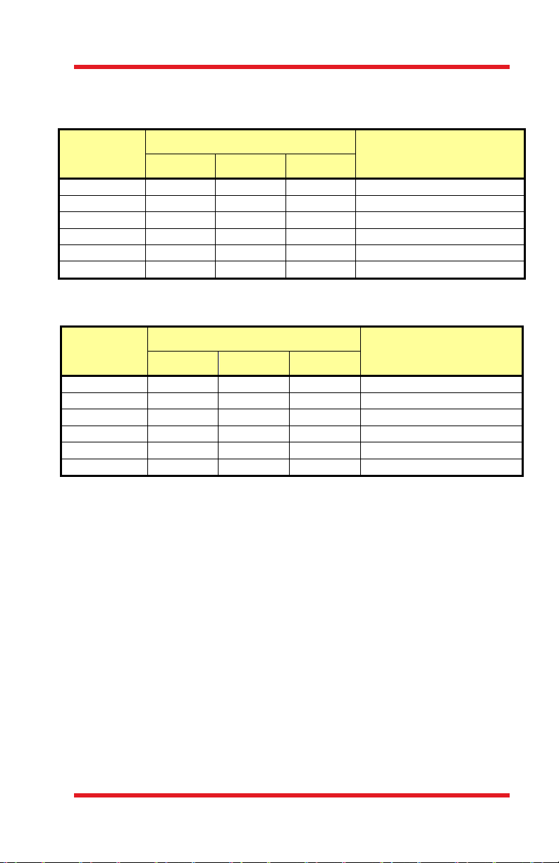
The number of recommended loops and recommended fiber for several
wavelengths is given in the following tables. These combinations come close
to the desired quarter-wave retardation:
# of Loops for ~1/4λ Retardation
Wavelength
480 nm 3 loops N/A 3 loops 460HP, S450, S460
630 nm 3 loops 2 loops 4 loops 630HP or S630
850 nm 3 loops 6 loops 2 loops 780HP, SM800-5.6
980 nm 2 loops 3 loops 2 loops 980HP, HI1060-J9, HI980-J9
1060 nm 2 loops 3 loops 2 loops 980HP, HI1060-J9, HI980-J9
1310 nm 3 loops 2 loops 3 loops SMF28e+ and CCC1310-J9
Recommended Fiber Ø18 mm Ø27 mm Ø56 mm
These combinations come close to the desired half-wave retardation:
# of Loops for ~1/2λ Retardation
Wavelength
480 nm 2 loops 3 loops 2 loops 460HP, S450, S460
630 nm 1 loop 4 loops 3 loops 630HP or S630
850 nm 1 loop 2 loops 4 loops 780HP, SM800-5.6
980 nm 4 loops 2 loops 4 loops 980HP, HI1060-J9, HI980-J9
1060 nm 3 loops 2 loops 5 loops 980HP, HI1060-J9, HI980-J9
1310 nm 2 loops 3 loops 6 loops SMF28e+ and CCC1310-J9
Recommended Fiber Ø18 mm Ø27 mm Ø56 mm
Rev H, September 11, 2018 Page 9

Manual Fiber Polarization Controllers Chapter 3: Setup
Chapter 3 Setup
3.1. Loading the Fiber
3.1.1. 3-Paddle Fiber Polarization Controllers
The FPC030 and FPC560 do not come with fiber and we recommend using
at least 2 m of fiber. The controller can accept bare fiber or a jacket up to
Ø900 µm.
1. Loosen the spool covers on each paddle. Each end of the fiber
polarization controller (FPC) also has a rectangular clamp held in place
by two phillips head screws (Figure 7). Remove one screw and loosen
the other. This should allow a jacketed fiber to be slipped into the clamp.
2. Position the Paddles horizontally so that the groove loops are facing up.
The straight parts of the grooves in the paddles should be aligned with
the grooves in the top of the paddle supports of the base.
3. Lay the fiber in one end of the FPC and continue to lay the fiber along the
grooved path, with the number of desired loops per paddle, until the fiber
is through the other end of the FPC. The fiber should be in contact with
the inside of the groove loops, but not be pulled too snug against the
groove as this will cause optical losses due to induced birefringence as
the paddles are rotated with respect to each other.
4. Make sure that the fiber is sitting in the groove inside each clamp, replace
the second screw, and gently tighten the clamp to hold the fiber in place.
NOTE: The ends of the FPC are designed to ‘clamp’ onto 900 µm
diameter protective tubing. If the fiber placed into the FPC does not have
a protective jacket, pieces of a soft material, such as foam, can be
inserted into the end clamps to prevent the fiber from loosening in the
paddles. The fiber should be held ‘gently’ enough so that the fiber is not
drawn into the FPC, but there should be minimal force applied to the fiber
such that additional birefringence is not induced.
5. Gently tighten the screws that hold the spool covers in place.
Spool Cover
Clamp
Figure 7 Top View of FPC030
Page 10 1167-D02

Manual Fiber Polarization Controllers Chapter 3: Setup
3.1.2. Miniature 2-Paddle Fiber Polarization Controllers
The FPC020 does not come with fiber and we recommend using at least 2 m
of fiber. The controller can accept bare fiber or a jacket up to Ø900 µm.
1. Position both paddles vertically and align the grooves (see Figure 8).
2. Loosen the 4-40 clamp screws (marked a in Figure 8) at each end. If you
are having problems getting the fiber into the spool, you can loosen the
4-40 screw holding the spool cover in place (b), but this should not be
necessary.
3. Lay the fiber in one end of the FPC and route the fiber along the grooved
path. Lay the desired number of loops into each paddle. End by bringing
the fiber out the other end of the FPC. Make sure to wind the fiber snuggly
against the inner wall of each spool but do not make the fiber taught.
4. Making sure the fiber is seated in the groove, tighten the clamp screws
(a) at each end. Be careful not to clamp too tightly or make the fiber too
taught as this will introduce extra loss into the fiber. Tighten the paddle
screws (b) if they were loosened.
(b)
(a)
(b)
(a)
Figure 8 Front View of FPC020
3.2. Removing the Fiber (All Models)
1. Loosen the clamp screws as described in the fiber installation
instructions.
2. Remove the paddle spool covers. For the 2-paddle polarization
controllers, use a 4-40 hex key or ball drive to loosen the screws. On the
3-paddle controllers, knobs on the screws holding the spool covers in
place allow them to be loosened by hand.
3. Remove the fiber and replace the spool covers and clamps when done.
Rev H, September 11, 2018 Page 11

Manual Fiber Polarization Controllers Chapter 4: Specifications
Chapter 4 Specifications
4.1. 3-Paddle Polarization Controllers
Item # FPC030 FPC031 FPC032
Paddle Material
Number of Paddles
Loop Diameter
Paddle Rotation
Foot Print (L x W)
Fiber
Operating Wavelength Range
Design Wavelength
b
Mode Field Diameter
Cladding Diameter
Coating Diameter
Tubing Diameter
Numerical Aperture
Loop Configuration
c
Connectors
Bend Loss
a
8.5" x 1.0" (215.9 mm x 25.4 mm)
None CCC1310-J9
N/A 1260 - 1625 nm
N/A 1310 nm
N/A
N/A 125 ± 0.7 µm
N/A 242 ± 5 µm
N/A Ø900 µm Tight Buffer
N/A 0.14
N/A 2-3-2
N/A FC/PC FC/APC
N/A ≤0.1 dB
a. Retardance varies as a function of wavelength. Refer to Chapter 2 for
more information.
b. Devices with preloaded fiber are optimized for this wavelength.
c. For polarization controllers with fiber preinstalled.
Black Delrin
3
1.06" (27 mm)
±117.5°
8.6 ± 0.4 µm @ 1310 nm
9.7 ± 0.5 µm @ 1550 nm
Page 12 1167-D02

Manual Fiber Polarization Controllers Chapter 4: Specifications
Item # FPC560 FPC561 FPC562
Paddle Material
Number of Paddles
Loop Diameter
Paddle Rotation
Foot Print (L x W )
Fiber
Operating Wavelength Range
Design Wavelength
b
Mode Field Diameter
12.5" x 1.0" (317.5 mm x 25.4 mm)
None SMF-28-J9
a
N/A 1260 - 1625 nm
N/A 1310 nm
N/A
Black Delrin
3
2.2" (56 mm)
±117.5°
9.2 ± 0.4 µm @ 1310 nm
10.4 ± 0.5 µm @ 1550 nm
Cladding Diameter
Coating Diameter
Tubing Diameter
Numerical Aperture
Loop Configuration
Connectors
Bend Loss
c
N/A 125 ± 0.7 µm
N/A 242 ± 5 µm
N/A Ø900 µm Tight Buffer
N/A 0.14
N/A 3-6-3
N/A FC/PC FC/PC
N/A ≤0.1 dB
a. Retardance varies as a function of wavelength. Refer to Chapter 2 for
more information.
b. Devices with preloaded fiber are optimized for this wavelength.
c. For polarization controllers with fiber preinstalled.
Rev H, September 11, 2018 Page 13

Manual Fiber Polarization Controllers Chapter 4: Specifications
4.2. Miniature 2-Paddle Polarization Controllers
Item # FPC020 FPC021 FPC022
Paddle Material Black Delrin
Number of Paddles 2
Loop Diameter
Paddle Rotation ±143°
Foot Print (L x W) 3.06" x 0.5" (77.72 mm x 12.70 mm)
Fiber None SM450 SM600
Operating Wavelength Range
Design Wavelength
Mode Field Diameter N/A 3.3 µm @ 488 nm
Cladding Diameter N/A 125 ± 1.0 µm
Coating Diameter N/A 245 ± 15 µm 245 µm ± 5%
Tubing Diameter N/A Ø900 µm Hytrel Tubing
Numerical Aperture N/A 0.10 - 0.14
Loop Configuration
Connectors N/A FC/APC
Bend Loss N/A <0.1 dB
b
c
a
N/A 450 - 600 nm 600 - 800 nm
N/A 488 nm 633 nm
N/A 3-3
a. Retardance varies as a function of wavelength. Refer to Chapter 2 for
more information.
b. Devices with preloaded fiber are optimized for this wavelength.
c. For polarization controllers with fiber preinstalled.
0.71
" (18 mm)
3.4 µm @ 514 nm
4.3 µm @ 633 nm
4.6 µm @ 680 nm
Page 14 1167-D02

Manual Fiber Polarization Controllers Chapter 4: Specifications
Item # FPC023 FPC024 FPC025
Paddle Material Black Delrin
Number of Paddles 2
Loop Diameter
Paddle Rotation ±143°
Foot Print (L x W) 3.06" x 0.5" (77.72 mm x 12.70 mm)
Fiber 780HP HI1060 CCC1310
Operating Wavelength Rangea 780 - 970 nm 980 - 1650 nm 1260 - 1625 nm
Design Wavelength
Mode Field Diameter
Cladding Diameter 125 ± 1.5 µm 125 ± 0.5 µm 125 ± 0.7 µm
Coating Diameter 245 ± 15 µm 245 ± 10 µm 242 ± 5 µm
Tubing Diameter Ø900 µm
Numerical Aperture 0.13 0.14
Loop Configuration
Connectors FC/APC
Bend Loss <0.1 dB
b
c
780 nm and
850 nm
5.0 ± 0.5 µm
@ 850 nm
Hytrel Tubing
4-4 2-2 3-3
0.71
" (18 mm)
980 nm 1310 nm
5.9 ± 0.3 µm
@ 980 nm
6.2 ± 0.3 µm
@ 1060 nm
Ø900 µm Tight Buffer
8.6 ± 0.4 µm
@ 1310 nm
9.7 ± 0.5 µm
@ 1550 nm
a. Retardance varies as a function of wavelength. Refer to Chapter 2 for
more information.
b. Devices with preloaded fiber are optimized for this wavelength.
c. For polarization controllers with fiber preinstalled.
Rev H, September 11, 2018 Page 15

Manual Fiber Polarization Controllers Chapter 5: Regulatory
Chapter 5 Regulatory
As required by the WEEE (Waste Electrical and Electronic Equipment
Directive) of the European Community and the corresponding national laws,
Thorlabs offers all end users in the EC the possibility to return “end of life”
units without incurring disposal charges.
This offer is valid for Thorlabs electrical and electronic equipment:
Sold after August 13, 2005
Marked correspondingly with the crossed out
“wheelie bin” logo (see right)
Sold to a company or institute within the EC
Currently owned by a company or institute
within the EC
Still complete, not disassembled and not
contaminated
As the WEEE directive applies to self contained
operational electrical and electronic products, this end of
life take back service does not refer to other Thorlabs products, such as:
Pure OEM products, that means assemblies to be built into a unit by
the user (e.g. OEM laser driver cards)
Components
Mechanics and optics
Left over parts of units disassembled by the user (PCB’s, housings
etc.).
If you wish to return a Thorlabs unit for waste recovery, please contact
Thorlabs or your nearest dealer for further information.
Waste Treatment is Your Own Responsibility
Wheelie Bin Logo
If you do not return an “end of life” unit to Thorlabs, you must hand it to a
company specialized in waste recovery. Do not dispose of the unit in a litter
bin or at a public waste disposal site.
Ecological Background
It is well known that WEEE pollutes the environment by releasing toxic
products during decomposition. The aim of the European RoHS directive is to
reduce the content of toxic substances in electronic products in the future.
The intent of the WEEE directive is to enforce the recycling of WEEE. A
controlled recycling of end of life products will thereby avoid negative impacts
on the environment.
Page 16 1167-D02

Manual Fiber Polarization Controllers Chapter 6: Thorlabs Worldwide Contacts
Chapter 6 Thorlabs Worldwide Contacts
USA, Canada, and South
America
Thorlabs, Inc.
56 Sparta Avenue
Newton, NJ 07860
USA
Tel: 973-300-3000
Fax: 973-300-3600
www.thorlabs.com
www.thorlabs.us (West Coast)
Email: sales@thorlabs.com
Support:
techsupport@thorlabs.com
Europe
Thorlabs GmbH
Hans-Böckler-Str. 6
85221 Dachau
Germany
Tel: +49-(0)8131-5956-0
Fax: +49-(0)8131-5956-99
www.thorlabs.de
Email: europe@thorlabs.com
France
Thorlabs SAS
109, rue des Côtes
78600 Maisons-Laffitte
France
Tel: +33 (0) 970 444 844
Fax: +33 (0) 825 744 800
www.thorlabs.com
Email: sales.fr@thorlabs.com
Japan
Thorlabs Japan, Inc.
3-6-3 Kitamachi,
Nerima-ku, Tokyo 179-0081
Japan
Tel: +81-3-6915-7701
Fax: +81-3-6915-7716
www.thorlabs.co.jp
Email: sales@thorlabs.jp
UK and Ireland
Thorlabs Ltd.
1 Saint Thomas Place, Ely
Cambridgeshire CB7 4EX
Great Britain
Tel: +44 (0)1353-654440
Fax: +44 (0)1353-654444
www.thorlabs.com
Email: sales.uk@thorlabs.com
Support: techsupport.uk@thorlabs.com
Scandinavia
Thorlabs Sweden AB
Bergfotsgatan 7
431 35 Mölndal
Sweden
Tel: +46-31-733-30-00
Fax: +46-31-703-40-45
www.thorlabs.com
Email: scandinavia@thorlabs.com
Brazil
Thorlabs Vendas de Fotônicos
Ltda.
Rua Riachuelo, 171
São Carlos, SP 13560-110
Brazil
Tel: +55-16-3413 7062
Fax: +55-16-3413 7064
www.thorlabs.com
Email: brasil@thorlabs.com
China
Thorlabs China
Room A101, No. 100
Lane 2891, South Qilianshan Road
Putuo District
Shanghai
China
Tel: +86 (0) 21-60561122
Fax: +86 (0)21-32513480
www.thorlabschina.cn
Email: chinasales@thorlabs.com
Rev H, September 11, 2018 Page 17

www.thorlabs.com
 Loading...