

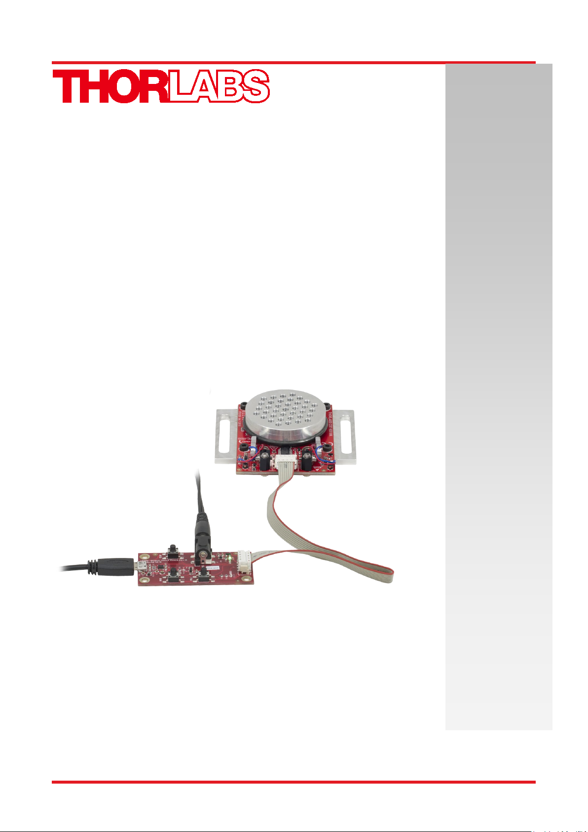
ELL18 and ELL18K
Rotation Stage Kit
Operating Manual
Original Instructions

Table of Contents
Chapter 1 Introduction .................................................................................................................. 1
Chapter 2 Safety............................................................................................................................. 2
2.1. General Warnings and Cautions ............................................................................. 2
Chapter 3 Description ................................................................................................................... 3
3.1. Environmental Conditions ...................................................................................... 3
3.2. Mounting .................................................................................................................. 4
Chapter 4 Operation ...................................................................................................................... 6
4.1. Getting Started ......................................................................................................... 6
4.1.1. Homing ............................................................................................................................ 6
4.1.2. Position Error Compensation .......................................................................................... 6
4.2. Controlling the Stage .............................................................................................. 7
4.2.1. Hand-held Controller ....................................................................................................... 8
4.2.2. Software Control ............................................................................................................. 9
4.2.3. Communications Protocol ............................................................................................. 10
4.2.4. Connecting Multiple Devices ......................................................................................... 10
4.2.5. Controlling the Stage without the handset .................................................................... 10
4.3. Frequency Search .................................................................................................. 12
4.4. Periodic Cycling of Devices Over Full Range of Travel ...................................... 12
4.5. Restoring Factory Settings ................................................................................... 12
4.6. Simultaneous Movement of Devices .................................................................... 12
Chapter 5 Troubleshooting and FAQ ........................................................................................ 13
5.1. Frequently Asked Questions ................................................................
5.2. Notes on Making a Picoflex Cable for Use when Daisy Chaining Devices ........ 15
Chapter 6 Specifications ............................................................................................................. 17
Chapter 7 Regulatory .................................................................................................................. 18
7.1. Declarations of Conformity ................................................................................... 18
7.1.1. For Customers in Europe .............................................................................................. 18
7.1.2. For Customers In The USA ........................................................................................... 19
Chapter 8 Thorlabs Worldwide Contacts .................................................................................. 20
................ 13

ELL18K Rotation Stage Evaluation Kit Chapter 1: Introduction
Chapter 1 Introduction
The ELL18 Rotation Stage is part of the Thorlabs series of resonant piezo motor circuits and bare modules for
OEM applications. The resonant piezo design of these motors offers fast response times and precise
positioning, and are therefore particularly useful in scanning applications.
The high-speed digital signal processing (DSP) architecture supports a multi-drop serial communication
protocol, and a set of digital IO lines allows the user to control the movement and state manually by switching
the lines high (5V) or low (0V).
The stage is designed for closed loop applications requiring rotational positioning with 43.0 µrad of resolution.
The stage delivers a travel range of 360° continuous rotation, however the displayed position and requested
position commands are in the range 0 to 359.99°.
Homing is achieved using a combination of a reflecting optical sensor (IR) for coarse (0.5 to 1.0 mm) positioning,
then a magnetic sensor for fine (1.0 µm resolution) positioning. Using the ELLO software, the user can modify
the offset value to shift the homing position (up to a ¼ of turn). Furthermore, coarse homing can be selected in
a clockwise (CW) or counter clockwise (CCW) direction (fine homing is always performed in a CCW direction
to guarantee repeatability).
The module is powered via an external 5V power supply supplied in the kit.
A hand-held controller is supplied with the ELL18K/M evaluation kit to allow homing and manual jogging and/or
positioning. The unit can also be driven remotely via PC-based software, downloaded from www.thorlabs.com.
A compatible USB driver and source code are included in the software download package.
Rev A April 2019 Page 1

ELL18K Rotation Stage Evaluation Kit Chapter 2: Safety
Chapter 2 Safety
For the continuing safety of the operators of this equipment, and the protection of the equipment itself, the
operator should take note of the Warnings, Cautions and Notes throughout this handbook and, where visible,
on the product itself.
Warning: Risk of Electrical Shock
Given when there is a risk of electrical shock.
Warning
Given when there is a risk of injury to the user.
Caution
Given when there is a possibility of damage to the product.
Note
Clarification of an instruction or additional information.
2.1. General Warnings and Cautions
Warning
If this equipment is used in a manner not specified by the manufacturer, the protection provided by the equipment
may be impaired. In particular, excessive moisture may impair operation.
The equipment is susceptible to damage from electrostatic discharge. When handling the device, anti-static
precautions must be taken and suitable discharge appliances must be worn.
Spillage of fluid, such as sample solutions, should be avoided. If spillage does occur, clean up immediately using
absorbent tissue. Do not allow spilled fluid to enter the internal mechanism.
If the device is operated over a prolonged time period, the motor housing may become hot. This does not affect
motor operation but may cause discomfort if contacted by exposed skin.
Do not bend the PCB. A bending load in excess of 500 g applied to the board may cause the PCB to deform,
which will degrade the performance of the controller.
Do not expose the stage to magnetic fields as this could affect the positioning and homing sensor operation. An
external magnetic field close to the sensor should be below +/- 5mT.
Page 2 DTN000524-D02

ELL18K Rotation Stage Evaluation Kit Chapter 3: Description
Chapter 3 Description
3.1. Environmental Conditions
Warning
Operation outside the following environmental limits may adversely affect operator safety.
Location Indoor use only
Maximum altitude 2000 m
Temperature range 15°C to 40°C
Maximum Humidity Less than 80% RH (non-condensing) at 31°C
To ensure reliable operation the unit should not be exposed to corrosive agents or excessive moisture, heat or
dust.
Do not expose the stage to magnetic fields as this could affect the positioning and homing sensor operation.
If the unit has been stored at a low temperature or in an environment of high humidity, it must be allowed to
reach ambient conditions before being powered up.
The unit is not designed to be used in explosive environments.
The unit is not designed for continuous operation. Lifetime will depend on several factors, e.g. load, number of
homing operations, number of frequency searches etc. The minimum lifetime is 100 km. See Chapter 4 for more
details.
Rev A April 2019 Page 3

ELL18K Rotation Stage Evaluation Kit Chapter 3: Description
on performing the
3.2. Mounting
Warning
The safety of any system incorporating this equipment is the responsibility of the pers
installation.
Caution
Although the module can tolerate up to 8kV of air discharge, it must be treated as ESD sensitive device. When
handling the device, anti-static precautions must be taken and suitable discharge appliances must be worn.
Do not expose the stage to magnetic fields as this could affect the positioning and homing sensor operation. An
external magnetic field close to the sensor should be below +/- 5mT.
When handling the stage, take care not to touch the wires to the motors.
Do not bend the wires over the motor spring as this affects the performance of the unit.
Do not allow the wires to contact other moving parts.
The recommended mounting orientation is horizontal. Two mounting brackets are shipped with the ELL18K/M
kit to allow mounting to a standard 1” or 25 mm pitch optical table or breadboard.
Figure 1 ELL18 rotation stage
Page 4 DTN000524-D02

ELL18K Rotation Stage Evaluation Kit Chapter 3: Description
The image below shows a diffraction grating mounted on the stage, with the diffracted light being incident on
the slit located to the right.
Figure 2 ELL18 with components fitted
Figure 3 Fixing the ELL18K to the work surface
1. Using the M3 x 6 mm (6-32 x ¼”) bolts supplied, fix the mounting brackets to the circuit board as
shown above.
2. Attach the mounting brackets to the work surface using appropriate standard fixings (not supplied).
Rev A April 2019 Page 5
ELL18K Rotation Stage Evaluation Kit Chapter 4: Operation
Chapter 4 Operation
4.1. Getting Started
Caution
Although the module can tolerate up to 8kV of air discharge, it must be treated as ESD sensitive device. When
handling the device, anti-static precautions must be taken and suitable anti-discharge appliances must be worn.
Do not expose the stage to magnetic fields as this could affect the positioning and homing sensor operation.
When power is applied, do not connect or disconnect the ribbon cable connecting the handset to the stage PCB.
Always remove power before making connections.
Warning
If the device is operated over a prolonged time period, the motor housing may become hot. This does not affect
motor operation but may cause discomfort if contacted by exposed skin.
1. Perform the mechanical installation as detailed in Section 3.2
2. Connect the handset to the stage if required.
Caution
The unit is easily damaged by connections with incorrect polarity. Pin 1 of the connector on the PCB is marked
with an arrow (see Figure 4 and Figure 5.) which should be adjacent to the red wire in the connecting cable.
3. Connect the stage to a 5V supply and switch ‘ON’. (A 5V PSU is supplied with the ELL18K/M).
4. Connect the unit to your PC if required, and wait for the drivers to be installed.
5. Home the stage. Homing is necessary to align the sensor and establish a datum from which all future
moves are measured.
4.1.1. Homing
Homing is achieved using a combination of a reflecting optical sensor (IR) for coarse (0.5 to 1.0 mm) positioning,
then a magnetic sensor for fine (1.0 µm resolution) positioning (the magnetic sensor is also used for positioning
during subsequent moves). Using the ELLO software, the user can modify the offset value to shift the homing
position (up to a ¼ of turn). Furthermore, coarse homing can be selected in a clockwise or counter clockwise
direction (the switch between coarse to fine homing is always performed in the same direction to guarantee
repeatability).
4.1.2. Position Error Compensation
The stage has a positioning error compensation algorithm. When moving from one position to another, the stage
detects the error between the requested and actual positions and will calculate an error compensation value,
which is then applied to the next movement. The calculation is applied automatically and is continually updated,
but generally the optimum value is calculated within 2 to 6 motions.
Page 6 DTN000524-D02

ELL18K Rotation Stage Evaluation Kit Chapter 4: Operation
4.2. Controlling the Stage
The stage can be controlled in three ways; via the handset, by the Elliptec software running on a PC, or by
writing a custom application using the messages described in the communications protocol document. Homing
and Jogging functionality can also be accessed by applying voltages to the digital lines on Connector J1. The
modes of control are described in the following sections.
Caution
In all modes, the angular position is requested and displayed from 0 to 359.99°. If a stage is driven past the
359.99° rotation point, the display reverts back to zero and counts up to 359.99° again. Furthermore, the unit
will not respond to requests for a move to a position greater than 359.99° and an error message will be
generated.
Rev A April 2019 Page 7
ELL18K Rotation Stage Evaluation Kit Chapter 4: Operation
4.2.1. Hand-held Controller
Caution
On power up the stage will move while the unit checks the sensors and then searches for the home position.
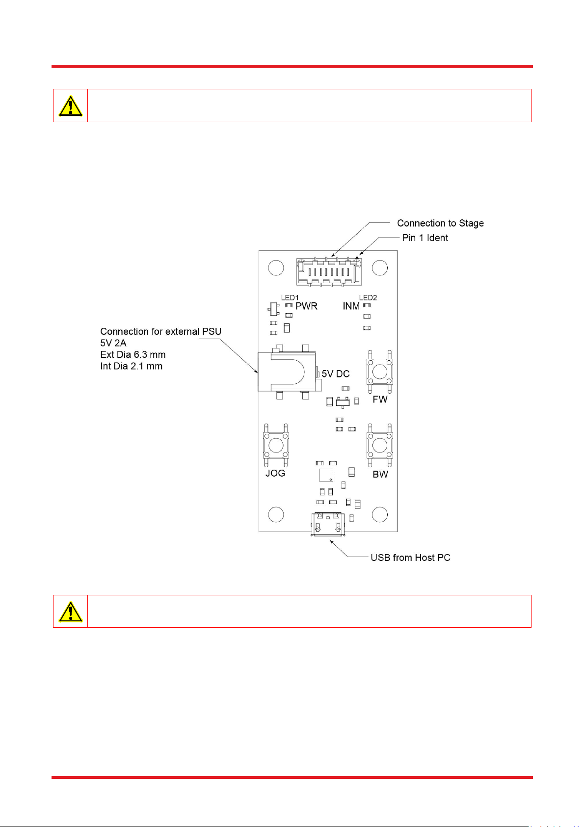
The hand-held controller supplied with the ELL18K Evaluation Kit features two buttons (marked FW and BW)
that allow control of the stage position. The handset also provides for connection to the host PC and to the
external 5V power supply. The external PSU connector allows the stage to be used in the absence of a PC,
with control being achieved via the handset buttons.
LED1 (green) is lit when power is applied to the unit. LED2 (red) is lit when the device being driven is in
motion.
Figure 4 Handset details
Caution
The stage must be homed before performing any Jog moves.
1. Home the stage by pressing the BW button.
2. To jog forward, press and hold JOG and then press FW. The default jog step value is 45 degrees.
The jog step size can be changed in the software GUI, see the helpfile for details.
3. To jog backward, press and hold JOG and then press BW.
Page 8 DTN000524-D02

ELL18K Rotation Stage Evaluation Kit Chapter 4: Operation
4.2.2. Software Control
When connected to the host PC, the stage can be controlled remotely, via the Elliptec software.
1. Download the Elliptic software from the downloads section at www.thorlabs.com. Double click the
saved .exe file and follow the on-screen instructions.
2. Connect the hand-held controller to the stage unit.
3. Connect the hand-held controller to the 5V Power Supply and switch on.
4. Connect the hand-held controller to the PC USB port and wait for the drivers to be installed.
5. Run the Elliptec software.
6. In the top left of the GUI panel displayed, select the COM port to which the device is connected, and
click ‘Connect’. The software will search the comms bus and enumerate the device.
7. Click the Home Offset ‘Get’ button, then click ‘Home’ to home the stage.
8. The GUI and device are now ready for use. See the helpfile supplied with the software for more
information.
Rev A April 2019 Page 9

ELL18K Rotation Stage Evaluation Kit Chapter 4: Operation
4.2.3. Communications Protocol
Custom move applications can be written in languages such as C# and C++.
The communication bus allows multi-drop communication with speeds at 9600 baud, 8 bit data length, 1 stop
bit, no parity.
Protocol data is sent in ASCII HEX format, while module addresses and commands are mnemonic character
(no package length is sent). Modules are addressable (default address is “0”) and addresses can be changed
and/or saved using a set of commands. Lower case commands are sent by user while upper case commands
are replies by the module.
Please refer to the communications protocol manual for more detail about commands and data packet formats.
4.2.4. Connecting Multiple Devices
When a device is first connected to the PC, it is assigned the default address '0'. The software can run
multiple devices; however, before more than one device can be recognised, each device must be assigned a
unique address. See below for a brief overview; detailed instructions are contained in the help file supplied
with the software.
Connect the first device to the PC USB port, then run the Elliptec software and load the device.
Change the address of the first device.
Connect the next device to the first device.
Change the address of the second device.
Multiple devices can be controlled individually, either via the Elliptec software or by a third party application
written using the messages detailed in the protocol document. Control via the handset is applied to all devices
simultaneously.
4.2.5. Controlling the Stage without the handset
Caution
During normal operation each motor is protected with a time out of 2.5 seconds to prevent overheating. Do not
override this protection or drive the motors continuously.
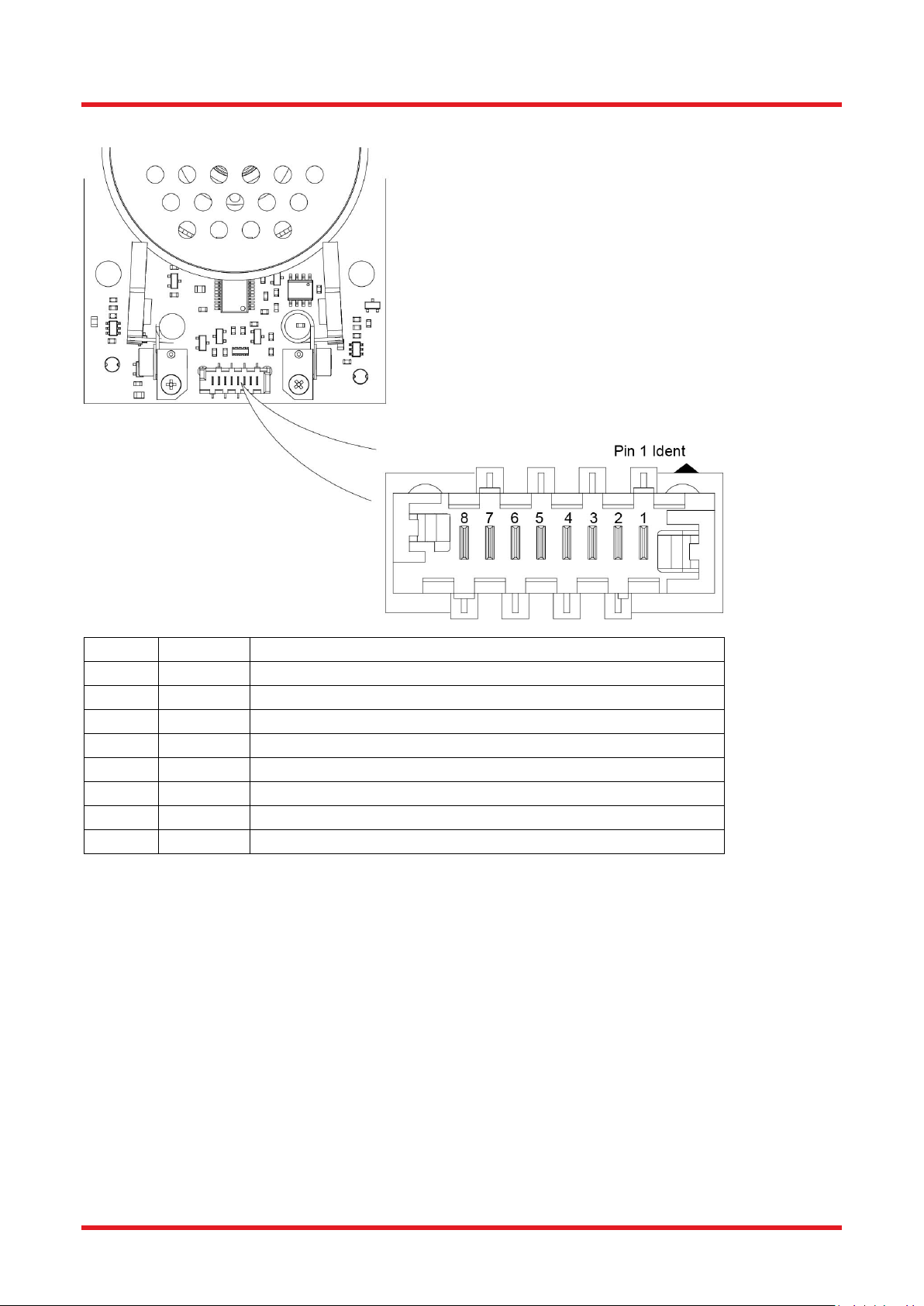
In the absence of the handset, the stage is controlled via digital lines: forward, backward and mode (J1 pins 7,
6 and 5) by shorting the corresponding line to ground (pin 1).
When the stage is moving, the open drain IN MOTION digital line (pin 4) is driven low (active low) to confirm
movement. The IN MOTION line goes high (inactive) when the move is completed or the maximum time-out
(2.5 seconds) is reached.
Warning
Do not exceed the voltage and current ratings stated in Figure 5.
Do not reverse polarity.
Page 10 DTN000524-D02
ELL18K Rotation Stage Evaluation Kit Chapter 4: Operation
PIN
TYPE
FUNCTION
1
PWR
Ground 2 OUT
ODTX - open drain transmit 3.3V TTL RS232
3
IN
RX receive - 3.3V TTL RS232
4
OUT
In Motion, open drain active low max 5mA
5
IN
JOG/Mode, active low max 5V
6
IN
BW Backward , active low max 5V
7
IN
FW Forward, active low max 5V
8
PWR
VCC +5V +/-10% 800mA
Connector J1 Pin Out
Connector model number MOLEX 90814-0808 Farnell order code 1518211
Mating connector model number MOLEX 90327-0308 Farnell order code 673160
Figure 5 Connector J1 pin out details
Rev A April 2019 Page 11

ELL18K Rotation Stage Evaluation Kit Chapter 4: Operation
4.3. Frequency Search
Due to load, build tolerances and other mechanical variances, the default resonating frequency of a particular
motor may not be that which delivers best performance. A frequency search can be performed using the Main
GUI Settings panel in the ELLO software, or by using the serial communication line
(SEARCHFREQ_MOTORX message), which offers a way to optimize the operating frequencies for backward
and forward movement.
This search can also be performed manually by restoring the factory settings as follows.
4.4. Periodic Cycling of Devices Over Full Range of Travel
Caution
Periodically, devices should be moved over the full range of travel, from one end to the other. This will help
minimize the build up of debris on the track and will prevent the motors digging a groove over the most used
area of contact. Typically, a travel cycle should be performed every 10K operations.
4.5. Restoring Factory Settings
Factory settings can be restored during the start up (calibration) test as follows:
1. Remove power from the rotator and disconnect the USB cable.
2. Press and hold the BW button (do not release until item 5).
3. POWER UP and reconnect the USB cable.
4. WAIT for red led to switch on.
5. Release BW. The unit will reboot and load the default factory values.
4.6. Simultaneous Movement of Devices
If more than one device is connected to the comms bus, movement of the devices can be synchronized. This
can be achieved either by using the handset, or by software. See the protocol document for details on how to
use the ‘ga’ message to synchronize moves. If using the handset, synchronized movement is hard wired, so if
multiple devices are connected, pressing the FWD or BWD buttons will move all devices.
Page 12 DTN000524-D02

ELL18K Rotation Stage Evaluation Kit Chapter 5: Troubleshooting and FAQ
The current drawn can overload the power supply. Allow 20 minutes of cool down between consecutive
Chapter 5 Troubleshooting and FAQ
5.1. Frequently Asked Questions
Stage is moving back and forth after power up
If the digital line “bw” is driven low before powering up the stage, the module will go into calibration mode.
Remove power to exit calibration mode. Keep line tight up to 3.3V or 5V rail during power up or use a serial
communication line instead.
Stage not moving
Check power supply lines ratings (polarity, voltage drop or range, available current) or reduce cable length.
Check module is not in boot loader mode (power cycle the module to exit boot loader) consumption must be
higher than 36mA at 5V.
Stage does not complete homing commands
Power cycle the unit.
Perform a frequency search on both motors.
Stage switching time increased / max load decreased
Check power supply voltage provided on J1 connector, increase voltage within specified limits if voltage drop
along cable goes below 5V during system operation.
Clean the moving surfaces. To avoid grease contamination, do not touch the moving parts.
Temperature change may affect the stage performance. Using the software to perform a frequency search will
compensate frequency as needed (required current could reach 1.2A during frequency search, use an addition
5V 1A power supply and a USB connection).
Integrators should search for optimal frequency on every power up sequence
(commands “s1”, “s2” see ELLx protocol document).
How do I restore the factory (default) settings
Factory settings can be restored during the start up (calibration) test – see Section 3.5.
Motor optimization does not work.
The optimization may fail if the device is damaged, if the load is heavily unbalanced or changed in position
during the optimization, or if the power supply is not stable.
Note
Do not run more than one device optimization at the same time on the same bus and power supply.
optimizations on the same device.
If the optimization fails, the device will try to reload the previous settings. If this reload fails, perform a frequency
search (see section 4.3) to reload the settings.
The unit is not responding after power up
During the power up sequence, if the user holds down the JOG, BW and FW lines to ground, the module will
go into a bootloader (firmware update) mode.
Power cycle the unit again without pressing the 3 buttons at the same time to exit from the bootloader mode.
Rev A April 2019 Page 13

ELL18K Rotation Stage Evaluation Kit Chapter 5: Troubleshooting and FAQ
The device is not responding during cleaning or optimization
This is normal.
The cleaning and the optimization routines block a device and the associated communication bus for several
minutes. When one of these routines is initiated, the bus is unavailable until the routine is completed, and the
device replies busy ‘0GS09’ to all commands except the stop command ‘0st’ (for a unit at address 0). The stop
request can take up to 5 seconds to abort the operation.
During these routines, the unit may increase in temperature by several degrees. Because of this inherent
temperature increase, consecutive cleaning and optimization routines should be avoided.
After optimization or cleaning, allow a 20 min cool down period before use.
What is the typical product life time?
ELL18 product life time is restricted by the wearing of moving surfaces and the motor contact as motion is
started (due to resonance build up) and performed (due to friction), and is expressed in km travelled. Lifetime
will depend on several factors (e.g. load, number of homing operations, number of frequency searches etc.)
and users must take into account all these factors when considering life time. For example, homing requires
more travel than a simple motion, and a frequency search may not generate any motion at all, but still energizes
the motors fully.
The unit is not designed for continuous operation. Users should aim for a duty cycle of less than 40% wherever
possible, and never exceed a duty cycle of 60% for longer than a few seconds. Furthermore, it is good practice
to move in the shortest path, so from position 350° to 5° it is better to move CW 15° (relative move) rather than
CCW 345° (absolute move).
A typical lifetime is more than 100 km or 600,600 revolutions.
Handling
The stage and interface board are robust to general handling. To ensure reliable operation, keep the surface of
the plastic track contacted by the motors free of oils, dirt, and dust. It is not necessary to wear gloves while
handling the linear stage, but avoid touching the track to keep it free of oils from fingerprints. If it is necessary
to clean the track, it may be wiped with isopropyl alcohol or mineral spirits (white spirit). Do not use acetone, as
this solvent will damage the plastic track.
Page 14 DTN000524-D02

ELL18K Rotation Stage Evaluation Kit Chapter 5: Troubleshooting and FAQ
5.2. Notes on Making a Picoflex Cable for Use when Daisy Chaining Devices
The multi-drop communications bus offers the option of connecting the stage to a hybrid network of up to 16
Elliptec resonant motor products and controlling the connected units with a device such as a microprocessor.
When multiple units are connected to the same interface board, all can be controlled simultaneously using either
the software or the buttons on the interface board.
When making a cable to operate multiple devices it is important to observe the correct pin orientation. The
following procedure offers guidance in making such a cable.
1. Gather together the parts required.
a) Ribbon cable 3M 3365/08-100 (Farnell 2064465xxxxx).
b) Female crimped connectors as required - model number MOLEX 90327-0308 (Farnell order code
673160) (Qty 1 female connector above is shipped with each stage unit).
c) Suitable screwdriver and scissors or other cutting tool.
2. Orientate the first connector correctly to mate with the connector on the stage, then arrange the ribbon
cable as shown with the red wire aligned with pin 1 (identified on the pcb by a small triangle). Slide the
connector onto the ribbon cable as shown.
Rev A April 2019 Page 15

ELL18K Rotation Stage Evaluation Kit Chapter 5: Troubleshooting and FAQ
3. Using a screwdriver or other suitable tool, push down the crimp of each pin to make connection with
the ribbon cable.
4. If other connectors are required they should be fitted at this point. Slide each connector onto the cable,
paying attention to the orientation as shown below, then crimp as detailed in step (3).
5. Fit the terminating connector which will mate with the interface board, taking care to align the cable
red wire with pin 1 as detailed in step (2).
Page 16 DTN000524-D02

ELL18K Rotation Stage Evaluation Kit Chapter 6: Specifications
General Specificationsa
Travel
360° Continuousb
Minimum Life Time
100 km (600,600 revolutions).
Max Speedc
430 °/s
Bidirectional Repeatabilityd
0.05 °
Homing Repeatability
0.25 °
Bidirectional Accuracye
0.4 °
Backlash
0.013 °
Encoder Resolution
143360 Counts/rev
Minimum Incremental Motion
0.002 °
Minimum Motor Holding Torque
(both motors engaged)
0.015 N•m
Axis Wobblef
0.019 °
Max Load
200 g (centered*)
Limit Switches
None
Mounting
4.2 mm (0.17") holes through PCB for attachment brackets
(supplied)
Rated Voltage
4.5 to 5.5 V
Typical Current Consumption During Movement
800 mA
Standby Current
0.05 A
Motor Type
Elliptec Resonant Piezo
8-Conductor Ribbon Cable Length (Supplied)
250 mm
8-Conductor Ribbon Cable Length (Maximum)
3 m
Operating Temperature Range
15 to 40 °C (59 to 104 °F)
Dimensions (with Brackets fitted)
81.0 x 86.4 x 21.5 mm (3.19” x 3.72” x 0.85”)
Weight (Stage plus Brackets)
90 g
Weight (Stage Only)
80 g
Chapter 6 Specifications
a
All values measured with a load of 64 g and a moment of inertia of 6600 g.mm2
b
duty cycle of 15 secs running, followed by a 20 sec cooling down period. If the running time is shorter, then
so is the required cool down time.
c
Some natural variability in the maximum speed may be experienced. Max speed will increase with usage.
d
Maximum difference between clockwise and anticlockwise movement to the same position
e
Maximum deviation from true
f
Max deviation from centre of rotation
Rev A April 2019 Page 17

ELL18K Rotation Stage Evaluation Kit Chapter 7: Regulatory
Chapter 7 Regulatory
7.1. Declarations of Conformity
7.1.1. For Customers in Europe
Page 18 DTN000524-D02

ELL18K Rotation Stage Evaluation Kit Chapter 7: Regulatory
7.1.2. For Customers In The USA
This equipment has been tested and found to comply with the limits for a Class A digital device, persuant to part
15 of the FCC rules. These limits are designed to provide reasonable protection against harmful interference
when the equipment is operated in a commercial environment. This equipment generates, uses and can radiate
radio frequency energy and, if not installed and used in accordance with the instruction manual, may cause
harmful interference to radio communications. Operation of this equipment in a residential area is likely to cause
harmful interference in which case the user will be required to correct the interference at his own expense.
Changes or modifications not expressly approved by the company could void the user’s authority to operate the
equipment.
Rev A April 2019 Page 19

ELL18K Rotation Stage Evaluation Kit Chapter 8: Thorlabs Worldwide Contacts
USA, Canada, and South America
Support: techsupport@thorlabs.com
UK and Ireland
Europe
Scandinavia
France
Email: sales.fr@thorlabs.com
Brazil
Email: brasil@thorlabs.com
Japan
China
Email: chinasales@thorlabs.com
Chapter 8 Thorlabs Worldwide Contacts
Thorlabs, Inc.
56 Sparta Avenue
Newton, NJ 07860
USA
Tel: 973-300-3000
Fax: 973-300-3600
www.thorlabs.com
www.thorlabs.us (West Coast)
Email: sales@thorlabs.com
Thorlabs GmbH
Hans-Böckler-Str. 6
85221 Dachau
Germany
Tel: +49-(0)8131-5956-0
Fax: +49-(0)8131-5956-99
www.thorlabs.de
Email: europe@thorlabs.com
Thorlabs SAS
109, rue des Côtes
78600 Maisons-Laffitte
France
Tel: +33 (0) 970 444 844
Fax: +33 (0) 825 744 800
www.thorlabs.com
Thorlabs Ltd.
1 Saint Thomas Place, Ely
Cambridgeshire CB7 4EX
Great Britain
Tel: +44 (0)1353-654440
Fax: +44 (0)1353-654444
www.thorlabs.de
email: sales@uk.thorlabs.com
Support: techsupport.uk@thorlabs.com
Thorlabs Sweden AB
Bergfotsgatan 7
431 35 Mölndal
Sweden
Tel: +46-31-733-30-00
Fax: +46-31-703-40-45
www.thorlabs.com
Email: scandinavia@thorlabs.com
Thorlabs Vendas de Fotônicos Ltda.
Rua Riachuelo, 171
São Carlos, SP 13560-110
Brazil
Tel: +55-16-3413 7062
Fax: +55-16-3413 7064
www.thorlabs.com
Thorlabs Japan, Inc.
3-6-3 Kitamachi,
Nerima-ku, Tokyo 179-0081
Japan
Tel: +81-3-6915-7701
Fax: +81-3-6915-7716
www.thorlabs.co.jp
Email: sales@thorlabs.jp
Thorlabs verifies our compliance with the WEEE (Waste Electrical and Electronic Equipment)
directive of the European Community and the corresponding national laws. Accordingly, all end
users in the EC may return “end of life” Annex I category electrical and electronic equipment
sold after August 13, 2005 to Thorlabs, without incurring disposal charges. Eligible units are
marked with the crossed out “wheelie bin” logo (see right), were sold to and are currently owned
by a company or institute within the EC, and are not dissembled or contaminated. Contact
Thorlabs for more information. Waste treatment is your own responsibility. “End of life” units
must be returned to Thorlabs or handed to a company specializing in waste recovery. Do not
dispose of the unit in a litter bin or at a public waste disposal site.
Thorlabs China
Room A101, No. 100
Lane 2891, South Qilianshan Road
Putuo District
Shanghai 200331
China
Tel: +86 (0) 21-60561122
Fax: +86 (0)21-32513480
www.thorlabschina.cn
Annex I
Page 20 DTN000524-D02

www.thorlabs.com
 Loading...