

THORLABS DCU223 SERIES, DCC1545M, DCC3240 SERIES, DCC3260 SERIES, DCC1645C Description And Sdk Manual
...
CCD and CMOS Cameras
DCU223x, DCU224x
DCC1240x
DCC1545M, DCC1645C
DCC3240X
DCC3260X
DCx Camera Functional
Description and SDK Manual
2016

Version:
Date:
4.80
8/11/2016
Copyright © 2016 Thorlabs Scientific Imaging

Contents
Foreword
1 General Information 10
101.1 Safety
121.2 Ordering Codes and Accessories
121.3 Requirements
131.4 DCx Camera Family
151.5 Contents
171.6 What's New in this Version?
2 Camera Basics 18
182.1 Operating Modes
182.1.1 Freerun Mode
202.1.2 Trigger Mode
212.1.3 Standby
222.2 Image Display Modes
252.3 Sensor
252.3.1 Sensor Sizes
9
262.3.2 Micro Lenses
292.3.3 Color Filter (Bayer filter)
312.3.4 Hot Pixels
332.3.5 Shutter Methods
372.3.6 Line Scan Mode
382.4 Reading Out Partial Images
382.4.1 Area of Interest (AOI)
422.4.2 Subsampling
432.4.3 Binning
442.5 Digitizing Images
442.5.1 Characteristics and LUT
472.5.2 Bit Depth and Digital Contrast Adjustment
502.6 Camera Parameters
502.6.1 Pixel Clock, Frame Rate, Exposure Time
512.6.2 Gain and Offset
512.6.3 Automatic Image Control
532.6.4 Applying New Parameters
532.7 Firmware and Camera Start
532.8 Digital Inputs / Outputs
542.8.1 Using Digital Inputs/Outputs
542.8.2 Flash Timing (Trigger Mode)
562.8.3 Flash Timing (Freerun Mode)
572.8.4 Serial Interface RS-232 (DC3240x only)

582.9 USB Interface
582.9.1 History and Development
582.9.2 Structure and Topology
592.9.3 USB 2.0 Cabling and Connectors
602.9.4 USB 3.0 Cabling and Connectors
602.9.5 Data Transmission and Bandwidth
3 Operation 62
623.1 uc480 Quick Start
643.2 Installation and Connection
643.2.1 System Requirements
653.2.2 DCx Driver Compatibility
653.2.3 Connecting a DCx Camera
673.3 Application Notes by Camera Model
673.3.1 DCC3260x Application Notes
683.3.2 DCC1240x / DCC3240x Application Notes
713.3.3 DCC1545M Application Notes
723.3.4 DCC1645C Application Notes
723.3.5 DCU223x Application Notes
723.3.6 DCU224x Application Notes
723.4 Installed uc480 Programs
733.4.1 uc480 Camera Manager
743.4.1.1 Camera List
743.4.1.2 Control Center
763.4.1.3 General Information
773.4.1.4 Camera Information
773.4.1.5 Creating a Support File
773.4.1.6 Additional Functions
813.4.1.7 Parameters
823.4.2 uc480 Hotpixel Editor
4 Programming (SDK) 85
864.1 First Steps to uc480 Programming
884.2 How to Proceed
884.2.1 Preparing Image Capture
884.2.1.1 Querying Information
894.2.1.2 Opening and Closing the Camera
894.2.1.3 Allocating Image Memory
914.2.1.4 Image Memory Sequences
924.2.2 Selecting the Display Mode
934.2.3 Capturing Images
934.2.3.1 Image Capture Modes
1014.2.3.2 Event / Message Handling

1054.2.4 Setting Camera Parameters
1054.2.4.1 Setting and Getting Parameters
1084.2.4.2 Automatic Image Control
1094.2.4.3 Image Pre-processing
1094.2.4.4 Get Camera Status
1094.2.4.5 Using the Camera EEPROM
1104.2.5 Saving Images and Videos
1104.2.5.1 Saving and Loading Single Frames
1104.2.5.2 Capturing AVIs
1134.2.6 Using Inputs and Outputs
1134.2.6.1 Input/Output Control
1164.3 Function Descriptions
1174.3.1 is_AddToSequence
1184.3.2 is_AllocImageMem
1204.3.3 is_AOI
1304.3.4 is_AutoParameter
1334.3.5 is_Blacklevel
1364.3.6 is_CameraStatus
1384.3.7 is_CaptureStatus
1414.3.8 is_CaptureVideo
1434.3.9 is_ClearSequence
1444.3.10 is_ColorTemperature
1484.3.11 is_Configuration
1554.3.12 is_Convert
1574.3.13 is_CopyImageMem
1584.3.14 is_CopyImageMemLines
1594.3.15 is_DeviceFeature
1614.3.15.1 Configuring the AOI Merge Mode
1654.3.15.2 Using the Log Mode
1684.3.15.3 Using Level Controlled Trigger
1694.3.15.4 Switching the Shutter Mode
1704.3.15.5 Using the Internal Image Memory
1724.3.15.6 Using the Line Scan Mode
1734.3.15.7 Configuring the Timestamp
1744.3.16 is_DeviceInfo
1774.3.17 is_DirectRenderer
1874.3.18 is_DisableEvent
1884.3.19 is_EdgeEnhancement
1914.3.20 is_EnableAutoExit
1924.3.21 is_EnableEvent
1954.3.22 is_EnableMessage
1974.3.23 is_ExitCamera

1984.3.24 is_ExitEvent
1994.3.25 is_ExitImageQueue
2004.3.26 is_Exposure
2024.3.26.1 Setting the Exposure Time
2054.3.26.2 Exposure Time with Fine Increments
2074.3.26.3 Setting the Long Exposure
2084.3.26.4 Setting the Dual Exposure
2104.3.27 is_ForceTrigger
2124.3.28 is_FreeImageMem
2144.3.29 is_FreezeVideo
2164.3.30 is_Gamma
2174.3.31 is_GetActiveImageMem
2194.3.32 is_GetActSeqBuf
2214.3.33 is_GetAutoInfo
2254.3.34 is_GetBusSpeed
2264.3.35 is_GetCameraInfo
2284.3.36 is_GetCameraList
2304.3.37 is_GetCameraLUT
2314.3.38 is_GetColorConverter
2324.3.39 is_GetColorDepth
2334.3.40 is_GetDLLVersion
2344.3.41 is_GetError
2354.3.42 is_GetFramesPerSecond
2364.3.43 is_GetFrameTimeRange
2384.3.44 is_GetImageHistogram
2414.3.45 is_GetImageInfo
2454.3.46 is_GetImageMem
2464.3.47 is_GetImageMemPitch
2484.3.48 is_GetNumberOfCameras
2494.3.49 is_GetOsVersion
2504.3.50 is_GetSensorInfo
2524.3.51 is_GetSensorScalerInfo
2534.3.52 is_GetSupportedTestImages
2554.3.53 is_GetTestImageValueRange
2564.3.54 is_GetTimeout
2574.3.55 is_GetUsedBandwidth
2584.3.56 is_GetVsyncCount
2594.3.57 is_HasVideoStarted
2604.3.58 is_HotPixel
2654.3.59 is_ImageFile
2694.3.60 is_ImageFormat
2764.3.61 is_InitCamera

2804.3.62 is_InitEvent
2824.3.63 is_InitImageQueue
2844.3.64 is_InquireImageMem
2864.3.65 is_IO
2994.3.66 is_IsVideoFinish
3014.3.67 is_LockSeqBuf
3024.3.68 is_LUT
3054.3.69 is_Measure
3094.3.70 is_ParameterSet
3124.3.71 is_PixelClock
3154.3.72 is_ReadEEPROM
3174.3.73 is_RenderBitmap
3194.3.74 is_ResetToDefault
3214.3.75 is_SetAllocatedImageMem
3244.3.76 is_SetAutoParameter
3324.3.77 is_SetBinning
3354.3.78 is_SetCameraID
3374.3.79 is_SetColorConverter
3394.3.80 is_SetColorCorrection
3414.3.81 is_SetColorMode
3454.3.82 is_SetDisplayMode
3494.3.83 is_SetDisplayPos
3504.3.84 is_SetErrorReport
3514.3.85 is_SetExternalTrigger
3534.3.86 is_SetFrameRate
3554.3.87 is_SetGainBoost
3564.3.88 is_SetGamma
3584.3.89 is_SetHardwareGain
3614.3.90 is_SetHWGainFactor
3634.3.91 is_SetImageMem
3644.3.92 is_SetOptimalCameraTiming
3664.3.93 is_SetRopEffect
3684.3.94 is_SetSaturation
3694.3.95 is_SetSensorScaler
3724.3.96 is_SetSensorTestImage
3744.3.97 is_SetSubSampling
3784.3.98 is_SetTimeout
3804.3.99 is_SetTriggerCounter
3814.3.100 is_SetTriggerDelay
3824.3.101 is_StopLiveVideo
3834.3.102 is_Trigger
3854.3.103 is_TriggerDebounce

3894.3.104 is_UnlockSeqBuf
3904.3.105 is_WaitEvent
3914.3.106 is_WaitForNextImage
3934.3.107 is_WriteEEPROM
3954.4 AVI Function Descriptions
3954.4.1 isavi_AddFrame
3964.4.2 isavi_CloseAVI
3964.4.3 isavi_DisableEvent
3974.4.4 isavi_EnableEvent
3984.4.5 isavi_ExitAVI
3994.4.6 isavi_ExitEvent
4004.4.7 isavi_GetAVIFileName
4014.4.8 isavi_GetAVIFileNameW
4024.4.9 isavi_GetAVISize
4034.4.10 isavi_GetnCompressedFrames
4044.4.11 isavi_GetnLostFrames
4054.4.12 isavi_InitAVI
4064.4.13 isavi_InitEvent
4074.4.14 isavi_OpenAVI
4084.4.15 isavi_OpenAVIW
4094.4.16 isavi_ResetFrameCounters
4104.4.17 isavi_SetFrameRate
4114.4.18 isavi_SetImageQuality
4124.4.19 isavi_SetImageSize
4144.4.20 isavi_StartAVI
4154.4.21 isavi_StopAVI
4164.5 RAW function descriptions
4164.5.1 israw_AddFrame
4164.5.2 israw_CloseFile
4174.5.3 israw_ExitFile
4174.5.4 israw_GetFrame
4184.5.5 israw_GetImageInfo
4194.5.6 israw_GetSize
4194.5.7 israw_InitFile
4204.5.8 israw_OpenFile
4214.5.9 israw_SeekFrame
4214.5.10 israw_SetImageInfo
4224.6 Obsolete functions
4254.7 Programming Notes
4254.7.1 Programming in C/C++
4264.7.2 Programming in C#
4274.7.3 Programming in VB.NET

4274.7.4 Programming in Delphi
4274.7.5 Programming with ActiveX
4274.7.6 Thread Programming
4294.8 Lists
4294.8.1 Complete List of All Return Values
4334.8.2 Error Codes of AVI Functions
4334.8.3 Linux: Not Supported Functions
5 Specifications 435
4365.1 Model Comparison
4385.2 Model Naming Conventions
4385.3 Camera and Sensor Data
4395.3.1 DCC3260x
4405.3.2 DCC1240x / DCC3240x
4445.3.3 DCC1545M
4465.3.4 DCC1645C
4485.3.5 DCU223x
4515.3.6 DCU224x
4545.4 Mechanical Specifications
4555.4.1 DCU223x, DCU224x
4565.4.2 DCC1240x
4575.4.3 DCC3240x
4585.4.4 DCC1545M, DCC1645C
4595.4.5 Flange Back Distance
4595.4.5.1 Calculating the Flange Back Distance
4615.4.5.2 Maximum Immersion Depth for Lenses
4625.4.6 Position Accuracy of the Sensor
4635.4.7 Filter Glasses
4635.4.7.1 Filter Types
4675.4.7.2 Mounting the Filter
4685.4.7.3 Cleaning the Filter Glasses
4705.4.8 Ambient Conditions
4715.5 Camera Interface
4715.5.1 DCU223x, DCU224x, DCC1240x
4715.5.1.1 I/O Connector - Pin Assignment
4735.5.1.2 Digital Input (Trigger) Circuit
4745.5.1.3 Digital Output (Flash) Circuit
4765.5.2 DCC3240x
4765.5.2.1 I/O Connector Pin Assignment
4775.5.2.2 GPIO Interface
4795.5.2.3 Digital Input (Trigger) Circuit
4805.5.2.4 Digital Output (Flash) Circuit
4815.5.2.5 RS-232 Serial Interface

4825.5.3 Camera EEPROM Specification
4835.6 Accessories for DCx cameras
4835.6.1 Accessories for DCU22xX / DCC1240X
4845.6.2 Accessories for DCC1x45X
4845.6.3 Accessories for DCC3240x / DCC3260x
6 Appendix 485
4856.1 Troubleshooting/FAQ
4866.1.1 PCs with Energy Saving CPU Technology
4876.2 Status LED on USB DCx Cameras
4896.3 Color and Memory Formats
4926.4 uc480 Parameter File (ini file)
4996.5 Definition of IP Protection Classes
4996.6 History of API functions
5016.7 Certifications and Compliances
5036.8 Thorlabs 'End of Life' Policy (WEEE)
5046.9 Exclusion of Liability and Copyright
5056.10Thorlabs Worldwide Contacts

Warning
Sections marked by this symbol explain dangers that might result in
personal injury or death. Always read the associated information
carefully, before performing the indicated procedure.
Attention
Paragraphs preceeded by this symbol explain hazards that could
damage the instrument and the connected equipment or may cause
loss of data.
© 2016 Thorlabs Scientific Imaging
9

DCx Camera Functional Description and SDK Manual
1 General Information
Thank you for purchasing a DCx camera!
You should first read the following chapters to get a quick overview on what is new in this software
version and on getting started with your new camera.
Getting started
DCx quick-start
First steps to DCx Camera programming
Further important information
What is new in this version?
Contents of this Manual
The DCx camera family
Specifications
Enjoy your new DCx camera!
1.1 Safety
Attention
All statements regarding safety of operation and technical data in this instruction manual
will only apply when the unit is operated correctly as it was designed for.
Prior to applying power to the DCx Camera Functional Description and SDK Manual,
make sure that the protective conductor of the 3 conductor mains power cord is correctly
connected to the protective earth ground contact of the socket outlet! Improper
grounding can cause electric shock with damages to your health or even death!
The DCx Camera Functional Description and SDK Manual must not be operated in
explosion endangered environments!
Do not remove covers! Do not obstruct the air ventilation slots in the housing!
Do not open the cabinet, there are no parts serviceable by the operator inside!
Refer servicing to qualified personnel!
Only with written consent from Thorlabs Scientific Imaging may changes to single
components be made or components not supplied by Thorlabs Scientific Imaging be
used.
This precision device is only serviceable if properly packed into the complete original
packaging. If necessary, ask for a replacement package prior to return.
Attention
The following statement applies to the products covered in this manual, unless otherwise
specified herein. The statement for other products will appear in the accompanying
documentation.
This equipment has been tested and found to comply with the limits for a Class A digital
device, pursuant to part 15 of the FCC Rules and meets all requirements of the Canadian
Interference-Causing Equipment Standard ICES-003 for digital apparatus. These limits are
© 2016 Thorlabs Scientific Imaging10

1 General Information
designed to provide reasonable protection against harmful interference when the
equipment is operated in a commercial environment. This equipment generates, uses,
and can radiate radio frequency energy and, if not installed and used in accordance with
the instruction manual, may cause harmful interference to radio communications.
Operation of this equipment in a residential area is likely to cause harmful interference in
which case the user will be required to correct the interference at his own expense.
Thorlabs Scientific Imaging is not responsible for any radio television interference caused
by modifications of this equipment or the substitution or attachment of connecting cables
and equipment other than those specified by Thorlabs Scientific Imaging. The correction
of interference caused by such unauthorized modification, substitution or attachment will
be the responsibility of the user.
The use of shielded I/O cables is required when connecting this equipment to any and all
optional peripheral or host devices. Failure to do so may violate FCC and ICES rules.
Attention
Mobile telephones, cellular phones or other radio transmitters are not to be used within
the range of three meters of this unit since the electromagnetic field intensity may then
exceed the maximum allowed disturbance values according to IEC 61326-1.
This product has been tested and found to comply with the limits according to IEC 613261 for using connection cables shorter than 3 meters (9.8 feet).
© 2016 Thorlabs Scientific Imaging
11

DCx Camera Functional Description and SDK Manual
DCU223M
CCD camera, monochrome, 1024x768 pixel, C mount
DCU223C
CCD camera, color, 1280x1024 pixel, C mount
DCU224M
CCD camera, monochrome, 1280x1024 pixel, C mount
DCU224C
CCD camera, color, 1280x1024 pixel, C mount
DCC1545M
CMOS camera, monochrome, 1280x1024 pixel, CS mount
DCC1645C
CMOS camera, color, 1280x1024 pixel, CS mount
DCC1240M
CMOS camera, monochrome, 1280x1024 pixel, C mount
DCC1240C
CMOS camera, color, 1280x1024 pixel, C mount
DCC3240M
CMOS camera, monochrome, 1280x1024 pixel, C mount, USB 3.0
DCC3240C
CMOS camera, color, 1280x1024 pixel, C mount, USB 3.0
DCC3240N
CMOS camera, NIR enhanced, 1280x1024 pixel, C mount, USB 3.0
DCC3260M
CMOS camera, monochrome, 1936x1216 pixel, C mount, USB 3.0
DCC3260C
CMOS camera, color, 1936x1216 pixel, C mount, USB 3.0
CAB-DCU-T1
Trigger cable for DCU22xX and DCC1240X cameras (Trigger In/Out)
CAB-DCU-T2
Trigger cable for DCU22xX and DCC1240X cameras (Trigger In only)
CAB-DCU-T3
I/O cable for DC3240 CMOS USB 3.0 cameras
Recommended
CPU speed
>2.0 GHz Intel Core i5 or Core i7
Memory (RAM)
8 GByte
For USB DCx cameras:
USB host controller
USB 3.0 Super Speed
Intel® motherboard chipset
Graphics card
Dedicated AGP/PCIe graphics card
Latest version of Microsoft DirectX Runtime 9.0c
Operating system
Windows 8.1 32 or 64 bit
Windows 7 32 or 64 bit
1.2 Ordering Codes and Accessories
Thorlabs C Mount Camera Lenses (objectives): See Thorlabs' website
1.3 Requirements
For operating the DCx cameras, the following system requirements must be met:
Drivers for network cards
To ensure optimum performance of the network connection, you need to install the latest drivers for your
network card. We recommend using the drivers of the following versions:
Intel® chipsets: version 8.8 or higher
Realtek chipsets: version 5.7 or higher
USB interface
Onboard USB 2.0 ports usually provide significantly better performance than PCI and PCMCIA USB
© 2016 Thorlabs Scientific Imaging12

1 General Information
Note on color cameras with high frame rates
For uc480 color cameras, the color conversion is done by software in the PC. When you use a color
camera with a high frame rate, the conversion might lead to a high CPU load. Depending on the PC
hardware used you might not be able to reach the camera's maximum frame rate.
adapters.
Current generation CPUs with energy saving technologies can cause bandwidth problems on the USB
bus. See section on PCs With Energy Saving CPU Technology.
Large multi-camera systems
Connecting a large number of cameras to a single PC may require a large working memory (RAM). This
is especially the case when many cameras with high sensor resolution are used.
If you want to set up such a system we recommend to use PCs with 64 bit operating systems and more
than 4 GB of RAM.
Direct3D graphics functions
The uc480 driver can use Direct3D to display the camera image with overlay information (Microsoft
DirectX Runtime had to be installed). On Windows systems, you can use the supplied "DXDiag"
diagnostic tool to check whether your graphics card supports Direct3D functions. To start the diagnostic
tool, click "Run…" on the Windows start menu (shortcut: Windows+R) and enter "DXDiag" in the input
box.
On the "Display" page of the diagnostic tool, click the button for testing the Direct3D functions.
OpenGL graphics functions
For OpenGL version 1.4 or higher must be installed. The OpenGL graphics functions do not work with QT
under Linux.
1.4 DCx Camera Family
DCx cameras stand for a range of compact and cost-effective cameras for professional use in
industrial, security and non-industrial applications. Equipped with the widely used USB 2.0 and
particularly USB 3.0 ports, they can easily be interfaced with a vast variety of systems. The images
are digitized in the camera and transmitted digitally to the PC. An additional frame grabber is not
required.
DCU cameras have state-of-the-art CCD sensors while the DCC models are CMOS based. The
CMOS models use either the global or the rolling shutter method; the CCD models use only the
global shutter method.
The DCx cameras are available as monochrome and color versions, DC3240 series has a NIR
version as well. The Model Comparison chapter shows the most important features of every series
at a glance.
USB 3.0 DCC3260x and DCC3240x CMOS Cameras
© 2016 Thorlabs Scientific Imaging
13

DCx Camera Functional Description and SDK Manual
Compact, fast and lightweight. The new DCC3260x and DCC3240x. The
29 x 29 x 29 mm small camera housing is not only ultra-compact, but due
to its magnesium casing and a total camera weight of 43 g, it is also ultralightweight and robust. The powerful camera offers a bandwidth of 400
MByte/s via USB 3.0. Power is supplied via the USB bus, hence an extra
power cable is obsolete.
With its lockable Micro USB connector the camera is perfectly suited even
for rough environments. Offering trigger and flash as well as two GPIOs
(General Purpose I/O), which can also be changed into a serial interface
(RS232). Hence, peripheral devices can easily be triggered or controlled.
But also the camera’s inner values are outstanding: brightness corrections
are easily realized by a comfortable 12 bit lookup table and hardware
gamma. 12 bit color depth offers a by factor 16 increased level of detail
compared to the usual 8 bit. Hardware based data preprocessing saves
additional CPU resources.
The DCC1240X and DCC22xX series feature a robust metal housing
with a standard mini-B USB 2.0 connector. Connection is additionally
possible via a lockable micro D-sub connector which also carries the optoisolated I/O signals.
The USB 2.0 interface is meanwhile available in every standard PC and
notebook/laptop and provides a gross bandwidth of 60 MByte/s. The
camera is connected and powered through the USB port by just a single
cable.
The DCC1x45X series features extremely compact cameras with high-speed
CMOS sensors. The LE models are designed for professional use in nonindustrial applications. Through the use of the widespread USB 2.0
technology, the cameras can easily be interfaced with a vast variety of
systems. These cameras are available with a plastic housing with CSmount lens adapter.
USB 2.0 DCC1240x (CMOS) and DCC22xX (CCD) Cameras
USB2.0 DCC1545M and DCC1645C Cameras
© 2016 Thorlabs Scientific Imaging14

1 General Information
1.5 Contents
The DCx Camera Manual contains all the information you need for operating your DCx camera. It
comprises the following parts:
Section A: Camera basics
In this section you will find a lot of important information on the technical background of your USB
camera. This section contains explanations on the DCx's operating modes, on sensor
technology, important camera parameters, and the USB interfaces. We recommend to read this
chapter to become familiar with the general functionality of the DCx Cameras.
Section B: Operation
Quick start to using your DCxCamera
Installing and Using DCx Camera software
These sections show how to connect cameras and start operation using the software tools .
Application notes by camera model
This section explains special features and limitations of some camera models.
Section C: Programming
First steps to programming with your DCxCamera
How to proceed
If you are not yet familiar with DCxCamera programming, we suggest that you first explore the
basic functional flows in this chapter. The function blocks contain almost all the functions available
for the uc480 API ordered by topics. The flowcharts help to easily find the appropriate API
function for a certain task.
Description of functions/Description of AVI functions
These chapters cover all the functions of the uc480 API in alphabetic order.
The AVI functions for video recording are implemented by the uc480_tools.dll which is also
included in the DCxCamera software package.
Obsolete functions
This chapter lists obsolote API functions and recommended alternatives.
Lists and programming notes
In this chapter, you will find useful information on how to use the DCxCamera programming API.
Programming environments, modes for DCxCamera color and image display as well as the
automatic image control functions are discussed here.
Section D: Specifications
Specifications
All information on the camera's sensor and performance, mechanical as well as electrical
specifications are contained in this section.
Accessories
Here you will find a list of accessories for DCx Cameras sorted by model.
Appendix
Information on Troubleshooting
Status LEDs on USB DCx cameras
Color and memory formats
uc480 parameter file (ini file)
© 2016 Thorlabs Scientific Imaging
15

DCx Camera Functional Description and SDK Manual
Definition of IP protection classes
© 2016 Thorlabs Scientific Imaging16

1 General Information
Cameras & functions
Described in chapter
New models in the USB 3 DCC camera family:
DCC3260
DCC3260
1.6 What's New in this Version?
Version 4.80 of the DCxCamera software package includes many new features and
enhancements. The following table gives you an overview of the major new functions.
New in Version 4.80.00
Older versions
See the History of uc480 Software Versions and History of uc480 API functions chapters.
© 2016 Thorlabs Scientific Imaging
17

DCx Camera Functional Description and SDK Manual
2 Camera Basics
This chapter explains the basics of DCx Camera technology.
Operating modes
Image display modes
Sensor
Reading out partial images
Digitizing images
Camera parameters
Firmware and camera start-up
Digital inputs/outputs
USB interface
2.1 Operating Modes
DCx Cameras support the following operating modes:
Freerun mode
Trigger mode
Standby
2.1.1 Freerun Mode
In freerun mode, the camera sensor captures one image after another at the set frame rate.
Exposure and readout/transfer of the image data are performed in parallel. This allows the
maximum camera frame rate to be achieved. The frame rate and the exposure time can be set
separately. The captured images can be transferred one by one or continuously to the PC. If trigger
mode is active, you need to disable it before activating freerun mode.
Note
Note on the schematic diagrams: These illustrations show a schematic view of the image capture
sequence. The sensor exposure and readout times and the transmission times depend on the
camera model and settings. The pre-processing time depends on the API functions you are using
(e.g. color conversion, edge enhancement).
For more information on flash timing see the Digital In-/Output (Trigger/Flash) chapter.
Continuous mode (live mode)
Images are captured and transferred continuously. You can use the DCxCamera flash outputs.
© 2016 Thorlabs Scientific Imaging18

2 Camera Basics
Freerun mode (live mode)
Freerun mode (snap mode)
* Flash function optional. See also Digital in-/output (trigger/flash).
Note
In freerun mode the flash function starts with the second image as the setting of the flash timing
depends on the finish of the first image. If you change the flash timing during operation, the freerun
mode will restart. Therefore the first image after the change is black.
Single frame mode (snap mode)
The next image exposed by the sensor will be transferred. In this mode, flash is not making sense
(only manually).
See also:
Basics: Shutter methods
Basics: Trigger mode
Basics: Applying new parameters
Programming:
Capture modes
© 2016 Thorlabs Scientific Imaging
19

DCx Camera Functional Description and SDK Manual
Software trigger mode with continuous image capture
2.1.2 Trigger Mode
In trigger mode, the sensor is on standby and starts exposing on receipt of a trigger signal. A
trigger event can be initiated by a software command (software trigger) or by an electrical signal
via the camera’s digital input (hardware trigger).
This chapter describes the different trigger modes you can use with the DCx Cameras. To choose
a mode, go to the Settings icon in the ThorCam application or use the API command.
Note
Note on the schematic diagrams: These illustrations show a schematic view of the image capture
sequence. The sensor exposure and readout times and the transmission times depend on the
camera model and settings. The pre-processing time depends on the API functions you are using
(e.g. color conversion, edge enhancement).
For more information on flash timing see the Digital In-/Output (Trigger/Flash) chapter.
Software trigger mode
When this mode is enabled, calling the "Snap" function triggers the capture of an image, which is
then transferred to the PC. If you call the "Live" function in this mode, the image capture is triggered
continuously and images are transferred continuously.
* Optional flash function. See also Digital input/output (trigger/flash)
Hardware trigger mode
When this mode is enabled, calling the is_FreezeVideo() (Snap) function makes the camera
ready for triggering just once. When the camera receives an electrical trigger signal, one image is
captured and transferred.
If you call the is_CaptureVideo() (Live) function, the camera is made ready for triggering
continuously. An image is captured and transferred each time an electrical trigger signal is
received; the camera is then ready for triggering again (recommended procedure).
Attention
When you use triggered image capture, the camera is only ready to process the next trigger signal
after completion of the data transfer to the PC. Trigger events that occur during image exposure or
data transfer are ignored. An internal counter records the number of ignored trigger events and can
be read out from the PC.
© 2016 Thorlabs Scientific Imaging20

2 Camera Basics
Hardware trigger mode with continuous image capture
)
rate max.frame
1
( time exposure Current tcapture
* Optional flash function. See also Digital input/output (trigger/flash)
Frame rate in trigger mode
With many sensors, the maximum frame rate is lower in trigger mode than in freerun mode
because these sensors expose and transfer sequentially. Which frame rate is possible in trigger
mode therefore depends on the exposure time. The time required for capturing a frame in trigger
mode can be approximated with the following formula:
Example: At the maximum exposure time, the frame rate is about half as high as in freerun mode;
at the minimum exposure time, the frame rate is about the same.
Freerun synchronization
This mode is currently not supported by DCx Cameras.
See also:
Basics: Freerun mode
Basics: Digital input/output (trigger/flash)
ThorCam: Settings > Trigger
Programming:
Image capture modes: Trigger
2.1.3 Standby
DCx Cameras can be set to a power-saving standby mode. Standby mode switches off the sensor
of CMOS cameras and the timing board of CCD cameras. The camera remains open in the
software.
In standby mode, the camera cools down and the number of hot pixels visible when longer
exposure times are used is reduced.
Standby is the default state when the camera is not open in the software. When you open the
camera or switch to a different mode (freerun or trigger mode), the camera wakes up from standby
mode.
Note
In standby mode, you can continue to use the camera's digital inputs or outputs.
© 2016 Thorlabs Scientific Imaging
21

DCx Camera Functional Description and SDK Manual
How the Bitmap mode works
2.2 Image Display Modes
The uc480 driver provides different modes for displaying the captured images on Windows
systems. We recommend using the Bitmap mode or the Direct3D functions, depending on your
specific application.
For a list of API functions for image display see How to proceed: Image display.
Attention
The "DirectDraw BackBuffer" and "DirectDraw Overlay Surface" display modes are obsolete.
Please use the Direct3D functions instead (see also Obsolete functions).
1. Bitmap mode (Device Independent Bitmap, DIB)
In Bitmap mode, images captured by the DCxCamera are written to the random access memory of
the PC. Programming the image display is up to the user. The application software uses the
is_RenderBitmap() function to initiate the image display by the graphics card. This may result in a
slightly higher CPU load as compared to the Direct3D display.
The advantage of Bitmap mode is that it is compatible with all graphics cards and that image data
in the memory is directly accessible. Programming of overlay functions is up to the user. Since the
operating system controls the image display, the image may be completely or partly overlapped by
other windows and dialog boxes.
2. Direct3D mode (only under Windows with DirectX)
In this mode, the uc480 driver writes the image data to the invisible area of the graphics card. This
process runs automatically and does not have to be controlled by the application software. It
requires an installed Direct3D driver, sufficient memory on the graphics card and Direct3D function
support by the graphics card (see System requirements). For this purpose, graphics cards
generally provide better performance than graphics chips integrated on the mainboard. In Direct3D
mode, the CPU load may be lower than in Bitmap mode. You can display overlay data and also
scale the video image.
The Direct3D mode and the overlay functions can be configured using the is_DirectRenderer()
API function.
© 2016 Thorlabs Scientific Imaging22

2 Camera Basics
How the Direct3D mode works
How the OpenGL mode works
Bitmap mode
Direct3D mode
OpenGL mode
Graphics card
requirements
Low. No special graphics
hardware required. Runs
on all systems.
High. Graphics card has
to support Direct3D.
Does not run on all
systems.
High. Graphics card has
to support OpenGL.
Operating system
Windows, Linux
Only Windows with
DirectX
Cross-platform
Programming
effort
Greater. Memory
management, event
handling and display
performed by the
application.
Low. Memory
management, event
handling and display
performed by DirectX.
High. OpenGL itself does
not provide functions for
opening windows or
reading files. However,
there are related
libraries, e.g. GLUT.
CPU load
Slightly increased by
copying of data.
Low. Display performed
by graphics card.
Low. Display performed
by graphics card.
Overlay functions
Not available. A simple
overlay can be
Integrated. Complex
overlays can be
Integrated.
OpenGL mode
OpenGL stands for Open Graphics Library and it is an interface specification for graphics
hardware. Unlike Direct3D OpenGL is not only available under Windows but also under Linux and
Mac OS, if OpenGL is supported by the graphics hardware. There are several implementations of
OpenGL, such as e.g. NVIDIA® or AMD/ATI. The implementations are always dependent on the
graphics card manufacturer.
Comparison of the display modes
The following table illustrates the major differences between the display modes:
© 2016 Thorlabs Scientific Imaging
23

DCx Camera Functional Description and SDK Manual
programmed by the user.
displayed without flicker.
Access to image
memory
Direct access possible.
Image data already
provided in user memory.
Possible using Steal
Mode. Single images
can be copied to the user
memory.
Direct access to
graphics card and image
memory.
© 2016 Thorlabs Scientific Imaging24

2 Camera Basics
Common sensor sizes (in inch)
2.3 Sensor
Sensor sizes
Micro lenses
Color filter (Bayer filter)
Hot pixels
Shutter methods
Line scan mode
2.3.1 Sensor Sizes
The size of a digital camera sensor is usually specified in inches. However, the specified value
does not indicate the actual size of the active sensor area. The sensor size specifications date
back to the formerly used tube systems: The curvature of the imaging surface of the camera tube
caused distortions to the display, reducing the usable capture area of a 1” tube to a rectangle with
a diagonal of 16 mm.
With the introduction of the semiconductor sensor technology, the dimensional specifications were
taken over from tube systems. For this reason, a sensor whose active area diagonal measures
16 mm is specified as a 1-inch sensor. The following illustrations show the most common sensor
sizes. The diameter in inch multiplied with 2/3 equals approximately the actual sensitiv area in
millimeters.
© 2016 Thorlabs Scientific Imaging
25

DCx Camera Functional Description and SDK Manual
Comparison of common sensor sizes and examples for
different fields of view
Using micro lenses to increase the effective fill factor
The size of each single sensor cell (pixel) depends on the size of the active sensor area and the
resolution. In general, less pixels over the same sensor area (or a larger sensor area with the same
resolution) will result in greater photo sensitivity of the sensor.
2.3.2 Micro Lenses
Micro lenses improve the fill factor
The fill factor is the percentage of the pixel area that is exposed to light during exposure. Ideally this
would be 100 %. Since other elements are located on the sensor surface besides the lightsensitive photodiodes, this value may be reduced to approx. 30–50 %, depending on the sensor
technology. The use of micro lenses compensates for this and increases the fill factor to 90 % or
more. Micro lenses collect the light that falls onto a photocell, thus increasing the useable sensor
area.
© 2016 Thorlabs Scientific Imaging26

2 Camera Basics
CMOS pixel design with Bayer filter (red) and micro lens
© 2016 Thorlabs Scientific Imaging
27

DCx Camera Functional Description and SDK Manual
Micro lenses without CRA correction
Image captured without CRA correction shows
shading
Micro lenses with CRA correction
Image captured with CRA correction
Micro lenses with CRA correction
Some sensors have micro lenses offset to the sensor edge. They compensate for shading created
by obliquely incident light. The angle of incident light is called Chief Ray Angle (CRA), the micro
lens offset is thus called CRA correction. The amount of micro lens shift is specified in degrees and
refers to the micro lenses in the corners of the sensor.
Note
Using parallel light on sensors with CRA correction may cause slight color variations. These may
occur, for example, if telecentric lenses are used. The following models are equipped with sensors
with offset micro lenses:
DCC1240x/DCC3240x
DCC1645C
© 2016 Thorlabs Scientific Imaging28

2 Camera Basics
Bayer RGB filter pattern
2.3.3 Color Filter (Bayer filter)
For technical reasons, digital image sensors can only detect brightness information, but no color
information. To produce color sensors, a color filter is applied to each photocell (pixel). The
arrangement of the color filters is illustrated in the following figure. Two out of every four pixels have
a green filter, one pixel has a red filter and one has a blue filter. This color distribution corresponds
to the color sensitivity of the human eye, and is called the Bayer filter pattern. With the help of the
Bayer pattern the correct brightness and color information can be calculated for each pixel. Full
sensor resolution is retained.
Bayer conversion
A Bayer conversion, also referred to as de-Bayering, is carried out to determine the color
information from the raw sensor data (raw Bayer). By default all DCx Cameras transmit the image
data to the PC in raw Bayer format. The PC then uses the functions of the uc480 API to convert the
image data to the color format you need for displaying or further processing the data.
To convert the colors, a filter mask moves over the image and calculates a color value for each
pixel from the surrounding pixels. The uc480 API provides two filter masks that differ in image
quality and CPU load.
Normal Quality (Mode IS_CONV_MODE_SOFTWARE_3x3/IS_CONV_MODE_HARDWARE_3x3)
A smaller filter mask is used for conversion. This algorithm has a low load on the CPU. The filter's
averaging function may cause a slight blur. Noise is reduced. This filter is recommended for
image processing tasks.
High Quality (Mode IS_CONV_MODE_SOFTWARE_5x5)
A large filter mask is used for conversion. This algorithm offers very accurate color positioning
and an increased level of detail. The CPU load is higher than with the normal filter. This filter is
recommended for visualization applications.
Note
Software conversion with high quality should only be used for sensors whose green pixels have the
same sensitivity. This applies to the following sensors:
DCU223C / DCU224C
DCC1240C, DCC3240C
For all other sensors, we recommend using the standard filter mask.
© 2016 Thorlabs Scientific Imaging
29

DCx Camera Functional Description and SDK Manual
Bayer conversion using the standard mask
See also:
Color conversion: is_SetColorConverter()
ThorCam: Settings > Camera > Pixel Data Format
© 2016 Thorlabs Scientific Imaging30

2 Camera Basics
Hot pixels detected in a monochrome camera
Hot pixels detected in a color camera
2.3.4 Hot Pixels
Definition
Hot pixels (or in a broader sense, defective pixels) are pixels that do not react linearly to incident
light – or do not react at all. They occur for various reasons, such as contamination during sensor
production or sensor age, and with both CCD and CMOS sensors. CCD sensors generally have
fewer hot pixels than CMOS sensors under the same operating conditions. With darkened sensors
and prolonged exposure times, hot pixels are visible as individual bright dots in the image. The
following factors promote the occurrence of hot pixels:
Long exposure times
High gain settings
High sensor operating temperature
Hot pixel correction
During the manufacture of our cameras, all sensors that will be used in DCx Cameras are checked
for hot pixels. In the process, images are taken with a darkened sensor and long exposure times.
Pixels with a brightness higher than a specific value are classified as hot pixels. A list of the
© 2016 Thorlabs Scientific Imaging
31

DCx Camera Functional Description and SDK Manual
DCx model
max. hot pixels stored
DCC1240x, DCC1545M, DCC1645C, DCC3240x (CMOS)
768
DCU223x, DCU224x (CCD)
20
coordinates of each hot pixel is stored in the camera EEPROM. The hotpixel correction is done in
the uc480 driver. However, some sensors also provide an internal hotpixel correction.
The maximum number of hot pixels stored in a DCx camera is:
How many hot pixels are on the camera's internal list depends above all on the defined threshold
values. It is not an indication of the quality of the sensors used.
When you enable the "Hotpixel correction" function in the DCx software, the software automatically
corrects the hot pixels in the captured image by calculating the average from the brightness value
of two neighboring pixels. When using color sensors, the hot pixel is corrected with the appropriate
color in raw Bayer format, i.e. before color conversion. The correction does not work with activated
subsampling and binning factors greater than 2x.
Note
The sensors are tested during manufacturing also for cold pixel and dead pixels. Sensors with
dead pixel clusters (more than two neighboring defective pixels of the same color) are rejected by
our quality control. When the camera is operated in very warm ambient conditions, other defective
pixels can occur, however.
Defining additional hot pixels
If additional hot pixels occur during use of the camera, you can add them to the camera's internal
hot pixel list. To do this, use the API function given below.
See also:
ThorCam: Hot pixel correction
uc480 Hotpixel Editor
Programming: is_HotPixel()
© 2016 Thorlabs Scientific Imaging32

2 Camera Basics
Global shutter sensor in live mode
2.3.5 Shutter Methods
Global shutter
Rolling shutter
Rolling shutter with global start
Note
Note on the schematic diagrams: These illustrations show a schematic view of the image capture
sequence. The sensor exposure and readout times and the transmission times depend on the
camera model and settings.
For more information on flash timing see the Digital In-/Output (Trigger/Flash) chapter.
General
The image is recorded in the sensor in four phases:
Reset pixels of the rows to be exposed
Exposure of pixel rows
Charge transfer to sensor
Data readout
The sensor cells must not be exposed during the readout process. The sensors of the DCx
Cameras have no mechanical shutters, but work with electronic shutter methods instead.
Depending on the sensor type, either the rolling shutter method or the global shutter method is
used.
Global shutter
On a global shutter sensor, all pixel rows are reset and then exposed simultaneously. At the end of
the exposure, all rows are simultaneously moved to a darkened area of the sensor. The pixels are
then read out row by row.
Exposing all pixels simultaneously has the advantage that fast-moving objects can be captured
without geometric distortions. Sensors that use the global shutter system are more complex in
design than rolling shutter sensors.
All CCD sensors as well as some CMOS sensors use the global shutter method.
© 2016 Thorlabs Scientific Imaging
33

DCx Camera Functional Description and SDK Manual
Global shutter sensor in trigger mode
Example for the rolling shutter effect with a moving car
* Optional flash function. The start time and duration are defined by the flash delay and duration
parameters (see also Camera settings: I/O).
Rolling shutter
With the rolling shutter method, the pixel rows are reset and exposed one row after another. At the
end of the exposure, the lines are read out sequentially. As this results in a time delay between the
exposure of the first and the last sensor rows, captured images of moving objects are distorted.
To counteract this effect, the DCx Camera software provides a global flash window where you set
the time by which flash activation is delayed. You can also specify the flash duration. This allows
implementing a global flash functionality which exposes all rows of a rolling shutter sensor
simultaneously.
Rolling shutter sensors offer a higher pixel density compared to global shutter CMOS sensors. The
rolling shutter system is used in DCC Cameras with high-resolution CMOS sensors.
Note
Some CMOS senors with global shutter can be operated also with rolling shutter. The operation in
the rolling shutter mode is used to reduce the image noise. This function is only supported from the
camera models DCC1240x/DCC3240x.
© 2016 Thorlabs Scientific Imaging34

2 Camera Basics
Rolling shutter sensor in live mode
Rolling shutter sensor in live mode with global flash window
Rolling shutter sensor in triggered mode with global flash window
* Optional flash function. The start time and duration are defined by the flash delay and duration
parameters (see also Camera settings: I/O).
Rolling shutter with global start
Some rolling shutter sensors also provide a global start mode, which starts exposure of all rows
simultaneously (see illustration). For best results, use a flash for this mode. No light is allowed to fall
on the sensor outside the flash period because otherwise the image brightness will be distributed
unevenly.
© 2016 Thorlabs Scientific Imaging
35

DCx Camera Functional Description and SDK Manual
Rolling shutter sensor in trigger mode with global start function
* Optional flash function. The start time and duration are defined by the flash delay and duration
parameters (see also Camera settings: I/O).
© 2016 Thorlabs Scientific Imaging36

2 Camera Basics
2.3.6 Line Scan Mode
Area scan sensor (matrix)
The sensors of area scan cameras have a matrix of many (usually between several hundred and
several thousand) rows and columns of pixels. State-of-the-art area scan sensors use only square
pixels with a consistent pixel pitch.
Area scan cameras are suitable for applications in which stationary or moving objects should be
captured as completely as possible in one image capture.
Line scan mode
In some applications, however, it is necessary to read out and transfer only one sensor line instead
of the entire sensor area. This applies, for example, to endless web inspection systems. These
systems often use line scan cameras for this reason. Their sensors have only one pixel row, which
they can read out at very high speeds in the kilohertz (kHz) range. Some DCxCamera models have
area scan sensors that optionally also offer a line scan mode. This mode can read out any pixel
row of the sensor at high speed.
There are two line scan modes to distinguish:
Fast line scan
In this mode, the sensor achieves very high line scan rates. Several hundred to thousand lines are
combined and transferred in one frame. The camera can be triggered on the beginning of a
frame, but not on each individual line. You can choose any line of the area scan sensor for the line
scan mode. Color images are not supported in this mode because Bayer color sensors need at
least two neighboring lines for color calculation.
Triggered line scan
In this mode, the sensor achieves lower line scan rates than in fast line scan mode. The camera
can be triggered on each individual line. Several hundred to thousand lines are combined and
transferred in one frame.
Color images are possible in this mode because Bayer color sensors can use two lines.
Note
The line scan mode is currently only supported by the monochrome DCC1240M and
DCC3240M,N models in form of the fast line scan mode. The triggered line scan mode is not
supported by any camera model yet.
See also:
ThorCam: Settings > Shutter
Programming:
Function: is_DeviceFeature()
© 2016 Thorlabs Scientific Imaging
37

DCx Camera Functional Description and SDK Manual
AOI readout on monochrome sensors
AOI readout on color sensors
2.4 Reading Out Partial Images
The camera sensors have defined resolutions which are given as the number of pixels (width x
height). However, for some applications it may be necessary to read out only a selected part of the
sensor area or to reduce the local resolution. For this purpose, the DCx Cameras provide various
functions:
Area of interest (AOI)
Subsampling (skipping) pixels
Binning (combining) pixels
These functions reduce the amount of data to be transferred and thus allow you to increase the
frame rate considerably, depending on the camera model.
2.4.1 Area of Interest (AOI)
Using this function, you can set the size and position of an area of interest (AOI) within an image. In
this case, only data included in this AOI will be read out and transferred to the computer. The
smaller partial image enables the camera to use a higher frame rate.
For information on the AOI position grid and the frame rates that your camera model can achieve
with AOI, see the model specifications in the Camera and sensor data chapter.
Note
Step widths for AOI definition (position grid): The available step widths for the position and
size of image AOIs depend on the sensor. The values defining the position and size of an AOI have
to be integer multiples of the allowed step widths.
For details on the AOI grids of the individual camera models, please see Camera and sensor data
© 2016 Thorlabs Scientific Imaging38

2 Camera Basics
and click a camera model.
Please note that, after defining an AOI, the resulting image may be darker if the camera cannot
maintain the originally set exposure time due to the increased frame rate.
© 2016 Thorlabs Scientific Imaging
39

DCx Camera Functional Description and SDK Manual
Multi AOI
The Multi AOI function allows defining more than one AOI in an image and transferring these AOIs
all at the same time. Only DCC1240x models support this feature. In the Multi AOI mode you can
define two or four AOIs in one image and transfer them simultaneously. The AOIs are positioned
side by side or one below the other, and share the same X or Y axis. This feature is not supported
in ThorCam at this time.
© 2016 Thorlabs Scientific Imaging40

2 Camera Basics
Sequence AOI mode
Apart from the multi AOI mode, DCC1240x and DCC3240x also support the sequence AOI
mode.This mode allows to define up to four AOIs, which need to have the same size but may differ
in position, exposure time or gain settings. This feature is not supported in ThorCam at this time.
See also:
ThorCam: Crop to Region of Interest
Programming: is_AOI()
© 2016 Thorlabs Scientific Imaging
41

DCx Camera Functional Description and SDK Manual
Subsampling on monochrome sensors
Subsampling on color sensors
2.4.2 Subsampling
Subsampling is a technique that skips multiple sensor pixels when reading out image data. This
reduces the amount of data to be transferred and enables higher camera frame rates. The
captured image has a lower resolution but still the same field of view compared to the full-resolution
image. This mode can be used as a fast preview mode for high-resolution cameras.
Color subsampling as performed by most color sensors skips pixels while maintaining colors (see
illustration). For some monochrome sensors, the camera also performs color subsampling,
resulting in slight artifacts.
Monochrome sensors and some color sensors ignore the Bayer pattern and the color information
gets lost (mono subsampling).
Depending on the model, DCx Cameras support different subsampling factors. Subsampling of
horizontal and vertical pixels can be enabled independently.
The Camera and sensor datas chapter lists the subsampling methods and factors supported by
each camera model.
© 2016 Thorlabs Scientific Imaging42

2 Camera Basics
Binning on monochrome sensors
Binning on color sensors
2.4.3 Binning
Binning is a function that averages or adds multiple sensor pixels to obtain a single value. This
reduces the amount of data to be transferred and enables higher camera frame rates. The
captured image has a lower resolution but still the same field of view compared to the full-resolution
image. This mode can be used as a fast preview mode for high-resolution cameras.
Color binning, as performed by most color sensors, combines only pixels of the same color (see
also the Color filter (Bayer filter) chapter). For some monochrome sensors, the camera also
performs color binning, resulting in slight artifacts.
Most monochrome sensors and some color sensors combine neighboring Bayer pattern pixels; in
this case, the color information gets lost (mono binning).
With CCD sensors, binning makes the images brighter because the pixel values are added up.
With CMOS sensors, pixel values are usually averaged; this reduces image noise.
Depending on the model, DCx Cameras support different binning factors. Binning of horizontal and
vertical pixels can be enabled independently.
The Camera and sensor data chapter lists the binning methods and factors the individual camera
models support.
© 2016 Thorlabs Scientific Imaging
43

DCx Camera Functional Description and SDK Manual
Imaging with linear characteristic
1
xy
Imaging with gamma characteristic
2.5 Digitizing Images
Characteristics and LUT
Bit depth and digital contrast adjustment
2.5.1 Characteristics and LUT
When perceiving or imaging a scene, the form of the imaging characteristic is crucial for displaying
the differences in brightness. With image processing (e.g. applications such as edge detection
and character recognition), linear characteristics are generally required. The human eye, on the
other hand, perceives differences in brightness based on a logarithmic characteristic, which often
approximates a gamma characteristic in practice. All three forms will be shown in the following.
Linear characteristic
If a system (e.g. a camera with a conventional CCD sensor) yields double the output value for
double the brightness, the system features a linear characteristic:
Gamma characteristic
Gamma characteristics (or gamma curves) are named after the Greek formula symbol γ. Gamma
curves are power functions of the form
and are often used in photography or image display on computer screens. A gamma value of 1
generates a linear characteristic again. A curve with the value γ = 2.2 used for computer screens is
shown in the figure below.
© 2016 Thorlabs Scientific Imaging44

2 Camera Basics
Image with linear characteristic
Image with gamma characteristic
)(lg xy
Imaging with logarithmic characteristic
Such a gamma characteristic brightens dark areas of an image, which corresponds more to the
perception of the human eye. In light areas of an image, the differences in brightness are
condensed for this.
Logarithmic characteristic
The effect of the logarithmic characteristic is even stronger. Here, the characteristic follows the
function
The following diagram illustrates how very large jumps in brightness in light areas of a scene only
cause small changes in image brightness. This explains why image sensors with a logarithmic
characteristic, in particular, are ideal for imaging scenes with very high dynamic range.
Lookup table (LUT)
With a lookup table (LUT) it is easy to apply characteristic curves to digital images. A LUT is a
table which assigns an output value to every possible input value. The figure below shows a LUT
which would binarize an image: For an 8 bit image, for example, this LUT would replace all pixels
with gray values 0...127 with value 0 and all pixels with gray values 128...255 with value 255.
Using LUTs has the advantage that calculations can be done very fast. Typical applications of
LUTs are enhancing image contrast, or gamma characteristics.
© 2016 Thorlabs Scientific Imaging
45

DCx Camera Functional Description and SDK Manual
LUT characteristic for binarizing an image
© 2016 Thorlabs Scientific Imaging46

2 Camera Basics
Various bit depths using a gray-scale gradient as an example
Bit depth
Brightness levels
8
28 = 256
10
210 = 1024
12
212 = 4096
14
214 = 16.384
Platform
USB 2.0
USB 3.0
CMOS sensors
8 bit
10 bit
CCD sensors
8 bit
-
2.5.2 Bit Depth and Digital Contrast Adjustment
Digitizing
Image sensor pixels first generate an analog voltage signal proportional to the amount of light that
strikes them. The image is digitized for further processing, i.e. the stepless signal is converted to a
digital numerical value. The following figure shows this using a gray gradient as an example
If the stepless gradient is imaged in a digital range in 2 bits, for example, the result is 22 = 4 levels;
for 4 bits, it is 24 = 16 levels, and so on. The intermediate brightness values of the original gradient
are irreversibly lost after digitization.
With around 200 levels or more, the jumps in brightness can no longer be discerned with the eye,
which is why current monitors and digital cameras use 8 bits (256 levels) per color channel (fully
adequate for visualization).
Bit depth in image processing
If digital image data undergoes further image processing, a bit depth greater than 8 may be
necessary. The computer is able to differentiate between these very fine differences in brightness
(no longer discernable by the eye) and process them. This is why industrial cameras often use 12
bits.
Note
Greater bit depths require extremely low-noise image sensors, however. As soon as the
differences in brightness created by noise are greater than the digitization levels, no further data is
gained.
Bit depth by sensors
Note
Color formats with a bit depth of more than 8 bits per channel are only supported by USB 3
DCC3240x camera models. Using color formats with higher bit depth increases the bandwidth
used by a camera.
© 2016 Thorlabs Scientific Imaging
47

DCx Camera Functional Description and SDK Manual
Image capture and histogram with minimal contrast (le.) and with optimum contrast after a contrast
adjustment (ri.)
Histogram and contrast
The brightness distribution of digital images is represented in a histogram. If an image has
optimum contrast, the histogram includes practically all brightness values between 0 and the
highest value (255 in 8-bit images). If an image has low contrast, the histogram only includes a
small number of the values; the image appears dull:
For improved display on the screen or when printed, the histogram can be spread to optimally
utilize the possible brightness levels. For this purpose, the dark parts of the image are further
darkened via an LUT characteristic and the light parts of the image are brightened. Thus the human
eye can better differentiate between the different brightness levels; the image has more contrast.
It must be noted, however, that subsequent processing with a computer will not yield more data.
Therefore, subsequent contrast adjustment via software is not necessary for use in image
processing. The computer can differentiate between the differences in brightness without contrast
adjustment.
Advantage of greater bit depth with contrast adjustment
The bit depth in the output image is crucial for contrast adjustment. The following figures illustrate
this. In the first example the 8 bit output image contains fewer than 100 brightness levels, as there
are no dark or very bright parts. The image is low-contrast.
With a contrast adjustment, the values of the histogram are spread in such a way as to create a
contrast-rich image. The fewer than 100 brightness values are now distributed across levels 0 to
255; gaps arise in the histogram and are visible as jumps in brightness in the resulting image.
© 2016 Thorlabs Scientific Imaging48

2 Camera Basics
Contrast adjustment with 8 bit output data
Contrast adjustment with 10 bit output data
The second example shows the same output image with a 10 bit bit depth right at the time of
capture. This image also has low contrast, as it features only average brightness values. The
greater bit depth allows the brightness values of the image to be imaged over 500 different digital
levels, however. The entire histogram includes 1,024 values in the 10 bit image (in contrast to 256
values with 8 bits).
This means that a contrast adjustment can now be made for screen display without a reduction in
quality. The 500 values of the output image are distributed over the 256 values of the 8-bit target
image in such a way that optimum contrast is the result. The large number of output values means
that there are no gaps in the histogram.
Note
This type of contrast adjustment can already be done in the camera when an image is digitized in
10 bits and transferred in 8 bit. In this case, optimum utilization of the 8 bit data is also important for
image processing.
© 2016 Thorlabs Scientific Imaging
49

DCx Camera Functional Description and SDK Manual
2.6 Camera Parameters
Pixel clock, frame rate, exposure time
Gain and offset
Automatic image control
Applying new parameters
2.6.1 Pixel Clock, Frame Rate, Exposure Time
Pixel clock
The basic parameter for camera timing is the pixel clock. It determines the speed at which the
sensor cells can be read out.
Attention
We recommend not setting the pixel clock any higher than necessary to achieve the desired frame
rate.
An excessive pixel clock can cause delays or transmission errors. If the data is read from the
sensor at a higher speed (high pixel clock), you will also need a faster transmission over the data
connection. Thus, by controlling the pixel clock, you can also influence the bandwidth required for a
camera.
The pixel clock influences the connected load and consequently the temperature inside the camera.
Frame rate
The possible range of settings for the frame rate depends on the currently selected pixel clock. You
can select a lower frame rate without changing the pixel clock. To set a higher frame rate, however,
you need to increase the pixel clock.
Exposure time
The exposure time depends on the currently selected frame rate and is preset to its reciprocal
value. You can select a shorter exposure time without changing the frame rate. To set a longer
exposure time, however, you need to reduce the frame rate.
Note
The increments for setting the exposure time depend on the sensor's current timing settings (pixel
clock, frame rate). The exposure time values are rounded down to the nearest valid value, if
required. For this reason, the actual exposure time can deviate slightly from the exposure time you
have selected.
See also:
ThorCam: Settings > Camera
is_PixelClock()
is_SetFrameRate()
is_Exposure()
© 2016 Thorlabs Scientific Imaging50

2 Camera Basics
2.6.2 Gain and Offset
Gain
In digital imaging, a voltage proportional to the amount of incident light is output by the sensor. To
increase image brightness and contrast, this signal can be amplified by an analog gain and offset
before the digitizing process. The results of analog signal processing are usually better than the
results of digital post-processing.
Analog amplification of the read-out pixel values increases overall image brightness and contrast.
Depending on the sensor type, a global gain value for all pixels (master gain) or a separate gain
value for each color (RGB gain) can be set.
Note
Using Sensor Gain: A signal gain will also result in a noise gain. High gain settings are therefore
not recommended.
We suggest the following gain settings:
1. Enable the Gain boost function (is_SetGainBoost()).
2. If required, adjust the gain setting with the master gain control.
Note
Linearity of sensor gain: You can set the gain factor in increments from 0 to 100.
For CCD sensors the gain increases usually not linear but disproportionate.
For CMOS sensors the gain increases linear. Some sensors have only 32 or fewer levels, so not
each step is assigned to a level.
The maximum gain factor settings also vary from sensor to sensor (see Camera- and sensor data).
Offset
Every digital image sensor has light-insensitive cells next to the active image area. These dark
pixels are used to measure a reference voltage (black level) which is subtracted from the image
signal. This compensates thermally generated voltages on the sensor which would otherwise falsify
the signals.
Normally, the sensor adjusts the black level automatically. If the environment is very bright or if
exposure times are very long, it may be necessary to adjust the black level manually.
2.6.3 Automatic Image Control
The uc480 driver provides various options to automatically adjust the image capture parameters to
the lighting situation. These include:
Auto exposure shutter (AES)
Auto gain control (AGC)
Auto white balance (AWB)
Auto frame rate (AFR)
The auto functions are used to adjust the average brightness and color rendering of the camera
image to their setpoint values, while trying to keep the frame rate at the highest possible value.
All controls are configured using the is_SetAutoParameter() SDK function.
Auto exposure shutter (AES)
The control of the average brightness is preferably achieved by adjusting the exposure, i.e. you set
the highest possible exposure time before gain is controlled. The auto exposure feature always
© 2016 Thorlabs Scientific Imaging
51

DCx Camera Functional Description and SDK Manual
uses the current exposure range which results from the selected pixel clock frequency and the
frame rate. You can set separate control range limits for exposure and gain.
Auto gain control (AGC)
The auto gain feature controls the camera master gain in a range from 0-100 %. You can set
separate control range limits for exposure and gain.
Auto frame rate (AFR)
With the exposure control function enabled, you can still change the frame rate manually or
automatically to maintain a dynamic exposure control range. A lower frame rate allows for longer
exposure times, but then the live image display may exhibit jitter. The objective of the automatic
frame rate control is to set the frame rate to an optimum value. This way, in all situations, the
automatic exposure control can use the required control range at the highest possible frame rate.
Auto white balance (AWB)
Depending on the lighting source, light can have different color temperatures so that the images
may have a color cast. At low color temperatures (e.g. light from incandescent lamps), the white
content is offset towards a red hue. At high color temperatures (e.g. light from fluorescent lamps),
the white content is offset towards a blue hue.
The white balance control feature uses the RGB gain settings of the camera to correct the white
level. This is achieved by adjusting the gain controls within the 0-100 % range until the red or blue
channel matches the average brightness of the green channel. In order to manually influence the
color rendering, you can adjust the setpoint values for the red and blue channels relative to the
green channel by using an offset value (see also ThorCam > Histogram).
Automatically disabling the control function
You can disable the control functionality automatically once the target value has been reached
(approximately) and after 3 regulations no improvement has been reached (API parameters
IS_SET_AUTO_WB_ONCE and IS_SET_AUTO_BRIGHTNESS_ONCE). An event/a message notifies the
system of this (see also is_InitEvent()). Alternatively, you can keep the control feature enabled
so that it responds to deviations from the target value.
Control speed
You can set the auto function speeds in a 0–100 % range. This influences the control increments.
High speed (100 %) causes a little attenuation of a fast-responding control and vice versa. The
control functions for average brightness and for color rendering use separate speeds.
In trigger mode, every frame is evaluated for automatic control. The freerun mode skips a number
of frames by default because in that mode, changes to the image parameters only become
effective after one or more image captures (see also Applying new parameters). With the "Skip
Frames" parameter (API parameter IS_SET_AUTO_SKIPFRAMES), you can select how many frames
should be skipped in freerun mode (default: 4). This parameter strongly influences the control
speed. Choosing small values can destabilize the automatic control.
Note
For higher frame rates select for the "Skip frames" parameter a bigger value. This reduces the
number of automatic adjustments that must be done by the camera.
Hysteresis
The automatic control feature uses a hysteresis function for stabilization. Automatic control is
stopped when the actual value lies in a range between (setpoint - hysteresis value) and (setpoint +
hysteresis value). It is resumed when the actual value drops below (setpoint - hysteresis value) or
exceeds (setpoint + hysteresis value). If the hysteresis value is increased, the control function will
stop sooner. This can be useful in some situations.
© 2016 Thorlabs Scientific Imaging52

2 Camera Basics
See also:
is_SetAutoParameter()
2.6.4 Applying New Parameters
New capture parameters (such as exposure time or gain settings) can be transferred to the camera
via software at any time. Depending on the operating mode, these settings will not always be
immediately effective for next image, however.
Freerun mode
In freerun mode, the camera is internally busy with capturing the next image while new
parameters are transmitted to the camera. Depending on the exact time of transmission, new
parameters might only come into effect two or even three images later.
Trigger mode
In this mode, the camera reverts to idle state between two images. When you change the camera
parameters, the new settings will be applied immediately to the next image.
2.7 Firmware and Camera Start
Every DCx camera has its own firmware that handles internal processes in the camera. The
camera firmware varies from model to model.
USB DCx Cameras have a two-tier firmware that is uploaded to the camera each to you connect it
to a PC:
1. Common firmware (uc480 boot)
The general firmware identifies what camera model you have connected, and uploads the
corresponding firmware.
2. Model-specific firmware (e.g.: uc480 DC1240x series)
The model-specific firmware is named after the camera type and provides the functions of the
relevant model.
Note
When you connect a USB DCxCamera with a Windows PC or a new USB port for the first time, it
is detected as a new device. This is normal standard behavior of the operating system.
The USB DCx Cameras firmware is part of the driver. The automatic upload always loads the
firmware that matches the driver installed in the camera.
2.8 Digital Inputs / Outputs
All DCx cameras (see Model comparison), except DCC1545M and DCC1645C, come with optoisolated inputs/outputs that can be used for triggering the camera and for flash control. DC3240x
cameras have in addition general purpose I/Os (GPIO). Use of the GPIOs for flash control is
possible to a certain degree. External triggering via the GPIO is not supported.
See also:
Basics: Trigger mode
ThorCam: Settings > Input/output
Specification: Electrical specifications
© 2016 Thorlabs Scientific Imaging
53

DCx Camera Functional Description and SDK Manual
Programming:
is_IO()
2.8.1 Using Digital Inputs/Outputs
Digital input (trigger)
Models with optocoupler input can use the digital input for externally triggering the image capture,
or query the applied signal level.
In trigger mode, a digital signal is applied to the camera's input. You can determine whether the
camera will respond to the rising or falling edge of the digital signal. After an internal delay, the
sensor is exposed for the defined exposure time. The captured image is then transferred to the
PC.
On models with general purpose I/Os (GPIO), you can query a voltage level at these inputs (TTL
compatible).
Digital output (flash)
The digital outputs can be used in both freerun mode and trigger mode. You can synchronize the
output level to the exposure time or set it statically.
Models with optocoupler output allow control of a DC voltage applied to the output. This allows
controlling a flash, either directly or via a separate flash controller unit. Models with general purpose
I/Os (GPIO) can output a voltage at these outputs (TTL compatible).
Note
Please read the notes on I/O wiring for your camera model in the Electrical specifications chapter.
Note
The settings specified for the digital output will be reset when the camera is disconnected from the
PC or the PC is powered down.
2.8.2 Flash Timing (Trigger Mode)
When using the digital output for flash control, you can set the delay and the duration of the flash.
The flash timing can be adjusted manually or automatically by the camera driver.
Note
Sensor latency and delay times The sensor latency is due to a number of technical factors,
including sensor type, image geometry, pixels clock and, with CCD sensors, the exposure time.
The latency is constant for a specific combination of parameters.
Trigger delay, flash delay and flash duration are optional and can be set by software.
The following illustrations show a schematic view of the image capture sequence. The sensor
exposure and readout times and the transmission times depend on the camera model and the
current parameter settings.
Automatic flash
If flash delay = 0 and flash duration = 0, the flash signal is automatically synchronized to the
exposure time. The automatic flash feature has the advantage that the flash is synchronized
automatically if the settings for image geometry or camera timing are changed. The disadvantage
is that the flash signal is active slightly longer than the exposure time. The flash duration with
automatic flash is longer for rolling shutter sensors than for global shutter sensors.
© 2016 Thorlabs Scientific Imaging54

2 Camera Basics
Flash timing with global shutter sensor, automatic flash,
optional trigger delay
Flash timing with rolling shutter sensor, automatic flash,
optional trigger delay
Manual flash synchronization
If one of the flash delay or flash duration parameters is set to a value greater than 0, you can shift
the flash signal to any point in the exposure time or change its duration. In this case, the flash delay
will be calculated exactly from the start of the exposure time (after the sensor latency time). When
manually synchronizing the flash signal to the exposure time, you can use the is_IO() function to
query the data you need.
The advantage of manual flash synchronization is that the flash can be precisely controlled based
on the start of exposure. This applies to both rolling and global shutter sensors. You can thus
achieve a higher accuracy with the manual flash synchronization than with the automatic flash
feature.
The disadvantage is that the flash signal has to be resynchronized whenever any settings for image
geometry or camera timing change.
Note
With rolling shutter sensors, you can avoid the rolling shutter effect by selecting suitable delay and
duration settings (global flash function). Using is_IO(), you can query the appropriate values.
Note
The flash output is reset with the start of the next image capture. This also applies if you have set a
longer flash duration.
© 2016 Thorlabs Scientific Imaging
55

DCx Camera Functional Description and SDK Manual
Flash timing, user-defined flash duration
Flash timing, user-defined flash duration and delay,
optional trigger delay
Flash timing in freerun mode with rolling shutter sensor, automatic flash
2.8.3 Flash Timing (Freerun Mode)
Automatic flash
In freerun mode, the automatic flash feature works in the same way as in trigger mode. As a result,
the flash output is continuously or almost continuously active (see illustration below).
Manual flash synchronization
Note
It is recommended to synchronize the flash manually in freerun mode. This applies to both rolling
and global shutter sensors.
In freerun mode, the manual flash synchronization works in the same way as in trigger mode.
© 2016 Thorlabs Scientific Imaging56

2 Camera Basics
Flash timing in freerun mode with global shutter sensor, manual flash
2.8.4 Serial Interface RS-232 (DC3240x only)
DC3240x cameras are equipped with a serial interface (RS-232). It provides functionality for
communication with peripheral devices (e.g. lighting controller, lens controller or the serial port of a
PC). Before you can send data through the camera's serial interface, one or more virtual COM
ports have to be defined on the PC. Once defined, they can be used for data communication with
appropriate software just like any physical COM port.
To set up and use the serial interface, the "Additional functions" dialog box is provided in the uc480
Camera Manager. For the serial interface specifications, please refer to the DC3240x Serial
Interface Wiring (RS-232) chapters.
© 2016 Thorlabs Scientific Imaging
57

DCx Camera Functional Description and SDK Manual
2.9 USB Interface
History and development
Structure and topology
USB 2.0 cabling and connection
USB 3.0 cabling
Data transmission and bandwidth
2.9.1 History and Development
The Universal Serial Bus (USB) is an interface which enables you to easily connect various devices
to a PC. As all data exchange is controlled by the PC, no additional interface controller is needed.
Further advantages of USB are:
The PC does not have to be shut down when connecting USB devices (hot plugging).
USB devices can be supplied with power from the PC.
High bandwidth for data transmission.
The USB standard was developed by a group of companies including Compaq, IBM, Intel, and
Microsoft. Version 1.0 was presented in 1995. The slightly faster USB 1.1 standard followed in
1998.
At first, the USB interface was designed to connect peripheral devices such as printers, mice, or
keyboards. With the introduction of USB 2.0 in 2000, the transfer rate increased to 480 Mbit/s,
making USB 2.0 suitable for connecting devices with higher data volumes (such as mass storage
devices, scanners, or cameras).
In 2008, with USB 3.0 a new version of the interface has been published, which is significantly
faster than USB 2.0 (400 MByte/s).
2.9.2 Structure and Topology
USB uses a tree topology and is host-controlled. That means that a PC with host functionality is
mandatory for using USB. Therefore, it is not possible to directly connect two USB devices (with
the exception of USB on-the-go compliant devices). Neither is it possible to connect a camera to a
PDA device.
Theoretically, 127 devices can be connected to a host controller. Using external hubs or repeaters,
even more devices can be connected, and from a greater distance. Provided that a maximum of 5
hubs/repeaters may be daisy-chained, USB devices can be connected in up to seven levels.
© 2016 Thorlabs Scientific Imaging58

USB topology
Note
Basic design of a USB cable
2 Camera Basics
The maximum bandwidth of 480 Mbit/s per USB 2.0 host or 400 MByte/s per USB 3.0 host cannot
be exceeded. Therefore, the maximum possible frame rate will be reduced if image data from
multiple USB cameras is transferred simultaneously.
The available bandwidth might also be decreased when you use hubs or repeaters. You can
reduce the bandwidth required for each camera by lowering the frame rate or the image size.
2.9.3 USB 2.0 Cabling and Connectors
In order to comply with the specifications, the maximum length of USB 2.0 cables is limited to 5 m.
Longer cables may be connected if you use high-quality material. The USB bus provides power
supply with 5 V and 500 mA max. Many USB devices use the bus power and do not need external
power supply (bus-powered devices).
Cable design
The following illustration shows the basic design of a shielded USB cable:
D+/D-: data transfer
+5 V/GND: power supply
Connector types
On the PC side, USB 2.0 cables are equipped with a standard A type plug (four pins) and on the
device side either with a standard B plug (four pins) or a mini-B plug (five pins).
© 2016 Thorlabs Scientific Imaging
59

DCx Camera Functional Description and SDK Manual
Basic design of a USB 3.0 cable
USB 3.0 cable standard A
USB 3.0 cable standard B
USB 3.0 cable micro B
2.9.4 USB 3.0 Cabling and Connectors
In order to comply with the specifications, the maximum length of USB 3.0 cables is limited to 38 m. With the use of repeaters cable lengths up to 20 m are possible. With signal conversion into
optical signals cable lengths up to 100 m are possible. The USB bus provides power supply with
5 V and 900 mA max.
Cable design
The following illustration shows the basic design of a shielded USB cable:
SSTX+/-: SuperSpeed Transmit (data transfer from host to the device)
SSRX+/-: SuperSpeed Receive (data ransfer from device to the host)
D+/D-: data transfer (USB 2.0)
+5 V/GND: power supply
Connector types
On the PC side, USB 3.0 cables are equipped with a standard A type plug (8 pins) and on the
device side either with a standard B plug or a micro-B plug.
While a USB 3.0 standard A plug and a USB 2.0 port can be used together (with the restriction that
only USB 2.0 speed is possible), the standard B and micro B plug are no longer compatible with
USB 2.0 ports.
2.9.5 Data Transmission and Bandwidth
USB 2.0
The USB 2.0 standard specifies an overall bandwidth of 480 Mbit/s shared between different
transmission modes. DCx Cameras use the USB 2.0 bulk mode for transmitting images. This
mode uses error correction to ensure correct delivery of the image data, but does not guarantee a
© 2016 Thorlabs Scientific Imaging60

2 Camera Basics
fixed bandwidth. To ensure error-free communication with all connected devices at all times, the
maximum bandwidth for payload data is limited to 416 Mbit/s.
Theoretically, up to 50 MByte/s of data can be transmitted in this mode, but in practice, this value is
hardly ever reached. A high-performance desktop PC can transmit about 40 MByte/s, most
notebooks or embedded PC systems even less than that.
The overall bandwidth can be increased by the use of USB 2.0 expansion cards. These cards are
available for the PCI and PCIe buses and have their own host controller chip.
Note on hardware selection
To achieve optimum USB bandwidth, it is important to use a powerful mainboard chipset. The
mainboard chipsets from e.g. Intel® or NVIDIA® provide very good results.
Note on image content and bandwidth usage
For USB cameras, you can use a white test image to check the camera's maximum load on the
USB bus. Due to the transmission process, completely white camera images require a somewhat
more bandwidth on the USB bus than completely black images.
USB 3.0
Compared to USB 2.0, USB 3.0 offers a tenfold increased bandwidth of 5 Gbit/s, i.e. images can
be transmitted with a bandwidth of 400 Mbytes/s.
© 2016 Thorlabs Scientific Imaging
61

DCx Camera Functional Description and SDK Manual
Connect the camera
Install the latest version of the DCx software. Then connect the DCx camera with the PC.
USB cameras are automatically detected as new hardware under Windows. Check the
status LEDs on your camera to see if the camera has been correctly identified.
See also:
Installation and connection
Troubleshooting
Connection - Status LED
Configure the camera
USB DCx Cameras are ready for use right out of the box. You can assign a unique ID to
your camera with the uc480 Camera Manager.
See also:
uc480 Camera Manager
Assigning a camera ID in the camera manager
Firmware and camera start
Capture images
The uc480 software package includes many sample programs that you can use to try out
the extensive functionality of your DCx camera. We recommend starting off with the
ThorCam application. To run the application, simply double-click the corresponding icon
on your Windows desktop.
See also:
ThorCam Software User Manual (Separate Document)
Camera basics: Operating modes
Customize the key camera properties
Select the Settings icon on the menu bar to open the dialog box for modifying the
camera properties.
3 Operation
This chapter explains how to connect the DCx camera and how to use the applications contained in
the uc480 software package.
Quick start
Installation and connection
Installed uc480 programs
o ThorCam: A comprehensive viewer for exploring the camera functionality (See separate
ThorCam User's Manual)
o uc480 Camera Manager: The central tool for managing all connected DCx Cameras.
o uc480 Hotpixel Editor: A tool to edit the sensor hot pixel list stored in the camera.
3.1 uc480 Quick Start
This chapter show how to quickly get started with your DCx camera. You will learn how easy it is to
connect the camera and explore important functions. For further steps of integrating the DCx
camera into your own applications please also see the First steps to uc480 programming chapter.
© 2016 Thorlabs Scientific Imaging62

3 Operation
The "Camera" tab provides all the parameters for adjusting the camera's speed. You
can increase the pixel clock to run the camera at a higher frame rate. Reduce the pixel
clock if transmission errors occur too often.
On the "Image" tab, you find various sensor gain controllers. Use the "Master gain"
controller to increase image brightness if no longer exposure time setting is possible.
Switch to the "AES/AGC" tab to enable the Auto Exposure Shutter (AES) and Auto Gain
Control (AGC) features.
Tip: Select a low sensor gain to minimize visible noise.
If you are using a color camera, you should activate sensor color correction on the
"Color" tab in order to achieve rich vibrant colors for on-screen display. To adapt a color
camera to the ambient light conditions, it is essential to carry out Auto White Balance
(AWB). Aim the camera at a surface of a uniform gray color, then enable the "Image
white balance: Enable" and "Run once" check boxes on the "AWB" tab.
See also:
ThorCam Software User Manual (Separate Document)
Camera basics: Camera parameters
Activate trigger and flash modes
DCx Cameras provide the possibility to trigger the image capture and to have the flash
controlled by the camera. To switch the camera to trigger mode, go to the camera
properties as described above, select the "Trigger" tab and enable the desired mode.
To trigger on "falling edges" or "rising edges", a digital signal has to be applied to the
camera. When you are finished with the trigger settings, select "Start Continuous
Trigger" or "Triggered Snapshot" icons on the menu bar to start the triggered image
capture.
If you have connected the digital output on your DCx camera to a flash controller, you can
configure the flash function on "Input/Output" tab. Enable "Flash high active" and "Global
exposure window". This way, the DCx camera automatically activates the flash during
the exposure time.
See also:
ThorCam Software User Manual (Separate Document)
Camera basics: Digital input/output
Specifications: Electrical specifications
Save the camera settings and images
With ThorCam, saving single frames or videos is very easy to do. Just choose the
relevant option on the "File" menu. If you have recorded AVI videos, you can play them
through Windows Media Player, ImageJ, or other AVI-compliant viewer with MotionJPEG decoding capability.
See also:
ThorCam Software User Manual (Separate Document)
© 2016 Thorlabs Scientific Imaging
63

DCx Camera Functional Description and SDK Manual
Recommended
CPU speed
>2.0 GHz Intel Core i5 or Core i7
Memory (RAM)
8 GByte
For USB DCx cameras:
USB host controller
USB 3.0 Super Speed
Intel® motherboard chipset
Graphics card
Dedicated AGP/PCIe graphics card
Latest version of Microsoft DirectX Runtime 9.0c
Operating system
Windows 8.1 32 or 64 bit
Windows 7 32 or 64 bit
Note on color cameras with high frame rates
For uc480 color cameras, the color conversion is done by software in the PC. When you use a color
camera with a high frame rate, the conversion might lead to a high CPU load. Depending on the PC
hardware used you might not be able to reach the camera's maximum frame rate.
3.2 Installation and Connection
System requirements
Installing uc480 software under Linux
Connecting a USB DCx camera
3.2.1 System Requirements
For operating the DCx cameras, the following system requirements must be met:
Drivers for network cards
To ensure optimum performance of the network connection, you need to install the latest drivers for your
network card. We recommend using the drivers of the following versions:
Intel® chipsets: version 8.8 or higher
Realtek chipsets: version 5.7 or higher
USB interface
Onboard USB 2.0 ports usually provide significantly better performance than PCI and PCMCIA USB
adapters.
Current generation CPUs with energy saving technologies can cause bandwidth problems on the USB
bus. See section on PCs With Energy Saving CPU Technology.
Large multi-camera systems
Connecting a large number of cameras to a single PC may require a large working memory (RAM). This
is especially the case when many cameras with high sensor resolution are used.
If you want to set up such a system we recommend to use PCs with 64 bit operating systems and more
than 4 GB of RAM.
© 2016 Thorlabs Scientific Imaging64

3 Operation
Direct3D graphics functions
The uc480 driver can use Direct3D to display the camera image with overlay information (Microsoft
DirectX Runtime had to be installed). On Windows systems, you can use the supplied "DXDiag"
diagnostic tool to check whether your graphics card supports Direct3D functions. To start the diagnostic
tool, click "Run…" on the Windows start menu (shortcut: Windows+R) and enter "DXDiag" in the input
box.
On the "Display" page of the diagnostic tool, click the button for testing the Direct3D functions.
OpenGL graphics functions
For OpenGL version 1.4 or higher must be installed. The OpenGL graphics functions do not work with QT
under Linux.
3.2.2 DCx Driver Compatibility
Attention
Support of older DCC1545M cameras by driver versions 3.10 and higher
From driver version 3.10 onwards, only USB board revision 2.0 or higher are supported. To operate a camera with an
earlier USB board revision, you will need the uc480 driver version 2.40. Please contact Thorlabs
The LED on the back of the camera housing also indicates the USB board version (see DCx Status LED). In addition,
the uc480 Camera Manager version 3.10 or higher provides information about the compatibility (see Camera Manager).
An incompatible camera will be displayed as free and not available.
3.2.3 Connecting a DCx Camera
Please install the software first as described in the Quick Start Guide. Connect the DCx camera to
the PC, using the USB cable. The camera will be recognized automatically and the necessary
driver software is being installed:
When the camera has been correctly installed, the LED on the back of the camera lights up green.
Note
The first time you connect a USB DCx camera to a USB port under Windows, two driver files will
be registered. The first file (uc480 boot) contains the generic driver, the second file the modelspecific driver.
The model will be immediately recognized whenever you connect the camera to this port again. If
you use a different port, the registration will be repeated. Under Windows the camera will show up
in the uc480 Camera Manager's camera list.
© 2016 Thorlabs Scientific Imaging
65

DCx Camera Functional Description and SDK Manual
The DCx Cameras can be connected to a USB port either directly or via hubs and repeaters. A
wide range of different hubs and repeaters are available commercially. The USB 2.0 hubs being
used must be "full powered" hubs that are able to provide 500 mA per USB port. "Low Powered"
hubs, in comparison, only supply 100 mA per port, which is not sufficient for DCx Cameras.
Note
To use maximum bandwidth, we recommend connecting the cameras directly to the USB ports on
the mainboard. Many USB ports on PCI/PCIe cards and the USB ports on the front of the PC often
supply lower bandwidth.
Attention
USB cables with non-standard connectors must be connected to the camera first and then to the
PC. Otherwise the camera might not be recognized correctly.
© 2016 Thorlabs Scientific Imaging66

3.3 Application Notes by Camera Model
For the technical specifications of this model go to: Camera and sensor data >
DCC3260.
Cameras with CMOS sensors
DCC1240x / DCC3240x Application Notes
DCC1545M Application Note
DCC1645C Application Notes
Cameras with CCD sensors
DC223x Application Notes
DC224x Application Notes
3.3.1 DCC3260x Application Notes
3 Operation
Sensor, pixel clock
Changes on the capturing parameters (such as exposure or gain) only have an effect on the
image after the next which is caused by the sensor. This is independent of the operating mode.
The pixel clock can only be adjusted in steps. The steps get bigger with higher values.
The adjustable pixel clock changes between 8/10 bit and 12 bit.
Note the bandwidth requirement for bit depth greater than 8 bits per pixel.
It is recommended to use packed color formats in 10 bit mode with high pixel clocks.
If the camera is operated without image memory there are additional pixel clocks in 10 MHz
steps. The image quality may be reduced in the lower image area because of the slow readingout. It is recommended to operate the camera with image memory in case of bandwidth
problems or in multi-camera operation.
AOI
The sensor speed does not increase by the use of a horizontal AOI.
Frame rate
In 10 bit mode, the sensor will not get faster than in 8 bit mode.
Binning
The sensor does not support binning.
Subsampling
Subsampling does not increase the frame rate.
Trigger
The internal sensor delay is about 2-3 lines when triggering. The line period depends on the
selected pixel clock. The higher the pixel clock, the smaller the line period is.
Vertical AOI merge mode
For color sensors, the AOI merge mode can only be used with at least 2 lines.
© 2016 Thorlabs Scientific Imaging
67

DCx Camera Functional Description and SDK Manual
Global shutter
(default)
Global shutter
(alternative timing)
Rolling shutter
Rolling shutter
(global start)
Black level constancy
-+++
++
Capturing of moving
objects
+++-
+
Hotpixels--++
Image quality with high
gain
-+++
+
White balance
The white level may not be reached for very long exposure times and minimum gain. Increase the
gain by one level if necessary.
3.3.2 DCC1240x / DCC3240x Application Notes
For the technical specifications of this model go to: Camera and sensor data > DCC1240x /
DCC3240x.
Shutter modes
The following table displays the four shutter modes and their advantages and disadvantages in
different situations:
The rolling shutter mode offers a better signal/noise ratio and a more consistent black level
compared to the global shutter mode.
If the sensor is used in global shutter mode at a low pixel clock frequency and a high gain, the
bottom pixel rows might become brighter for technical reasons. Color distortion will occur for the
color sensor with active white balance. In this case, use a higher pixel clock frequency, less gain
or the rolling shutter mode.
The "Global shutter (alternative timing)" mode offers a more consistent black level compared to
the global shutter mode. This mode should not be used with a frame rate below 2 fps. This mode
is also not suitable for bright, moving image contents in combination with long exposure times.
The rolling shutter mode with global start is suitable for capturing moving objects with flash.
When using flash in rolling shutter mode make sure to set the flash duration accordingly ((1/
maxFramerate) + exposure) or that the global time window is available by a long exposure time
(2 * (1/MaxFramerate) + FlashDuration). For flashing into this time window use the flash delay (1/
MaxFramerate).
The hardware sensor gamma curve is piecewise linear with three sections. This allows
evaluating four times more details per pixel for lower gray level values and in 8 bit per pixel mode
in dark image areas.
In global shutter mode the shutter efficiency of 1:3000 have a negative impact with bright
conditions and the usage of exposure times under 100 µs. In this case, set the pixel clock to the
maximum possible value and close the aperture a little bit. Also enabling the Log mode with low
values achieve huge improvements.
Black level
The black level can also be set to negative values. Therefore, the factory setting of the offset
control is nearly in the middle of the range.
Use of the gain functions can lead to slight fluctuations of the black level. In global shutter mode
the black level can also vary slightly.
In global shutter mode the black level can also vary slightly between two image captures.
© 2016 Thorlabs Scientific Imaging68

3 Operation
When enabling the rolling or global shutter mode the black level is set to a fixed factory-provided
value. Therefore, the black level can individually adjusted after switching the shutter mode.
Depending on the internal black level and shutter mode the offset control shows no additional
cumulative effect at the top.
The factory setting of the offset control are so selected that the black level is always slightly
increased to avoid losing image information by cutting underneath the origin. For linearity
measurements the black level must be adjusted to the origin with the offset control before the
measurement is done.
Color sensor
The color sensor's black level cannot be adjusted manually, as the RGB gains are downstreamed
and an adjustment would cause color errors.
Automatic black level correction is always enabled.
The RGB gains work analog.
The fast line scan mode is disabled.
NIR sensor
It is recommended to use a IR-coated and IR-corrected high-quality lens, especially for nonmonochromatic light.
In the high IR wavelength range picture blur can occur with strong contrasts. This reduced MTF
(modulation transfer function) is a characteristic of the sensor pixels.
The master gain of the NIR sensor is adapted in comparison to the monochrome sensor. If both
sensors are compared directly, the gain of the NIR sensor must be set to the double factor of the
monochrome sensor. This can be done via the master gain or the gain boost.
In the Log mode the guaranteed dynamic range of the NIR sensor is reached with a gain value of
at least 1. For the monochrome sensor you need at least a value of 3. With very short exposure
times, lower values can result in even higher dynamics.
Gain, pixel clock
Master gain uses a combination of coarsely scaled analog gain factors and finer digital scaling.
To achieve optimum homogeneity of the gray level, use only the gain factors 0, 33, 66, and 100.
The gain boost has the factor 2. When using the master gain a maximum factor of 8 is possible
caused by the sensor.
For global shutter mode the pixel clock should be set to the maximum possible value to increase
the image quality.
In the 10 bit mode the usage of the digital gain intermediate level produces missing pixel values
as the sensor works internally with maximally 10 bit.
Hot pixel
In the rolling shutter mode, there are less hot pixels, as the pixel charges are not buffered in the
sensor.
The sensor corrects hot pixels dynamically. Neighboured hot pixels in diagonal direction cannot
be corrected effectively. These positions are covered by the factory-made hot pixel correction
and are eliminated by the software hot pixel correction. Therefore, the hardware hot pixel
correction is a prerequisite and should not be deactivated.
On the color sensor the hot pixel correction works with the appropriate color neighbours.
In the global shutter mode, increased hot pixels can become visible in the lower image area with
© 2016 Thorlabs Scientific Imaging
69

DCx Camera Functional Description and SDK Manual
log exposure time, a high gain and disabled hot pixel correction.
Both hot pixel corrections should be disabled if extremely fine structures are captured with a high-
quality lenses.
For the measurements of noise characteristics both hot pixel corrections should be disabled.
The activation of the factory-made hot pixel correction reduces the frame rate slightly. Here, the
desired frame rate has to set after the activation or deactivation of the factory-made hot pixel
correction.
Increased hot pixels can occur In the entire image border area.
Binning
2x binning makes the image brighter by a factor of about two. It also reduces image noise.
Binning does not result in a higher frame rate. Using binning allows higher pixel clock frequencies
for USB DCx cameras with the USB 2.0 and GigE interface. To achieve the maximum frame
rate, activate first the binning and then change the maximum pixel clock frequency.
When using binning the frame is slightly shifted horizontally.
Binning can only be enabled for both horizontal and vertical pixels. For this reason, the
parameters of the is_SetBinning() function have to be passed together
(IS_BINNING_2X_VERTICAL | IS_BINNING_2X_HORIZONTAL) to enable binning.
Scaling, AOI
The digital scaling functions result in a higher possible frame rate. The maximum frame rate is
increased approximately proportionally to the scaling factor. When using the scaling functions
with USB 2.0 and GigE cameras, you can set higher pixel clock frequencies. To achieve the
maximum frame rate, select first the scaling factor and then the maximum pixel clock frequency.
For improved image quality without undersampling artifacts, the digital scaling feature
permanently uses an anti-aliasing filter.
On color sensors the scaler works in consideration the color information.
Reducing the horizontal resolution does not result in a higher frame rate.
The available step widths for the position and size of image AOIs depend on the sensor. The
values defining the position and size of an AOI have to be integer multiples of the allowed step
widths. For detailed information on the AOI grid see the DCC1240x / DCC3240x chapter.
Multi AOI
When the Multi AOI function is enabled, no changes can be made to the image size settings (e.g.
binning, subsampling, scaling).
If sensor hotpixel correction and Multi AOI are enabled, the sensor displays a four pixel wide
black line between the AOIs.
Line scan mode
Fast line scan mode: The exposure time is fixed to the readout time of one sensor line. Exposure
time cannot be changed in this line scan mode.
Fast line scan mode: The time stamp is generated for the complete image.
Fast line scan mode: There is a time gap between two frames with the line scan information. This
corresponds to the duration of 15 lines at a frame rate set to maximum.
In the fast line scan mode color images are not possible as Bayer color sensors needs at least
two neighboring lines for color calculating. Therefore, only monochrome models support the line
scan mode.
© 2016 Thorlabs Scientific Imaging70

3 Operation
Log mode
The Log mode shows visible effect only for short exposure times (< 5 ms)
In global shutter mode the Log mode can help to increase the shutter efficiency for extremely
short exposure time (< 100 µ s).
To find the right operating point of the Log mode use the following procedure:
1. Set the Log mode gain to the minimum value.
2. Find the operating point via the Log mode value. The higher the value, the more bright image
areas are damped and more details become visible.
3. Set the image as bright as possible via the Log mode gain. A typical value is 2 or 3 for
monochrome sensors and 0 or 1 for NIR sensors.
The master gain is disabled in Log mode.
See ThorCam: Settings > Shutter > Log Mode
Anti blooming
Activation: With exposure times over 10 ms and no use of gain or gain boost it can occur that
bright image areas do not reach saturation and so no white level which is caused by the sensor.
A visible, firm pattern is formed in bright image areas. For color sensors with enabled white
balancing bright image areas gets purple. In this case, disable the anti blooming mode or
increase the master gain from 1x to 1.5x.
The anti blooming mode should not be enabled for short exposure times (< 5 ms). Depending on
the shutter mode a "Black Sun" effect or overexposure occurs.
Micro lenses
The sensor has non-removable micro lenses on each pixel. These micro lenses focus the
incoming light for the subjacent smaller photodiode. This lens has a directive efficiency.
To the corners of the active image area the micro lenses are slightly shifted to the photodiode.
So the unavoidable non-vertical light incidence of C mount lenses is compensated. The shift is
constant from the center to the corner and has a maximum of 12 degrees. When using a
telecentric lens or parallel light incidence the shift must be considered as little shading effects
may occur.
3.3.3 DCC1545M Application Notes
For the technical specifications of this model go to: Camera and sensor data > DCC1545M.
Sensor
Sensor speed does not increase for AOI width <240 pixels.
Extreme overexposure shifts the black level. Please deactivate the Auto offset function in this
case.
At very long exposure times and minimum gain, the white level may not be reached. The gain
should be increased by one step in this case.
Monochrome version only: The sensor internally works like the color version. This might lead to
artifacts when subsampling is used.
The brightness of the first and last line might deviate due to the sensor.
Gain values between 59 and 99 may lead to image inhomogeneity.
When using very narrow AOIs, the sensor may not be able to calculate the correct black level.
Use manual black level offset when problems with the black level occur.
© 2016 Thorlabs Scientific Imaging
71

DCx Camera Functional Description and SDK Manual
Calibration
Cameras with a date of manufacture after Dec. 9, 2008: The offset control has been calibrated
internally. The calibration corrects offset errors when gain is used. In calibrated cameras,
automatic black level correction is disabled by default. The calibration can only be used with
uc480 driver version 3.31 or higher.
Cameras with a date of manufacture before Dec. 9, 2008: If manual offset control is used, fixed
pattern noise and horizontal lines may become visible. High gain values may shift the black level
and therefore should be avoided.
Offset increases the black level every 7th step. The steps in-between change the appearance of
fixed pattern noise.
3.3.4 DCC1645C Application Notes
For the technical specifications of this model go to: Camera and sensor data > DCC1645C.
Sensor
At very long exposure times and minimum gain, the white level may not be reached. The gain
should be increased by one step in this case.
The RGB gain controls have no effect for values >90.
3.3.5 DCU223x Application Notes
For the technical specifications of this model go to: Camera and sensor data > DCU223x.
Sensor
Long exposure times will increase the number of hotpixels.
High temperatures will increase the black level of individual pixels.
3.3.6 DCU224x Application Notes
For the technical specifications of this model go to: Camera and sensor data > DCU224x.
Sensor
Long exposure times will increase the number of hotpixels.
High temperatures will increase the black level of individual pixels.
When vertical 4x binning is activated, the minimum image width increases to 640 pixels.
3.4 Installed uc480 Programs
uc480 Camera Manager: The central tool for managing all connected DCx cameras.
ThorCam: A comprehensive viewer for exploring the camera functionality.
uc480 Hotpixel Editor: A tool to edit the sensor hot pixel list stored in the camera.
© 2016 Thorlabs Scientific Imaging72

3 Operation
3.4.1 uc480 Camera Manager
The DCx Camera Manager is the central tool for managing all DCx cameras. It displays information
on the connected USB DCx Cameras and provides options for configuring them.
On Windows systems the DCx Camera Manager can be accessed as follows:
Start > Programs > Thorlabs > Scientific Imaging > DCx Camera Manager
Click in the figure to get help on the functions.
Camera list
The camera list displays information on the connected DCx Cameras.
Attention
Under Windows XP (64 bit) and Windows Vista DC3240x Cameras are displayed in the DCx
Camera Manager, but they cannot be opened, because they are supported by Windows 7 and
Windows XP (32 bit) only
Control center
In the control center, you can access the configuration and display detailed information on the
connected DCx Cameras.
In the drop down box, you can choose the language for the DCx Camera
Manager. This setting is saved and remains effective even after you close and reopen the
program.
For proper display of Asian languages on Windows systems, the support package for East Asian
languages has to be installed on your system (in "Control Panel > Regional and Language
Options").
© 2016 Thorlabs Scientific Imaging
73

DCx Camera Functional Description and SDK Manual
Click to close the application; any settings you have made are saved.
The status box at the bottom indicates the current status of the selected camera. If it is available,
the status message is shown in black. Otherwise, the status message is shown in red.
If an error has occurred in a camera, a black exclamation mark on a yellow background is shown
next the camera. The status box then indicates the cause of the error and suggests remedies.
3.4.1.1 Camera List
When a camera is activated (switched on or connected to the PC), it appears in the camera list of
the uc480 Camera Manager after a few seconds.
The data shown in the camera list can be sorted in ascending or descending order by left-clicking
on the respective column header.
Free/Avail.
Free: indicates whether a camera is currently in use.
Avail. (Available): indicates whether a camera can be opened by this computer with the current
setup (computer and camera).
Cameras shown with a red x are currently in use (Free = No) and are not available (Avail. = No).
Cameras shown with an exclamation mark are not in use, but are currently unavailable for various
reasons, such as:
o The camera is not compatible with the driver. Please update the uc480 driver.
o The driver has not properly detected (initialized) the camera. Please disconnect the camera
from the PC and then reconnect it.
o The camera is currently being removed from the Manager.
o The camera reports that it is "Not operational".
Type
This column indicates the USB camera type.
Cam.ID
The camera ID assigned by the user.
Dev.ID
Unique device identifier sequentially assigned by the system. DCx cameras are assigned device
IDs from 1 upwards. After deactivating a DCx camera (switching it off or disconnecting it from the
network), the device ID is no longer valid and can be assigned again by the system.
Model
Model name of the camera
SerNo.
Serial number of the camera.
3.4.1.2 Control Center
Expert mode
When you select the check box, the uc480 Camera Manager additionally displays
the Parameters box on the right. There you will find detailed information on the DCx camera
selected in the camera list.
Click in the figure to get help on the functions.
© 2016 Thorlabs Scientific Imaging74

3 Operation
Automatic parameter refresh
If you select the check box, the data shown in the tree structure is
updated periodically. If the option is disabled, the data in the tree structure is only updated when
a different camera is selected.
All other "Control Center" buttons are described in detail in the following sections:
General information
Camera information
Creating a support file
Additional functions (COM port)
© 2016 Thorlabs Scientific Imaging
75

DCx Camera Functional Description and SDK Manual
3.4.1.3 General Information
This dialog box provides information on the installed uc480 drivers and the available USB
controllers and network adapters.
uc480 drivers
This list shows the location and version of the uc480 driver files installed on your system.
3rd party drivers
This list shows the location and version of the uc480 interface files that have been installed on
your system for third-party software.
USB controller and network adapters
All USB controllers and network adapters that are available in your system are shown in a tree
structure.
© 2016 Thorlabs Scientific Imaging76

3 Operation
3.4.1.4 Camera Information
In the "Camera information" dialog box, you can assign a unique ID to the selected camera and
write to the user area of the EEPROM. The data you enter is retained in the camera memory even
when the camera is disconnected from the PC or power supply.
Camera ID
The camera ID identifies a camera in multi-camera operation. The ID can range from 1 to 254.
The default value for the camera ID is 1. The same ID can be assigned to multiple cameras. You
do not have to assign sequential ID numbers to all connected cameras.
User EEPROM (max. 64 characters)
Every uc480 has a 64-byte user area in its EEPROM (Electrically Erasable and Programmable
Read Only Memory) to which you can write text of your choice.
The "Camera information" dialog box displays two additional boxes that are for your information
only and cannot be edited:
Manufacturer (e.g.OEMINC)
Date of QC (date of final camera quality test)
Notes
1. Setting a camera ID and writing to the EEPROM is possible only, if the camera is marked
"Free" and "Available" in the Camera Manager (see also Camera list).
2. If software accesses cameras through the uc480 DirectShow interface, the camera IDs must be
in a range from 1 to 24.
3. If software accesses cameras through the uc480 Cognex VisionPro interface, the camera IDs
must be assigned consecutively beginning with 1.
3.4.1.5 Creating a Support File
A uc480 support file is a binary file with the extension .bin. The file contains camera and driver
details that are required for diagnostics by our Technical Support team. No personal computer
data or user data is stored in this file.
The button opens the "Save as" dialog box, where you can save the displayed
camera information and additional driver information to a file.
3.4.1.6 Additional Functions
CPU idle states
Windows only: Processor operating states (idle states/C-states)
Modern processors have various operating states, so-called C-states, that are characterized by
© 2016 Thorlabs Scientific Imaging
77

DCx Camera Functional Description and SDK Manual
different power requirements. When the operating system selects an operating state with low
power consumption (unequal C0), the USB transmission efficiency may be affected (see also
is_Configuration() and section troubleshooting).
Camera parameters when camera is opened
Here, you can set whether to apply the parameters stored on the camera automatically when
opening the camera. You must first store the camera parameters on the camera using the
is_ParameterSet() function.
This setting applies to all connected cameras. If no parameters are stored on the camera, the
standard parameters of this camera model are applied (see also is_Configuration()).
Boot boost
This mode is not related to DCx Cameras.
Bulk Transfer Size
Via "Bulk Transfer Size" the behavior of the USB sub-system can be set.
Warning
Contact our technical support before changing the value under "Bulk Transfer Size".
COM Ports
The "Additional functions" dialog box allows installing virtual COM ports for communication through
the serial interface of a DCC3240x camera. The following sections show you how to set up and use
the serial interface.
Note
This feature is only available for DCC3240x cameras.
You need administrator privileges to install a virtual COM port.
The selected in the uc480 Camera Manager DCC3240x camera has to be marked "Free" and
"Available".
© 2016 Thorlabs Scientific Imaging78

3 Operation
Setting up the serial interface on the DCC3240x camera
Before using the serial interface on the camera, one or more virtual COM ports have to be installed
on the PC. Most systems support up to 255 COM ports; COM1 to COM8 are often assigned
operating system functions by default. You can check the current port assignment in the Device
Manager on your computer. Some older systems may not have more than eight ports; in that case
you will need to assign the camera to one of these ports.
COM port
In the drop down box, select the number of the port you want to install (default: 100). COM ports in
use are marked "(used)" in the list.
Click this button to install the selected virtual COM port.
During the first installation of a virtual COM port, an additional broadcast port with number 255 is
installed. Data sent to this port will be forwarded to all paired cameras.
You can install any number of virtual COM ports on a single system.
With this button, you can release a COM port that is marked "used." If the port number has been
saved in that camera, it will be deleted in the camera, too. To release a COM port, select it in the
drop down box and then click this button.
Click this button to assign the selected port number to the camera. The port number is saved in
the camera's non-volatile memory and retained even when the camera is switched off. You can
look up the assigned port number in the Camera Manager's expert mode. A COM port number
can also be saved in a camera without a virtual COM port installed on the PC.
Note
If you want to control more than one DCC3240x camera from a PC, each camera should be
assigned a unique port number. If multiple cameras are assigned the same port number, only the
port of the first camera that is opened will be used.
© 2016 Thorlabs Scientific Imaging
79

DCx Camera Functional Description and SDK Manual
To send data via the serial interfaces of multiple cameras, you can use the broadcast port with
number 255. Before connecting to the broadcast port, ensure that all the cameras that are to
receive the broadcast have been opened.
Testing the serial interface on the DCC3240x camera
Note
To avoid transmission errors, please ensure that both the camera and the receiving end use the
same communication parameters (baud rate, data bits, stop bits, parity). Further information on the
communication parameters is provided in the Serial interface DCC3240x chapter.
Clicking this button opens a dialog box for transferring data through the COM port. The dialog
box is provided as the uc480ComportDemo.exe sample program together with the C++ source
code and is included in the uc480 SDK.
This program allows sending ASCII characters to the COM port assigned to a camera. The
characters are output unchanged on the camera's serial port. To check the proper functionality,
you can connect a PC to the camera's serial port and read the transmitted characters on the
PC's COM port.
Baud
In this drop down box, you can change the data transfer rate of the serial interface.
Append
This drop down box allows appending the special characters "CR" (Carriage Return) and
"LF" (Line Feed) to the ASCII text you want to transmit. Some devices with serial interface
require ASCII strings to be terminated with CR/LF.
Send file
Using these functions, you can send a file in either direction (output on the camera's virtual COM
port or output on the PC's COM port).
Note
Since the sample program has to open the camera, please make sure the selected camera is not
used by other applications at the same time.
© 2016 Thorlabs Scientific Imaging80

3 Operation
3.4.1.7 Parameters
This box displays the parameters of the camera you have selected in the camera list. The
parameters box is only shown when Expert mode is active.
The parameters are organized in a tree structure. Only the information that applies to the selected
camera is shown. The data displayed in the camera list is not repeated in the "Parameters" box.
The data shown in the tree structure cannot be changed.
Device
o Sensor ID
USB
o Hub
Indicates which hub and port a USB camera is connected to. In addition, the full path through all
hubs to the USB controller on the computer is displayed.
o Controller
Indicates the USB controller to which the camera is connected.
Local driver
o Indicates the USB version of the camera driver
© 2016 Thorlabs Scientific Imaging
81

DCx Camera Functional Description and SDK Manual
3.4.2 uc480 Hotpixel Editor
During manufacturing, each DCx camera is tested and calibrated for hot pixels (aka bad pixels),
which are caused by technical reasons (see also Camera basics: Sensor: Hot pixels). In some
cases, users may wish o extend this factory calibration. Using the uc480 Hotpixel Editor, you can
now edit the sensor hot pixel list stored in the camera.
The uc480 Hotpixel Editor can be accessed as follows:
C:\Program Files\Thorlabs\Scientific Imaging\DCx Camera Support
\Program\HotpixelEditor\uc480HotpixelEditor.exe
After program start, the uc480 Hotpixel Editor shows the following window:
In the toolbar on the top the following functions are provided:
Open camera
Opens the camera that is marked in the camera list.
Close camera
Closes the camera that is marked in the camera list.
Badpixel correction
Turns the hot pixel correction on/off.
Detect Badpixel
Opens the dialog for the automatic hot pixel detection.
Write Badpixel
Writes the list of the hot pixel to the EEPROM.
© 2016 Thorlabs Scientific Imaging82
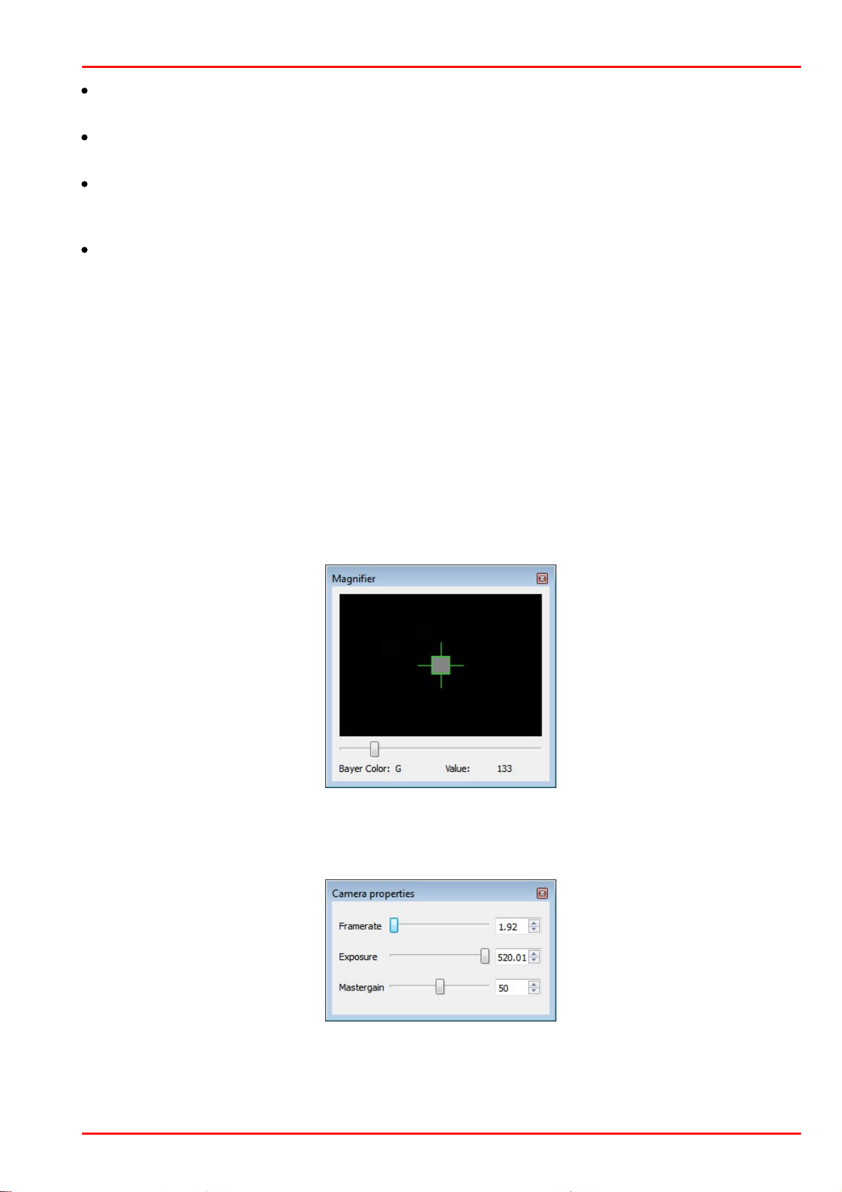
3 Operation
Add Badpixel
Writes the marked hot pixel in the hot pixel list of the program.
Delete Badpixel
Deletes a hot pixel from the hot pixel list of the program.
Highlight
Mark bad pixel with a circle in order to improve localization. Yellow marker stands for a factory
calibrated bad pixel, green marker - for user defined bad pixel.
1:1
Zoom factor of the shown image.
Camera and bad pixel list
Tab Camera List:
Recognized cameras are shown with status in the camera list. Via the context menu (right click to
the appropriate camera), a camera can be opened and closed. Cameras with the status "in use"
cannot be opened.
Tab Badpixel List:
In the bad pixel list the coordinates and the class of bad pixels are displayed.
Class "user": added by the user
Class "ignore": factory calibrated hot pixels
Magnifier function
The magnifier allows to exactly mark hot pixels. "Value" displays the relative pixel intensity.
Camera properties
Here, the camera settings can be changed for a better hot pixels visualization. By default, exposure
time is set to max. and master gain to 50. Note that the frame rate is limited to lower values.
© 2016 Thorlabs Scientific Imaging
83

DCx Camera Functional Description and SDK Manual
Detecting hot pixel automatically
opens the "Badpixel detection" dialog. Bad pixels are detected and can be added to
the "user" class list.
"Threshold": Any pixel with an intensity exceeding that threshold will be recognized as a bad (hot)
pixel, where the threshold is is the minimum intensity difference to the reference intensity. The
reference is the averaged over the most recent 10 frames total pixel intensities. Threshold can be
set between 5 and 255.
The "Clear old badpixel list" option removes the old user list before the search.
Note
The number of bad pixels, stored to the EEPROM, is limited. If the number of detected bad pixels
exceeds the memory capacity, please increase the bad pixel detection threshold and repeat the
detection procedure.
© 2016 Thorlabs Scientific Imaging84

4 Programming (SDK)
4 Programming (SDK)
In addition to the drivers, the uc480 software Development Kit (SDK) includes the uc480 Camera
Manager, the uc480 Viewer and the uc480 API programming interface for creating your own DCx
programs under Windows and Linux. Numerous demo applications make it easy for you to get
started with programming. The uc480 API offers you over 150 commands with which you can
access all the parameters and functions of your DCx camera. This chapter contains all the
information you need to integrate the DCx camera in your own applications using the uc480 API.
Note
Older Functions
We are continuously extending and enhancing the uc480 API. The resulting product upgrades
sometimes require replacing obsolete functions with new ones. If it is necessary to continue
working with the older functions, it is possible to add the uc480_deprecated.h header file
additionally to the ueye.h header file. The uc480_deprecated.h header file contains all obsolete
function definitions and constants which are no longer part of the ueye.h header file.
See also:
First steps to uc480 programming
How to proceed
Function descriptions
AVI function descriptions
Obsolete functions
Programming notes
Lists
© 2016 Thorlabs Scientific Imaging
85

DCx Camera Functional Description and SDK Manual
Select a display mode
The uc480 API provides different modes you can use to display the camera's images on
the PC. To quickly show a live image under Windows, it is easiest to use the Direct3D
mode. Under Linux the OpenGL mode can be used.
This mode has the advantage that no image memory has to be allocated, and that
image capture is handled by the driver. Call is_SetDisplayMode() to select the display
mode. You can then customize the Direct3D mode by using is_DirectRenderer().
For advanced users:
You can also access the image data directly by selecting the Bitmap (DIB) mode. To use
DIB mode, you first have to allocate one or more memories by using
is_AllocImageMem(), add them to a memory sequence, if required, and then activate a
memory with is_SetImageMem() before each image capture. To show the image on-
screen, call the is_RenderBitmap() function after each completed image capture. From
the events or messages you can see when an image is available for display.
See also:
How to proceed: Display mode selection
Capture images
Recording live images with the DCxCamera is very simple. Just call the
is_CaptureVideo() function and the camera captures the live images at the default
frame rate. To capture single frames, use the is_FreezeVideo() function. Every DCx
camera of course also provides different trigger modes for image capture. Use
is_SetExternalTrigger() to activate the desired mode before starting the image
capture.
See also:
How to proceed: Image capture
Adjust the frame rate, brightness and colors
To change the frame rate, for example, you call is_SetFrameRate(). With
is_SetColorMode() you set the color mode. Image brightness is adjusted through the
exposure time set with is_Exposure(). You can also implement automatic control of
image brightness and other parameters by using is_SetAutoParameter().
If you are using a color camera, you should activate color correction in order to achieve
rich vibrant colors for on-screen display (is_SetColorCorrection()). To adapt a color
camera to the ambient light conditions, it is essential to carry out white balancing. This is
also done using the is_SetAutoParameter() function.
See also:
How to proceed: Setting camera parameters
4.1 First Steps to uc480 Programming
This chapter shows the most important functions of the uc480 API for integrating your camera into
your own applications. You will find comprehensive lists of the API functions, sorted by task, in the
How to proceed chapter.
The uc480 SimpleLive and uc480 SimpleAcquire C++ programming samples included in the SDK
illustrate the steps described below.
For information on required include files (uc480 API and header) see Programming notes chapter.
© 2016 Thorlabs Scientific Imaging86

4 Programming (SDK)
Save an image
Use the is_ImageFile() function to save the current image as a BMP or JPEG file. To
save a specific image, it is better to use the Snap function (single frame mode) than the
Live function (continuous mode).
See also:
How to proceed: Saving images and videos
Close the camera
When you want to exit your application, close the camera with is_ExitCamera(). The
camera and the allocated memory are automatically released. All previously set camera
parameters will be lost, however. So, if you want to save specific settings, use the
is_ParameterSet() function before closing the camera. The next time you start the
application, you can simply load the settings again by using the same function.
© 2016 Thorlabs Scientific Imaging
87
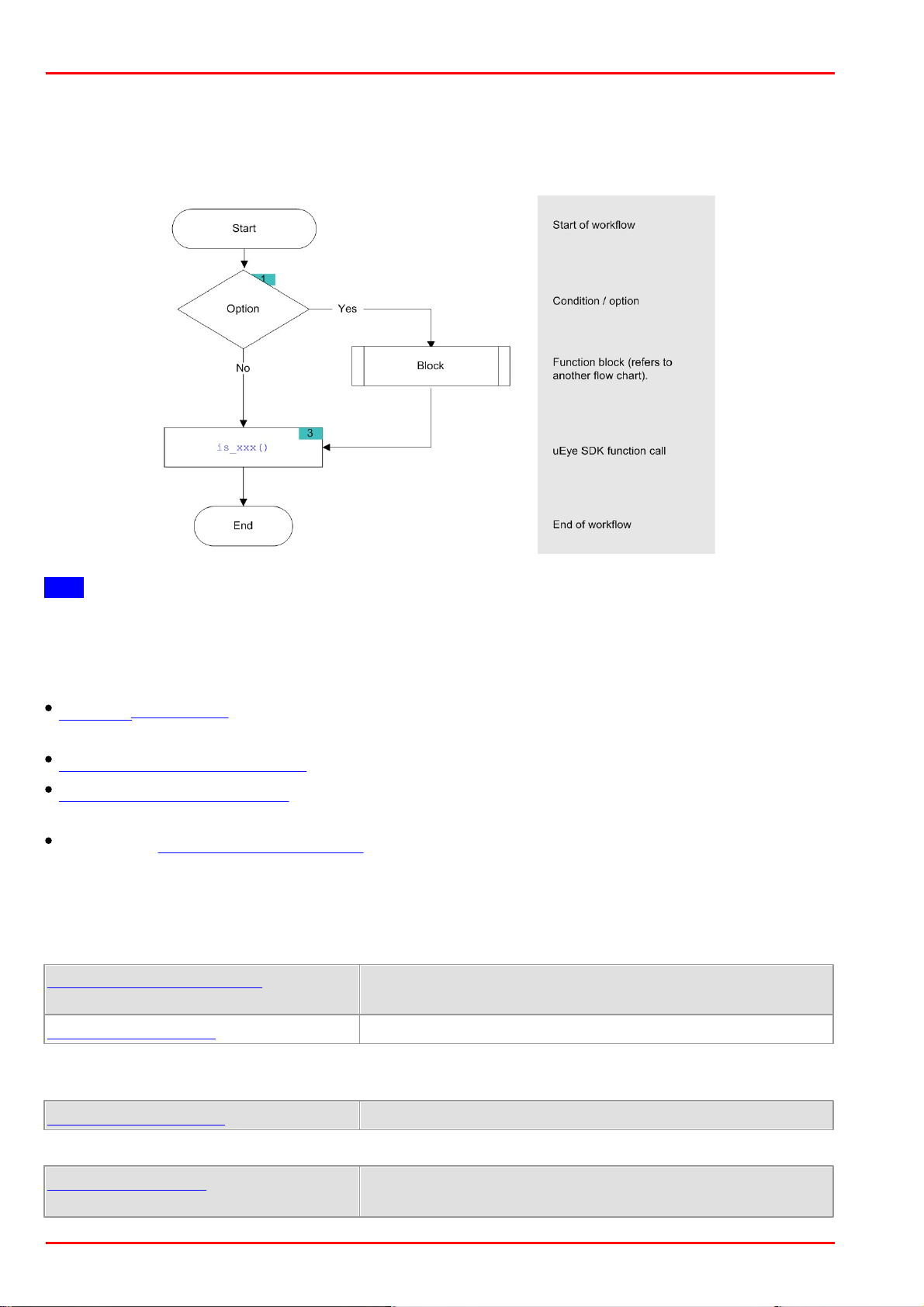
DCx Camera Functional Description and SDK Manual
is_GetNumberOfCameras()
Determines the number of cameras connected to the
system.
is_GetCameraList()
Returns information on all connected cameras.
is_SetErrorReport()
Enables/disables dialog messages for error output.
is_CameraStatus()
Returns the event counters and other information.
Enables standby mode.
4.2 How to Proceed
This chapter shows function blocks and workflows for important camera functions. The charts are
structured as follows:
Hint
Click the function names in the flowcharts to open the corresponding function description!
4.2.1 Preparing Image Capture
Querying information: Before you open one or more DCx Cameras, we recommend querying
some key information.
Opening and closing a camera
Allocating an image memory: This is necessary if you want to access image memory contents or
if you are not using Direct3D or OpenGL for image display.
Creating an image memory sequence is required when capturing live images.
4.2.1.1 Querying Information
It is recommended to query the following important information before opening one or more DCx
Cameras.
It is also very useful to have the message boxes for error output enabled during the programming
process
With the following functions, you can read out additional information on cameras and software.
© 2016 Thorlabs Scientific Imaging88

4 Programming (SDK)
is_GetCameraInfo()
Returns the camera information of an opened camera.
is_GetDLLVersion()
Returns the version of the uc480.dll.
is_GetOsVersion()
Returns the operating system version.
is_InitCamera()
Hardware initialization
is_ExitCamera()
Closes the camera and releases the created image memory.
is_SetCameraID()
Sets a new camera ID.
is_AllocImageMem()
Allocates an image memory.
is_SetAllocatedImageMem(
)
The user provides pre-allocated memory for image capturing.
is_FreeImageMem()
Releases an allocated image memory.
is_SetImageMem()
Makes an image memory active.
is_CopyImageMem()
Copies the image to the user-defined memory.
is_CopyImageMemLines()
Copies selected image lines to the user-defined memory.
is_GetActiveImageMem()
Returns the number and address of the active image memory.
is_GetImageMem()
Returns the pointer to the starting address of the image memory.
is_GetImageMemPitch()
Returns the line offset used in the image memory.
is_InquireImageMem()
Returns the properties of an image memory.
4.2.1.2 Opening and Closing the Camera
The following functions are required to open and close a DCx camera.
When multiple cameras are used on one system you should assign every camera a unique camera
ID.
4.2.1.3 Allocating Image Memory
When you are programming an application that
requires direct access to the image data in stored in memory, or
uses Bitmap mode (DIB) for display
use the following functions to allocate and manage image memories (see also Quick start: Image
display).
An image memory has to be activated before each image capture:
To query image memory information and access the data in the image memories, you can use
these functions:
Note
Image memory sequences should be used for frame sequence capture.
© 2016 Thorlabs Scientific Imaging
89
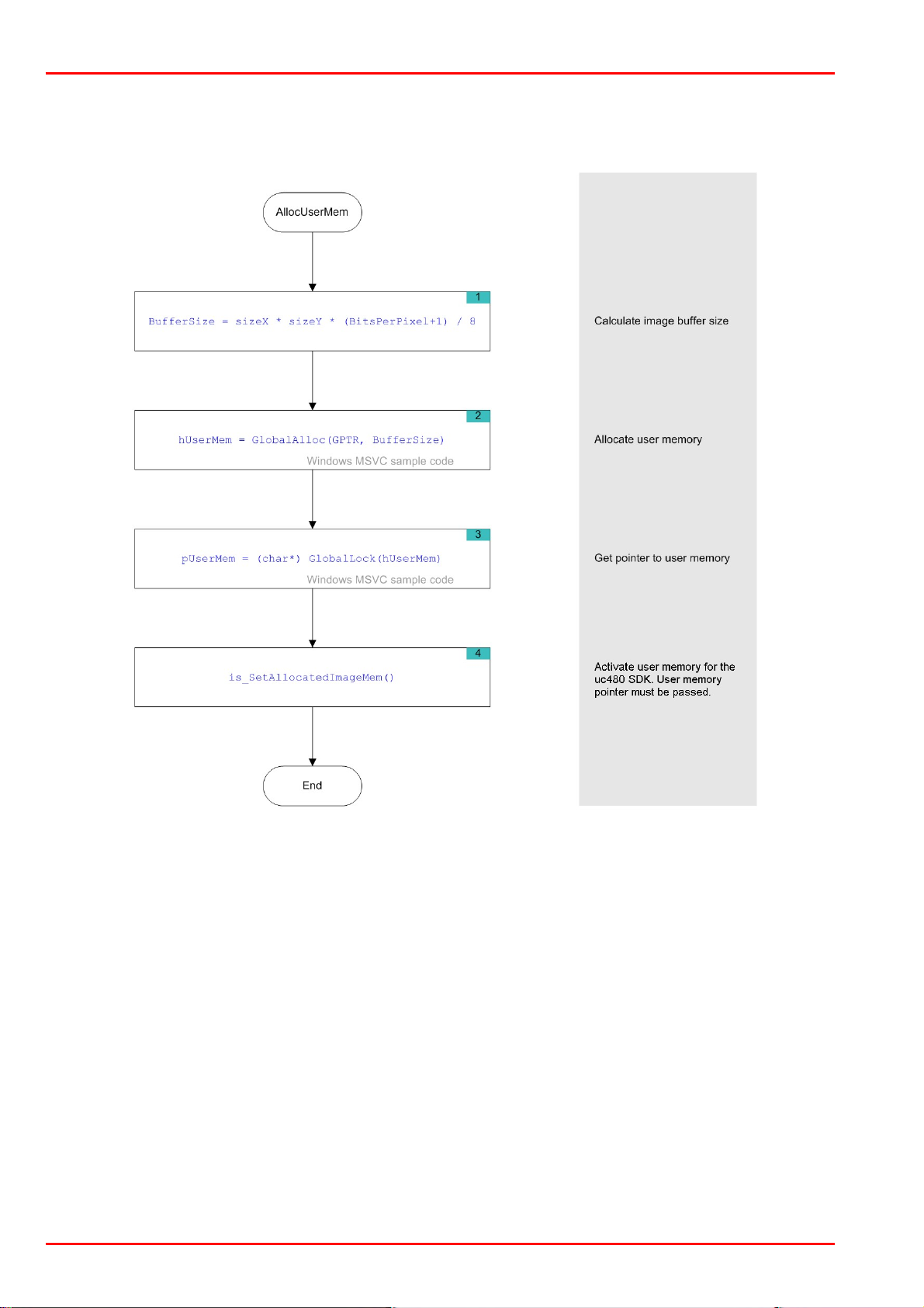
DCx Camera Functional Description and SDK Manual
Flowchart: Allocating memory
Click in the figure to get help on the functions.
© 2016 Thorlabs Scientific Imaging90

4 Programming (SDK)
is_AddToSequence()
Adds image memory to the sequence list.
is_ClearSequence()
Deletes the entire sequence list.
is_GetActSeqBuf()
Determines the image memory currently used for the sequence.
is_SetImageMem()
Makes the indicated image memory the active memory.
is_LockSeqBuf()
Protects the sequence image memory from being overwritten.
is_UnlockSeqBuf()
Releases the sequence image memory for overwriting.
4.2.1.4 Image Memory Sequences
When you are capturing and displaying frame sequences (e.g. live display), it is advisable to
provide appropriate image memory sequences. The uc480 driver offers a set of easy-to-use
features for this purpose. For example, the system automatically cycles through the specified
sequence of image memories and can generate an event when it reaches the end of a sequence
cycle.
Before you can use a memory sequence, you have to allocate the relevant image memories (see
Allocating image memory).
© 2016 Thorlabs Scientific Imaging
91

DCx Camera Functional Description and SDK Manual
is_SetDisplayMode()
Selection of the display mode.
is_RenderBitmap()
Outputs the contents of the active image memory to a window.
is_SetDisplayPos()
Enables offsetting the image output inside the window.
4.2.2 Selecting the Display Mode
Note
The uc480 driver provides different modes for displaying the captured images. We recommend
using the Bitmap mode or the Direct3D functions (only Windows) or OpenGL functions, depending
on your specific application.
For further information on the different display modes, see Basics: Image display modes.
Select the desired mode. The display mode has to be set before you start image capture.
When Bitmap mode (DIB) is active, image display has to be called explicitly for each image.
Flowchart: Image display in DIB mode
Click in the figure to get help on the functions.
© 2016 Thorlabs Scientific Imaging92

4 Programming (SDK)
4.2.3 Capturing Images
DCx Cameras support the capture of single frames (snap) and frame sequences (live) in trigger
mode and untriggered (freerun) mode. Select the image capture mode that best meets your
application requirements.
Using events or messages, the uc480 driver can provide information to an application, e.g. about
the completion of image capture. You will need events and messages, for example, when you are
using image memory sequences.
4.2.3.1 Image Capture Modes
For more information on the capture modes of the DCx Cameras see also Camera basics:
Freerun and Camera basics: Trigger.
Freerun mode
In freerun mode, the camera sensor captures one image after another at the set frame rate.
Exposure of the current image and readout/transfer of the previous image data are performed
simultaneously. This allows the maximum camera frame rate to be achieved. The frame rate and
the exposure time can be set separately. The captured images can be transferred one by one or
continuously to the PC.
If trigger mode is active, you need to disable it with is_SetExternalTrigger() before activating
freerun mode.
Single frame mode (snap mode)
When is_FreezeVideo() is called, the next image exposed by the sensor is transferred. You
cannot use the DCxCamera flash outputs in this mode.
Continuous mode (live mode)
When is_CaptureVideo() is called, images are captured and transferred continuously. You can
use the DCxCamera flash outputs.
Trigger mode
In trigger mode, the sensor is on standby and starts exposing on receipt of a trigger signal. A
trigger event can be initiated by a software command (software trigger) or by an electrical signal
via the camera’s digital input (hardware trigger). For the specifications of the electrical trigger
signals, see the Specifications: Electrical specifications chapter.
The trigger mode is selected using is_SetExternalTrigger().
Software trigger mode
When this mode is enabled, calling is_FreezeVideo() immediately triggers the capture of an
image and then transfers the image to the PC. If is_CaptureVideo() is called, the triggering of
image capture and the transfer of images are performed continuously.
Hardware trigger mode
When this mode is enabled, calling is_FreezeVideo() makes the camera ready for triggering just
once. When the camera receives an electrical trigger signal, one image is captured and
transferred.
If you call is_CaptureVideo(), the camera is made ready for triggering continuously. An image is
captured and transferred each time an electrical trigger signal is received; the camera is then
ready for triggering again (recommended procedure).
Freerun synchronization
In this mode, cameras running in freerun mode (live mode, see above) can be synchronized with
an external trigger signal. The cameras still remain in freerun mode. The trigger signal stops and
restarts the current image capture process. You can use this mode to synchronize multiple
© 2016 Thorlabs Scientific Imaging
93

DCx Camera Functional Description and SDK Manual
cameras that you are operating in the fast live mode. Not all camera models support this mode
(see is_SetExternalTrigger()).
Notes
The freerun synchronization mode is currently not supported by DCx Cameras.
In trigger mode, the maximum frame rate is lower than in freerun mode because the sensors
expose and transfer sequentially. The possible frame rate in trigger mode depends on the
exposure time.
Example: At the maximum exposure time, the frame rate is about half as high as in freerun mode;
at the minimum exposure time, the frame rate is about the same.
© 2016 Thorlabs Scientific Imaging94

Overview on image capture modes
Image
capture
Trigger
Function calls
Allowed flash
modes
Frame rate
Standard
Global
Start
Continuous
Off
is_SetExternalTrigger
(OFF)
is_CaptureVideo()
X
Freely selectable
Software
is_SetExternalTrigger
(SOFTWARE)
is_CaptureVideo()
X
X
Depending on exposure
time and trigger delay
Hardwar
e
is_SetExternalTrigger
(e.g. HI_LO)
is_CaptureVideo()
X
X
Depending on exposure
time and trigger delay
Freerun
sync.
is_SetExternalTrigger
(e.g. HI_LO_SYNC)
is_CaptureVideo()
X
Freely selectable
Single
frame
Off
is_SetExternalTrigger
(OFF)
is_FreezeVideo()
Freely selectable
Software
is_SetExternalTrigger
(SOFTWARE)
is_FreezeVideo()
X
X
Depending on exposure
time and trigger delay
Hardwar
e
is_SetExternalTrigger
(e.g. HI_LO)
is_FreezeVideo()
X
X
Depending on exposure
time and trigger delay
4 Programming (SDK)
Timeout values for image capture
When you call is_FreezeVideo() or is_CaptureVideo(), the timeout value for the image capture is
determined from the Wait parameter. If no image arrives within this timeout period, a timeout error
message is issued. Under Windows, a dialog box is displayed if you have enabled error reports
(see is_SetErrorReport()). Information on the error cause can be queried using
is_CaptureStatus().
© 2016 Thorlabs Scientific Imaging
95

DCx Camera Functional Description and SDK Manual
Parameter
Wait
Image capture
mode
Function
returns
Timeout for 1st image
Timeout for subsequent
images
*1
IS_DONT_WAIT
HW trigger
Immediately
API default or userdefined value
*3
API default or userdefined value
*3
IS_WAIT
HW trigger
When 1st
image in
memory
API default or userdefined value
*3
API default or userdefined value
*3
Time t
Value range
[4…
429496729]
HW trigger
When 1st
image in
memory
Time t in steps of 10 ms
(40 ms to approx. 1193 h)
API default or userdefined value
*3
IS_DONT_WAIT
Freerun/SW
trigger
Immediately
Calculated internally by
API
*2
Calculated internally by
API
*2
IS_WAIT
Freerun/SW
trigger
When 1st
image in
memory
Calculated internally by
API
*2
Calculated internally by
API
*2
Time t
Value range
[4…
429496729]
Freerun/SW
trigger
When 1st
image in
memory
Time t in steps of 10 ms
(40 ms to approx. 1193 h)
Calculated internally by
API
*2
is_CaptureVideo()
Captures a live video.
is_FreezeVideo()
Captures an image and writes it to the active image memory.
is_ForceTrigger()
Forces image capture in hardware trigger mode.
is_HasVideoStarted()
Returns whether the capture process has been started or not.
is_IsVideoFinish()
Returns whether the capture process has been terminated or not.
is_SetSensorTestImage()
Enables test image output from sensor (all cameras).
is_StopLiveVideo()
Terminates the capturing process (live video or single frame).
The following table shows the effect of the Wait parameter depending on the image capture mode:
*1 Only with continuous image capture using is_CaptureVideo()
*2 The timeout is calculated from the exposure time setting, the image transfer time (depending on
the pixel clock) and the optional trigger delay (see is_SetTriggerDelay()); it is at least 40 ms.
*3 The default value of the uc480 API is 60 s. User-defined values can be set using the
is_SetTimeout() function.
Function list
© 2016 Thorlabs Scientific Imaging96

Flowchart: Single Capture
Flowchart - Single Capture (1 of 2)
Click in the figure to get help on the functions.
4 Programming (SDK)
© 2016 Thorlabs Scientific Imaging
97

DCx Camera Functional Description and SDK Manual
Flowchart - Single Capture (2 of 2)
© 2016 Thorlabs Scientific Imaging98
 Loading...