


DC210, DC310
Firewire CCD Camera
ThorSight Image Acquisition
Software
Manual

Firewire CCD Camera
Table of Contents
Part 1. Thor Sight Software Guide ..........................................................................................................4
1.1. Image Capture .......................................................................................................................................... 4
1.2. Saving Individual Images ........................................................................................................................ 6
File Types: ................................................................................................................................................................. 6
1.3. Recording a Movie Clip to an AVI File .................................................................................................. 7
1.4. Camera Control Dialog Functions .......................................................................................................... 7
General Camera Properties ........................................................................................................................................ 8
Format and Frame Rate ............................................................................................................................................ 10
Custom Image .......................................................................................................................................................... 11
Info/Support ............................................................................................................................................................. 12
Register .................................................................................................................................................................... 13
Trigger ..................................................................................................................................................................... 14
White Balance .......................................................................................................................................................... 15
Color Processing ...................................................................................................................................................... 15
1.5. About Thor Sight.................................................................................................................................... 17
1.6. External Trigger Setup .......................................................................................................................... 17
Part 2. DC210 Technical Reference ......................................................................................................18
2.1. General Specifications ........................................................................................................................... 18
2.2. Camera Power ........................................................................................................................................ 18
2.3. Typical Spectral Response ..................................................................................................................... 19
2.4. Infrared Cut-Off Filters ........................................................................................................................ 20
2.5. Analog to Digital Converter .................................................................................................................. 21
Part 3. Camera Operation and Features ...............................................................................................22
3.1. Gain and Shutter Settings ..................................................................................................................... 22
Gain.......................................................................................................................................................................... 22
Shutter ...................................................................................................................................................................... 22
Extended Shutter ...................................................................................................................................................... 23
3.2. Camera Interface ................................................................................................................................... 24
General Purpose IO .................................................................................................................................................. 24
IEEE-1394 Connector .............................................................................................................................................. 24
3.3. Automatic Inter-Camera Synchronization .......................................................................................... 25
3.4. Supported Data Formats and Modes ................................................................................................... 25
Standard Formats, Modes and Frame Rates ............................................................................................................. 25
Customizable Formats and Modes ........................................................................................................................... 25
Image Data Formats ................................................................................................................................................. 26
Mechanical Specifications ....................................................................................................................................... 27
Part 4. Regulatory ..................................................................................................................................28
Part 5. Thorlabs, Inc Worldwide Contacts ............................................................................................29
13141-D02 Rev B, March 1, 2010 Page 2 www.thorlabs.com

Firewire CCD Camera
Table of Figures
Figure 1: Select Camera Dialog Box ..................................................................................................... 4
Figure 2: Thor Sight Main Screen and Tool Bar ................................................................................... 5
Figure 3: Image from a DC210 ............................................................................................................. 6
Figure 4: General Camera Properties Tab ............................................................................................. 9
Figure 5: Format and Frame Rate Tab ................................................................................................ 10
Figure 6: Custom Image Tab ............................................................................................................... 11
Figure 7: Info/Support Tab .................................................................................................................. 13
Figure 8: Register Tab ......................................................................................................................... 14
Figure 9: White Balance Tab ............................................................................................................... 15
Figure 10: Color Processing Tab ........................................................................................................... 16
Figure 11: Thor Sight About Dialog Box .............................................................................................. 17
Figure 12: Thor Sight External Trigger Parameters Dialog Box .......................................................... 17
Figure 13: Spectral Response for DC210 .............................................................................................. 19
Figure 14: Spectral Response for DC210C ........................................................................................... 19
Figure 15: Spectral Response for DC310 .............................................................................................. 20
Figure 16: IEEE 1394 Connector .......................................................................................................... 25
Figure 17: Mechanical Drawing of the DCx10 Housing ....................................................................... 27
13141-D02 Rev B, March 1, 2010 Page 3 www.thorlabs.com

Firewire CCD Camera
Part 1. Thor Sight Software Guide
The Thor Sight application is a streaming image viewer used to interface with your DC210/DC310
camera. It allows you to view a live video stream from the camera, save individual images, save AVI
movie clips, trigger the camera to capture trigger-generated images, adjust camera settings, select
different frame rates, and access the camera registers.
1.1. Image Capture
Launch the Thor Sight executable from the desktop icon. The Select Camera dialog box (Figure 1) will
appear.
Figure 1: Select Camera Dialog Box
From the list of cameras, choose the one that you wish to use for image capture. Once the camera is
selected, click the “OK” button, and the main Thor Sight application window will open. If you wish to
change the camera that is being displayed, access the camera dialog box by clicking on the Camera
Dialog icon ( ), which is the leftmost icon on the toolbar.
13141-D02 Rev B, March 1, 2010 Page 4 www.thorlabs.com

Firewire CCD Camera
Trigger Logo Icon – External Trigger Setup
Thorlabs Logo Icon – Information about ThorSight
AVI Camera Icon – Creates an *.avi Movie Clip
Stop Light Icon – Stat and Stop Video Capture
Stop Sign Icon – Stops the Video Capture
Camera Property List Icon – Access Camera Controls
Save Icon – Saves a single Video Image
Camera Dialog Icon– Switch to a Different Camera
Figure 2: Thor Sight Main Screen and Tool Bar
To start capturing images, click the Stop Light icon ( ) on the toolbar. The video will be displayed in
the main Thor Sight window with the frame rate and timing information displayed in the lower status
bar.
To stop the image capture, click the Stop Light icon ( ) again. Alternatively, you can also click the Stop
Sign icon ( ).
13141-D02 Rev B, March 1, 2010 Page 5 www.thorlabs.com

Firewire CCD Camera
Figure 3: Image from a DC210
1.2. Saving Individual Images
To save a single video frame, click the Save icon ( ) on the toolbar. A save file dialog box will appear,
enabling you to save the image.
File Types:
1. Portable Pixelmap (*.ppm). PPM is a simple color image file format that can store pixel values
up to 24 bits in size. These images can be viewed and edited using Paint Shop Pro from Jasc
Software.
2. Bitmap (*.bmp). BMP are an extremely popular format for Windows. BMP images can range
from black and white (1 byte per pixel) up to 24 bit color (16.7 million colors), and can be
viewed by most image viewers especially Microsoft Paint.
3. Portable Gray Map (*.pgm). PGM format is a simple grayscale file format. It is designed to be
extremely easy to learn and write programs for, and is capable of storing 16 bit images. Paint
13141-D02 Rev B, March 1, 2010 Page 6 www.thorlabs.com

Firewire CCD Camera
Shop Pro from Jasc Software is a good image editor that can open and display .pgm images. The
Linux application XV is the only application know to handle 16 bit images.
4. Raw (*.raw). Raw image files contain no header or footer information, and are the basic raw
data (pixel values) represented by the image.
1.3. Recording a Movie Clip to an AVI File
Thor Sight allows you to save a specified number of images as an Audio Video Interleave (.avi) movie
clip. To access this functionality, stop the camera then click the AVI Camera icon ( ) on the toolbar. A
dialog box similar to the one below will appear:
• The Frames field is the number of images that will make up the AVI. Each image is allocated its
own buffer in main memory which will limit the number of frames that can be specified.
• The Frame rate override controls the playback rate of the AVI. If this is left as 0, the playback
rate defaults to the image grab rate of the camera (i.e. 30 Hz). This is useful for creating slow
motion video.
• The Path field specifies the directory path and filename of the saved AVI file. The default
directory and filename is: C:\Thorsight\thorsight.avi.
1.4. Camera Control Dialog Functions
The Camera Control dialog box allows you to manipulate most camera properties, check camera
information and allows you to directly access camera hardware registers to get and set specific register
values.
To access the Camera Control dialog click the Camera Property List icon ( ) on the toolbar. Some of
the controls in the camera dialog box may be grayed out. This means that the camera being used does
not support that functionality. There are eight register tabs on the camera control dialog. Each tab will be
discussed below.
13141-D02 Rev B, March 1, 2010 Page 7 www.thorlabs.com

Firewire CCD Camera
General Camera Properties
Property Description
Brightness (%) This is the level of black in an image. A high brightness will result in a low amount of
blackness in the image.
Saturation This is how far a color is from a gray image of the same intensity, i.e. red is highly saturated,
where as a pale pink is not.
Exposure (EV) This is the average intensity of the image. It will use other available (non-manually adjustable)
controls to adjust the image. Specifically, when shutter and gain are both in auto mode,
manually adjusting the exposure slider control is actually adjusting the auto-exposure, which
tries to make the average intensity of the image ¼ of the auto exposure value, i.e. exposure is
400, the camera will try to adjust shutter and gain so that the average image intensity is 100.
When the auto checkbox is checked for exposure, auto-exposure is enabled, which tries to
manipulate shutter and gain such that a percentage of the image is saturated, i.e. pixel value of
255.
Gain (dB) The amount of amplification that is applied to a pixel. An increase in gain can result in a
brighter image and an increase in noise.
Gamma Gamma defines the function between incoming light level and output picture level. Gamma
can also be useful in emphasizing details in the darkest and/or brightest regions of the image.
Sharpness This works by filtering the image to reduce blurred edges in an image.
Shutter (ms) This is the amount of time that the camera shutter stays open for; also know as the integration
time.
Frame Rate This is the speed at which the camera is streaming images to the host system. It basically
defines the interval between consecutive image transfers.
13141-D02 Rev B, March 1, 2010 Page 8 www.thorlabs.com

Firewire CCD Camera
Figure 4: General Camera Properties Tab
Some general properties will have an Auto Mode in which the camera will automatically make property
adjustments to get the best image possible (given the environment and lighting conditions). Some
properties can also be turned On/Off, effectively disabling the property control. The One Push button is
another automatic control mode, but the camera only performs automatic control of the feature for a
specific period of time. After this time, automatic setting adjustment stops and manual control is given
back to the user.
General camera property values can be displayed in either absolute mode or integer mode. Absolute
values are real world values, such milliseconds (ms), decibels (dB) or percent (%). Using the absolute
values is easier and more efficient than applying complex conversion formulas to the integer values. In
addition, these conversion formulas can change between firmware versions, Thorlabs therefore
recommends using the absolute values to determine camera values.
The Broadcast Modifications checkbox allows you to broadcast the current camera’s settings to other
cameras of the same type that are on the same 1394 bus. Checking this and making a change to your
current DCx10’s gain settings will cause other DCx10s on the same Fire Wire bus to have the same gain
settings. Clicking the Broadcast Properties button causes all current camera settings to be sent one time
only to all compatible cameras on the Fire Wire bus.
13141-D02 Rev B, March 1, 2010 Page 9 www.thorlabs.com

Firewire CCD Camera
Thor Sight also provides the ability to save and restore all general camera properties to and from the
system registry using the Save and Restore buttons. The specific location these settings are saved to is:
HKEY_CURRENT_USER\Software\Thorlabs, Inc.\Camera Settings\
Relevant Camera Registers:
Control and Status Registers for Features: 800h->83Ch
Format and Frame Rate
On the Format and Frame Rate tab you can change the resolution (horizontal and vertical pixel
dimensions), image format (i.e. Y8, RGB, YUV422, etc.) and frame rate (number of frames of
transmitted per second) of the camera. Different cameras may have different formats and frame rates
implemented; modes that are not implemented are grayed out. These modes conform to IEEE-1394
Digital Camera specifications.
Relevant Camera Registers
Control and Status Registers for Features: 600h->630h
13141-D02 Rev B, March 1, 2010 Page 10 www.thorlabs.com
Figure 5: Format and Frame Rate Tab

Firewire CCD Camera
Custom Image
The Custom Image tab provides and interface for putting the camera into Format 7, which is a partial
image video mode. Some custom image modes allow faster frame rates due to the reduced amount of
data (bytes per packet) being transmitted by the camera to the host system.
13141-D02 Rev B, March 1, 2010 Page 11 www.thorlabs.com
Figure 6: Custom Image Tab

Firewire CCD Camera
Property Description
Mode Most DCx10s allow you to capture custom sized images using a variety of IEEE-1394 DCAM-
compliant Format 7 custom image modes.
Image Size/Position The custom image dimensions are relative to the top left corner of the image sensor. The top left
corner is given coordinates (column 0, row 0). The custom image size must be evenly divisible
by the Unit Size and less than or equal to the Max Image Size. For example, a size of 120(width)
x 60(height) in Mode 0 is correct – 4 divides evenly into 120, and 4 divides evenly into 60.
Pixel Format The Pixel Format is used to indicate the color-coding capability of the camera. Raw8 and Raw16
images will be color processed and displayed as color in Thor Sight. Specifying Mono8 or
Mono16 for a color camera effectively disables color processing, and the raw stippled Bayer
images will be displayed.
Speed The Speed section contains two interfaces into controlling the effective frame rate of the camera
while in Custom Image (Format 7) mode. The traditional method is via the Speed slider bar,
which sets the number of bytes per packet to be a percentage of the maximum possible bytes per
packet. The more bytes of image data that can be sent in each packet, the faster the frame rate.
The other method is by manually controlling the Packet Size (in bytes). As values are entered in
the Image Size/Position text fields, the minimum and maximum bytes per packet are
automatically updated.
Info/Support
The Info/Support tab provides information about the camera, installed Thor Sight software, and links to
technical support resources.
13141-D02 Rev B, March 1, 2010 Page 12 www.thorlabs.com

Firewire CCD Camera
Figure 7: Info/Support Tab
Property Description
Camera Information The camera information displayed includes the version of firmware that is loaded onto the
camera, the camera serial number, model name, and type of image sensor. Firmware is
programming that is inserted into programmable read only memory, thus becoming a permanent
part of a computing device. Firmware is created and tested like software and can be loaded onto
the camera.
Software Information The software displayed includes version information for Thor Sight, the DLL’s being used by the
current instance of Thor Sight and the version number of the driver currently being used by the
camera.
Technical Support Thorlabs, Inc. provides technical support resources by calling our tech support number 973-579-
7227.
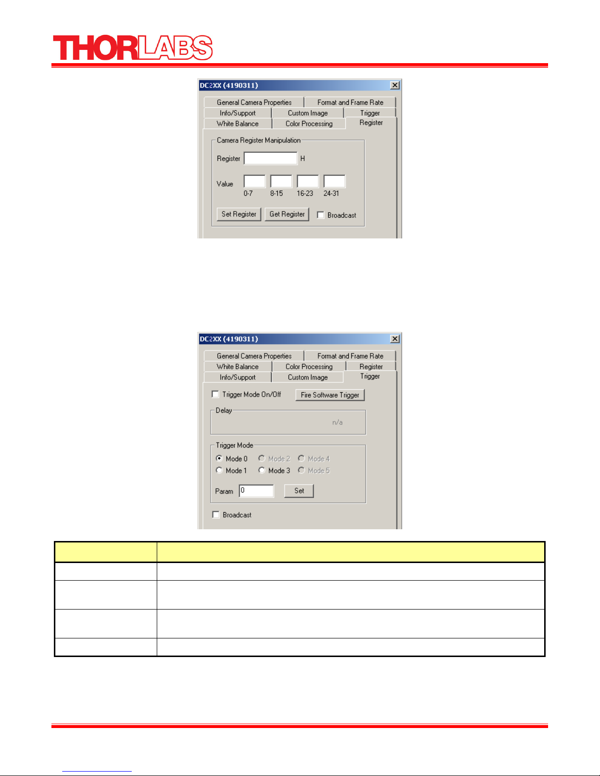
Register
The Register tab provides direct access to camera registers, and is recommended for advanced users.
When the Broadcast checkbox is checked, any register writes are broadcast to all cameras on the same
1394 bus.
13141-D02 Rev B, March 1, 2010 Page 13 www.thorlabs.com
Firewire CCD Camera
Figure 8: Register Tab
Trigger
The Trigger tab provides easy access to the camera’s asynchronous transmission modes, which are
implemented on the DCx10 line of cameras.
Property Description
Trigger Mode On/Off Checking the Trigger Mode On/Off checkbox turns on or off asynchronous transmission mode.
Delay This provides control over the time delay between an external asynchronous trigger and the
start of integration. (shutter opening)
Trigger Mode This defines the specific trigger mode the camera is in. Some triggers take a value that can be
set using the Param text box.
Fire Software Trigger This causes a software asynchronous trigger to be fired.
Relevant Camera Registers
TRIGGER_MODE: 830h
13141-D02 Rev B, March 1, 2010 Page 14 www.thorlabs.com

Firewire CCD Camera
TRIGGER_DELAY: 834h
SOFTWARE_TRIGGER: 62Ch
SOFT_ASYNC_TRIGGER: 102Ch
White Balance
This option is only available for color cameras. White Balance allows you to control the relative levels
of red and blue in an image to achieve proper color balance. Moving both red and blue values toward
zero should make the image appear greener. Green is kept as a constant and the red and blue
Colors are adjusted relative to the green pixel. Hardware white balance is actually performed prior to
the signal being digitized as it comes off of the sensor, which results in higher quality images. Selecting
the On/Off check box turns on or off white balance control – this functionality only works with cameras
that have recent versions of firmware.
Relevant Camera Registers
WHITE_BALANCE: 80Ch
BAYER_TILE_GAIN:1044Ch
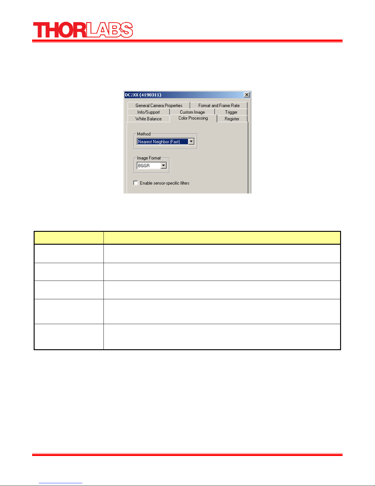
Color Processing
The option is only available for color cameras. For most DC210C color cameras, the conversion of the
Bayer Tiled images produced by the image sensor into color takes place on the PC, and not on the
camera itself. If there is no visible difference in the image quality when selecting different color
processing methods, your camera does not color process on the PC.
13141-D02 Rev B, March 1, 2010 Page 15 www.thorlabs.com
Figure 9: White Balance Tab
Firewire CCD Camera
Which color conversion process is more beneficial will depend on the application of the color
conversion. On-board conversion will take more bandwidth on the bus but less processor resources,
whereas PC conversion does not take as much bandwidth on the bus but will be more demanding of the
processors resources.
Figure 10: Color Processing Tab
The differences between the various color processing algorithms are as follows:
Property Description
Nearest Neighbor Faster This is the fastest of all of the provided color processing algorithms. It is generally considered
to provide the poorest results
Nearest Neighbor Fast Based on a very similar algorithm to the Nearest Neighbor Faster this algorithm is slower but
performs slightly better
Edge Sensing The algorithm is the second slowest algorithm available. The algorithm weights surrounding
pixels based on localized edge orientation.
Rigorous This algorithm is the slowest of all of the algorithms and, without a doubt produces the best
color quality. Rigorous image processing takes seconds, not microseconds, and is not meant
for real-time processing like the other algorithms
Image Format The Image Format is the orientation of the Bayer Tiling on your image sensor. This will
default to the correct Bayer Tiling. The Enable sensor-specific filters checkbox only applies
to some versions of the DCx10 cameras.
Relevant Camera Registers
BAYER_TILE_MAPPING: 1040h
13141-D02 Rev B, March 1, 2010 Page 16 www.thorlabs.com

Firewire CCD Camera
1.5. About Thor Sight
To Learn about Thor Sight, click the Thorlabs Logo icon ( ).
Figure 11: Thor Sight About Dialog Box
1.6. External Trigger Setup
1. To Set up the external trigger capture, click the Trigger Logo icon ( ).
The Trigger parameters dialog box will appear:
Figure 12: Thor Sight External Trigger Parameters Dialog Box
Property Description
Trigger Timeout (ms) The time the camera will wait to receive an external trigger on the input pins. A trigger is
generated by a low going pulse between the trig pin and gnd on the external trigger
connector. A flying lead cable is included for convenience
Number of Images The number of images that will be saved. Each image will require a pulse, i.e. 10 images will
require 10 pulses.
Thor Sight Image This path field specifies the directory path and filename of the saved images. Multiple images
will be incremented from 0 to number of images saved, i.e. thorsightimage00.bmp,
thorsightimage01.bmp
Arm Button Click to have the camera begin waiting for the trigger.
13141-D02 Rev B, March 1, 2010 Page 17 www.thorlabs.com

Firewire CCD Camera
Part 2. DC210 Technical Reference
The DC210/DC310 is a compact CCD camera suitable for a variety of end user applications. This
section of the manual attempts to provide the user with a detailed specification of the DC210 camera.
2.1. General Specifications
Specification DC210 DC310
Style CCD camera in Black aluminum housing
with flying lead cable for external triggering
Sensor Sony 1/3" Type Sony HAD CCD
ICX084/ICX424
Resolution 640x480 1024x768
A/D Converter Analog Devices AD9841A A/D n/a
Video Output Signal 8 bits/pixel, 10 bits/pixel Digital Data
Interfaces 6-Pin IEEE-1394 for camera control and video data transmission 6 pin digital I/O
connector with flying lead cable
Voltage Requirements 8-32V
Power Consumption Less than 2W
Frame Rates 3.75,7.5,15,30 fps 1.875,3.75,7.5,15 fps
Gain Automatic/Manual Modes
0 dB through 30 dB
Shutter Automatic/Manual/Extended Shutter modes
1/30 s to 1/8000 s @30 Hz
Signal to Noise Ratio 50 dB or better at minimum gain
External Trigger DCAM v1.30 Trigger_Mode_0
CCD camera in Black aluminum housing
with flying lead cable for external triggering
Sony 1/3" Type Sony HAD CCD ICX204
0 dB through 27 dB
Automatic/Manual/Extended Shutter modes
1/15 s to 1/6000 s @15 Hz
Dimensions 2.86 x 2.13 x 0.7 inches
Lens Adapter Thorlabs DCM1 C mount adapter or DCSM1 CS Mount adapter
Camera Specification IIDC 1394-based Digital Camera Specification v1.30
Operating Temperature Commercial Grade Electronics rated from 0 to 70 ºC
Storage Temperature Room Temperature
Camera Upgrades Please visit our website: www.thorlabs.com
FCC Compliance The DC210 and DC310 comply with Part 15 of FCC Rules. Operation is subject to the
following two conditions: (1) this device may not cause harmful interference; and (2) this
device must accept any interference received, including interference that may cause
undesired operation.
2.2. Camera Power
The 6 pin 1394 connector connects to a standard IEEE 1394 (Fire Wire) 6 pin cable and provides the
camera with both power and a connection to your computer. The ideal input voltage is 12V DC;
13141-D02 Rev B, March 1, 2010 Page 18 www.thorlabs.com

Firewire CCD Camera
however, the camera is designed to handle voltages between 8 V and 32 VDC according to the IEEE
1394 standard. The power consumption of the DCx10 is less than 2 W at 12 VDC.
Some 1394 PCMCIA cards fro laptop / notebook computers require a 4 pin cable. A 4 pin cable does not
provide power and will therefore not work with the DCx10.
2.3. Typical Spectral Response
Figure 13: Spectral Response for DC210
Figure 14: Spectral Response for DC210C
13141-D02 Rev B, March 1, 2010 Page 19 www.thorlabs.com

Firewire CCD Camera
Figure 15: Spectral Response for DC310
2.4. Infrared Cut-Off Filters
The DC210C cameras have an additional infrared cut-off filter included. The approximate properties of
this filter are illustrated by the IRC30 curve in the graph below.
13141-D02 Rev B, March 1, 2010 Page 20 www.thorlabs.com

Firewire CCD Camera
2.5. Analog to Digital Converter
The DC210 incorporates an Analog Devices AD9841A A/D converter in order to digitize the images
produced by the CCD. The following table illustrates the most important aspects of the processor.
Specification Value
Resolution 10 bit
Pixel Gain Amplifier 4 ± 6 dB 6-bit
Variable Gain Amplifier 2 to 36 dB 10-bit
http://www.analog.com/static/imported-
Datasheets
files/data_sheets/AD9841A_9842A.pdf
13141-D02 Rev B, March 1, 2010 Page 21 www.thorlabs.com

Firewire CCD Camera
Part 3. Camera Operation and Features
3.1. Gain and Shutter Settings
This section describes how to convert Gain and Shutter settings from the format reported by the camera
into real world units.
Gain
The gain settings in the Thor Sight program can be converted to dB by using the following formula:
DC210 – 0 dB is 220
If G < 512
Gain = -6.0404 + [20*log((658+G)/(658-G))]
Else if G > 512
Gain = -6.0404 + [0.0354*G]
DC310 – 0dB is 325
If G < 512
Gain = -9.40 + [20*log((658+G)/(658-G))]
Else if G > 512
Gain = -9.40 + [0.0354*G]
G is the gain setting in the software. The absolute gain setting in dB of the camera can be read from the
CSR register at offset 928h. The returned number is in the IEEE floating point format.
Shutter
The shutter speed can be calculated using the following formulae:
DC210
T=(S*30) / (16000*F)
DC310
T=(S*15) / (12000*F)
13141-D02 Rev B, March 1, 2010 Page 22 www.thorlabs.com

Firewire CCD Camera
Where S is the setting in the camera control and F is the frame rate.
Extended Shutter
In special cases where the user has modified the EXTENDED_SHUTTER register at offset 1028h this
formula generalizes to the following:
T = (S*M) / (U*F)
M is the mode that the EXTENDED_SHUTTER register has been set to (30 for extended mode), and U
is the reciprocal of the units of the shutter setting
S
Mode
DC210
30 Hz 2 532 30 16000 0.469- 30 1/8000 s 0.468s
32 Hz 2 500 32 16000 0.5 32 1/8000 s 2s
Extended 2 4000 30 16000 0.469 30 1/8000 s 16s
50 Hz 2 256 50 12800 50 50 1/6400 s 1/50s
24 Hz 2 666 24 16000 0.375 24 1/8000 s 2.66s
DC310
15 Hz 2 800 15 12000 0.469 15 1/6000 s 1/30s
Extended 2 4000 15 12000 0.469 15 1/6000 s 10.66s
Min Max Min Max Min Max
M U
F Shutter Time
Extended shutter works as follows:
DC210 DC310 fps
16 NA 30
To calculate the shutter period in seconds:
Maximum number of line periods is given as 61344. this is the maximum we can send to register 0x81C,
so it has a range from 0 – 61344. To calculate a shutter period of 1 sec, we could do this in multiple
ways:
X/line rate(Hz) = shutter period (sec)
13141-D02 Rev B, March 1, 2010 Page 23 www.thorlabs.com
8 12 15
4 6 7.5
2 3 3.75
1 1.5 1.875

Firewire CCD Camera
Where X is the number of lines to wait
At 30 fps the X/line rate = 1 sec. At 30 Hz at DC210(640x480), the line rate is 16kHz so X/16000 = 1.
So the value you to set is 16000.
At 15 fps, X is 8000 for DC210.
At 7.5fps, X is 4000 for DC210
At 15 fps, X is 12000 for DC310
At 7.5 fps, X is 6000 for DC310
The maximum shutter period is 61344/1000 = 61.344 sec.
In extended shutter mode, the upper limit of 4000 (0x0Fa0) can be extended up to a maximum of
65440(0xFFA0) by simply writing to the high shutter bits [8-19] of the SHUTTER register.
3.2. Camera Interface
General Purpose IO
The DC210 comes with a flying lead cable which is used for general purpose IO. The leads are
configured to accept a input trigger signal on the trig and GND pins. The IO3 pin is configured to send a
strobe out of the DC210 to an external device
The DC210 IO pins are TTL 3.3V inputs protected by two diodes to +3.3V and GND in parallel. There
is also a 10K resistor in series to limit current. When configured as input, the pins can be directly driven
from a 3.3V or 5V logic output. For output, each IO pin has almost no drive strength (high impedance)
and needs to be buffered with a transistor or driver to lower its impedance.
IO1 is capable of powering external circuitry up to a total of 50 mA. The IO pins are protected from
both over and under voltage. It is recommended, however, that they only be connected to 5V or 3.3V
digital logic signals. It should be noted that TRIG pin has a weak pull up resistor to allow a shorting of
the pin to GND for triggering.
IEEE-1394 Connector
The DC210 has a standard 6-pin IEEE 1394 connector that is used for data transmission, camera control
and powering the camera.
13141-D02 Rev B, March 1, 2010 Page 24 www.thorlabs.com

Firewire CCD Camera
Pin Function
1 Power Input
2 DC GND
3 TPB-
4 TPB+
5 TPA-
6 TPA+
Figure 16: IEEE 1394 Connector
3.3. Automatic Inter-Camera Synchronization
Multiple DCx10s on the same IEEE 1394 bus are automatically synchronized to each other at the
hardware level. When using multiple cameras, the timing of one camera to another camera is as follows:
1. If the cameras are on the same bus, the cameras are synchronized to within 125 ms of each other
(125 ms is the maximum deviation). The 1394 bandwidth limits the maximum number of
cameras that can be on one bus.
2. If the cameras are on separate buses a Sync unit is needed to synchronize the buses. Please
contact technical support for information. Without the sync device there is no correlation
between separate cameras on separate buses.
3.4. Supported Data Formats and Modes
Standard Formats, Modes and Frame Rates
The following table enumerates the different data formats and modes contained in the IIDC 1394
specification that are supported by the DC210
Camera Format Mode Mode Frame Rate(fps) Mode Description
DC210
DC310
Customizable Formats and Modes
The following table outlines 1394 DCAM-compliant Format 7 custom image modes that are supported
by the DCx10 cameras. The frame rates specified, however, are not contained in the specification.
0 5 3.75,7.5,15,30 640 x 480 Y8 (Mono)
0 6 3.75,7.5,15,30 640 x 480 Y16 (Mono)
1 5 1.875,3.75,7.5,15 1024 x 768 Y8 (Mono)
1 7 1.875,3.75,7.5 1024 x 768 Y16 (Mono)
13141-D02 Rev B, March 1, 2010 Page 25 www.thorlabs.com

Firewire CCD Camera
Frame Rate
Camera Format Mode
7 0 30 Partial Image Format (sub-window) - allows the user to only
DC210
7 1 50 Partial Image Format (sub-sampled) - allows the user to
7 0 15 Partial Image Format (sub-window) - allows the user to only
DC310
7 1 25 Partial Image Format (sub-sampled) - allows the user to
(fps) Mode Description
transmit a selected area of the image. Although no speed
improvement is realized, this feature is useful for reducing
bandwidth requirements while maintaining frame rate.
transmit a sub-sampled 640 x 240 image at up to 50 fps
transmit a selected area of the image. Although no speed
improvement is realized, this feature is useful for reducing
bandwidth requirements while maintaining frame rate.
transmit a sub-sampled 1024 x 384 image at up to 25 fps
Image Data Formats
The following table illustrates the data format for the various modes.
Mode Data Format
Y8 8 bit/pixel 0-7 76543210
Y16 16 bit/pixel 0-7 High Byte 8-15 Low Byte this format can be toggled with the
Y16_DATA_FORMAT REGISTER 1048H
13141-D02 Rev B, March 1, 2010 Page 26 www.thorlabs.com

Mechanical Specifications
Firewire CCD Camera
Figure 17: Mechanical Drawing of the DCx10 Housing
13141-D02 Rev B, March 1, 2010 Page 27 www.thorlabs.com

Firewire CCD Camera
Part 4. Regulatory
As required by the WEEE (Waste Electrical and Electronic Equipment Directive) of the European
Community and the corresponding national laws, Thorlabs offers all end users in the EC the possibility
to return “end of life” units without incurring disposal charges.
• This offer is valid for Thorlabs electrical and electronic equipment:
• Sold after August 13th 2005
• Marked correspondingly with the crossed out “wheelie bin” logo (see)
• Sold to a company or institute within the EC
• Currently owned by a company or institute within the EC
• Still complete, not disassembled and not contaminated
As the WEEE directive applies to self contained operational electrical and electronic products, this end
of life take back service does not refer to other Thorlabs products, such as:
• Pure OEM products, that means assemblies to be built into a unit by the user (e. g. OEM laser
driver cards)
• Components
• Mechanics and optics
• Left over parts of units disassembled by the user (PCB’s, housings etc.).
Wheelie Bin Logo
If you wish to return a Thorlabs unit for waste recovery, please contact Thorlabs or your nearest dealer
for further information.
4.1. Waste Treatment is Your Own Responsibility
If you do not return an “end of life” unit to Thorlabs, you must hand it to a company specialized in waste
recovery. Do not dispose of the unit in a litter bin or at a public waste disposal site.
4.2. Ecological Background
It is well known that WEEE pollutes the environment by releasing toxic products during decomposition.
The aim of the European RoHS directive is to reduce the content of toxic substances in electronic
products in the future.
The intent of the WEEE directive is to enforce the recycling of WEEE. A controlled recycling of end of
live products will thereby avoid negative impacts on the environment.
13141-D02 Rev B, March 1, 2010 Page 28 www.thorlabs.com

Firewire CCD Camera
Part 5. Thorlabs, Inc Worldwide Contacts
USA, Canada, and South America
Thorlabs, Inc.
435 Route 206
Newton, NJ 07860
USA
Tel: 973-579-7227
Fax: 973-300-3600
www.thorlabs.com
email: feedback@thorlabs.com
Europe
Thorlabs GmbH
Hans-Böckler-Str. 6
85221 Dachau
Germany
Tel: +49-(0)8131-5956-0
Fax: +49-(0)8131-5956-99
www.thorlabs.de
email: Europe@thorlabs.com
France
Thorlabs SAS
109, rue des Côtes
78600 Maisons-Laffitte
France
Tel: +33 (0) 970 444 844
Fax: +33 (0) 811 381 748
www.thorlabs.de
email: slaes.fr@thorlabs.com
Japan
Thorlabs Japan Inc.
5-17-1, Ohtsuka
Bunkyo-ku, Tokyo 112-0012
Japan
Tel: +81-3-5979-8889
Fax: +81-3-5979-7285
www.thorlabs.jp
email: sales@thorlabs.jp
UK and Ireland
Thorlabs LTD.
1 Saint Thomas Place, Ely
Cambridgeshire CB7 4EX
Great Britain
Tel: +44 (0)1353-654440
Fax: +44 (0)1353-654444
www.thorlabs.de
email: sales.uk@thorlabs.com
Scandinavia
Thorlabs Sweden AB
Box 141 94
400 20 Göteborg
Sweden
Tel: +46-31-733-30-00
Fax: +46-31-703-40-45
www.thorlabs.de
email: scandinavia@thorlabs.com
China
Thorlabs China
Oasis Middlering Centre
3 Building 712 Room
915 Zhen Bei Road
Shanghai
China
Tel: +86 (0)21-32513486
Fax: +86 (0)21-32513480
www.thorlabs.com
email: chinasales@thorlabs.com
13141-D02 Rev B, March 1, 2010 Page 29 www.thorlabs.com

Thorlabs, Inc.
435 Route 206N
Newton, NJ 07860 USA
Phone: (973) 579-7227 ♦ Fax: (973) 300-3600
www.thorlabs.com
 Loading...