

THORLABS Blueline Series, WDM8 Series, C81 Series, LS8 Series, PRO8000 Operation Manual
...
Operation Manual
Thorlabs Blueline™ Series
PRO8000 (-4) / PRO800
Optical sources
WDM8xxx
C81xxxx
LS8xxxx
2006

Version: 2.22
Date: 20.06.2006
Copyright© 2004-2006, Thorlabs GmbH

Contents Page
1 General description of the optical source modules 1
1.1 Safety 1
1.2 Warranty 5
1.3 Properties 6
1.3.1 Protections for the laser diode 6
1.3.2 Features 8
1.4 Technical data 9
1.4.1 Common technical data for the WDM modules 9
1.4.2 Common technical data for the LS8xxxx modules 10
1.4.3 Common technical data for the CWDM modules 11
2 Operating the PRO8000 (-4) / PRO800 optical source modules 12
2.1 Operating elements on front panel 12
2.2 Connecting external components 13
2.2.1 Connecting an optical fiber 13
2.2.2 Connecting an external RF modulation source 13
2.2.3 Connecting an external DC modulation source 13
2.3 Modulating the optical source modules 14
2.3.1 Direct modulation via an internal bias-T 15
2.3.2 Direct modulation via internal DC bias-T 18
2.3.3 External modulation (PM-output recommended) 22
2.4 Coherence control 23
2.5 Operating the WDM and CWDM modules 24
2.5.1 Functions in the main menu 24
2.5.2 Error messages 27
2.5.3 Functions in the channel menu (CW modules) 29
2.5.4 Functions in the channel menu (modules with direct modulation) 34
2.5.5 Functions in the channel menu (WDMias-T-DC or RF) 40
2.6 Operating the LS modules 46
2.6.1 Functions in the main menu 46
2.6.2 Error messages 49
2.6.3 Functions in the channel menu (LS) 51
3 Communication with a control computer 54
3.1 General notes on remote control 54
3.1.1 Nomenclature 55
3.1.2 Data format 55
3.2 Commands of the different light source modules 57

3.2.1 Select the module slot 57
3.2.2 WDM Modules with CW mode 58
3.2.3 CWDM Modules 66
3.2.4 WDM Modules with direct modulation mode 72
3.2.5 WDM Modules with Bias-T 82
3.2.6 LS modules 89
3.3 Status reporting 93
3.3.1 Standard event status register (ESR) 95
3.3.2 Standard event status enable register (ESE) 95
3.3.3 Status byte register (STB) 96
3.3.4 Service request enable register (SRE) 96
3.3.5 Reading the STB by detecting SRQ 97
3.3.6 Reading the STB by *STB? command 97
3.3.7 Reading the STB by serial poll 97
3.3.8 Device error condition register (DEC) 98
3.3.9 Device error event register (DEE) 98
3.3.10 Device error event enable register (EDE) 99
3.4 Error messages 100
4 Service and Maintenance 102
4.1 Recalibration of laser wavelength 102
4.2 Shutter function control 102
4.3 Troubleshooting 103
5 Appendix 105
5.1 Thorlabs “End of Life” policy (WEEE) 105
5.1.1 Waste treatment on your own responsibility 105
5.1.2 Ecological background 106
5.2 List of acronyms and abbreviations 107
5.3 List of figures 109
5.4 Certifications and compliances 110
5.5 Addresses 112

We aim to develop and produce the best solution for your application in the
field of optical measurement technique. To help us to live up to your
expectations and develop our products permanently we need your ideas and
suggestions. Therefore, please let us know about possible criticism or ideas.
We and our international partners are looking forward to hearing from you.
In the displays shown by the PRO8 you may find the name PROFILE.
PROFILE was the name of the manufacturer before it was acquired by
Thorlabs and renamed to Thorlabs GmbH.
Thorlabs GmbH
This part of the instruction manual contains all the specific information on how to
operate the optical source modules WDM8xxxx, C81xxxx and LS8xxxx. A general
description is followed by explanations of how to operate the unit manually. You will
also find complete information about remote control via the IEEE 488 computer
interface.
Attention
This manual contains “WARNINGS” and “ATTENTION” labels in this
form, to indicate personal danger or possible damage to equipment.
Please read these advises carefully!
NOTE
This manual also contains “NOTES” and “HINTS” written in this form.


1.1 Safety
1 General description of the optical source modules
1.1 Safety
Attention
INVISIBLE LASER RADIATION
DO NOT VIEW DIRECTL Y WITH
OPTICAL INSTRUMENTS!
CLASS 1M LAS ER P R O D UC T
The modules ‘WDM8xxxx’ are class 1M laser sources.
Emitted wavelength: 1 single wavelength in the range 1454 nm …
1625 nm, according to ordered wavelength.
Emitted optical power: up to 50 mW, according to ordered output
power! Numerical aperture of the beam 0.11.
CAUTION – The use of optical instruments with these products will
increase eye hazard!!
PRO8000 (-4)/800 optical sources / page 1

1.1 Safety
A
Attention
The laser modules supplied by Thorlabs are class 1M laser systems.
However, if you collimate or focus the laser beam you will create a
class 3R or class 3B laser system!
In that case additional safety measures have to be observed!
For the individual wavelength and output power see the certificate of
calibration supplied with the module!
Never switch on the output with no fiber connected and switch off
the output before disconnecting the fiber!
NOTE
The products are classified and labeled according to
IEC 60825-1/Am2 (2001).
If you need an additional aperture label according to CFR § 1040.10.g (5)
please use the adhesive labels delivered with the PRO8000 (-4) / 800 and
place them clearly visible for any possible user on your laser set-up!.
Two possible places for laser modules without and with modulation input
are shown below.
VOID EXPOSU RE
LASER R AD IA TIO N IS EMITTED
FROM THIS APERTURE
AVOID EXPOSURE
Without modulation input
(label 30 x 15 mm)
With modulation input
(label 20 x 15 mm)
PRO8000/800 optical sources / page 2
LASER RADIATI ON
IS EMIT TE D FROM
THIS APERTURE

1.1 Safety
Attention
All statements regarding safety of operation and technical data in
this instruction manual will only apply when the unit is operated
correctly.
Before applying power to your PRO8000 (-4) / PRO800 system, make
sure that the protective conductor of the 3 conductor mains power
cord is correctly connected to the protective earth contact of the
socket outlet!
Improper grounding can cause electric shock with damages to your
health or even death!
Modules may only be installed or removed with the mainframe
switched off.
All modules must be fixed with all screws provided for this purpose.
Modules of the 8000 series must only be operated in the mainframe
PRO8000, PRO8000-4 or PRO800.
All modules must only be operated with duly shielded connection
cables.
Only with written consent from Thorlabs may changes to single
components be carried out or components not supplied by Thorlabs
be used.
This precision device is only dispatchable if duly packed into the
complete original packaging including the plastic form parts. If
necessary, ask for a replacement package.
PRO8000 (-4)/800 optical sources / page 3

1.1 Safety
Attention
Mobile telephones, cellular phones or other radio transmitters are
not to be used within the range of three meters of this unit since the
electromagnetic field intensity may then exceed the maximum
allowed disturbance values according to EN 50 082-1.
The PRO8000 (-4) / PRO800 must not be operated in explosion
endangered environments.
PRO8000/800 optical sources / page 4

1.2 Warranty
1.2 Warranty
Thorlabs GmbH warrants material and production of the WDM8xxxx, C81xxxx and
LS8xxxx modules for a period of 24 months starting with the date of shipment . During
this warranty period Thorlabs GmbH will see to defaults by repair or by exchange if
these are entitled to warranty.
For warranty repairs or service the unit must be sent back to Thorlabs GmbH
(Germany) or to a place determined by Thorlabs GmbH. The customer will carry the
shipping costs to Thorlabs GmbH, in case of warranty repairs Thorlabs GmbH will
carry the shipping costs back to the customer.
If no warranty repair is applicable the customer also has to carry the costs for back
shipment.
In case of shipment from outside EU duties, taxes etc. which should arise have to be
carried by the customer.
Thorlabs GmbH warrants the hard- and software determined by Thorlabs GmbH for
this unit to operate fault-free provided that they are handled according to our
requirements.
However, Thorlabs GmbH does not warrant a fault free and uninterrupted operation
of the unit, of the soft- or firmware for special applications nor this instruction manual
to be error free. Thorlabs GmbH is not liable for consequential damages.
Restriction of warranty
The warranty mentioned before does not cover errors and defects being the result of
improper treatment, software or interface not supplied by us, modification, misuse or
operation outside the defined ambient conditions (refer to the PRO8000 (-4) /
PRO800 mainframe operation manual) stated by us or unauthorized maintenance.
Further claims will not be consented to and will not be acknowledged. Thorlabs
GmbH does explicitly not warrant the usability or the economical use for certain
cases of application.
Thorlabs GmbH reserves the right to change this instruction manual or the technical
data of the described unit at any time.
PRO8000 (-4)/800 optical sources / page 5

1.3 Properties
1.3 Properties
1.3.1 Protections for the laser diode
To protect the optical sources in the WDM8xxxx, C81xxxx and LS8xxxx modules the
PRO8000 (-4) / PRO800 are equipped with the following protection circuits:
• Fixed current limit
A fixed limit set in factory protects the laser diode against operating errors.
• Electronic short-circuit switch for the laser diode
When the PRO8000 (-4) / PRO800 is switched on or off an electronic switch will
short-circuit the laser diode.
• Separate on/off function for each module
After turning on the PRO8000 (-4) / PRO800 the WDM and LS modules are in
OFF mode.
They must be switched on individually. Default settings are used.
• Over-temperature protection for each module
Should errors occur (for example the limit set in factory has been reached, the
power stage is overheated etc.), the LED “ERR” of the module will light up.
Furthermore, in case of certain errors the output is switched off automatically.
• Mains filter
Protection against line disturbances (transients).
• Mains failure protection
In case of line failure/line damage the optical source modules must explicitly be
switched on anew since it cannot be taken for granted that all components of the
measurement setup are still working faultlessly.
• Key-operated power switch
Protection against unauthorized or accidental use.
PRO8000/800 optical sources / page 6

1.3 Properties
• Run-off control
The WDM8xxxx, C81xxxx and LS8xxxx modules are in LASER OFF mode after
turning on the PRO8000 (-4) / PRO800 mainframe and must be switched on
explicitly.
• LabVIEW® -and LabWindows/CVI® drivers
For the PRO8000 (-4) / PRO800 Thorlabs supplies LabVIEW® and LabWindows/CVI®-drivers for MS Windows 32.
Please refer to our homepage for the latest driver updates.
http://www.thorlabs.com
PRO8000 (-4)/800 optical sources / page 7

1.3 Properties
1.3.2 Features
The laser fibers are connected via FC/APC connectors at the front of the module.
(Other connectors optional).
Each module is protected against overheating of the output stage by an automatic
shutdown. The LED "ERR" indicates that the module is switched off. After a decline
in temperature of about 10 °C the LED "ERR" extinguishes and the output can be
reactivated
The laser wavelength of the WDM and CWDM modules is directly adjustable,
whereas the rated center wavelength of the LS8xxxx module is adjusted by operating
the laser diode at a certain user controllable temperature. The user can change the
temperature (thus the wavelength) by selecting a positive or negative temperature
difference δT.
The PRO8000 (-4) / PRO800 contains a forced air cooling system with built-in fans.
Depending on the temperature the air flow of the fans is adapted automatically.
All settings can be changed with the operating elements of the mainframe or via
remote control from a PC.
The mains filter installed in the mainframe and the careful shielding of the
transformer, the microprocessor as well as the module itself provide an excellent
suppression of noise and ripple.
All PRO8000 (-4) / PRO800 modules can be supplied in a variety of versions, e.g.
with different modulation options or wavelength.
(refer to chapter 1.4, “Technical data” starting on page 9)
PRO8000/800 optical sources / page 8

1.4 Technical data
1.4 Technical data
(All technical data are valid at 23 ± 5°C and 45 ±15% humidity)
1.4.1 Common technical data for the WDM modules
Laser source DFB laser diode with isolator
Output power 20 mW 1)
Setting range (attenuation) 10 dB
Resolution 0.01 dB
Optical output connector PMF, FC/APC 2)
Operating temperature 0 … + 35 °C (non condensing)
Storage temperature - 40 … + 35 °C
Warm-up time for rated accuracy 15 min
Mechanical width of module 1 slot
Weight < 0.5 kg
Wavelength
Channel spacing ITU grid (50 GHz)
Wavelengths S, L and C band 3)
Wavelength accuracy ± 10 pm (typ.) / < ± 25 pm
Stability (typ.) < 2 pm / 24 h
Setting range ± 1 nm 4)
Resolution 1 pm
Spectral linewidth < 10 MHz
Power
Stability (15 s) < 0.002 dB
Stability (15 min) < 0.005 dB
Stability (24 h) < 0.01 dB
SMSR (side mode suppression ratio, at nominal power) > 40 dB; typ.>45 dB
RIN (Relative intensity noise) typ.> 145 dB / Hz
Optical isolation > 35 dB
Modulation (Standard)
Digital DC modulation (TTL, synchronous from mainframe)) 0 ... 10 kHz
Internal sinus, mod. depth 0...100% 0 ... 50kHz
Internal square, " 0 ... 50 kHz
Internal ON/OFF 0 ... 50 kHz
Internal noise, mod. depth 0...10% BW~ 0,2 ... 5 kHz
External analog LF modulation (optional) DC … 50 kHz
1
Other nominal power ratings on request
2
PMF with aligned connector on request. Other connector styles on request
3
Selected customer specific according to ITU
4
Corresponds to about ± 10 °C (larger setting range on request)
PRO8000 (-4)/800 optical sources / page 9

1.4 Technical data
Coherence Control
via internal modulation (noise, sine, square, triangle1)
adjustable optical BW up to 1GHz
1.4.2 Common technical data for the LS8xxxx modules
General data
Optical output connector FC/APC
Operating temperature 0 … + 35 °C (non condensing)
Storage temperature - 40 … + 35 °C
Warm-up time for rated accuracy 15 min
Mechanical width 1 slot
Weight < 0.5 kg
Wavelength
Wavelength / power2 1310 nm / 10 mW
1550 nm / 10, 20, 40 & 50 mW
Center wavelength tolerance ± 20 nm
Stability (typ.) < 0.01 nm / 24 h
Spectral linewidth (typ.) < 30 MHz
Power
Stability (24 h) < 0.01 dB
Setting of temperature
Setting range ± 5 °C
Resolution 0.001 °C
Modulation
TTL (all modules synchronous, BNC from mainframe) DC … 10 kHz
Analog modulation input (BNC)3 DC … 50 kHz
RF modulation (SMA) 2 0.2 … 500 MHz
Type of modulation direct modulation with bias T
Input impedance 50 Ω
1
Triangle on request
2
Other wavelengths and power on request
3
Either analog modulation input or RF BIAS-T modulation available
PRO8000/800 optical sources / page 10

1.4 Technical data
1.4.3 Common technical data for the CWDM modules
Output power 10 mW
Center wavelength tolerance ± 3nm (± 1nm optional)
Optical output connector FC/APC 1)
Operating temperature 0 … + 35 °C (non condensing)
Storage temperature - 40 … + 35 °C
Warm-up time for rated accuracy 15 min
Mechanical width of module 1 slot
Weight < 0.5 kg
Wavelength
Channel spacing 20 nm
Center Wavelengths 1470, 1490, 1510, 1530, 1550, 1570, 1590, 1610 nm
Stability (typ.) < 2 pm / 24 h
Setting range ± 0.5 nm 2)
Resolution 0.01 nm
Spectral linewidth < 30 MHz
Power
Stability (15 s) < 0.002 dB
Stability (15 min) < 0.005 dB
Stability (24 h) < 0.01 dB
SMSR (side mode suppression ratio, at nominal power) > 36 dB; typ.>40 dB
Optical isolation > 35 dB
Modulation
(Standard)
Digital DC modulation (TTL, synchronous from mainframe)) 0 ... 10 kHz
Internal sinus, mod. depth 0...100% 0 ... 50kHz
Internal square, " 0 ... 50 kHz
Internal ON/OFF 0 ... 50 kHz
Internal noise, mod. depth 0...10% BW~ 0,2 ... 5 kHz
Coherence Control
via internal modulation (noise, sine, square, triangle
adjustable optical BW up to 1GHz
3
)
1
Other standards on request
2
Corresponds to about ±5 °C (larger setting range on request)
3
Triangle on request
PRO8000 (-4)/800 optical sources / page 11
2.1 Operating elements on front panel
2 Operating the PRO8000 (-4) / PRO800 optical source
modules
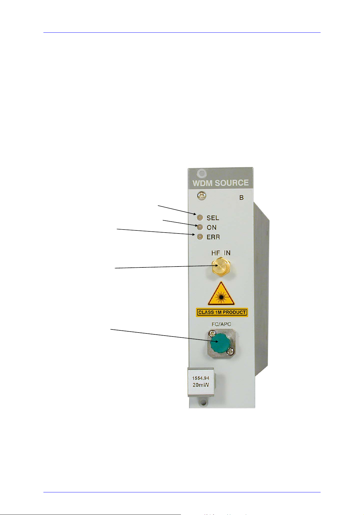
2.1 Operating elements on front panel
LED display "module selected"
LED display "module switched on"
LED display "error"
Modulation input
(BNC or SMA)
Optical output
(FC/APC)
Figure 1 Front view of WDM, CWDM and LS plug-in modules
PRO8000/800 optical sources / page 12

2.2 Connecting external components
2.2 Connecting external components
2.2.1 Connecting an optical fiber
Depending on the construction of the optical connector the fiber is to be connected to
the optical output by means of a corresponding plug.
NOTE
Do not to confuse the FC/PC with the FC/APC connector.
The corresponding type of connector is marked on the module.
Never switch on the output with no fiber connected!
2.2.2 Connecting an external RF modulation source
External modulation is fed to the device by the SMA- or BNC connector in the middle
of the front panel.
Input impedance is 50 Ω.
Attention
To avoid damage to the module do not exceed the following
signal amplitudes: ± 10V DC and RF 1.6 V peak to peak!
For modules with Bias-T see chapter 2.3
2.2.3 Connecting an external DC modulation source
A DC modulation source (DC....10 kHz, TTL) is fed through a BNC connector at the
rear panel of your PRO8000 (-4) / PRO800 mainframe.
Please refer to the mainframe operation manual!
PRO8000 (-4)/800 optical sources / page 13

2.3 Modulating the optical source modules
2.3 Modulating the optical source modules
The state of the art offers different procedures of modulation. Depending on the type
ordered, the following kinds of modulation can be found within the different module
types for analog or digital modulation (WDM, CWDM and LS types).
WDM and CWDM types allow for synchronous modulation (on/off), 0...10 kHz,
internal low frequency modulation (20 ... 50000 Hz, 0.1 ... 100 % rel. Amplitude, and
depending on the type of module additional modulation capabilities.
• Analog direct modulation of internal set parameters
• Analog direct modulation via an internal bias-T
• Analog direct modulation via an internal DC bias-T
• Digital internal DC modulation (synchronous for all modules)
PRO8000/800 optical sources / page 14

2.3 Modulating the optical source modules
2.3.1 Direct modulation via an internal bias-T
The principal set up of a Pro8 optical module with direct modulation via an internal
bias-T
is shown here:
DC Current control
0.1 F
Modulation
µ
Input
50
Ω
Figure 2 Direct modulation via internal bias-T
The (RF) modulation current is superimposed to the DC laser source current by
means of the internal bias-T.
There are no specific parameters to be set.
Input 50 Ω SMA
Signal type Analog AC coupled
Frequency range 100 kHz ... 0.5 GHz
PRO8000 (-4)/800 optical sources / page 15

2.3 Modulating the optical source modules
Attention
You have direct access to the expensive laser diode !
Be sure not to apply any transients
Do not drive the laser diode with more than the rated maximum
current!
NOTES
The modulation current is calculated as:
I
mod
= V
mod
/ 50Ω
Where
I
is the modulation current that is added to the laser diode current
mod
V
is the applied modulation voltage.
mod
In the datasheet supplied with the laser module you will find:
• The relation between I
and the optical output of the laser.
mod
• The allowed maximum laser current.
PRO8000/800 optical sources / page 16

2.3 Modulating the optical source modules
2.3.1.1 Remarks on direct modulation by bias-T
Figure 3 Possible DC-component of digital signals
Laser current with asymmetrical modulation
When modulating via a BIAS-T only the AC component of the modulating signal is
fed to the laser diode. The lower frequency limit of the modulation input is at about
100 ... 500 kHz.
If the modulation signal is asymmetric (e.g. logical high and low levels are not evenly
distributed) this asymmetry corresponds to a DC component. Since this DC
component is not fed to the laser diode, the maximum and minimum value of the
laser current may change.
The figure shows the dependency of the laser current from pulse period ratio with
square modulation.
PRO8000 (-4)/800 optical sources / page 17

2.3 Modulating the optical source modules
2.3.2 Direct modulation via internal DC bias-T
Here the set up of a Pro8 optical module with direct modulation via internal DC bias-T
is shown:
DC Current contro l
Modulation
Input
50
Ω
Figure 4 Direct modulation via internal DC bias-T
The injection current is directly modulated via internal bias-T.
There are no specific parameters to be set.
Attention
You have direct access to the expensive laser diode !
Make sure not to apply any transients!!
Do not drive the laser diode with more than the rated maximum
current!
Input 50 Ω SMA
Signal type Analog DC coupled
Frequency range 0 Hz ... 20 MHz
PRO8000/800 optical sources / page 18

2.3 Modulating the optical source modules
NOTES
The laser is DC-coupled to the input so any input voltage will alter laser
current and laser power. We recommend using an external coupling
capacitor in cases, where no DC-coupling is required.
The modulated laser diode current is calculated as:
I
LDmod
= I
LDCW
+ (V
- VLD) / 50Ω
mod
(Definition of polarities of currents and voltages see next page)
Where
I
is the modulated laser diode current
LDmod
V
is the applied modulation voltage.
mod
I
is the laser diode CW current generated in the module.
LDCW
VLD is the laser diode voltage (laser current dependent, typically
0.8 … 1.8V).
In the datasheet supplied with the laser module you will find:
• The relation between I
and the optical output of the laser.
mod
• The maximum laser current allowed.
• I
at different operating points.
LDCW
PRO8000 (-4)/800 optical sources / page 19

2.3 Modulating the optical source modules
Polarities of currents and voltages:
Cathode Grounded
V - V
mod LD
DC Laser Cur r en t
I
LD CW
50
Ω
I
LD mod
V
LD
Modul ation Input
V
mod
Figure 5 Polarities of currents and voltages with grounded cathode
Anode Grounded
V- V
mod LD
DC Laser Curr en t
I
LD CW
I
LD mod
V
50
LD
Ω
Modulation Input
V
mod
Figure 6 Polarities of currents and voltages with grounded anode
PRO8000/800 optical sources / page 20

2.3 Modulating the optical source modules
FURTHER NOTES
Please do not shortcut the modulation input, as this is an „input voltage“ of
0V influencing the laser diode current (see formula).
The laser diode is operated in constant current mode, so the output power
is dependent on the temperature and thus on the wavelength.
The output power will vary slightly during wavelength tuning.
To avoid any damage to the laser diode the output power will be set to 0 if
the deviation between actual and set wavelength is larger than typ.
0.1 nm. To avoid this in manual operation please turn the knob slowly.
In remote operation do not change the wavelength in steps wider than
0.05 nm and not faster than 0.1nm/s.
PRO8000 (-4)/800 optical sources / page 21

2.3 Modulating the optical source modules
2.3.3 External modulation (PM-output recommended)
If there are still higher requirements regarding the transmission bandwidth at present
only external electro-optical modulators are used. Their inner structure mostly
resembles a Mach-Zehnder interferometer.
Laser Input Laser Output
Modulation Input
Figure 7 External modulation generation
By means of 3 dB couplers the incoming light is divided into two identical beams and
recombined again at the end of the modulator. By applying voltage an electrical field
between the electrodes sets up. The applied electrical field causes changes in the
refractive index in both wave guides (Pockels effect) which are - due to the circuitry reversed to each other. Since the propagation speed of light depends on the
refractive index of the wave guide this results in propagation time differences and
thus in a phase difference. When both beams are recombined, light shares of
opposite phase extinguish each other - the result is an intensity modulation.
Electro-optical modulation excels in a negligible chirping and reaches a high
extinction ratio (modulation depths). The disadvantage of these modulators is their
high attenuation loss (about 4 dB) and the relatively high modulation voltages
required.
Wavelength stability with external modulation
When using external modulators a retroaction on the laser module is excluded as far
as possible if an optical isolator is used. Nevertheless, the consequent use of angle
polished connectors is recommended.
PRO8000/800 optical sources / page 22

2.4 Coherence control
2.4 Coherence control
The PRO8000 (-4) / PRO800 optical source modules (WDM, CWDM) are equipped
with an adjustable coherence control, to reduce unwanted stimulated Brillouin or
Raman Scattering.
Coherence control is done by an internal amplitude modulation with band limited (1-5
kHz) white noise or with a discrete modulation with a sinusoidal, rectangular or
triangular (option) signal in the frequency range 20 Hz … 50 kHz.
A 0% setting in the menu means no noise modulation, a setting of 100% delivers a
maximum of 5% amplitude modulation. This results in a maximum gauss-shaped
line-broadening of typ. more than 1 GHz.
NOTE
Percentage setting and bandwidth are not in strict linear relationship to
each other!
PRO8000 (-4)/800 optical sources / page 23

2.5 Operating the WDM and CWDM modules
2.5 Operating the WDM and CWDM modules
2.5.1 Functions in the main menu
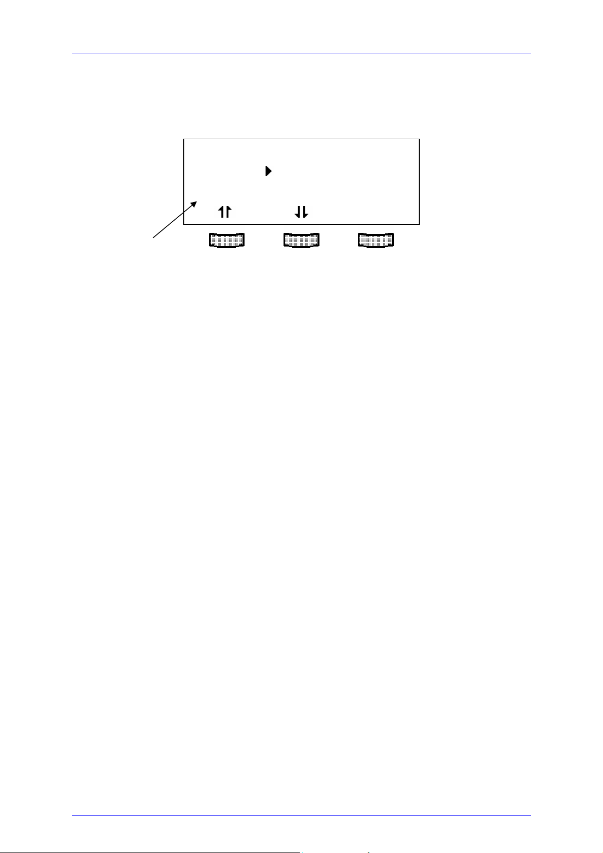
2.5.1.1 Display
The main menu shows the channel number, the wavelength and the status of the
different inserted modules.:
channel no. cursor wavelength state
CH1 1549.31 off
CH2 1533.46 off
CH3 1553.39 off
TUNE
2.5.1.2 Selecting a module
Select a module with the cursor by pressing the softkeys
e.g.:
CH2
and .
The display scrolls up and down.
(The LED “SEL” on the corresponding module front panel will light up).
Press to enter the channel menu
PRO8000/800 optical sources / page 24
2.5 Operating the WDM and CWDM modules
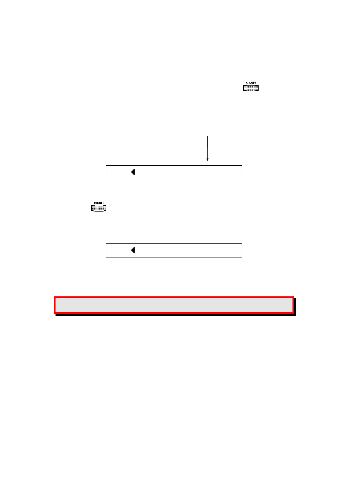
2.5.1.3 Switching modules on and off
Modules can be switched on or off in the main menu or in the channel menu. For this
purpose first select the module (see page 24). Press the key to turn on the
module. The LED “ON” at the respective module will light up and the display shows
the emitted optical power.
Optical power
CH1 1559.31 +3.00dBm
Press the key again to turn off the module. The LED “ON” at the module
extinguishes.
CH1 1559.31 off
Attention
Never switch on the laser output with no fiber installed!
PRO8000 (-4)/800 optical sources / page 25

2.5 Operating the WDM and CWDM modules
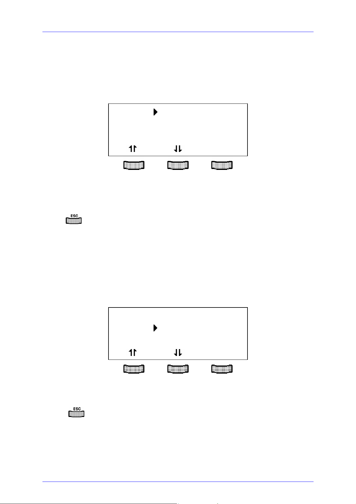
2.5.1.4 Setting of temperature δT and optical power
To set the wavelength or the optical output power in the main menu the corresponding module is selected with the cursor (here: CH1):
CH1 1559.31 +3.00dBm
CH2 -0.12°C off
TUNE
Pressing the key (TUNE) will turn the cursor to the right. Thus indicating the value
to be selected. The softkeys get new functions:
CH1 1559.31 +3.00dBm
CH2 -0.12°C off
TUNE: λ Po
The softkey (λ) selects the wavelength, the softkey (Po) selects the optical power.
The selected value can be adjusted by means of the tuning knob. Press
make new settings valid.
to
PRO8000/800 optical sources / page 26

2.5 Operating the WDM and CWDM modules
2.5.2 Error messages
Error messages are shown in the bottom line of the display regardless of which menu
you are in.
If an error occurs, the display shows for example:
CH1 Po = +0.00dBm
LD on Po =1.0000 mW
CW δT =+0.150 °C
<CH2 OTP > ok
Channel causing the error Error message ok to accept
Possible error messages (depending on the type of module) are:
a) Display messages with interrupt:
<CHn Vcc fail > OK Laser switched off due to an error in the current
sourcing.
<CHn OTP > OK Module is too hot. Operation is possible again after
cooling down
<CHn SHUTTER > OK Shutter is not in the right position or was moved
during operation of the laser diode
<CHn ctrl Temp> OK Operating temperature of the laser not yet reached
PRO8000 (-4)/800 optical sources / page 27

2.5 Operating the WDM and CWDM modules
b) Display messages while changing parameters:
NO PAV TUNE ! OK Attempt to change the set power with modulation
on.
NOT IF MOD ON OK Attempt to change the modulation type while
modulation is on.
AMP TOO HIGH! OK Attempt to switch on modulation when either the
sum of set power and modulation amplitude would
exceed 100% nominal power or the difference between set power and modulation amplitude would
“extinguish” the laser function.
c) Display messages when trying to switch on the module:
CHn OTP ! OK Module is overheated. Wait for cooling down.
CHn Vcc fail OK Power supply error. (Maybe service needed).
CHn ctrl Temp OK Operating temperature of the laser not yet reached.
CHn SHUTTER ! OK Safety shutter (option) not in the right position.
PRO8000/800 optical sources / page 28

2.5 Operating the WDM and CWDM modules
2.5.3 Functions in the channel menu (CW modules)
You can reach the channel menu from the main menu by pressing the key .
Pressing again or
2.5.3.1 Display
In the channel menu all parameters of the selected module will appear:
channel no. cursor wavelength frequency optical power
will lead you back to the main menu.
CH1 λ =1552.524nm
LD on f =193.100THz
CW Po = +3.00dBm
CHANGE
status operating mode
The and keys moves the cursor up and down and let you scroll through the
menu.
PRO8000 (-4)/800 optical sources / page 29

2.5 Operating the WDM and CWDM modules
2.5.3.2 Setting the wavelength
Select the respective line with the cursor:
CH1 λ =1552.524nm
LD on f =193.100THz
CW Po= -3.00dBm
CHANGE
Press (CHANGE) to change the wavelength.
Adjust the wavelength with the tuning knob. The actual wavelength follows your input.
Press
PRO800/PRO8000 (-4) is switched off.
2.5.3.3 Setting the laser frequency
Select the respective line with the cursor:
to finish the wavelength tuning and saves the data even if the
CH1 λ =1552.524nm
LD on f =193.100THz
CW Po= -3.00dBm
CHANGE
Press (CHANGE) to change the laser frequency.
Adjust the frequency with the tuning knob. The actual frequency follows your input.
Press
PRO8000/800 optical sources / page 30
to make settings valid and store the data in a non-volatile memory.

2.5 Operating the WDM and CWDM modules
2.5.3.4 Setting the optical power
You can set the optical power either in dBm or in mW. Both power values are given in
the channel menu. Changing one will also affect the display of the other.
Select the respective line with the cursor:
CH1 f =193.100THz
LD on Po= 6.02dBm
CW Po= 4.000mW
CHANGE
Press (CHANGE) to change the optical power.
Adjust the power with the tuning knob.
Press
2.5.3.5 Read maximum modulation voltage (opt. Bias-T)
If you are using a CW module with the option Bias-T, the maximum allowed RF
modulation voltage ‘V
to make settings valid and store the data in a non-volatile memory.
is displayed in Volt.
‘
max
CH1 Po= 4.000mW
LD off Vmax = 0.316V
SYN+LF SYNCmod = ON
CHANGE
PRO8000 (-4)/800 optical sources / page 31

2.5 Operating the WDM and CWDM modules
2.5.3.6 Switching the modulations on and off
CH1 Po= 4.000mW
LD off SYNCmod = ON
SYN+LF LFmod = ON
CHANGE
Status field
The CW modules can use two type of modulations: external synchronous modulation
and internal low frequency modulation. Both can be applied one by one or together.
The line: 'SYNCmod' allows to switch on or off the synchronous modulation for every
WDM module, which is applied at the BNC jack on the back panel of the PRO8
(0 ... 10 kHz). This modulation is fed synchronously to all WDM modules in the unit
and is a 100% on/off modulation.
The internal low frequency modulation (20Hz ... 50 kHz) is generated separately for
every module.
The status field shows which kinds of modulation are active.
PRO8000/800 optical sources / page 32

2.5 Operating the WDM and CWDM modules
2.5.3.7 Changing waveform and amplitude of LF modulation
You can select between four different modulation waveforms in the line 'LFmod':
sine – square – pulse-- (optional triang) and noise. (The Lfmod must be switched
off, in order to change the modulation type).
In case of sine, square, triangle (optional) and noise you can adjust the relative
modulation depth from 0,1% ... 100% in the line 'LFamp'.
Type of modulation
CH1 LFmod = OFF
LD off LFmod = Sine
CW LFamp = 10%
CHANGE
modulation amplitude
In the case of square modulation, the modulation never extinguishes the laser
function of the diode, whereas the 'Pulse' option is a real on/off modulation.
Therefore the Modulation amplitude cannot be changed here, the amplitude display
shows: 'Pulse'.
2.5.3.8 Change the modulation frequency
CH1 LFamp = 10%
LD off Fmod = 12346Hz
CW CW 1030-003
CHANGE
modulation frequency
Press (CHANGE) to change the modulation frequency.
Adjust the frequency between 20 and 50000 Hz in 1 Hz steps with the tuning knob.
Press
PRO800/PRO8000 (-4) is switched off.
With noise modulation no frequency change is possible. The display only shows
‘noise’.
PRO8000 (-4)/800 optical sources / page 33
to make settings valid and store the data even if the

2.5 Operating the WDM and CWDM modules
2.5.3.9 Display the serial number of the unit
The last line of the menu shows the serial number, here CW module #1030-003.
2.5.4 Functions in the channel menu (modules w i th direct modulation)
You can reach the channel menu from the main menu by pressing the key .
Pressing again or
2.5.4.1 Display
In the channel menu all parameters of the selected module will appear:
channel no. cursor wavelength frequency optical power
will lead you back to the main menu.
CH1 λ =1552.524nm
LD on f =193.100THz
CW Po = +3.00dBm
CHANGE
status operating mode
PRO8000/800 optical sources / page 34

2.5 Operating the WDM and CWDM modules
2.5.4.2 Setting the wavelength
Select the respective line with the cursor:
CH1 λ =1552.524nm
LD on f =193.100THz
CW Po= -3.00dBm
CHANGE
Press (CHANGE) to change the wavelength.
Adjust the wavelength with the tuning knob.
Press
2.5.4.3 Setting the laser frequency
Select the respective line with the cursor:
to make settings valid.
CH1 λ =1552.524nm
LD on f =193.100THz
CW Po= -3.00dBm
CHANGE
Press (CHANGE) to change the laser frequency.
Adjust the frequency with the tuning knob.
Press
PRO8000 (-4)/800 optical sources / page 35
to make settings valid.

2.5 Operating the WDM and CWDM modules
2.5.4.4 Setting the optical power
You can set the optical power either in dBm or in mW. Both power values are given in
the channel menu. Changing one will also affect the display of the other.
Select the respective line with the cursor:
CH1 f =193.100THz
LD on Po= 6.02dBm
CW Po= 4.000mW
CHANGE
Press (CHANGE) to change the optical power.
Adjust the power with the tuning knob.
Press
If you have switched the RF modulation on, the display shows the average power
‘Pav’ instead of the set value ‘P0’
2.5.4.5 Set the lower ECL voltage threshold
You can adapt the lower ECL input threshold voltage of the modulation input to your
set-up by changing the value ‘Vth’. This level is displayed in Volt.
to make settings valid.
CH1 Po= 4.000mW
LD off Vth =-1.300V
SYN+LF HFmod = ON
CHANGE
PRO8000/800 optical sources / page 36

2.5 Operating the WDM and CWDM modules
2.5.4.6 Switching the external RF modulation on and off
CH1 Vth=-1.3000V
LD off HFmod = ON
MOD HF Hfamp= 100%
CHANGE
Status field
Pressing (CHANGE) toggles the status of the external RF modulation between on and
off.
Press
2.5.4.7 Adjusting the external RF modulation amplitude
to store the status, even when power is switched off.
CH1 Vth=-1.3000V
LD off HFmod = ON
SYN+LF Hfamp= 100%
CHANGE
Status field
Pressing (CHANGE) to set the relative external RF modulation amplitude with the
tuning knob.
Press
to store the status, even when power is switched off.
PRO8000 (-4)/800 optical sources / page 37
2.5 Operating the WDM and CWDM modules
2.5.4.8 Switching the modulations on and off
CH1 HFamp = 80%
LD off SYNCmod = ON
SYN+LF LFmod = ON
CHANGE
Status field
The WDM CW modules can use two kinds of modulations: external synchronous
modulation and internal low frequency modulation. Both can be applied one by one or
together. The line: 'SYNCmod' allows to switch on or off the synchronous modulation
for every WDM module, which is applied at the BNC jack on the back panel of the
PRO8 (0 ... 10 kHz). This modulation is fed synchronously to all WDM modules in the
unit and is a 100% on/off modulation.
The internal low frequency modulation (20Hz ... 50 kHz) is generated separately for
every WDM module.
The status field shows which kinds of modulation are active.
PRO8000/800 optical sources / page 38

2.5 Operating the WDM and CWDM modules
2.5.4.9 Changing waveform and amplitude of LF modulation
You can select between four different modulation waveforms in the line 'LFmod':
Sine – Square – Pulse –(triangle, optional) and noise. (The Lfmod must be switched
off, in order to change the modulation type).
In case of sine, square, triangle (optional) and noise you can adjust the relative
modulation depth from 0,1% ... 100% in the line 'LFamp'.
Type of modulation
CH1 LFmod = OFF
LD off LFmod = Sine
CW LFamp = 10%
CHANGE
modulation amplitude
In the case of square modulation, the modulation never extinguishes the laser
function of the diode, whereas the 'Pulse' option is a real on/off modulation.
Therefore the Modulation amplitude cannot be changed here, the amplitude display
shows: 'Pulse'.
2.5.4.10 Change the modulation frequency
CH1 LFamp = 10%
LD off Fmod = 12346Hz
CW DIR 1031-001
CHANGE
modulation frequency
The line 'Fmod' allows you to adjust the modulation frequency between 20 and 50000
Hz in 1 Hz steps. Select the line 'Fmod', press 'change' and adjust the frequency
with the tuning knob. With noise modulation no frequency change is possible. The
display only shows ‘noise’.
2.5.4.11 Display the serial number of the unit
The last line of the menu shows the serial number, here DIR module #1031-001.
PRO8000 (-4)/800 optical sources / page 39

2.5 Operating the WDM and CWDM modules
2.5.5 Functions in the channel menu (WDMias-T-DC or RF)
You can reach the channel menu from the main menu by pressing the key .
Pressing again or
2.5.5.1 Display
In the channel menu all parameters of the selected module will appear:
channel no. cursor wavelength frequency optical power
will lead you back to the main menu.
CH1 λ =1552.524nm
LD on f =193.100THz
CW Po = +3.00dBm
CHANGE
status operating mode
The and keys moves the cursor up and down and let you scroll through the
menu.
PRO8000/800 optical sources / page 40
2.5 Operating the WDM and CWDM modules
2.5.5.2 Setting the wavelength
Select the respective line with the cursor:
CH1 λ =1552.524nm
LD on f =193.100THz
CW Po= -3.00dBm
CHANGE
Press (CHANGE) to change the wavelength.
Adjust the wavelength with the tuning knob. The actual wavelength follows your input.
Press
PRO800/PRO8000 (-4) is switched off.
2.5.5.3 Setting the laser frequency
Select the respective line with the cursor:
to finish the wavelength tuning and saves the data even if the
CH1 λ =1552.524nm
LD on f =193.100THz
CW Po= -3.00dBm
CHANGE
Press (CHANGE) to change the laser frequency.
Adjust the frequency with the tuning knob. The actual frequency follows your input.
Press
PRO800/PRO8000 (-4) is switched off.
PRO8000 (-4)/800 optical sources / page 41
to make settings valid and store the data even if the

2.5 Operating the WDM and CWDM modules
2.5.5.4 Setting the optical power
You can set the optical power either in dBm or in mW. Both power values are given in
the channel menu. Changing one will also affect the display of the other.
Select the respective line with the cursor:
CH1 f =193.100THz
LD on Po= 6.02dBm
CW Po= 4.000mW
CHANGE
Press (CHANGE) to change the optical power.
Adjust the power with the tuning knob.
Press
2.5.5.5 Read maximum modulation voltage (opt. Bias-T)
If you are using a module with the option Bias-T installed, the maximum allowed RF
modulation voltage amplitude ‘V
to make settings valid and store the settings.
is displayed in Volt.
‘
max
CH1 Po= 4.000mW
LD off Vmax = 0.316V
SYN+LF SYNCmod = ON
CHANGE
Attention
Modulation voltages higher than the displayed value may lead to
destruction of the laser diode!
PRO8000/800 optical sources / page 42

2.5 Operating the WDM and CWDM modules
2.5.5.6 Switching the modulations on and off
CH1 Po= 4.000mW
LD off SYNCmod = ON
SYN+LF LFmod = ON
CHANGE
Status field
The WDM modules can use two types of modulations: external synchronous
modulation and internal low frequency modulation. Both can be applied one by one or
together. The line: 'SYNCmod' allows to switch on or off the synchronous modulation
for every optical module, which is applied at the BNC jack on the back panel of the
PRO8 (0 ... 10 kHz). This modulation is fed synchronously to all WDM modules in the
unit and is a 100% on/off modulation.
The internal low frequency modulation (20 Hz ... 50 kHz) is generated separately for
every WDM or CWDM module.
The status field shows which kinds of modulation are active.
PRO8000 (-4)/800 optical sources / page 43

2.5 Operating the WDM and CWDM modules
2.5.5.7 Changing waveform and amplitude of LF modulation
You can select between four different modulation waveforms in the line 'LFmod':
Sine – Square – Pulse –(triangle, optional) and noise. (The Lfmod must be switched
off, in order to change the modulation type).
In case of sine, square, triangle (optional) and noise you can adjust the relative
modulation depth from 0,1% ... 100% in the line 'LFamp'.
Type of modulation
CH1 LFmod = OFF
LD off LFmod = Sine
CW LFamp = 10%
CHANGE
modulation amplitude
In the case of square modulation, the modulation never extinguishes the laser
function of the diode, whereas the 'Pulse' option is a real on/off modulation.
Therefore the Modulation amplitude cannot be changed here, the amplitude display
shows: 'Pulse'.
2.5.5.8 Change the modulation frequency
CH1 LFamp = 10%
LD off Fmod = 12346Hz
CW CCBT 1030-003
CHANGE
modulation frequency
Press (CHANGE) to change the modulation frequency.
Adjust the frequency between 20 and 50000 Hz in 1 Hz steps with the tuning knob.
Press
PRO800/PRO8000 (-4) is switched off.
With noise modulation no frequency change is possible. The display only shows
‘noise’.
PRO8000/800 optical sources / page 44
to make settings valid and store the data even if the

2.5 Operating the WDM and CWDM modules
2.5.5.9 Display the serial number of the unit
The last line of the menu shows the serial number, here CCDM module #1030-003.
with Bias-T option (CCBT).
PRO8000 (-4)/800 optical sources / page 45

2.6 Operating the LS modules
2.6 Operating the LS modules
2.6.1 Functions in the main menu
2.6.1.1 Display
The main menu shows the channel number, the temperature (difference) δT and the
state of the LS module:
channel no. cursor temperature δT state
CH1 +0.00°C off
TUNE
2.6.1.2 Selecting a module
Select a module for further input with the cursor using the softkeys and :
e.g. :CH4
Pressing will lead to the channel menu
(refer to chapter”2.5.1.2”, page 24)
PRO8000/800 optical sources / page 46

2.6 Operating the LS modules
2.6.1.3 Setting of temperature δT and optical power
To set the temperature δT in the main menu the corresponding module is selected
with the cursor (here: CH1):
CH1 +0.01°C +5.00dBm
CH2 -0.12°C off
TUNE
Pressing the key (TUNE) will turn the cursor to the right. Thus indicating the value
to be selected. The softkeys get new functions:
CH1 +0.01°C +5.00dBm
CH2 -0.12°C off
TUNE: δT Po
The softkey (
The selected value can be adjusted by means of the tuning knob. Press
make new settings valid.
δT) selects the temperature, the softkey (Po) selects the optical power.
NOTE
to
With the module switched off only the temperature can be selected. For
presetting the optical power, enter the channel menu, see 2.6.3
PRO8000 (-4)/800 optical sources / page 47

2.6 Operating the LS modules
2.6.1.4 Switching on and off
Modules can be switched on or off in the main menu or in the channel menu. First
select the module (see previous page). Pressing will switch on the module. The
LED “ON” at the respective module will light up and the set optical power is indicated.
Optical power
CH1 +0.02°C +3.00dBm
Pressing the key again will switch off the module. The LED ON at the module
extinguishes.
CH1 +0.02°C off
PRO8000/800 optical sources / page 48

2.6 Operating the LS modules
2.6.2 Error messages
Error messages are shown in the bottom line of the display regardless of which menu
you are in.
If an error occurs, the display shows for example:
CH1 Po = +0.00dBm
LD on Po =1.0000 mW
CW δT =+0.150 °C
<CH2 OTP > ok
Channel causing the error Error message ok to accept
Possible error messages (depending on the type of module) are:
a) Display messages with interrupt:
<CHn Vcc fail > OK Laser switched off due to an error in the current
sourcing.
<CHn OTP > OK Module is too hot. Operation is possible again after
cooling down
<CHn SHUTTER > OK Shutter is not in the right position or was moved
during operation of the laser diode
<CHn ctrl Temp> OK Operating temperature of the laser not yet reached
PRO8000 (-4)/800 optical sources / page 49

2.6 Operating the LS modules
b) Display messages while changing parameters:
NO PAV TUNE ! OK Attempt to change the set power with modulation
on.
NOT IF MOD ON OK Attempt to change the modulation type while
modulation is on.
AMP TOO HIGH! OK Attempt to switch on modulation when either the
sum of set power and modulation amplitude would
exceed 100% nominal power or the difference between set power and modulation amplitude would
“extinguish” the laser function.
c) Display messages when trying to switch on the module:
CHn OTP ! OK Module is overheated. Wait for cooling down.
CHn Vcc fail OK Power supply error. (Maybe service needed).
CHn ctrl Temp OK Operating temperature of the laser not yet reached.
CHn SHUTTER ! OK Safety shutter (option) not in the right position.
PRO8000/800 optical sources / page 50

2.6 Operating the LS modules
2.6.3 Functions in the channel menu (LS)
The channel menu is reached from the main menu by pressing . Pressing
or
2.6.3.1 Display
In the channel menu all parameters of the selected module are shown:
channel no. cursor optical power (dBm and mW) temperature
again will lead you back to the main menu.
CH1 Po = +0.00dBm
LD on Po =1.0000 mW
CW δT =+0.150 °C
ADJUST
status operating mode
PRO8000 (-4)/800 optical sources / page 51

2.6 Operating the LS modules
2.6.3.2 Setting the optical power
To set the optical power (either in dBm or in mW) in the channel menu the respective
line is selected with the cursor:
CH1 Po = +0.00dBm
LD on Po =1.0000 mW
CW δT =+0.150 °C
CHANGE
or:
CH1 Po = +0.00dBm
LD on Po =1.0000 mW
CW δT =+0.150 °C
CHANGE
Pressing the key (CHANGE), will activate the tuning knob to change the optical
power. Pressing
2.6.3.3 Setting the temperature δT
To set the temperature
the cursor:
will terminate the procedure.
δT in the channel menu the respective line is selected with
CH1 Po = +0.00dBm
LD on Po =1.0000 mW
CW δT =+0.150 °C
CHANGE
Pressing the key (CHANGE), will activate the tuning knob enabling the temperature
δT to be changed. Pressing
PRO8000/800 optical sources / page 52
will terminate the procedure.

2.6 Operating the LS modules
2.6.3.4 Switching the synchronous modulation on and off
CH1 δT =+0.150 °C
LD off SYNCmod = ON
SYN LS 1030-003
CHANGE
Status field
The LS modules can use internal synchronous modulation. The line: 'SYNCmod'
allows to switch on or off the synchronous modulation for every WDM or LS module,
which is applied at the BNC jack on the back panel of the PRO8 (0 ... 10 kHz). This
modulation is fed synchronously to all WDM and LS modules in the unit and is a
100% on/off modulation
2.6.3.5 Display the serial number of the unit
The last line of the menu shows the serial number, here LS module #1030-003.
PRO8000 (-4)/800 optical sources / page 53

3.1 General notes on remote control
3 Communication with a control computer
3.1 General notes on remote control
The description of the mainframe of the PRO8000 (-4) / PRO800 includes all
instructions on how to prepare and execute the programming of the system via
computer interface.
The fundamental operation of a PRO8000/800 optical source module is found in this
instruction manual.
(Refer to chapter 2, “Operating the PRO8000 (-4) / PRO800 optical source modules”
page 12
NOTE
All analog values are read and written in SI units, i.e. A (not mA), W (not
mW) etc. Letters may be written in small or capital letters.
PRO8000/800 optical sources / page 54

3.1 General notes on remote control
3.1.1 Nomenclature
Program messages (PC ⇒ PRO8000 (-4)) are written in inverted commas:
"*IDN?"
Response messages (PRO8000 (-4) ⇒ PC) are written in brackets:
[:SLOT 1]
There is a decimal point: 1.234
Parameters are separated with comma: "PLOT 2,0"
Commands are separated with semicolon: "*IDN?;*STB?"
3.1.2 Data format
According to the IEEE 488.2 specifications all data variables are divided into 4
different data formats:
Character response data (<CRD>)
Is a single character or a string. Examples:
A or ABGRS or A125TG or A1.23456A
(Refer to IEE488.2 (8.7.1))
Numeric response data Type 1 (<NR1>)
Is a numerical value with sign in integer notation. Examples:
1 or +1 or -22 or 14356789432
(Refer to IEE488.2 (8.7.2))
PRO8000 (-4)/800 optical sources / page 55

3.1 General notes on remote control
Numeric response data Type 2 (<NR2>)
Is a numerical value with or without sign in floating point notation without exponent.
Examples:
-1.1 or +1.1 or -22.1 or 14356.789432
(Refer to IEE488.2 (8.7.3))
Numeric response data Type 3 (<NR3>)
Is a numerical value with or without sign in floating point notation with exponent with
sign. Examples:
1.1E+1 or +1.1E-1 or -22.1E+1 or 143.56789432E+306
(Refer to IEE488.2 (8.7.4))
PRO8000/800 optical sources / page 56

3.2 Commands of the different light source modules
3.2 Commands of the different light source modules
3.2.1 Select the module slot
":SLOT <NR1>" Selects a slot for further programming
<Nr1>=1…8 (PRO8000), 1…2 (PRO800)
":SLOT?" Queries the selected slot
[:SLOT <NR1><LF>]
NOTE
There are different commands for the different options implemented in the
WDM modules (e.g. EA- or Direct modulation, coherence control etc.)
The commands are listed here in relation to the possible
modulation types!
PRO8000 (-4)/800 optical sources / page 57

3.2 Commands of the different light source modules
3.2.2 WDM Modules with CW mode
3.2.2.1 Programming the coherence control (in %)
(These command are for compatibility with the old WDM modules. The new
commands: see ":LFMOD" and ":LFAMP")
This command has the same function as:
:LFMOD:TYPE NOISE
:LFMOD:ENABLE ON
:LFAMP XX
Programming:
":COHERENCE:SET <NR3>" Program the modulation degree (%) for
coherence control
Reading:
":COHERENCE:SET?" Read the modulation degree (%) for
coherence control
[:COHERENCE:SET <NR3><LF>]
":COHERENCE:MIN?" Read minimum modulation degree (%) for
coherence control
[:COHERENCE:MIN <NR3><LF>]
":COHERENCE:MAX?" Read maximum modulation degree (%) for
coherence control
[:COHERENCE:MAX <NR3><LF>]
PRO8000/800 optical sources / page 58

3.2 Commands of the different light source modules
3.2.2.2 Programming the wavelength (LAMBDA)
Programming:
":LAMBDA:SET <NR3>" Program the wavelength of module (in nm)
Reading:
":LAMBDA:SET?" Read the wavelength of the module
[:LAMBDA:SET <NR3><LF>]
":LAMBDA:MIN?" Read the minimum wavelength allowed
[:LAMBDA:MIN <NR3><LF>]
":LAMBDA:MAX?" Read the maximum wavelength allowed
[:LAMBDA:MAX <NR3><LF>]
3.2.2.3 Turning the laser on and off
Programming:
":LASER ON" Turn the laser output on
":LASER OFF" Turn the laser output off
Reading:
":LASER?" Read status of the laser output
[:LASER ON<LF>]
[:LASER OFF<LF>]
PRO8000 (-4)/800 optical sources / page 59

3.2 Commands of the different light source modules
3.2.2.4 Setting the laser frequency [THz]
Programming:
":LASERFREQ:SET <NR3>" Setting laser frequency in THz
Reading:
":LASERFREQ:SET?" Read the set laser frequency
[:LASERFREQ:SET <NR3><LF>]
":LASERFREQ:MIN?"
Read the minimum allowed frequency
[:LASERFREQ:MIN <NR3><LF>]
":LASERFREQ:MAX?"
Read the maximum allowed frequency
[:LASERFREQ:MAX <NR3><LF>]
3.2.2.5 Selecting the modulation amplitude
Programming:
":LFAMP:SET <NR3>" Select modulation amplitude (%)
Reading:
":LFAMP:SET?" Read selected modulation amplitude (%)
[:LFAMP:SET
3.939536E+000<LF>]
":LFAMP:MIN?" Read minimum modulation amplitude (%)
[:LFAMP:MIN
1.000000E-001<LF>]
":LFAMP:MAX?" Read maximum modulation amplitude (%)
[:LFAMP:MAX
7.000000E+001<LF>]
PRO8000/800 optical sources / page 60

3.2 Commands of the different light source modules
3.2.2.6 Selecting the modulation frequency
Programming:
":LFFREQ:SET<NR3>" Select the modulation frequency [Hz]
Reading:
":LFFREQ:SET?" Read selected modulation frequency
[:LFFREQ:SET
3.939536E+003<LF>]
":LFFREQ:MIN?" Read minimum modulation frequency
[:LFFREQ:MIN
2.000000E+001<LF>]
":LFFREQ:MAX?" Read maximum modulation frequency
[:LFFREQ:MAX
5.000000E+004<LF>]
3.2.2.7 Selecting the modulation type
Programming:
":LFMOD:ENABLE ON" Turn on low frequency modulation
":LFMOD:ENABLE OFF" Turn off low frequency modulation
":LFMOD:TYPE NOISE" Select noise modulation (coherence control)
":LFMOD:TYPE PULSE" Select pulse modulation (on/off)
":LFMOD:TYPE SINE" Select sine wave modulation
":LFMOD:TYPE SQUARE" Select square wave modulation (adj. depth)
":LFMOD:TYPE TRIANGLE" Select triangular modulation
Reading:
":LFMOD:ENABLE?" [:LFMOD:ENABLE ON<LF>]
":LFMOD:TYPE?" [:LFMOD:TYPE SINE<LF>]
PRO8000 (-4)/800 optical sources / page 61

3.2 Commands of the different light source modules
3.2.2.8 Programming the output power in dBm
Programming:
":P_DBM:SET <NR3>" Program the output power of the module (in
dBm)
":P_DBM:START <NR3>" Program the start value (in dBm) for ELCH
":P_DBM:STOP <NR3>" Program the stop value (in dBm) for ELCH
Reading:
":P_DBM:SET?" Read the output power of the module
[:P_DBM:SET <NR3><LF>]
":P_DBM:MIN?" Read the minimum output power allowed
[:P_DBM:MIN <NR3><LF>]
":P_DBM:MAX?" Read the maximum output power allowed
[:P_DBM:MAX <NR3><LF>]
":P_DBM:START?" Read the start value (in dBm) for ELCH
[:P_DBM:START <NR3><LF>]
":P_DBM:STOP?" Read the stop value (in dBm) for ELCH
[:P_DBM:STOP <NR3><LF>]
PRO8000/800 optical sources / page 62

3.2 Commands of the different light source modules
3.2.2.9 Programming the output power in Watt
Programming:
":P_W:SET <NR3>" Program the output power of the module
(in W)
":P_W:START <NR3>" Program the start value (in W) for ELCH
1)
":P_W:STOP <NR3>" Program the stop value (in W) for ELCH
Reading:
":P_W:SET?" Read the set output power of the module
[:P_W:SET <NR3><LF>]
":P_W:MIN?" Read the minimum output power allowed
of the module
[:P_W:MIN <NR3><LF>]
":P_W:MAX?" Read the maximum output power allowed
of the module
[:P_W:MAX <NR3><LF>]
":P_W:START?" Read the start value (in W) for ELCH
[:P_W:START <NR3><LF>]
":P_W:STOP?" Read the stop value (in W) for ELCH
[:P_W:STOP <NR3><LF>]
1
ELCH: Electrical Characterization
PRO8000 (-4)/800 optical sources / page 63

3.2 Commands of the different light source modules
3.2.2.10 Activating the synchronous modulation
Programming:
":SYNCMOD ON" Activate the participation of the module in
synchronous modulation
":SYNCMOD OFF" Deactivate the participation of the module in
synchronous modulation
Reading:
":SYNCMOD?" [:SYNCMOD ON<LF>],
[:SYNCMOD OFF<LF>]
3.2.2.11 Reading the module identification
Reading:
":TYPE:ID?" Read plug-in module ID (here 249)
[:TYPE:ID 249<LF>]
":TYPE:SUB?" Read plug in sub-type (here 2)
[:TYPE:SUB 2<LF>]
":TYPE:TXT?"
Read plug-in module ID as plaintext, e.g.
[:TYPE:TXT WDM81550 CW
20mW<LF>]
":TYPE:SN?"
Read plug-in module serial number, e.g.
[:TYPE:SN 1030-004<LF>]
PRO8000/800 optical sources / page 64

3.2 Commands of the different light source modules
3.2.2.12 Read maximum allowed HF modulation voltage
Reading:
":VHFMAX:ACT?" Read maximum HF modulation voltage in
Volt
[:VHFMAX:ACT
2.000000E-001<LF>]
PRO8000 (-4)/800 optical sources / page 65

3.2 Commands of the different light source modules
3.2.3 CWDM Modules
3.2.3.1 Turning the laser on and off
Programming:
":LASER ON" Turn the laser output on
":LASER OFF" Turn the laser output off
Reading:
":LASER?" Read status of the laser output
[:LASER ON<LF>]
[:LASER OFF<LF>]
3.2.3.2 Querying the laser wavelength [nm]
Reading:
":LAMBDA:SET?" Read the set laser frequency
[:LAMBDA:SET <NR3><LF>]
3.2.3.3 Querying the laser frequency [THz]
Reading:
":LASERFREQ:SET?" Read the set laser frequency
[:LASERFREQ:SET <NR3><LF>]
PRO8000/800 optical sources / page 66

3.2 Commands of the different light source modules
3.2.3.4 Setting the temperature difference δT [K]
Programming:
":DTEMP:SET <NR3>" Set the temperature difference δT
Reading:
":DTEMP:SET?" Read the set temperature difference
[:DTEMP:SET 10.939E+000<LF>]
":DTEMP:MIN?" Read minimum allowed δT
[:DTEMP:MIN
1.000000E-001<LF>]
":DTEMP:MAX?" Read maximum allowed δT
[:DTEMP:MAX 3.0000E+001<LF>]
3.2.3.5 Selecting the modulation amplitude
Programming:
":LFAMP:SET <NR3>" Select modulation amplitude (%)
Reading:
":LFAMP:SET?" Read selected modulation amplitude (%)
[:LFAMP:SET
3.939536E+000<LF>]
":LFAMP:MIN?" Read minimum modulation amplitude (%)
[:LFAMP:MIN
1.000000E-001<LF>]
":LFAMP:MAX?" Read maximum modulation amplitude (%)
[:LFAMP:MAX
7.000000E+001<LF>]
PRO8000 (-4)/800 optical sources / page 67

3.2 Commands of the different light source modules
3.2.3.6 Selecting the modulation frequency
Programming:
":LFFREQ:SET<NR3>" Select the modulation frequency [Hz]
Reading:
":LFFREQ:SET?" Read selected modulation frequency
[:LFFREQ:SET
3.939536E+003<LF>]
":LFFREQ:MIN?" Read minimum modulation frequency
[:LFFREQ:MIN
2.000000E+001<LF>]
":LFFREQ:MAX?" Read maximum modulation frequency
[:LFFREQ:MAX
5.000000E+004<LF>]
3.2.3.7 Selecting the modulation type
Programming:
":LFMOD:ENABLE ON" Turn on low frequency modulation
":LFMOD:ENABLE OFF" Turn off low frequency modulation
":LFMOD:TYPE NOISE" Select noise modulation (coherence control)
":LFMOD:TYPE PULSE" Select pulse modulation (on/off)
":LFMOD:TYPE SINE" Select sine wave modulation
":LFMOD:TYPE SQUARE" Select square wave modulation (adj. depth)
":LFMOD:TYPE TRIANGLE" Select triangular modulation
Reading:
":LFMOD:ENABLE?" [:LFMOD:ENABLE ON<LF>]
":LFMOD:TYPE?" [:LFMOD:TYPE SINE<LF>]
PRO8000/800 optical sources / page 68

3.2 Commands of the different light source modules
3.2.3.8 Programming the output power in dBm
Programming:
":P_DBM:SET <NR3>" Program the output power of the module (in
dBm)
":P_DBM:START <NR3>" Program the start value (in dBm) for ELCH
":P_DBM:STOP <NR3>" Program the stop value (in dBm) for ELCH
Reading:
":P_DBM:SET?" Read the output power of the module
[:P_DBM:SET <NR3><LF>]
":P_DBM:MIN?" Read the minimum output power allowed
[:P_DBM:MIN <NR3><LF>]
":P_DBM:MAX?" Read the maximum output power allowed
[:P_DBM:MAX <NR3><LF>]
":P_DBM:START?" Read the start value (in dBm) for ELCH
[:P_DBM:START <NR3><LF>]
":P_DBM:STOP?" Read the stop value (in dBm) for ELCH
[:P_DBM:STOP <NR3><LF>]
PRO8000 (-4)/800 optical sources / page 69

3.2 Commands of the different light source modules
3.2.3.9 Programming the output power in Watt
Programming:
":P_W:SET <NR3>" Program the output power of the module
(in W)
":P_W:START <NR3>" Program the start value (in W) for ELCH
1)
":P_W:STOP <NR3>" Program the stop value (in W) for ELCH
Reading:
":P_W:SET?" Read the set output power of the module
[:P_W:SET <NR3><LF>]
":P_W:MIN?" Read the minimum output power allowed
of the module
[:P_W:MIN <NR3><LF>]
":P_W:MAX?" Read the maximum output power allowed
of the module
[:P_W:MAX <NR3><LF>]
":P_W:START?" Read the start value (in W) for ELCH
[:P_W:START <NR3><LF>]
":P_W:STOP?" Read the stop value (in W) for ELCH
[:P_W:STOP <NR3><LF>]
1
ELCH: Electrical Characterization
PRO8000/800 optical sources / page 70

3.2 Commands of the different light source modules
3.2.3.10 Activating the synchronous modulation
Programming:
":SYNCMOD ON" Activate the participation of the module in
synchronous modulation
":SYNCMOD OFF" Deactivate the participation of the module in
synchronous modulation
Reading:
":SYNCMOD?" [:SYNCMOD ON<LF>],
[:SYNCMOD OFF<LF>]
3.2.3.11 Reading the module identification
Reading:
":TYPE:ID?" Read plug-in module ID (here 249)
[:TYPE:ID 249<LF>]
":TYPE:SUB?" Read plug in sub-type (here 2)
[:TYPE:SUB 2<LF>]
":TYPE:TXT?"
Read plug-in module ID as plaintext, e.g.
[:TYPE:TXT WDM81550 CW
20mW<LF>]
":TYPE:SN?"
Read plug-in module serial number, e.g.
[:TYPE:SN 1030-004<LF>]
PRO8000 (-4)/800 optical sources / page 71

3.2 Commands of the different light source modules
3.2.4 WDM Modules with direct modulation mode
3.2.4.1 Programming the modulation current I
Programming:
MOD
[%]
":CMOD:SET <NR3>" Program modulation current in %
Reading:
":CMOD:SET?" Read the modulation current
[:CMOD:SET <NR3><LF>]
":CMOD:MIN?" Read the minimum modulation current
[:CMOD:MIN <NR3><LF>]
":CMOD:MAX?" Read the maximum modulation current
[:CMOD:MAX <NR3><LF>]
3.2.4.2 Programming the coherence control
(This command is for compatibility with the old WDM modules. The new commands:
see ":LFMOD" and ":LFAMP")
This command has the same function as:
:LFMOD:TYPE NOISE
:LFMOD:ENABLE ON
:LFAMP XX
Programming:
":COHCNTL ON" Turn on coherence control
":COHCNTL OFF" Turn off coherence control
Reading:
":COHCNTL?" Read status of coherence control (on/off)
[:COHCNTL ON<LF>]
[:COHCNTL OFF<LF>]
PRO8000/800 optical sources / page 72

3.2 Commands of the different light source modules
3.2.4.3 Programming the RF modulation amplitude [%]
Programming:
":HFAMP:SET <NR3>" Program modulation amplitude in %
Reading:
":HFAMP:SET?" Read the modulation amplitude
[:HFAMP:SET <NR3><LF>]
":HFAMP:MIN?" Read the minimum modulation amplitude
[:HFAMP:MIN <NR3><LF>]
":HFAMP:MAX?" Read the maximum modulation amplitude
[:HFAMP:MAX <NR3><LF>]
3.2.4.4 Activating the RF modulation
Programming:
":HFMOD ON" Turn on the RF modulation
":HFMOD OFF" Turn off the RF modulation
Reading:
":HFMOD?" Read status of the RF modulation (on/off)
[:HFMOD ON<LF>]
[:HFMOD OFF<LF>]
PRO8000 (-4)/800 optical sources / page 73

3.2 Commands of the different light source modules
3.2.4.5 Programming the wavelength (LAMBDA)
Programming:
":LAMBDA:SET <NR3>" Set the wavelength of the module (in nm)
Reading:
":LAMBDA:SET?" Read the wavelength of the module
[:LAMBDA:SET <NR3><LF>]
":LAMBDA:MIN?" Read the minimum wavelength allowed
[:LAMBDA:MIN <NR3><LF>]
":LAMBDA:MAX?" Read the maximum wavelength allowed
[:LAMBDA:MAX <NR3><LF>]
3.2.4.6 Switching the output on and off (LASER)
Programming:
":LASER ON" Turning the laser output on
":LASER OFF" Turning the laser output off
Reading:
":LASER?" Read status of the laser output
[:LASER ON<LF>]
[:LASER OFF<LF>]
PRO8000/800 optical sources / page 74

3.2 Commands of the different light source modules
3.2.4.7 Setting the laser frequency (THz)
Programming:
":LASERFREQ:SET <NR3>" Setting laser frequency in THz
Reading:
":LASERFREQ:SET?" Read the set laser frequency
[:LASERFREQ:SET <NR3><LF>]
":LASERFREQ:MIN?"
Read the minimum allowed frequency
[:LASERFREQ:MIN <NR3><LF>]
":LASERFREQ:MAX?"
Read the maximum allowed frequency
[:LASERFREQ:MAX <NR3><LF>]
3.2.4.8 Selecting the modulation amplitude
Programming:
":LFAMP:SET <NR3>" Select modulation amplitude (%)
Reading:
":LFAMP:SET?" Read selected modulation amplitude (%)
[:LFAMP:SET
3.939536E+003<LF>]
":LFAMP:MIN?" Read minimum modulation amplitude (%)
[:LFAMP:MIN
1.000000E-001<LF>]
":LFAMP:MAX?" Read maximum modulation amplitude (%)
[:LFAMP:MAX
7.000000E+001<LF>]
PRO8000 (-4)/800 optical sources / page 75

3.2 Commands of the different light source modules
3.2.4.9 Selecting the modulation frequency
Programming:
":LFFREQ:SET<NR3>" Select modulation frequency
Reading:
":LFFREQ:SET?" Read selected modulation frequency
[:LFFREQ:SET
3.939536E+003<LF>]
":LFFREQ:MIN?" Read minimum modulation frequency
[:LFFREQ:MIN
2.000000E+001<LF>]
":LFFREQ:MAX?" Read maximum modulation frequency
[:LFFREQ:MAX
5.000000E+004<LF>]
3.2.4.10 Selecting the modulation type
Programming:
":LFMOD:ENABLE ON" Turn on low frequency modulation
":LFMOD:ENABLE OFF" Turn off low frequency modulation
":LFMOD:TYPE NOISE" Select noise modulation (coherence control)
":LFMOD:TYPE PULSE" Select pulse modulation (on/off)
":LFMOD:TYPE SINE" Select sine wave modulation
":LFMOD:TYPE SQUARE" Select square wave modulation (adj. depth)
":LFMOD:TYPE TRIANGLE" Select triangular modulation
Reading:
":LFMOD:ENABLE?" [:LFMOD:ENABLE ON<LF>]
":LFMOD:TYPE?" [:LFMOD:TYPE SINE<LF>]
PRO8000/800 optical sources / page 76

3.2 Commands of the different light source modules
3.2.4.11 Programming modulation
Programming:
":MOD ON" Enable modulation
":MOD OFF" Disable modulation
Reading:
":MOD?" Read status of modulation (on / off)
[:MOD ON<LF>]
[:MOD OFF<LF>]
3.2.4.12 Reading the actual average laser power (dBm)
Reading
":PAV_DBM:ACT?" Read the actual average laser power in dBm
[:PAV_DBM:ACT <NR3><LF>]
3.2.4.13 Reading the actual average laser power (W)
Reading
":PAV_W:ACT?" Read the actual average laser power in Watt
[:PAV_W:ACT <NR3><LF>]
PRO8000 (-4)/800 optical sources / page 77

3.2 Commands of the different light source modules
3.2.4.14 Programming the output power in dBm
Programming:
":P_DBM:SET <NR3>" Program the output power (in dBm)
":P_DBM:START <NR3>" Program the start value (in dBm) for ELCH
":P_DBM:STOP <NR3>" Program the stop value (in dBm) for ELCH
Reading:
":P_DBM:SET?" Read the output power of the module
[:P_DBM:SET <NR3><LF>]
":P_DBM:MIN?" Read the minimum output power allowed
[:P_DBM:MIN <NR3><LF>]
":P_DBM:MAX?" Read the maximum output power allowed
[:P_DBM:MAX <NR3><LF>]
":P_DBM:START?" Read the start value (in dBm) for ELCH
[:P_DBM:START <NR3><LF>]
":P_DBM:STOP?" Read the stop value (in dBm) for ELCH
[:P_DBM:STOP <NR3><LF>]
PRO8000/800 optical sources / page 78

3.2 Commands of the different light source modules
3.2.4.15 Programming the output power in Watt
Programming:
":P_W:SET <NR3>" Program the output power (in W)
":P_W:START <NR3>" Program the start value (in W) for ELCH
1
":P_W:STOP <NR3>" Program the stop value (in W) for ELCH
Reading:
":P_W:SET?" Read the set output power of the module
[:P_W:SET <NR3><LF>]
":P_W:MIN?" Read the minimum output power allowed
of the module
[:P_W:MIN <NR3><LF>]
":P_W:MAX?" Read the maximum output power allowed
of the module
[:P_W:MAX <NR3><LF>]
":P_W:START?" Read the start value (in W) for ELCH
[:P_W:START <NR3><LF>]
":P_W:STOP?" Read the stop value (in W) for ELCH
[:P_W:STOP <NR3><LF>]
1
ELCH: Electrical Characterization
PRO8000 (-4)/800 optical sources / page 79

3.2 Commands of the different light source modules
3.2.4.16 Activating the synchronous modulation
Programming:
":SYNCMOD ON" Activate the participation of the module in
synchronous modulation
":SYNCMOD OFF" Deactivate the participation of the module in
synchronous modulation
Reading:
":SYNCMOD?" [:SYNCMOD ON<LF>],
[:SYNCMOD OFF<LF>]
3.2.4.17 Reading the module identification
Reading:
":TYPE:ID?" Read plug-in module ID (should be 243)
[:TYPE:ID 243<LF>]
":TYPE:SUB?" Read plug in sub-type (here 6)
[:TYPE:SUB 6<LF>]
":TYPE:TXT?" Read plug-in module ID in plaintext, e.g.
[:TYPE:TXT WDM81550 DIR
20mW<LF>]
":TYPE:SN?"
Read plug-in module serial number, e.g.
[:TYPE:SN 1030-004<LF>]
PRO8000/800 optical sources / page 80

3.2 Commands of the different light source modules
3.2.4.18 Programming the ECL logical level Uth (V)
Programming:
":VTH:SET <NR3>" Program the ECL logical level (in V)
Reading:
":VTH:SET?" Read the ECL logical level (in V)
[:VTH:SET <NR3><LF>]
":VTH:MIN?" Read the minimum level voltage Uth allowed
[:VTH:MIN <NR3><LF>]
":VTH:MAX?" Read the maximum level voltage Uth allowed
[:VTH:MAX <NR3><LF>]
PRO8000 (-4)/800 optical sources / page 81

3.2 Commands of the different light source modules
3.2.5 WDM Modules with Bias-T
3.2.5.1 Programming the coherence control (in %)
(This command is for compatibility with the old WDM modules. The new commands:
see ":LFMOD" and ":LFAMP")
This command has the same function as:
:LFMOD:TYPE NOISE
:LFMOD:ENABLE ON
:LFAMP XX
Programming:
":COHERENCE:SET: <NR3>" Program the modulation degree (%) for
coherence control
Reading:
":COHERENCE:SET?" Read the modulation degree (%) for
coherence control
[:COHERENCE:SET <NR3><LF>]
":COHERENCE:MIN?" Read minimum modulation degree (%) for
coherence control
[:COHERENCE:MIN <NR3><LF>]
":COHERENCE:MAX?" Read of maximum modulation degree (%) for
coherence control
[:COHERENCE:MAX <NR3><LF>]
PRO8000/800 optical sources / page 82

3.2 Commands of the different light source modules
3.2.5.2 Programming the wavelength (LAMBDA)
Programming:
":LAMBDA:SET <NR3>" Program the wavelength of the module (in m)
Reading:
":LAMBDA:SET?" Read the wavelength of the module
[:LAMBDA:SET <NR3><LF>]
":LAMBDA:MIN?" Read the minimum wavelength allowed
[:LAMBDA:MIN <NR3><LF>]
":LAMBDA:MAX?" Read the maximum wavelength allowed
[:LAMBDA:MAX <NR3><LF>]
3.2.5.3 Switching the output on and off (LASER)
Programming:
":LASER ON" Turn the laser output on
":LASER OFF" Turn the laser output off
Reading:
":LASER?" Read status of the laser output
[:LASER ON<LF>]
[:LASER OFF<LF>]
PRO8000 (-4)/800 optical sources / page 83

3.2 Commands of the different light source modules
3.2.5.4 Setting the laser frequency [THz]
Programming:
Programming:
":LASERFREQ:SET <NR3>" Setting laser frequency in THz
Reading:
":LASERFREQ:SET?" Read the set laser frequency
[:LASERFREQ:SET <NR3><LF>]
":LASERFREQ:MIN?"
Read the minimum allowed frequency
[:LASERFREQ:MIN <NR3><LF>]
":LASERFREQ:MAX?"
Read the maximum allowed frequency
[:LASERFREQ:MAX <NR3><LF>]
3.2.5.5 Selecting the modulation amplitude
Programming:
":LFAMP:SET <NR3>" Select modulation amplitude (%)
Reading:
":LFAMP:SET?" Read selected modulation amplitude (%)
[:LFAMP:SET
3.939536E+000<LF>]
":LFAMP:MIN?" Read minimum modulation amplitude (%)
[:LFAMP:MIN
1.000000E-001<LF>]
":LFAMP:MAX?" Read maximum modulation amplitude (%)
[:LFAMP:MAX
7.000000E+001<LF>]
PRO8000/800 optical sources / page 84

3.2 Commands of the different light source modules
3.2.5.6 Selecting the modulation frequency
Programming:
":LFFREQ:SET<NR3>" Select modulation frequency
Reading:
":LFFREQ:SET?" Read selected modulation frequency
[:LFFREQ:SET
3.539536E+003<LF>]
":LFFREQ:MIN?" Read minimum modulation frequency
[:LFFREQ:MIN
2.000000E+001<LF>]
":LFFREQ:MAX?" Read maximum modulation frequency
[:LFFREQ:MAX
5.000000E+004<LF>]
3.2.5.7 Selecting the modulation type
Programming:
":LFMOD:ENABLE ON" Turn on low frequency modulation
":LFMOD:ENABLE OFF" Turn off low frequency modulation
":LFMOD:TYPE NOISE" Select noise modulation (coherence control)
":LFMOD:TYPE PULSE" Select pulse modulation (on/off)
":LFMOD:TYPE SINE" Select sine wave modulation
":LFMOD:TYPE SQUARE" Select square wave modulation (adj. depth)
":LFMOD:TYPE TRIANGLE" Select triangular modulation
Reading:
":LFMOD:ENABLE?" [:LFMOD:ENABLE ON<LF>]
":LFMOD:TYPE?" [:LFMOD:TYPE SINE<LF>]
PRO8000 (-4)/800 optical sources / page 85

3.2 Commands of the different light source modules
3.2.5.8 Programming the output power in dBm
Programming:
":P_DBM:SET <NR3>" Program the output power (in dBm)
":P_DBM:START <NR3>" Program the start value (in dBm) for ELCH
1
":P_DBM:STOP <NR3>" Program the stop value (in dBm) for ELCH
Reading:
":P_DBM:SET?" Read the set output power of the module
[:P_DBM:SET <NR3><LF>]
":P_DBM:MIN?" Read the minimum output power allowed
of the module
[:P_DBM:MIN <NR3><LF>]
":P_DBM:MAX?" Read the maximum output power allowed
of the module
[:P_DBM:MAX <NR3><LF>]
":P_DBM:START?" Read the start value (in W) for ELCH
[:P_DBM:START <NR3><LF>]
":P_DBM:STOP?" Read the stop value (in W) for ELCH
[:P_DBM:STOP <NR3><LF>]
1
ELCH: Electrical Characterization
PRO8000/800 optical sources / page 86

3.2 Commands of the different light source modules
3.2.5.9 Programming the output power in Watt
Programming:
":P_W:SET <NR3>" Program the output power (in W)
":P_W:START <NR3>" Program the start value (in W) for ELCH
1
":P_W:STOP <NR3>" Program the stop value (in W) for ELCH
Reading:
":P_W:SET?" Read the set output power of the module
[:P_W:SET <NR3><LF>]
":P_W:MIN?" Read the minimum output power allowed
of the module
[:P_W:MIN <NR3><LF>]
":P_W:MAX?" Read the maximum output power allowed
of the module
[:P_W:MAX <NR3><LF>]
":P_W:START?" Read the start value (in W) for ELCH
[:P_W:START <NR3><LF>]
":P_W:STOP?" Read the stop value (in W) for ELCH
[:P_W:STOP <NR3><LF>]
1
ELCH: Electrical Characterization
PRO8000 (-4)/800 optical sources / page 87

3.2 Commands of the different light source modules
3.2.5.10 Activating the synchronous modulation
Programming:
":SYNCMOD ON" Activate the participation of the module in
synchronous modulation
":SYNCMOD OFF" Deactivate the participation of the module in
synchronous modulation
Reading:
":SYNCMOD?" [:SYNCMOD ON<LF>],
[:SYNCMOD OFF<LF>]
3.2.5.11 Reading the module identification
Reading:
":TYPE:ID?" Read plug-in module ID (should be 243)
[:TYPE:ID 243<LF>]
":TYPE:SUB?" Read plug in sub-type (here 4)
[:TYPE:SUB 4<LF>]
":TYPE:TXT?" Read plug-in module ID in text form, e.g.
[:TYPE:TXT WDM81550 CCDM
20mW<LF>]
":TYPE:SN?"
Read plug-in module serial number, e.g.
[:TYPE:SN 1030-004<LF>]
3.2.5.12 Query maximum allowed modulation voltage
Reading:
":VHFMAX:ACT " Read maximum modulation voltage (in V)
PRO8000/800 optical sources / page 88

3.2 Commands of the different light source modules
3.2.6 LS modules
3.2.6.1 Programming the temperature δT
Programming:
":DTEMP:SET <NR3>" Program the temperature deviation δT
Reading:
":DTEMP:SET?" Read the temperature deviation δT
[:DTEMP:SET <NR3><LF>]
":DTEMP:MIN?" Read the minimum allowed temperature
deviation δT
[:DTEMP:MIN <NR3><LF>]
":DTEMP:MAX?" Read the maximum allowed temperature
deviation δT
[:DTEMP:MAX <NR3><LF>]
3.2.6.2 Switching the output on and off (OUTP)
Program:
":LASER ON" Turn the laser output on
":LASER OFF" Turn the laser output off
Reading:
":LASER?" Read status of the laser output
[:LASER ON<LF>]
[:LASER OFF<LF>]
PRO8000 (-4)/800 optical sources / page 89

3.2 Commands of the different light source modules
3.2.6.3 Programming the output power (in dBm)
Programming:
":P_DBM:SET <NR3>" Program the output power (in dBm)
":P_DBM:START <NR3>" Program the start value (in dBm) for ELCH
":P_DBM:STOP <NR3>" Program the stop value (in dBm) for ELCH
Reading:
":P_DBM:SET?" Read the set output power of the module
[:P_DBM:SET <NR3><LF>]
":P_DBM:MIN?" Read the minimum output power allowed
of the module
[:P_DBM:MIN <NR3><LF>]
":P_DBM:MAX?" Read the maximum output power allowed
of the module
[:P_DBM:MAX <NR3><LF>]
":P_DBM:START?" Read the start value (in W) for ELCH
[:P_DBM:START <NR3><LF>]
":P_DBM:STOP?" Read the stop value (in W) for ELCH
[:P_DBM:STOP <NR3><LF>]
PRO8000/800 optical sources / page 90

3.2 Commands of the different light source modules
3.2.6.4 Programming the output power (in W)
Programming:
":P_W:SET <NR3>" Program the output power (in W)
":P_W:START <NR3>" Program the start value (in W) for ELCH
1
":P_W:STOP <NR3>" Program the stop value (in W) for ELCH
Reading:
":P_W:SET?" Read the set output power of the module
[:P_W:SET <NR3><LF>]
":P_W:MIN?" Read the minimum output power allowed
of the module
[:P_W:MIN <NR3><LF>]
":P_W:MAX?" Read the maximum output power allowed
of the module
[:P_W:MAX <NR3><LF>]
":P_W:START?" Read the start value (in W) for ELCH
[:P_W:START <NR3><LF>]
":P_W:STOP?" Read the stop value (in W) for ELCH
[:P_W:STOP <NR3><LF>]
1
ELCH: Electrical Characterization
PRO8000 (-4)/800 optical sources / page 91

3.2 Commands of the different light source modules
3.2.6.5 Activating the synchronous modulation
Programming:
":SYNCMOD ON" Activate the participation of the module in
synchronous modulation
":SYNCMOD OFF" Deactivate the participation of the module in
synchronous modulation
Reading:
":SYNCMOD?" [:SYNCMOD ON<LF>],
[:SYNCMOD OFF<LF>]
3.2.6.6 Reading the module identification
Reading:
":TYPE:ID?" Read plug-in module ID (should be 249)
[:TYPE:ID 249<LF>]
":TYPE:SUB?" Read plug in sub-type (here 7)
[:TYPE:SUB 7<LF>]
":TYPE:TXT?" Read plug-in module ID in plaintext, e.g.
[:TYPE:TXT WDM81300 SLED
2mW <LF>]
":TYPE:SN?"
Read plug-in module serial number, e.g.
[:TYPE:LSLD 1030-004<LF>]
PRO8000/800 optical sources / page 92

3.3 Status reporting
3.3 Status reporting
The WDM8xxxx, C81xxx and LS8xxxx modules provide three 16 bit registers DEC,
DEE and EDE (see Figure 8) and four 8 bit registers ESR, STB, ESE and SRE
(see Figure 9) to program various service request functions and status reporting.
(Please refer to the IEEE488.2-1992 standard chapter 11)
(:STAT:DECn?)
n: Slot number
Figure 8 The 16-Bit Device error registers DEC, DEE and EDE
PRO8000 (-4)/800 optical sources / page 93

3.3 Status reporting
Service
Request
Generation
Output buffer
{
{
{
ERROR Queue
{
{
or serial poll
{
Figure 9 The 8-Bit registers “ESR, STB, ESE and SRE”
PRO8000/800 optical sources / page 94
 Loading...