


Scientific-Grade Digital
Camera User Guide
For Models 8051, 4070, 1501, and 340

Scientific Grade Digital Camera
Table of Contents
Chapter 1 Warning Symbol Definitions ............................................................................................. 1
Chapter 2 Safety................................................................................................................................... 2
2.1. Precautions ................................................................................................................... 2
2.2. Product Care ................................................................................................................. 3
2.2.1. Service .................................................................................................................................. 3
2.2.2. Accessories and Customization ............................................................................................ 3
Chapter 3 Description ......................................................................................................................... 4
3.1. Introduction ................................................................................................................... 4
3.2. Receiving and Unpacking ............................................................................................ 4
3.2.1. Important Information Regarding the Power Supply ............................................................. 4
3.3. Supplied Equipment ..................................................................................................... 5
3.3.1. Optional Items ....................................................................................................................... 5
Chapter 4 Setup & Installation ........................................................................................................... 6
4.1. Pre-Installation .............................................................................................................. 6
4.1.1. Gigabit Ethernet (GigE) System ............................................................................................ 6
4.1.2. Camera Link System ............................................................................................................. 6
4.1.3. USB 3.0 System .................................................................................................................... 6
4.2. Installing the Software.................................................................................................. 7
4.2.1. Load the Distribution Disk ..................................................................................................... 7
4.2.2. Driver Selection ..................................................................................................................... 7
4.2.3. Installing 3rd Party Software Applications ............................................................................ 10
4.3. Connecting the Camera .............................................................................................. 11
4.3.1. Configuring your Gigabit Ethernet adaptor for best performance ....................................... 13
4.3.2. Multiple Camera Operation ................................................................................................. 15
4.4. Optical and Mechanical Mounting Considerations .................................................. 16
4.4.1. Using a C-Mount Lens ........................................................................................................ 16
4.4.2. Mounting the Camera .......................................................................................................... 16
4.4.3. Using the Camera with a Cage System .............................................................................. 17
4.4.4. Compatible Adapters for the Camera ................................................................................. 17
4.5. Optical Front End ........................................................................................................ 18
4.5.1. Description of Components ................................................................................................. 19
4.6. Optical Front End Procedures ................................................................................... 20
4.6.1. Removing the C-mount Lock Ring Assembly ..................................................................... 20
4.6.2. Filter Removal and Replacement Procedure ...................................................................... 21
4.6.3. Re-assembly of the C-mount Lock Ring and Flange Focus Adjustment ............................ 22
4.7. Auxiliary Connector .................................................................................................... 23
4.7.1. Pin Descriptions .................................................................................................................. 23
4.7.2. Signal Descriptions ............................................................................................................. 23
4.7.3. Auxiliary I/O Cable Requirements ....................................................................................... 24
Chapter 5 Operation .......................................................................................................................... 25
5.1. Starting the Camera .................................................................................................... 25
5.2. Camera Timing Diagrams ........................................................................................... 26
Chapter 6 8051M Specifications ...................................................................................................... 28

Scientific Grade Digital Camera
6.1. CCD Specifications ..................................................................................................... 28
6.2. Responsivity ............................................................................................................... 28
6.3. Imaging Specifications ............................................................................................... 28
6.4. Example Frame Rates ................................................................................................ 29
Chapter 7 8051C Specifications ....................................................................................................... 30
7.1. Color CCD Specifications .......................................................................................... 30
7.2. Responsivity ............................................................................................................... 30
7.3. Imaging Specifications ............................................................................................... 30
7.4. Example Frame Rates ................................................................................................ 31
Chapter 8 4070M Specifications ...................................................................................................... 32
8.1. CCD Specifications ..................................................................................................... 32
8.2. Responsivity ............................................................................................................... 32
8.3. Imaging Specifications ............................................................................................... 32
8.4. Example Frame Rates ................................................................................................ 33
Chapter 9 4070C Specifications ....................................................................................................... 34
9.1. Color CCD Specifications .......................................................................................... 34
9.2. Responsivity ............................................................................................................... 34
9.3. Imaging Specifications ............................................................................................... 34
9.4. Example Frame Rates ................................................................................................ 35
Chapter 10 340M Specifications ........................................................................................................ 36
10.1. CCD Specifications ..................................................................................................... 36
10.2. Responsivity ............................................................................................................... 36
10.3. Imaging Specifications ............................................................................................... 37
10.4. Example Frame Rates ................................................................................................ 37
Chapter 11 1501M Specifications ...................................................................................................... 38
11.1. CCD Specifications ..................................................................................................... 38
11.2. Responsivity ............................................................................................................... 38
11.3. Imaging Specifications ............................................................................................... 39
11.4. Example Frame Rates ................................................................................................ 39
Chapter 12 1501C Specifications ....................................................................................................... 40
12.1. Color CCD Specifications .......................................................................................... 40
12.2. Responsivity ............................................................................................................... 40
12.3. Imaging Specifications ............................................................................................... 40
12.4. Example Frame Rates ................................................................................................ 41
Chapter 13 IR Blocking Filter ............................................................................................................. 42

Scientific Grade Digital Camera
Chapter 14 Mechanical Drawings ...................................................................................................... 43
14.1. 8051/4070/1501-GE-TE ................................................................................................ 43
14.2. 8051/4070/1501/340-GE............................................................................................... 43
14.3. 8051/4070/1501-CL-TE ................................................................................................ 44
14.4. 8051/4070/1501/340-CL ............................................................................................... 44
14.5. 8051/4070/1501-USB-TE ............................................................................................. 45
14.6. 8051/4070/1501/340-USB ............................................................................................ 45
14.7. Switching Power Supply ............................................................................................ 46
Chapter 15 Troubleshooting ............................................................................................................... 47
15.1. Interface ...................................................................................................................... 47
15.1.1. GigE Status Indicators ........................................................................................................ 47
15.2. Optical ......................................................................................................................... 48
15.3. Operational .................................................................................................................. 48
15.4. Software ...................................................................................................................... 49
Chapter 16 Maintenance ..................................................................................................................... 50
16.1. Cleaning Guidelines ................................................................................................... 50
16.1.1. Cleaning the Lens of Optical Assembly .............................................................................. 50
16.1.2. Standard (Non-Cooled) Camera Precautions ..................................................................... 50
16.1.3. TE-Cooled Camera Precautions ......................................................................................... 50
16.1.4. Cleaning the Infrared Filter (Standard and TE-Cooled Cameras) ...................................... 51
Chapter 17 Regulatory ........................................................................................................................ 52
17.1. Waste Treatment is Your Own Responsibility .......................................................... 52
17.2. Ecological Background .............................................................................................. 52
17.3. Certifications and Compliance – CE Declaration of Conformity ............................. 53
17.4. FCC Statement ............................................................................................................ 57
17.5. Auxiliary I/O Cable Requirements ............................................................................. 57
Chapter 18 Warranty ............................................................................................................................ 58
18.1. General Product Warranty ......................................................................................... 58
18.2. Specific Warranties .................................................................................................... 58
18.2.1. Optomechanics ................................................................................................................... 58
18.2.2. Optical Tables and Breadboards ........................................................................................ 58
18.2.3. Lasers and Imaging Systems .............................................................................................. 58
18.2.4. Opto-Electronics, Control Electronics, Optics, and Nano-Positioning Product Lines ......... 58
18.2.5. Non-Warranty Repairs ........................................................................................................ 58
18.2.6. Warranty Exclusions ........................................................................................................... 58
Chapter 19 Thorlabs Worldwide Contacts ........................................................................................ 59

Scientific Grade Digital Camera Chapter 1: Warning Symbol Definitions
Symbol
Description
Direct Current
Alternating Current
Both Direct and Alternating Current
Earth Ground Terminal
Protective Conductor Terminal
Frame or Chassis Terminal
Equipotentiality
On (Supply)
Off (Supply)
In Position of a Bi-Stable Push Control
Out Position of a Bi-Stable Push Control
Caution: Risk of Electric Shock
Caution: Hot Surface
Caution: Risk of Danger
Warning: Laser Radiation
Caution: Spinning Blades May Cause Harm
Chapter 1 Warning Symbol Definitions
Below is a list of warning symbols you may encounter in this manual or on your device.
ITN000081-D02 Rev. R 07/23/2018 Page 1

Scientific Grade Digital Camera Chapter 2: Safety
Chapter 2 Safety
2.1. Precautions
Please read the instruction manual carefully before operating your Digital Camera. All statements regarding safety
and technical specifications will only apply when the unit is operated correctly.
Refer to this User’s Guide whenever the following symbols are encountered on the Digital Camera and Power
Supply.
ATTENTION
This symbol indicates that additional information is available in this user guide.
This equipment is intended for laboratory use only and is not certified for medical applications,
including but not limited to, life support situations.
Transportation and delivery may cause the Digital Camera to be warm or cool upon receipt.
Please wait for the device to reach room temperature before attempting to operate.
Mobile telephones, cellular phones, or other radio transmitters are not to be used within the
range of three meters of this unit since the electromagnetic field intensity may exceed the maximum
allowed disturbance values according to EN50082-1.
CAUTION
Check the supply voltage of the system BEFORE plugging in the power supply. Make sure the
included power cord is the correct type for the service you are connecting to AND connected to a
properly grounded power outlet (100 – 240 VAC; 50 – 60 Hz).
There are NO user accessible fuses in this Digital Camera or the included External Power
Supply.
Do not open the Digital Camera or the External Power Supply. Doing so is dangerous and
could result in damage to the unit or death to the user.
WARRANTY WARNING
Do not open the Digital Camera or the external power supply. There are no user serviceable parts in
this product. Opening the device will void your warranty. Any modification or servicing of this
system by unqualified personnel renders Thorlabs free of any liability. This device can only be
returned when packed into the complete original packaging, including all foam packing inserts. If
necessary, ask for replacement packaging. Please contact Thorlabs’ Technical Support at
techsupport@thorlabs.com and a member of our team will be happy to assist you.
ITN000081-D02 Rev. R 07/23/2018 Page 2

Scientific Grade Digital Camera Chapter 2: Safety
2.2. Product Care
Handle the system with care during transportation and unpacking. Banging or dropping the system can damage
the unit or lower system performance. If the system is mishandled during shipment, the optical components may
become misaligned, which could lead to a decrease in the image quality. If this happens, the system will need to
be realigned by qualified personnel. To ensure proper care and operation of your Scientific-Grade Digital Camera,
please follow the handling instructions below.
Do not store or operate in a damp, closed environment.
Do not use solvents on or near the equipment.
Keep away from dust, dirt, and air-borne pollutants (including cigarette smoke). The system is not
designed for outdoor use. Protect the equipment from rain, snow, and humidity.
Do not expose to mechanical or thermal extremes. Protect the equipment from rapid variation in
temperature.
Handle all connectors with care. Do not use unnecessary force as this may damage the connectors.
Clean using a soft, lint free cloth. Use of isopropyl alcohol is permitted, however do not immerse in any
liquid or solvent.
Clean any accessible optical surfaces with an appropriate optics grade tissue or cloth.
2.2.1. Service
Only trained and approved Thorlabs’ personnel should service the system. Please contact Thorlabs’ Technical
Support at techsupport@thorlabs.com and a member of our team will be happy to assist you.
2.2.2. Accessories and Customization
Although the system is easily adapted for custom interfaces, to achieve the listed specifications, this system
should only be used with accessories provided by Thorlabs. Any modification or servicing by unqualified
personnel renders the warranty null and void, leaving Thorlabs free of liability. Please contact Thorlabs for
questions on customization.
ITN000081-D02 Rev. R 07/23/2018 Page 3

Scientific Grade Digital Camera Chapter 3: Description
Chapter 3 Description
3.1. Introduction
Our scientific-grade camera series consists of four monochrome configurations (M) distinguished by their
interface method (Gigabit Ethernet (-GE), Camera Link (-CL), or USB 3.0 (-USB)) and whether or not a
thermoelectric cooler is used (-TE for 8051, 4070, and 1501 only). Color sensors are available in the 8051C,
4070C, and 1501C models as well.
The model format is nnnnM/C-I/O-TE where:
nnnn is the base sensor number, M/C denotes Monochrome vs. Color, I/O denotes the interface, and TE denotes
TE cooling (blank for non-cooled). Ex. 4070C-GE, 8051M-CL-TE …
The cameras are bundled with the full complement of Thorlabs Scientific Imaging (TSI) software. For end-users,
the ThorCam software application provides full control of the camera through an intuitive user interface, and it
allows the user to acquire, pan, zoom, analyze, and save images and metadata.
For developers, TSI also offers a software developer’s kit, which includes a comprehensive API (Application
Programming Interface) to streamline the integration of any TSI camera into your system. After software
installation, the SDK can be found in the Local Disk\Program Files\Thorlabs Imaging\documentation folder. This is
the same for 32 and 64 bit distributions.
This manual is a functional overview of the camera, and it is meant to be a companion to the Camera Quick Start
Guide (ITN000081-D03), ThorCam User Manual (ITN000493-D02), and the TSI Application Programming
Interface Guide (ITN000195-D02). All support documentation is available at www.thorlabs.com as well as in
the Local Disk\Program Files\Thorlabs folder following the installation of ThorCam.
3.2. Receiving and Unpacking
Your camera was thoroughly tested and carefully packed at the factory. Once the camera shipment is accepted
for delivery, the carrier assumes full responsibility for its safe arrival. Should you receive your shipment with any
damage—concealed or apparent—please contact the carrier at once. The carrier will instruct you on how to
initiate a damage claim. If a visual inspection reveals damage upon receipt, it must be noted on the freight bill or
express receipt and the notation signed by the carrier’s agent. Failure to do so can result in the ca rrier refusing to
honor the claim.
To return your camera to TSI for service, you must first contact your local Thorlabs office or distributor and
request a Return Material Authorization (RMA). Returns will not be accepted without an RMA. See Chapter 11,
titled “Warranty Information” for details.
3.2.1. Important Information Regarding the Power Supply
CAUTION
The switching power supply that is provided by TSI for use with this camera operates automatically
over the following range of voltages (100 – 240 VAC; 50 – 60 Hz). Make sure the included power cord
is the correct type for the service you are connecting to AND connected to a properly grounded
power outlet.
Dangerous voltage exists within the power supply. Do not tamper with or open the supply under any
circumstances. Doing so may expose lethal voltage to personnel and will void the warranty.
ITN000081-D02 Rev. R 07/23/2018 Page 4

Scientific Grade Digital Camera Chapter 3: Description
Supplied Equipment
Available Interface Options
Gigabit Ethernet
Includes Intel® Pro/1000 CT PCIe Desktop Adapter and 14'
CAT 5e Cable
Camera Link Interface
Includes VisionLink F4 Camera Link Board
and two 5 m Camera Link cables
USB 3.0 Interface
and one 3 m USB-SS Cable
Accessories
Regulated switch-mode Power Supply with 72”
cord (Supplied line cord appropriate for user’s
country or region)
Spanner Wrench
Lens cap (and IR filter removal tool)
Included Software
Thorlabs Camera Software and SDK
(Available for download from www.thorlabs.com)
GigE Interface Configuration
Camera Link Configuration
USB Configuration
3.3. Supplied Equipment
The following is a list of equipment that may be supplied with your camera, depending on your order
configuration. Figure 1 below shows the different available configurations.
3.3.1. Optional Items
Figure 1 Available Camera Configurations
Auxiliary I/O Patch cable – The auxiliary connector on the camera allows the user to access optional
camera control and internal status signals (see section 4.7).
Order Thorlabs 8050-CAB1 and TSI-IOBOB or TSI-IOBOB2.
ITN000081-D02 Rev. R 07/23/2018 Page 5

Scientific Grade Digital Camera Chapter 4: Setup & Installation
Chapter 4 Setup & Installation
4.1. Pre-Installation
Before proceeding with installation of hardware or software, please identify whether your camera interface is
Camera Link, Gigabit Ethernet (GigE), or USB 3.0.
4.1.1. Gigabit Ethernet (GigE) System
If you purchased a Gigabit Ethernet camera, an Intel PCIe adapter card is provided for use on desktop computer
systems. Although the system will work with other adapters (including laptop GigE adapters), it is recommended
that this card be used for optimal performance on all desktop installations. See
Recommended Installation Sequence
1. Power down the computer.
2. Taking necessary precautions, install the Intel PCIe GigE adapter.
3. Turn on the computer and accept Windows driver recommendations for the newly installed hardware.
4. Run the software installer – follow the steps outlined in the next section, including driver installation.
5. Connect the camera, then apply power and run ThorCam application software.
4.1.2. Camera Link System
Camera Link cameras include an EDT PCIe interface card. Other Camera Link interface cards are not supported.
Recommended Installation Sequence
1. Run the software installer, follow the steps outlined in the next section.
2. Power down the computer.
3. Taking necessary precautions, install the EDT PCIe Camera Link interface card.
4. Turn on the computer.
5. Accept the driver installation recommendations for the newly installed hardware.
6. Connect the camera, then apply power and run ThorCam application software.
4.1.3. USB 3.0 System
If you purchased a USB 3.0 camera, the USB 3.0 “SS” inputs on your PC are supported. USB 2.0 inputs are not
supported at this time. For higher bandwidth applications a number of third-party PCIe USB3.0 cards have been
tested with our camera. Please refer to the Troubleshooting section under Operation for more information.
Recommended Installation Sequence
1. Run the software installer, follow the steps outlined in the next section.
2. Connect the camera, then apply power.
3. Your PC should discover the new USB device and install the necessary Drivers.
4. Run the ThorCam application software.
ITN000081-D02 Rev. R 07/23/2018 Page 6

Scientific Grade Digital Camera Chapter 4: Setup & Installation
4.2. Installing the Software
The Thorlabs camera software runs on Windows 7, 8.1, and 10 operating systems ONLY.
4.2.1. Load the Distribution Disk
A CD or DVD disk can be found with the camera. Load the disk into the CD/DVD drive on the computer you wish
to operate the camera and software.
The installation software will automatically detect whether your system is 32-bit or 64-bit. Loading and detection
could take a minute or two, depending on your drive speed.
4.2.2. Driver Selection
Your camera requires a driver to be installed on your computer. After the welcome screen, acceptance of the
license agreement, and entering your user information, you will be presented with a choice of drivers. Select the
driver that matches the interface on your camera; USB, Gigabit Ethernet, or Camera Link. If you have more than
one camera and with different interfaces, select all that apply. If you’re unsure, select them all.
Select a driver for installation by clicking on the dropdown and selecting either of the two choices; “This feature
will be installed on local hard drive,” or “This feature, and all subfeatures, will be installed on local hard drive.”
There are no subfeatures, so both choices do the same thing.
If you do not wish to install the driver, select “This feature will not be available”
Once a driver is selected, the red X will be replaced with a hard drive icon as shown in the USB selection below.
ITN000081-D02 Rev. R 07/23/2018 Page 7

Scientific Grade Digital Camera Chapter 4: Setup & Installation
Click Next to proceed with the driver installation. Depending on your PC’s configuration and the drivers you
selected, you might encounter the additional Windows security dialogs below. Be sure to click “install” to complete
the operation, otherwise the installer will “roll back” and exit.
Camera Link Driver Installation (if selected). Click “Install”
USB Driver Installation (if selected). Click “Install”
ITN000081-D02 Rev. R 07/23/2018 Page 8

Scientific Grade Digital Camera Chapter 4: Setup & Installation
Gigabit Ethernet Driver Installation (if selected). Click “Install”
Once setup is complete, you may now proceed to the next section that will describe how to connect and power on
your camera. When the camera is connected and powered up, you can navigate to the ThorCam Imaging
Software as shown below
“Start”→”All Programs”→”ThorIabs” →”Scientific Imaging ”→”ThorCam”
Figure 2 Thorlabs Installed Items
ITN000081-D02 Rev. R 07/23/2018 Page 9

Scientific Grade Digital Camera Chapter 4: Setup & Installation
4.2.3. Installing 3rd Party Software Applications
After installation of Thorlabs components is complete, you have access to interfaces for select 3rd-party image
analysis packages you may already have installed on your computer, such as MATLAB™.
3rd-party application interfaces in the following directory:
C:\Program Files\Thorlabs\Scientific Imaging\Scientific Camera Support
Important: Do not develop 3rd-party solutions in this directory, as they will be deleted if you update your
ThorCam software.
To use the MATLAB and LabVIEW interfaces, extract from the Zip file and place in the appropriate directory on
your system.
Special note for users of Micro-manager software: support for Thorlabs scientific cameras is included when you
run versions 1.4.14 and later. If you wish to download or update your Micro-Manager software, please visit
https://micro-manager.org/wiki/Micro-Manager_Open_Source_Microscopy_Software
Before using your camera within Micro-Manager, first make sure that your camera is properly installed and
powered-ON. You may run a session of ThorCam to confirm that the camera, software and drivers are properly
installed. Then, shut down your ThorCam session and start a Micro-manager session.
ITN000081-D02 Rev. R 07/23/2018 Page 10

Scientific Grade Digital Camera Chapter 4: Setup & Installation
4.3. Connecting the Camera
To connect the camera, follow the steps and refer to the diagram below.
1. With the power supply turned off, connect the power supply to the “POWER” connector on the back of the
camera. The connector on the camera is labeled “POWER”.
2. Connect the auxiliary cable (optional, ordered separately) into the port on the camera labeled as “AUX”.
3. Connect the interface cable, either a Gigabit Ethernet (GigE) or a Camera Link, based on your camera
model.
- If you are utilizing a Cat5e Gigabit Ethernet (GigE) Cable: Connect the Ethernet cable to the
port on the camera labeled “GigE”. Connect the other end into the port of the Intel® Gigabit
CT PCI Express desktop adapter, installed in the computer. For a description of the status
LEDs on the camera’s GigE port, please see section 5.1.
Figure 3 Diagram of Connectors on GigE configuration
ITN000081-D02 Rev. R 07/23/2018 Page 11

Scientific Grade Digital Camera Chapter 4: Setup & Installation
- If you are utilizing a Camera Link Cable: Connect one end of the Camera Link cable into the
port labeled “CL 0”. Connect the other end into the port labeled “0” of the EDT VisionLink F4
Camera Link card, installed in the computer. Connect the second Camera Link cable to the
port labeled “CL 1”, and the other end into the port labeled “1” on the Camera Link card. (Port
0 is the default port, while port 1 is used for multi-tap operation.) See Figure 4.
- If you are utilizing a USB 3.0 Cable: Connect one end of the USB 3.0 cable into the camera
port labeled “USB”. Connect the other end into a USB 3.0 “SS” port on your computer. See
Figure 3. For a description of the status LEDs on the USB rear panel, please see
section 5.1.
Figure 4 Diagram of Connectors on CL configuration (Left) and USB 3.0 (Right)
ITN000081-D02 Rev. R 07/23/2018 Page 12

Scientific Grade Digital Camera Chapter 4: Setup & Installation
4.3.1. Configuring your Gigabit Ethernet adaptor for best performance
The Gigabit Ethernet NIC supplied with your camera is essential for the highest data rate performance. Please
use it if at all possible. Ensure that the camera is connected directly to the NIC, not through a switch and shared
with other devices unless necessary, to avoid competition for bandwidth.
Regardless of NIC used, you can configure your NIC for best performance possible by launching the Gigabit
Ethernet Driver installation tool from the Start Menu illustrated in Figure 2. When launched, the following diagram
will appear
Note that USB3 Vision is not installed, even if you have a Thorlabs USB 3.0 camera, as Thorlabs cameras use a
separate USB 3.0 driver. Do not install the USB3 Vision driver.
Click “Advanced…” and select the NIC for your camera from the pulldown in the window shown below. The
Thorlabs NIC is the Intel® Gigabit CT Desktop Adaptor. Depending on your NIC, one or more of the selections
shown will be accessible. Select
eBUS Universal Pro for Ethernet
Jumbo Packet
Maximum value for Receive buffers
Maximum value for Transmit buffer
It should not be necessary to adjust any other parameters.
It is also not necessary to use these settings for your other NICs not associated with the camera (such as the NIC
for your local network).
ITN000081-D02 Rev. R 07/23/2018 Page 13

Scientific Grade Digital Camera Chapter 4: Setup & Installation
ITN000081-D02 Rev. R 07/23/2018 Page 14

Scientific Grade Digital Camera Chapter 4: Setup & Installation
4.3.2. Multiple Camera Operation
If multiple camera operation is required, it is recommended that a Gigabit Ethernet switch topology be setup, as
shown below. When multiple cameras are connected and powered on, they will be visible in the Image Detector
dropdown of Hardware Setup panel. Both control and display revert to the camera that is selected from the
dropdown menu.
Figure 5 Gigabit Ethernet Switch Topology Setup for Multiple Cameras
ITN000081-D02 Rev. R 07/23/2018 Page 15

Scientific Grade Digital Camera Chapter 4: Setup & Installation
4.4. Optical and Mechanical Mounting Considerations
4.4.1. Using a C-Mount Lens
For the best results, the use of a C-Mount lens that matches the optical format of the 4/3” (22mm) imaging area is
recommended. For more information on Thorlabs C-Mount lenses, please visit www.thorlabs.com
C-mount lenses are specified with a flange focal distance of 17.5 mm. However, there can be considerable
variation in the flange focal distance among commercially available lenses.
To accommodate the variation in commercially available lenses, the camera has an adjustable flange focal range
of ± 1.5 mm. A procedure to set the flange focal distance is described in the next section.
Figure 6 Camera Shown with C-Mount Lens (not supplied) Using the C-Mount Adapter
4.4.2. Mounting the Camera
On most commercial microscopes, the use of a suitable adapter is recommended in order to match the optical
format of the 4/3” (22mm) imaging area. Please note that some commercial 1x adapters may underfill the imaging
area, leading to vignetting of the image.
The adjustable flange focus may also be used to parfocalize a microscope, as described in the next section.
Figure 7 Camera Shown on Microscope Using C-Mount Adapter
ITN000081-D02 Rev. R 07/23/2018 Page 16

Scientific Grade Digital Camera Chapter 4: Setup & Installation
Four 1/4”-20 tapped holes are provided, one on each side of the housing. These may be used with tripods, or
other optical mounting devices. These 1/4”-20 tapped holes are compatible with Thorlabs 1/2” posts. For more
information on Thorlabs Ø1/2" posts, please visit www.thorlabs.com.
Figure 8 Arrows Indicate Two of the Four 1/4”-20 Tapped Holes on Camera
4.4.3. Using the Camera with a Cage System
The cameras have 4-40 tapped holes for compatibility with Thorlabs 60 mm Cage system.
For more information on Thorlabs 60 mm Cage system components, please visit www.thorlabs.com.
Figure 9 Camera Shown as Part of a 60 mm Thorlabs Cage System
4.4.4. Compatible Adapters for the Camera
The cameras standard C-mount (1.000"-32) threading may be adapted with thread-to-thread adapters. For
example, Thorlabs SM1A9 or SM1A9TS adapter with external c-mount threads and internal SM1 1.035"-40
threading may be used with Thorlabs 1" lens tubes.
Figure 10 Thorlabs SM1A9 Adapter with External C-Mount Threads and Internal SM1 Threads
ITN000081-D02 Rev. R 07/23/2018 Page 17

Scientific Grade Digital Camera Chapter 4: Setup & Installation
IR Blocking
Filter
Filter Retaining
Ring
Lens Cap
(and Filter Removal Tool)
C-Mount Adapter
and Lock Nut
4.5. Optical Front End
The images below show the components located on the front end of the camera.
Figure 11 Exploded View of Optical and Mechanical Components
Figure 12 Optical and Mechanical Sub-Assemblies
Figure 13 Reverse View Showing IR Filter and Associated Components
ITN000081-D02 Rev. R 07/23/2018 Page 18

Scientific Grade Digital Camera Chapter 4: Setup & Installation
Figure 14 Reverse View of IR Filter Sub-Assembly. Shows the Lens Cap Used as a Tool for
Installing and Removing the Filters
4.5.1. Description of Components
C-Mount Adapter: Allows the camera to be optically coupled with standard C-mount optics, including
lenses and microscope adapters.
Lock Nut: Used to secure the c-mount adapter to the main camera body, while allowing adjustability of
the back focus distance. A wrench is provided to loosen and tighten the lock nut (See Section 4.6)
Lens Cap: A protective cover that should be installed during shipment and also when the camera is not in
use.
Note Dual use of lens cap as a tool for removing/installing the filter retaining ring) - the lens cap has two
metallic prongs/inserts which allows it to also be reversed and used as a tool for removing or installing the
filter retaining ring. The metal prongs are sized to fit into the two holes in the filter retaining ring, which
can then be screwed into the back of the c-mount adapter ring. A groove in the back of the c-mount
adapter ring accommodates the IR-block as an insert.
IR Blocking Filter: Unless otherwise requested, an IR filter is typically installed and held in place by a
filter retaining ring. Silicon CCD imagers have responsivity that extends beyond the VIS range, into the
NIR spectral range. The IR filter is intended to cut off at higher wavelengths. Users may, at their
discretion, remove the IR filter in NIR imaging applications - or replace it with a custom optical filter with
the same nominal dimensions. Note: maximum filter thickness = 0.050” (1.270 mm). See Chapter 13 for
more information
ITN000081-D02 Rev. R 07/23/2018 Page 19

Scientific Grade Digital Camera Chapter 4: Setup & Installation
4.6. Optical Front End Procedures
4.6.1. Removing the C-mount Lock Ring Assembly
Removal of the C-mount lock lens ring is not required for normal operation. It is required if users wish to remove,
replace, or clean the installed filter. Follow the steps below to remove the C-mount ring assembly.
Note: Re-adjustment of the lens back-focus will be required after re-assembly. See the “Back Focus Adjustment”
in Section 4.6.3.
1. Loosen the lens mount lock ring with the supplied wrench.
Figure 15 Loosening the C-mount and IR-Block Filter Assembly from Camera
2. Unscrew the C-mount lock ring assembly from the camera body and remove the lock ring from the Cmount adapter.
Figure 16 Removing the C-mount and IR-Block Filter Assembly from Camera Body
ITN000081-D02 Rev. R 07/23/2018 Page 20

Scientific Grade Digital Camera Chapter 4: Setup & Installation
4.6.2. Filter Removal and Replacement Procedure
TSI cameras are typically provided with an IR-blocking filter installed. The CCD has responsivity into the Near
Infrared (for more details refer to specifications sections near the end of this document).
If near-infrared sensitivity is desired, the IR-blocking filter should not be installed.
The optical front end is designed to accommodate standard 1” filters. Users may, at their discretion, operate the
camera without any glass installed or install custom filters in front of the CCD.
Note: If no glass is installed, dust and debris may collect on the CCD faceplate. Please use every precaution to
avoid contact with the CCD faceplate and to keep the camera securely mounted to the optical system or capped
when not in use.
Removal of the Filter from the C-mount Adapter
1. Hold the lens cap with the pins sticking upward in one hand.
2. Lower the C-mount adapter on to the pins with the other hand.
3. Hold the lens cap and rotate the C-mount adapter counter-clockwise and then remove the lens ring.
4. Remove the filter from the filter ring with lens tissue and store in a protective container.
5. Replace the lens ring on to the C-mount adapter and screw on clockwise.
6. Remove the lens cap.
7. To re-install the filter, reverse the above procedure.
8. Screw the C-mount adapter back into the locking ring and screw both back onto the camera.
Figure 17 Removal of the IR-Blocking Filter from the Assembly
ITN000081-D02 Rev. R 07/23/2018 Page 21

Scientific Grade Digital Camera Chapter 4: Setup & Installation
4.6.3. Re-assembly of the C-mount Lock Ring and Flange Focus Adjustment
1. Install C-mount ring adapter into the front side of the camera as shown in Figure 18.
Do NOT tighten or lock.
2. Install a C-Mount lens (not provided) onto the camera.
3. Ensure that the lens is screwed all the way into the C-mount adapter but with the tapered lock-nut ring
loosened so that the lens and the adaptor can be adjusted together.
4. Power up the camera and launch ThorCam software.
5. Set gain, black level and exposure to settings that result in a live image.
6. Set Camera Lens Focus to ∞ infinity.
7. Adjust Camera Lens Iris to obtain a viewable image.
8. Point the camera to an object far away which is at infinity.
9. Adjust C-mount lens ring on the camera until image is at best focus.
10. When image is in sharp focus, lens “Back Focus” is properly set.
11. Tighten the Tapered Lock Ring using the Focusing wrench to secure setting
Figure 18 Re-assembly of the C-Mount Assembly onto Camera
Note: To obtain parfocality on a microscope installation, ensure that the camera port of the microscope is
screwed into the lens adapter but with the tapered lock ring loosened. Move the assembly until the camera image
and the images viewed through the oculars are simultaneously in focus. Tighten the Tapered Lock Ring using the
focusing wrench to secure the setting.
ITN000081-D02 Rev. R 07/23/2018 Page 22

Scientific Grade Digital Camera Chapter 4: Setup & Installation
Pin Descriptions
Pin #
Signal
1
Reserved
2
Reserved
3
Reserved
4
STROBE_OUT
5
TRIGGER_IN
6
LVAL_OUT
7
TRIGGER_OUT
8
LVDS_TRIGGER_IN-N
(Differential Pair with Pin 9)
9
LVDS_TRIGGER_IN-P
(Differential Pair with Pin 8)
10
Ground
11
Reserved
12
FVAL_OUT
4.7. Auxiliary Connector
The auxiliary connector on the camera allows the user to access optional camera control and internal status
signals.
4.7.1. Pin Descriptions
Figure 19 Illustration of the Auxiliary Connector on the
Rear of the Camera
4.7.2. Signal Descriptions
Pins 1, 2, 3, 11: Reserved.
Pin 4, STROBE_OUT (Output): STROBE_OUT is a TTL output that is high during the actual sensor
exposure time when in continuous, overlapped exposure mode. STROBE_OUT is typically used to
synchronize an external flash lamp or other device with the camera.
Pin 5 TRIGGER_IN (Input): TRIGGER_IN is a TTL input used to trigger exposures on the transition from
the HIGH state to LOW state.
Pin 6, LVAL_OUT (Output): LVAL_OUT refers to “Line Valid Output.” It is an active-HIGH TTL signal
and is asserted during the valid pixel period on each line. It returns low during the inter-line period
between each line and during the inter-frame period between each frame.
Pin 7, TRIGGER_OUT (Output): TRIGGER_OUT is a 6μs positive pulse that is asserted when using the
various external trigger input options; TRIGGER_IN, LVDS_TRIGGER_IN, or the Camera Link CC1
signal. The CC1 signal, driven from the host, is one of the software-controlled trigger signals for the
camera. The CC1 signal is brought out of the camera as TRIGGER_OUT at the High-to-Low transition to
allow triggering of other devices. The same applies to the other external triggers.
Pins 8, 9 LVDS_TRIGGER_IN_N and LVDS_TRIGGER_IN_P (Input): LVDS_TRIGGER_IN is an LVDS
(low voltage differential signal) input used to trigger exposures on the transition from the HIGH state to
LOW state. Suffixes “N” and “”P identify the negative and positive inputs respectively of the LVDS signal.
Pin 10, GND: This is the electrical ground for the camera signals.
Pin 12, FVAL_OUT (Output): FVAL_OUT refers to “Frame Valid Output” and is a TTL output that is
HIGH during active readout lines. FVAL_OUT remains high throughout the active readout and returns low
between frames.
ITN000081-D02 Rev. R 07/23/2018 Page 23

Scientific Grade Digital Camera Chapter 4: Setup & Installation
4.7.3. Auxiliary I/O Cable Requirements
An auxiliary I/O cable may be fabricated in order to connect to the AUX I/O port of the camera. This cable is
application specific in all cases due to varying lengths and functions that are used. If an Auxiliary I/O cable is to
be used with this camera it must be constructed using shielded cabling in order for the camera to adhere to CE
and FCC compliance. The mating connector for the rear panel connector is HIROSE HR10-10P-12P (73).
A 10 foot long (3m) auxiliary I/O cable and interconnect break-out board are available from Thorlabs allowing
access to some of the I/O control functions (Trigger_In, Trigger_Out, LVAL_Out, FVAL_Out, and Strobe_Out).
Order the “8050-CAB1” and the “TSI-IOBOB”, as well as the required number and style of SMA patch cables for
your specific application. Order the CA28xx SMA-to-BNC series (i.e. CA2848 for 48” cable) or the CA29xx SMAto-SMA series (CA2948 for 48” cable) as needed.
ITN000081-D02 Rev. R 07/23/2018 Page 24

Scientific Grade Digital Camera Chapter 5: Operation
LED
Color
If LED is Flashing
If LED is On
If LED is Off
Green
The Link is Operational, but
the Camera is Currently not
Sending Data
Normal (Indicates
that the Camera is
Sending Data)
There is no Ethernet
Connection
Amber
Normal Operation
Not Applicable
Either there is no Ethernet
Connection, or The
Camera is Plugged into a
10/100 Mbps Network
LED
If LED is Flashing
If LED is On
If LED is Off
Link
Not Applicable
Blue: Connected to
a USB 3.0 Port
Green: Connected
to a USB 2.0 Port
Amber: Camera has
internal USB
problem
There is no USB
Connection or,
Camera is powered off
Status
Green: Camera is sending
frames
Green: Camera is
paused
Camera is powered off
Chapter 5 Operation
The 8051/4070/1501/340-series cameras can be operated using the ThorCam and ThorImageLS (Offered
separately by Thorlabs Imaging Systems). For more details on using ThorCam and ThorImageLS features, please
consult the ThorCam and ThorImageLS User Manuals.
5.1. Starting the Camera
With the camera software installed and the camera connected as instructed, turn on the camera power supply. A
green indicator on the supply indicates it is operating.
In the case of Gigabit Ethernet cameras, both the Yellow and Green indicators should light up on the camera’s
Gigabit Ethernet connector several seconds after power is applied. It is normal for the Yellow indicator to stay on
continuously, and for the Green indicator to flash when the camera is sending data. The table below details the
conditions represented by the status indicators.
In the case of USB 3.0 cameras, the Status LED should light up solid Green several seconds after power is
applied, and start flashing whenever the camera is generating frames. The Link LED will briefly be solid white
when powering up the camera, and is active whenever the camera is connected to, and enumerated by a USB
port. The table below details the conditions represented by the status indicators.
ITN000081-D02 Rev. R 07/23/2018 Page 25
Scientific Grade Digital Camera Chapter 5: Operation
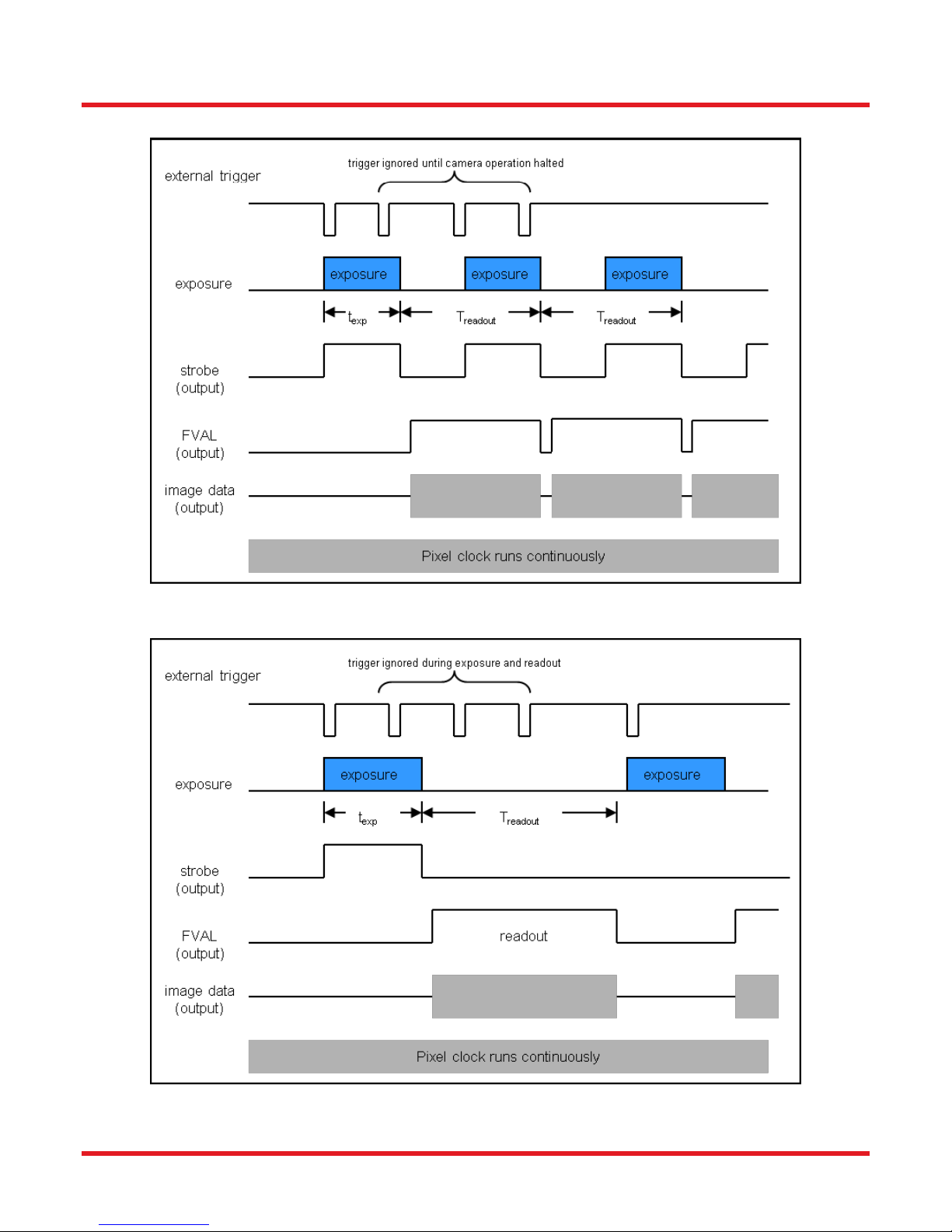
5.2. Camera Timing Diagrams
Figure 20 Timing Diagram – Standard, Frames per Trigger = 0 or > 1
Figure 21 Timing Diagram – Standard, Frames per Trigger = 1
ITN000081-D02 Rev. R 07/23/2018 Page 26

Scientific Grade Digital Camera Chapter 5: Operation
Figure 22 Timing Diagram – Bulb Mode
ITN000081-D02 Rev. R 07/23/2018 Page 27

Scientific Grade Digital Camera Chapter 6: 8051M Specifications
CCD Specifications
CCD Manufacturer and Item Number
On Semi KAI-08051-AXA-JD-BA
Number of Active Pixels
3296 (H) x 2472 (V)
Pixel Size
5.5 m X 5.5 m
Optical Format
4/3” Format (22mm diagonal)
Imaging Specifications
Exposure Time
0 to 1000 seconds in 1 ms increments*
CCD Pixel Clock Speed
20 MHz or 40 MHz
ADC Resolution
-GE 14 bits (1-Tap) / 12 bits (2-Tap)
-CL 14 bits (1-Tap, 2-Tap, 4-Tap)
-USB 14 bits (1-Tap, 2-Tap, 4-Tap)
ADC Gain
0 to 1023 counts
Optical Black Clamp
0 to 1023 counts
Vertical Hardware Binning
1 to 10
Region of Interest
1 x 1 pixel to 3296 x 2472 pixels,
rectangular
Read Noise
< 10 e- @ 20 MHz
Chapter 6 8051M Specifications
6.1. CCD Specifications
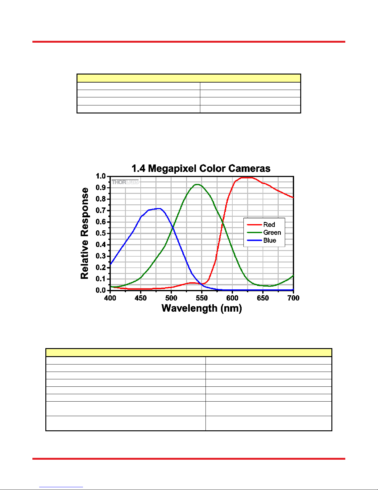
6.2. Responsivity
An IR-blocking filter is typically installed. This filter may be removed if NIR responsivity is desired. See Chapter 13
for specifications related to the IR-blocking filter.
6.3. Imaging Specifications
*Exposure time increment varies with operating mode.
ITN000081-D02 Rev. R 07/23/2018 Page 28

Scientific Grade Digital Camera Chapter 6: 8051M Specifications
Example Frame
Rates @
1 ms Exposure Time
One Tap
Two Tap
Four Tap
20 MHz
40 MHz
20
MHz
40
MHz
20
MHz
40
MHz
Full Sensor (3296 x 2472)
2.3 fps
4.5 fps
4.4 fps
8.5 fps
8.8 fps
17.1 fps
Full Sensor, Bin by 2
(1648 x 1236)
4.4 fps
8.5 fps
8.3 fps
15.7 fps
16.6 fps
31.2 fps
Full Sensor, Bin by 10
(329 x 247)
17.0 fps
29.9 fps
29.0 fps
47.1 fps
56.8 fps
92.3 fps
6.4. Example Frame Rates
ITN000081-D02 Rev. R 07/23/2018 Page 29

Scientific Grade Digital Camera Chapter 7: 8051C Specifications
CCD Specifications
CCD Manufacturer and Item Number
On Semi KAI-08051-FXA-JD-BA
Number of Active Pixels
3296 (H) x 2472 (V)
Pixel Size
5.5 m X 5.5 m
Optical Format
4/3” Format (22mm diagonal)
Imaging Specifications
Exposure Time
0 to 1000 seconds in 1 ms increments*
CCD Pixel Clock Speed
20 MHz or 40 MHz
ADC Resolution
-GE 14 bits (1-Tap) / 12 bits (2-Tap)
-CL 14 bits (1-Tap, 2-Tap, 4-Tap)
-USB 14 bits (1-Tap, 2-Tap, 4-Tap)
ADC Gain
0 to 1023 counts
Optical Black Clamp
0 to 1023 counts
Vertical Hardware Binning
1 to 10
Region of Interest
1 x 1 pixel to 3296 x 2472 pixels,
rectangular
Read Noise
< 10 e- at 20 MHz
Chapter 7 8051C Specifications
7.1. Color CCD Specifications
7.2. Responsivity
An IR-blocking filter is typically installed. This filter may be removed if NIR responsivity is desired. See Chapter 13
for specifications related to the IR-blocking filter.
7.3. Imaging Specifications
*Exposure time increment varies with operating mode.
ITN000081-D02 Rev. R 07/23/2018 Page 30

Scientific Grade Digital Camera Chapter 7: 8051C Specifications
Example Frame
Rates @
1 ms Exposure Time
One Tap
Two Tap
Four Tap
20 MHz
40 MHz
20
MHz
40
MHz
20
MHz
40
MHz
Full Sensor (3296 x 2472)
2.3 fps
4.5 fps
4.4 fps
8.5 fps
8.8 fps
17.1 fps
Full Sensor, Bin by 2
(1648 x 1236)
4.4 fps
8.5 fps
8.3 fps
15.7 fps
16.6 fps
31.2 fps
Full Sensor, Bin by 10
(329 x 247)
17.0 fps
29.9 fps
29.0 fps
47.1 fps
56.8 fps
92.3 fps
7.4. Example Frame Rates
ITN000081-D02 Rev. R 07/23/2018 Page 31

Scientific Grade Digital Camera Chapter 8: 4070M Specifications
CCD Specifications
CCD Manufacturer and Item Number
On Semi KAI-04070M
Number of Active Pixels
2048 (H) x 2048 (V)
Pixel Size
7.4 m X 7.4 m
Optical Format
4/3” Format (21.4mm diagonal)
Imaging Specifications
Exposure Time
0 to 1000 seconds in 1 ms increments*
CCD Pixel Clock Speed
20 MHz or 40 MHz
ADC Resolution
-GE 14 bits (1-Tap) / 12 bits (2-Tap)
-CL 14 bits (1-Tap, 2-Tap, 4-Tap)
-USB 14 bits (1-Tap, 2-Tap, 4-Tap)
ADC Gain
0 to 1023 counts
Optical Black Clamp
0 to 1023 counts
Vertical Hardware Binning
1 to 10
Region of Interest
1 x 1 pixel to 2048 x 2048 pixels,
rectangular
Read Noise
< 12 e- at 20 MHz
Chapter 8 4070M Specifications
8.1. CCD Specifications
8.2. Responsivity
An IR-blocking filter is typically installed. This filter may be removed if NIR responsivity is desired. See Chapter 13
for specifications related to the IR-blocking filter.
8.3. Imaging Specifications
*Exposure time increment varies with operating mode.
ITN000081-D02 Rev. R 07/23/2018 Page 32

Scientific Grade Digital Camera Chapter 8: 4070M Specifications
Example Frame Rates
@
1 ms Exposure Time
One Tap
Two Tap
Four Tap
20 MHz
40 MHz
20 MHz
40 MHz
20 MHz
40 MHz
Full Sensor (2048 x 2048)
4.1 fps
7.7 fps
7.4 fps
13 fps
14.8 fps
25.8 fps
Full Sensor, Bin by 2
(1024 x 1024)
7.5 fps
13.1 fps
12.8 fps
20.5 fps
25.3 fps
40.6 fps
Full Sensor, Bin by 10
(204 x 204)
21.6 fps
30.5 fps
30.0 fps
38.1 fps
58.8 fps
75.1 fps
8.4. Example Frame Rates
ITN000081-D02 Rev. R 07/23/2018 Page 33

Scientific Grade Digital Camera Chapter 9: 4070C Specifications
CCD Specifications
CCD Manufacturer and Item Number
On Semi KAI-04070-FBA
Number of Active Pixels
2048 (H) x 2048 (V)
Pixel Size
7.4 m X 7.4 m
Optical Format
4/3” Format (21.4mm diagonal)
Imaging Specifications
Exposure Time
0 to 1000 seconds in 1 ms increments*
CCD Pixel Clock Speed
20 MHz or 40 MHz
ADC Resolution
-GE 14 bits (1-Tap) / 12 bits (2-Tap)
-CL 14 bits (1-Tap, 2-Tap, 4-Tap)
-USB 14 bits (1-Tap, 2-Tap, 4-Tap)
ADC Gain
0 to 1023 counts
Optical Black Clamp
0 to 1023 counts
Vertical Hardware Binning
1 to 10
Region of Interest
1 x 1 pixel to 2048 x 2048 pixels,
rectangular
Read Noise
< 12 e- at 20 MHz
Chapter 9 4070C Specifications
9.1. Color CCD Specifications
9.2. Responsivity
An IR-blocking filter is typically installed. This filter may be removed if NIR responsivity is desired. See Chapter 13
for specifications related to the IR-blocking filter.
9.3. Imaging Specifications
*Exposure time increment varies with operating mode.
ITN000081-D02 Rev. R 07/23/2018 Page 34

Scientific Grade Digital Camera Chapter 9: 4070C Specifications
Example Frame Rates
@
1 ms Exposure Time
One Tap
Two Tap
Four Tap
20 MHz
40 MHz
20 MHz
40 MHz
20 MHz
40 MHz
Full Sensor (2048 x 2048)
4.1 fps
7.7 fps
7.4 fps
13 fps
14.8 fps
25.8 fps
Full Sensor, Bin by 2
(1024 x 1024)
7.5 fps
13.1 fps
12.8 fps
20.5 fps
25.3 fps
40.6 fps
Full Sensor, Bin by 10
(204 x 204)
21.6 fps
30.5 fps
30.0 fps
38.1 fps
58.8 fps
75.1 fps
9.4. Example Frame Rates
ITN000081-D02 Rev. R 07/23/2018 Page 35

Scientific Grade Digital Camera Chapter 10: 340M Specifications
CCD Specifications
CCD Manufacturer and Item Number
On Semi/Truesense KAI-0340
Number of Active Pixels
640 (H) x 480 (V)
Pixel Size
7.4 m X 7.4 m
Optical Format
1/3” Format (5.92 mm diagonal)
Chapter 10 340M Specifications
10.1. CCD Specifications
10.2. Responsivity
An IR-blocking filter is typically installed. This filter may be removed if NIR responsivity is desired. See Chapter 13
for specifications related to the IR-blocking filter.
ITN000081-D02 Rev. R 07/23/2018 Page 36

Scientific Grade Digital Camera Chapter 10: 340M Specifications
Imaging Specifications
Exposure Time
0 to 1000 seconds in 1 ms increments*
CCD Pixel Clock Speed
20 MHz or 40 MHz
ADC Resolution
-GE 14 bits (1-Tap) / 12 bits (2-Tap)
-CL 14 bits (1-Tap, 2-Tap)
-USB 14 bits (1-Tap, 2-Tap)
ADC Gain
0 to 1023 counts
Optical Black Clamp
0 to 1023 counts
Vertical Hardware Binning
1 to 24
Region of Interest
1 x 1 pixel to 640 x 480 pixels, rectangular
Read Noise
< 15 e- at 20 MHz
Example Frame Rates @
1 ms Exposure Time
One Tap
Two Tap
20 MHz
40 MHz
20 MHz
40 MHz
Full Sensor (640 x 480)
57.0 fps
112.3 fps
103.3 fps
200.7 fps
Full Sensor, Bin by 2 (320 x 240)
110.1 fps
213.5 fps
196.8 fps
372.4 fps
Full Sensor, Bin by 10 (64 x 48)
429.0 fps
764.7 fps
712.9 fps
1185.4 fps
10.3. Imaging Specifications
*Exposure time increment varies with operating mode.
10.4. Example Frame Rates
ITN000081-D02 Rev. R 07/23/2018 Page 37

Scientific Grade Digital Camera Chapter 11: 1501M Specifications
CCD Specifications
CCD Manufacturer and Item Number
Sony ICX285AL
Number of Active Pixels
1392 (H) x 1040 (V)
Pixel Size
6.45 m X 6.45 m
Optical Format
2/3” Format (11mm diagonal)
Chapter 11 1501M Specifications
11.1. CCD Specifications
11.2. Responsivity
An IR-blocking filter is typically installed. This filter may be removed and the camera operated in “NIR Boost”
mode if NIR responsivity is desired. NIR Boost mode applies only to monochrome 1501M series cameras. See
Chapter 13 for specifications related to the IR-blocking filter.
ITN000081-D02 Rev. R 07/23/2018 Page 38

Scientific Grade Digital Camera Chapter 11: 1501M Specifications
Imaging Specifications
Exposure Time
0 to 1000 seconds in 1 ms increments*
CCD Pixel Clock Speed
20 MHz or 40 MHz
ADC Resolution
14 bits (All I/O Types)
ADC Gain
0 to 1023 counts
Optical Black Clamp
0 to 1023 counts
Vertical Hardware Binning
1 to 24
Region of Interest
1 x 1 pixel to 1392 x 1040 pixels,
rectangular
Read Noise
< 6e- (-TE Cooled) / < 7e- (Non-cooled)
@ 20 MHz
Example Frame Rates @
1 ms Exposure Time
20 MHz
40 MHz
Full Sensor (1392 x 1040)
12 fps
23 fps
Full Sensor, Bin by 2 (696 x 520)
23 fps
41 fps
Full Sensor, Bin by 10 (139 x 104)
77 fps
112 fps
11.3. Imaging Specifications
*Exposure time increment varies with operating mode.
11.4. Example Frame Rates
ITN000081-D02 Rev. R 07/23/2018 Page 39
Scientific Grade Digital Camera Chapter 12: 1501C Specifications
CCD Specifications
CCD Manufacturer and Item Number
Sony ICX285AQ
Number of Active Pixels
1392 (H) x 1040 (V)
Pixel Size
6.45 m X 6.45 m
Optical Format
2/3” Format (11mm diagonal)
Imaging Specifications
Exposure Time
0 to 1000 seconds in 1 ms increments*
CCD Pixel Clock Speed
20 MHz or 40 MHz
ADC Resolution
14 bits (All I/O Types)
ADC Gain
0 to 1023 counts
Optical Black Clamp
0 to 1023 counts
Vertical Hardware Binning
1 to 24
Region of Interest
1 x 1 pixel to 1392 x 1040 pixels,
rectangular
Read Noise
< 6e- (-TE Cooled) / < 7e- (Non-cooled)
@ 20 MHz
Chapter 12 1501C Specifications
12.1. Color CCD Specifications
12.2. Responsivity
An IR-blocking filter is typically installed. This filter may be removed if NIR responsivity is desired. See Chapter 13
for specifications related to the IR-blocking filter.
12.3. Imaging Specifications
*Exposure time increment varies with operating mode.
ITN000081-D02 Rev. R 07/23/2018 Page 40

Scientific Grade Digital Camera Chapter 12: 1501C Specifications
Example Frame Rates @
1 ms Exposure Time
20 MHz
40 MHz
Full Sensor (1392 x 1040)
12 fps
23 fps
Full Sensor, Bin by 2 (696 x 520)
23 fps
41 fps
Full Sensor, Bin by 10 (139 x 104)
77 fps
112 fps
12.4. Example Frame Rates
ITN000081-D02 Rev. R 07/23/2018 Page 41

Scientific Grade Digital Camera Chapter 13: IR Blocking Filter
Chapter 13 IR Blocking Filter
Figure 23 IR Blocking Filter Dimensions FESH0700
Figure 24 IR Blocking Filter Transmission Curve FESH0700
ITN000081-D02 Rev. R 07/23/2018 Page 42

Scientific Grade Digital Camera Chapter 14: Mechanical Drawings
Chapter 14 Mechanical Drawings
14.1. 8051/4070/1501-GE-TE
14.2. 8051/4070/1501/340-GE
ITN000081-D02 Rev. R 07/23/2018 Page 43

Scientific Grade Digital Camera Chapter 14: Mechanical Drawings
14.3. 8051/4070/1501-CL-TE
14.4. 8051/4070/1501/340-CL
ITN000081-D02 Rev. R 07/23/2018 Page 44

Scientific Grade Digital Camera Chapter 14: Mechanical Drawings
14.5. 8051/4070/1501-USB-TE
14.6. 8051/4070/1501/340-USB
ITN000081-D02 Rev. R 07/23/2018 Page 45

Scientific Grade Digital Camera Chapter 14: Mechanical Drawings
14.7. Switching Power Supply
ITN000081-D02 Rev. R 07/23/2018 Page 46

Scientific Grade Digital Camera Chapter 15: Troubleshooting
Problem
Symptoms
Possible Cause
Remedy
Green light on
power supply
does not come on
No power to
camera
Camera does not
acquire image
Software cannot
find a connected
camera
1. Power supply not
connected
1. Plug in power supply to outlet
2. Power strip not turned on
2. Turn on power to power strip
3. Bad power supply
3. Contact customer service for
power supply replacement
Software cannot
find a connected
camera
Software does not
display an image
Yellow status light
on Gig E
connector is off
(Gigabit Ethernet
Cameras only)
Software does not
display a
connected camera
1.No power to camera
1. Connect camera power
2. GigE cable not connected
or connected to 10/100 Mbps
network
2. Connect GigE cable to camera
and computer (see table below for
GigE status LED descriptions)
3. Camera Link Cable not
connected
3. Connect Camera Link Cable to
camera and computer
4. Camera Link Cable
connected to wrong port
4. See Section 4.3 for connection
details.
5. Camera has yet to
complete “enumeration”
5. Restart/refresh software after
camera has been powered on and
connected to host-PC for at least 30
seconds
6. USB 3.0 camera not
connected to USB 3.0 Port or
has not enumerated properly
5. See Section 5.1. Disconnect
USB3.0 cable and the reconnect.
First time connections to a PC may
take longer to enumerate and load
drivers.
LED
Color
If LED is On
If LED is
Flashing
If LED is Off
Green
The Link is Operational, but
the Camera is Currently not
Sending Data
Normal (Indicates
that the Camera is
Sending Data)
There is no Ethernet
Connection
Yellow
Normal Operation
Not Applicable
Either there is no Ethernet
Connection, or The
Camera is Plugged into a
10/100 Mbps Network
Green
LED
Yellow
LED
Chapter 15 Troubleshooting
15.1. Interface
15.1.1. GigE Status Indicators
ITN000081-D02 Rev. R 07/23/2018 Page 47
Figure 25 Detail of Gigabit Ethernet Port, showing the two status LEDs.

Scientific Grade Digital Camera Chapter 15: Troubleshooting
Problem
Symptoms
Possible Cause
Remedy
When using a
standard
C-mount lens
(not included),
image is not in
focus
Displayed image is
not in focus
1. Back focus of camera
needs to be set
1. See Section 4.6 on how to set
the camera’s back focus
Displayed image
has spots or
has debris in
image
Debris in displayed
image
1. IR filter has particulates on
it
1. Carefully clean IR filter. See
Section 4.6
“C-mount”
detaches from
camera after
removing from
Microscope
Threaded
“C-mount”
assembly remains
on microscope
1.Lock nut not sufficiently
tight
1. See Section 4.6
Problem
Symptoms
Possible Cause
Remedy
Camera
excessively
warm (too hot to
safely hold with
ungloved hand)
Camera is too hot
to hold with an
ungloved hand
Poor image quality
1. Camera is not properly
ventilated
1. Remove any obstructions or
provide adequate ventilation around
camera
2. Electronics failure
2. Contact customer service
Camera does
not feel warm at
all
Camera is not
warm or feels cold
to the touch
1. Camera not connected
1. Connect camera to power supply
2. TE cooler is not enabled
in software
(8051/4070/1501-xx-TE
models only)
2. Enable TE-cooling in software
(8051/4070/1501-xx-TE models only)
3. Camera was dropped or
otherwise subjected to
unusual mechanical force
3. Contact customer service
Imaging
Software “times
out” without
acquiring image
Imaging software
indicates timeout
No images
acquired – no
frame count
provided
1. Camera is not powered
1. See “Interface” Troubleshooting
above
2. Camera is not connected
to computer
2. See “Interface” Troubleshooting
above
3. Imaging software is not
configured to camera
3.Consult the ThorCam User Guide
4. Camera is not “armed”
and “started” properly
4. Refer to Chapter 5.1
Low Bandwidth
USB 3.0
connection
Excessive dropped
frames
Inconsistent
operation
1. Low bandwidth USB 3.0
port
2. USB 3.0 cable is too
long or poor quality
1. Use a PCIe high bandwidth
USB3.0 Card, such as:
Startech PEXUSB3S25
2. Use the 3m cable supplied with the
camera.
3. Use a 3m (max) cable with 26AWG
signal wires - or a 1m cable.
15.2. Optical
15.3. Operational
ITN000081-D02 Rev. R 07/23/2018 Page 48

Scientific Grade Digital Camera Chapter 15: Troubleshooting
Problem
Symptoms
Possible Cause
Remedy
Camera not
found
Error message, or
camera does not
show up in
Hardware
Connections
1. Power not on
1. Make sure power supply is switched
on
2. Not plugged in
2. Make sure the power and signal
cables are connected
3. Camera Link cable not
plugged into correct channel
in CL card
3. Make sure cable is plugged into
channel closest to the PC motherboard
4. Bad network cable for
GigE camera
4. Try a different set of cables if the
lights don't blink on GigE connector on
camera
5. Bad USB cable or
connection
5. Try a different cable. Refer to
Section 5.1 for information on the
camera’s status indicators.
Insufficient
illumination
Images are all black
1. Exposure time too low
1. Make sure that exposure time is
greater than 0; if the exposure is
already greater than 0, try increasing
the exposure time or gain gradually
2. No light going to the
camera
2. Make sure that the light source is
turned on, and that the aperture of the
lens (or other optics) is not shut.
15.4. Software
ITN000081-D02 Rev. R 07/23/2018 Page 49

Scientific Grade Digital Camera Chapter 16: Maintenance
Chapter 16 Maintenance
There are no user-serviceable parts inside the camera. Removing the rear cover of the camera without
expressed authorization from TSI will void the camera warranty.
TSI scientific grade cameras are manufactured in a clean environment. Before shipping, each camera is tested to
assure that it meets stringent specifications for cleanliness and quality.
16.1. Cleaning Guidelines
Frequent lens changes, especially without careful attention to contaminants, can allow debris to accumulate on
the infra-red blocking filter and lens surfaces. Therefore, TSI provides the following guidelines for cleaning those
components.
To minimize the need to clean the optical surfaces, do not remove the protective lens mount cap shipped with the
camera until you are ready to mount the camera to the optical system.
For an informative tutorial on “Handling and Cleaning Procedures for Optical Components” visit:
http://www.thorlabs.us/newgrouppage9.cfm?objectgroup_id=9025. The following guidelines,
specific to TSI cameras, are meant to be used in conjunction with the procedures described in the
tutorial.
16.1.1. Cleaning the Lens of Optical Assembly
Please follow the lens manufacturer’s recommendations for cleaning. TSI is not responsible for any damage
caused to a lens or optical assembly caused by customer cleaning or misuse.
To ensure optimum image quality with any TSI camera, do not remove the protective lens-mount cap until ready
to mount the camera on the application. If the camera is removed from the application, immediately replace the
cap. Doing so will keep dust and other contaminants from accumulating on the optical surfaces. In addition,
please note the following model-specific guidelines.
16.1.2. Standard (Non-Cooled) Camera Precautions
While the lens mounting ring and locking flange allow the user some lens back-focus adjustment, complete
removal of the ring will expose the CCD faceplate and will likely cause debris to accumulate on its surface.
Extreme care should be taken to avoid completely removing the lens mounting ring and exposing the
CCD faceplate unless absolutely necessary. Fingerprints or other evidence of contact with the CCD
faceplate may void the warranty.
16.1.3. TE-Cooled Camera Precautions
The TSI Thermoelectrically-cooled cameras contain the CCD in a sealed, gas-filled chamber having an antireflective glass window. Do not, under any circumstances, loosen or remove the inner glass window from a
cooled camera. Doing so will void the warranty. If it is suspected that the seal has been broken or if the window
breaks, call your local Thorlabs office or distributor. Do not apply power to the camera. Moisture will have been
introduced into the chamber, and cooling in the presence of moisture will cause condensation and frost on the
CCD, which can damage the entire cooling unit and/or CCD.
ITN000081-D02 Rev. R 07/23/2018 Page 50

Scientific Grade Digital Camera Chapter 16: Maintenance
16.1.4. Cleaning the Infrared Filter (Standard and TE-Cooled Cameras)
The infra-red filter is visible when the lens is removed, mounted inside the lens mounting ring. This filter blocks
invisible, near-infrared light from reaching the CCD sensor. This is desirable in most applications where the
camera is imaging in the visible spectrum.
What must I do before cleaning the infrared filter?
Do not remove the filter from the camera.
First, remove the lens and carefully examine the filter in a clean location under a strong, direct light. Try to
determine if the contaminants are a few dust particles, oily smudge (such as fingerprints) or both.
What if the contamination is only a few dust particles?
Use a CLEAN, DRY (preferably brand-new), camel hair lens cleaning brush (such as those used by
photographers) to gently wipe the particles off of the filter.
What if the contamination includes a smudge?
1. Remove the camera from the optical assembly and bring the camera to a clean, dry location
where it is safe to use flammable solvents (please see “Caution” below)
2. Carefully loosen the lens mount lock ring using the supplied TSI lock ring wrench.
3. Orient the camera so that the lens mount is pointing downward and carefully unscrew the lens
mounting ring and integral filter.
4. Place the camera face down on a clean, dry surface to prevent particles from accumulating on
the CCD faceplate.
5. Once the filter is removed, Use a CLEAN, DRY (preferably brand-new), camel hair lens cleaning
brush (such as those used by photographers) to gently wipe the particles off of the filter.
6. Re-examine the filter after removing the dust. If a smudge is still visible, proceed by dipping a
clean, lint-free cotton swab in ethyl or isopropyl alcohol. The swab should be saturated, but not
dripping.
7. Carefully draw the swab once across the surface, then rotate the swab 180 degrees to expose
the fresh surface and draw it across the filter surface again. Be careful not to pool alcohol on the
glass surface.
8. Re-examine once again and repeat the process once, if necessary.
If contamination continues to be a problem, please call Thorlabs for assistance.
CAUTION
Ethyl and isopropyl alcohols are highly flammable! Do not use near extreme heat, arcing electrical
equipment (such as space heaters) or open flame! Use only with proper ventilation. Follow all safety
instructions provided by the manufacturer of the alcohol product.
ITN000081-D02 Rev. R 07/23/2018 Page 51

Scientific Grade Digital Camera Chapter 17: Regulatory
Wheelie Bin Logo
Chapter 17 Regulatory
As required by the WEEE (Waste Electrical and Electronic Equipment Directive) of the European Community and
the corresponding national laws, Thorlabs offers all end users in the EC the possibility to return “end of life” units
without incurring disposal charges.
This offer is valid for Thorlabs electrical and electronic equipment:
Sold after August 13, 2005
Marked correspondingly with the crossed out “wheelie bin” logo (see right)
Sold to a company or institute within the EC
Currently owned by a company or institute within the EC
Still complete, not disassembled and not contaminated
As the WEEE directive applies to self-contained operational electrical and electronic products, this end of life take
back service does not refer to other Thorlabs products, such as:
Pure OEM products, that means assemblies to be built into a unit by the user (e. g. OEM laser driver
cards)
Components
Mechanics and optics
Left over parts of units disassembled by the user (PCB’s, housings etc.).
If you wish to return a Thorlabs unit for waste recovery, please contact Thorlabs or your nearest dealer for further
information.
17.1. Waste Treatment is Your Own Responsibility
If you do not return an “end of life” unit to Thorlabs, you must hand it to a company specialized in waste recovery.
Do not dispose of the unit in a litter bin or at a public waste disposal site.
17.2. Ecological Background
It is well known that WEEE pollutes the environment by releasing toxic products during decomposition. The aim of
the European RoHS directive is to reduce the content of toxic substances in electronic products in the future.
The intent of the WEEE directive is to enforce the recycling of WEEE. A controlled recycling of end of life products
will thereby avoid negative impacts on the environment.
ITN000081-D02 Rev. R 07/23/2018 Page 52

Scientific Grade Digital Camera Chapter 17: Regulatory
17.3. Certifications and Compliance – CE Declaration of Conformity
ITN000081-D02 Rev. R 07/23/2018 Page 53

Scientific Grade Digital Camera Chapter 17: Regulatory
ITN000081-D02 Rev. R 07/23/2018 Page 54

Scientific Grade Digital Camera Chapter 17: Regulatory
ITN000081-D02 Rev. R 07/23/2018 Page 55

Scientific Grade Digital Camera Chapter 17: Regulatory
ITN000081-D02 Rev. R 07/23/2018 Page 56

Scientific Grade Digital Camera Chapter 17: Regulatory
17.4. FCC Statement
This equipment has been tested and found to comply with the limits for a Class A digital device, pursuant to part
15 of the FCC Rules. These limits are designed to provide reasonable protection against harmful interference
when the equipment is operated in a commercial environment. This equipment generates, uses, and can radiate
radio frequency energy and, if not installed and used in accordance with the instruction manual, may cause
harmful interference to radio communications. Operation of this equipment in a residential area is likely to cause
harmful interference in which case the user will be required to correct the interference at their own expense.
Modifications not expressly approved by the manufacturer could void the user's authority to operate the
equipment under FCC rules.
17.5. Auxiliary I/O Cable Requirements
The Digital Camera is not supplied with a cable for connecting to the AUX I/O port of the camera. This cable is
application specific in all cases due to varying lengths and functions that are used. If an Auxiliary I/O cable is to
be used with this camera it must be constructed with the requirements shown in Section 4.7 in order for the
camera to adhere to CE and FCC compliance.
ITN000081-D02 Rev. R 07/23/2018 Page 57

Scientific Grade Digital Camera Chapter 18: Warranty
Chapter 18 Warranty
18.1. General Product Warranty
Thorlabs warrants that all products sold will be free from defects in material and workmanship, and will conform to
the published specifications under normal use, when correctly installed and maintained.
18.2. Specific Warranties
18.2.1. Optomechanics
Lifetime Warranty: Thorlabs offers a lifetime warranty on all optomechanical components. Thorlabs will repair or
replace any optomechanical product which, after evaluation, has been shown to not meet specifications under the
conditions listed above.
18.2.2. Optical Tables and Breadboards
Lifetime Warranty: Thorlabs provides a lifetime guarantee that all of our passively damped optical tables and
breadboards will meet all originally stated performance specifications under normal use and proper handling. We
additionally guarantee that all our table tops and breadboards, both active and passive, will be free from defects in
workmanship, including delamination of the skins under normal use and handling.
18.2.3. Lasers and Imaging Systems
Thorlabs offers a one year warranty on all lasers and imaging systems, with the exceptions of laser diodes. Some
products are warranted for the number of hours specified in the operating manual of each laser.
18.2.4. Opto-Electronics, Control Electronics, Optics, and Nano-Positioning Product Lines
Thorlabs offers a two year warranty on the above mentioned product lines, provided normal use and maintenance
of the products and when properly handled and correctly installed.
Thorlabs shall repair or replace any defective or nonconforming product as detailed above. We ask that buyer
contact Thorlabs for a Return Material Authorization number (RMA #) from our Customer Service/Returns
department in order to most efficiently process the return and/or repair.
18.2.5. Non-Warranty Repairs
Products returned for repair that are not covered under warranty, will incur a standard repair charge, in addition to
all shipping expenses. This repair charge will be quoted to the customer before the work is performed.
18.2.6. Warranty Exclusions
The stated warranty does not apply to Products which are (a) specials, modifications, or customized items
(including custom patch cables) meeting the specifications you provide; (b) ESD sensitive items whose static
protection packaging has been opened; (c) items repaired, modified or altered by any party other than Thorlabs;
(d) items used in conjunction with equipment not provided by, or acknowledged as compatible by, Thorlabs; (e)
subjected to unusual physical, thermal, or electrical stress; (f) damaged due to improper installation, misuse,
abuse, or storage; (g) damaged due to accident or negligence in use, storage, transportation or handling.
ITN000081-D02 Rev. R 07/23/2018 Page 58

Scientific Grade Digital Camera Chapter 19: Thorlabs Worldwide Contacts
Chapter 19 Thorlabs Worldwide Contacts
For technical support or sales inquiries, please visit us at www.thorlabs.com/contact for our most up-todate contact information.
ITN000081-D02 Rev. R 07/23/2018 Page 59

www.thorlabs.com
 Loading...