

Page 1
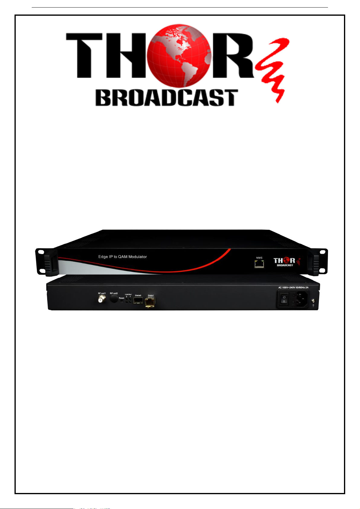
User Manua
l
H-IPRF-16QAM
Revision 2017
Thor Fiber 2016 Tel: (800) 521-8467 Email: [email protected] http://www.thorbroadcast.com
Page 2

H-IPRF-16QAM
A Note from Thor Broadcast about this Manual
Intended Audience
This user manual has been written to help people who have to use, integrate and to install the product. Some
chapters require some prerequisite knowledge in electronics and especially in broadcast technologies and
standards.
Disclaimer
No part of this document may be reproduced in any form without the written permission of Thor Broadcast.
The contents of this document are subject to revision without notice due to continued progress in methodology,
design and manufacturing. Thor shall have no liability for any error or damage of any kind resulting from the
use of this document.
Copy Warning
This document includes some confidential information. Its usage is limited to the owners of the product
that it is relevant to. It cannot be copied, modified, or translated in another language without prior written
authorization from Thor Broadcast.
Thor Fiber 2016 Tel: (800) 521-8467 Email: [email protected] http://www.thorbroadcast.com
Page 3

H-IPRF-16QAM
Table of Contents
CHAPTER 1 PRODUCT OVERVIEW .................................................................................................................. 1
1.1 OUTLINE .................................................................................................................................................. 1
1.2 KEY FEATURES .......................................................................................................................................... 1
1.3 GENERAL MAPPING ................................................................................................................................. 2
1.4 CARRIER SETTING ILLUSTRATION ............................................................................................................. 2
1.5 SPECIFICATIONS ....................................................................................................................................... 3
CHAPTER 2 - APPEARANCE............................................................................................................................. 4
2.1 FRONTAL VIEW: ....................................................................................................................................... 4
2.2 REAR PANEL ILLUSTRATION: ..................................................................................................................... 4
CHAPTER 3 INSTALLATION GUIDE .................................................................................................................. 5
3.1 IN THE BOX .............................................................................................................................................. 5
3.2 INSTALLATION PREPARATION ................................................................................................................... 5
3.2.1 DEVICE’S INSTALLATION FLOW CHART ILLUSTRATED AS FOLLOWS: .................................................... 5
3.2.2 ENVIRONMENT ..................................................................................................................................... 6
3.2.3 GROUNDING ......................................................................................................................................... 7
CHAPTER 4 WEB NMS MANAGEMENT ........................................................................................................... 8
4.1 LOGIN ...................................................................................................................................................... 8
4.2 OPERATION .............................................................................................................................................. 9
4.2.1 SUMMARY ............................................................................................................................................ 9
4.2.2 PARAMETERS ........................................................................................................................................ 9
CHAPTER 5 - TROUBLESHOOTING ................................................................................................................ 19
CHAPTER 6 PACKING LIST ......................................................................................................................... 20
Thor Fiber 2016 Tel: (800) 521-8467 Email: [email protected] http://www.thorbroadcast.com
Page 4

H-IPRF-16QAM
Chapter 1 Product Overview
1.1 Outline
The Thor Broadcast new Edge QAM Modulator is a new 1 RU chassis headend in a box that will
ingest IP feeds and convert to a QAM channel lineup of your choosing. The latest gen unit has an
inclusive chassis that no longer uses blades but does all necessary functioning preloaded to
successfully convert IP streams to 16 (or 32- model dependent) QAM channels to create your own
efficient IPTV headend into an RF headend. This powerhouse will scramble, multiplex, and modulate
up to 16 or 32 channels that supports a maximum 1024 IP TS streams through the 2 GE ports and
output 16 or 32 non-adjacent carriers (50MHz~960MHz) via the single RF output interface on the
rear of the unit. High performance encoding means you can now distribute countless channels into
the bandwidth of 16 QAM carriers.
1.2 Key Features
2 GE input, SFP interface
Supports up to 1024 channels TS over UDP/RTP, unicast and multicast, IGMP v2\v3
Max 840Mbps for each GE input
Accurate PCR adjusting
CA PID filtering, remapping and PSI/SI editing
Up to 180 PIDS remapping per channel
DVB general scrambling system (ETR289), simulcrypt standards ETSI 101 197 and ETSI 103 197
16 multiplexed or scrambled TS over UDP/RTP/RTSP output
16 non-adjacent QAM carriers output, compliant to DVB-C (EN 300 429) and ITU-T J.83 A/B
RS (204,188) encoding
NMS Web-based Network management
Thor Fiber 2016 Tel: (800) 521-8467 Email: [email protected] http://www.thorbroadcast.com
Page 5
H-IPRF-16QAM
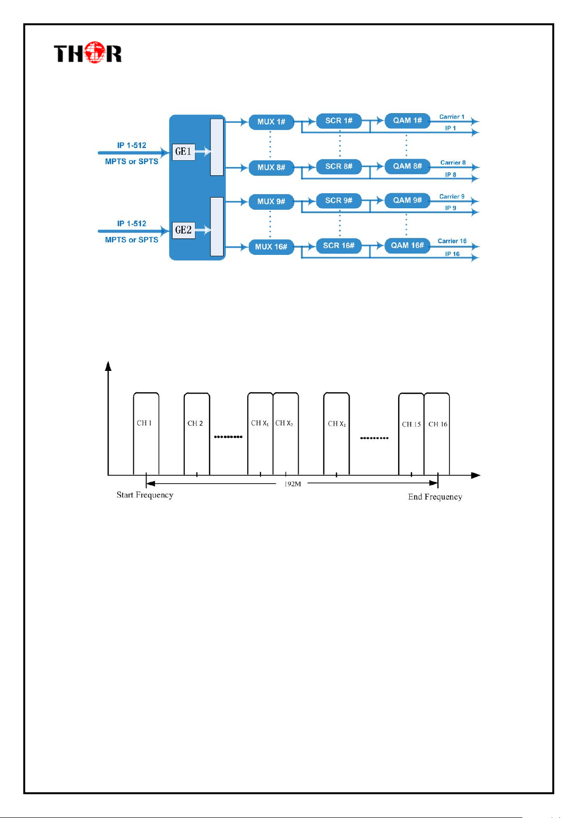
1.3 General Mapping
1.4 Carrier Setting Illustration
Thor Fiber 2016 Tel: (800) 521-8467 Email: [email protected] http://www.thorbroadcast.com
Page 6
H-IPRF-16QAM
Input
Input
512×2 IP input, 2 100/1000M Ethernet Port (SFP)
Transport Protocol
TS over UDP/RTP, unicast and multicast, IGMP
V2/V3
Transmission Rate
Max 840Mbps for each GE input
Mux
Input Channel
1024
Output Channel
16
Max PIDs
180 per channel
Functions
PID remapping(auto/manually optional)
PCR accurate adjusting
PSI/SI table automatically generating
Scrambling
Parameters
Max simulscrypt CA
4
Scramble Standard
ETR289, ETSI 101 197, ETSI 103 197
Connection
Local/remote connection
Modulation
Parameters
QAM Channel
16 non-adjacent carriers
Modulation Standard
EN300 429/ITU-T J.83A/B
Symbol Rate
5.0~7.0Msps, 1ksps stepping
Constellation
16, 32, 64, 128, 256QAM
FEC
RS (204, 188)
RF Output
Interface
1 F-type output port for 16 carriers, 75Ω
RF Range
50~960MHz, 1kHz stepping
Output Level
-20dBm~+10dBm(87~117dbµV), 0.1dB stepping
MER
≥ 40dB
ACLR
-60 dBc
TS output
16 IP output over UDP/RTP/RTSP, unicast/multicast, 2 100/1000M Ethernet
Ports
System
Network management software (NMS)
General
Demission
420mm×440mm×44.5mm (WxLxH) – 1RU
Weight
3kg
Temperature
0~45℃(operation), -20~80℃(storage)
Power Supply
AC 100V±10%, 50/60Hz or AC 220V±10%,
50/60Hz
Consumption
15.4W
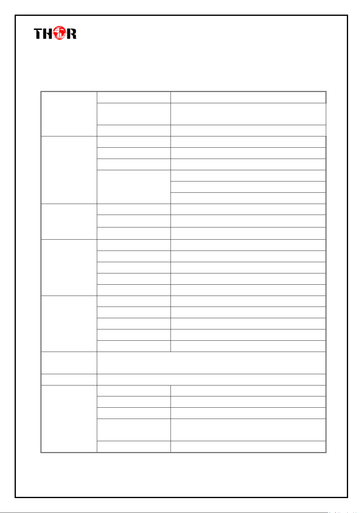
1.5 Specifications
Thor Fiber 2016 Tel: (800) 521-8467 Email: [email protected] http://www.thorbroadcast.com
Page 7
H-IPRF-16QAM
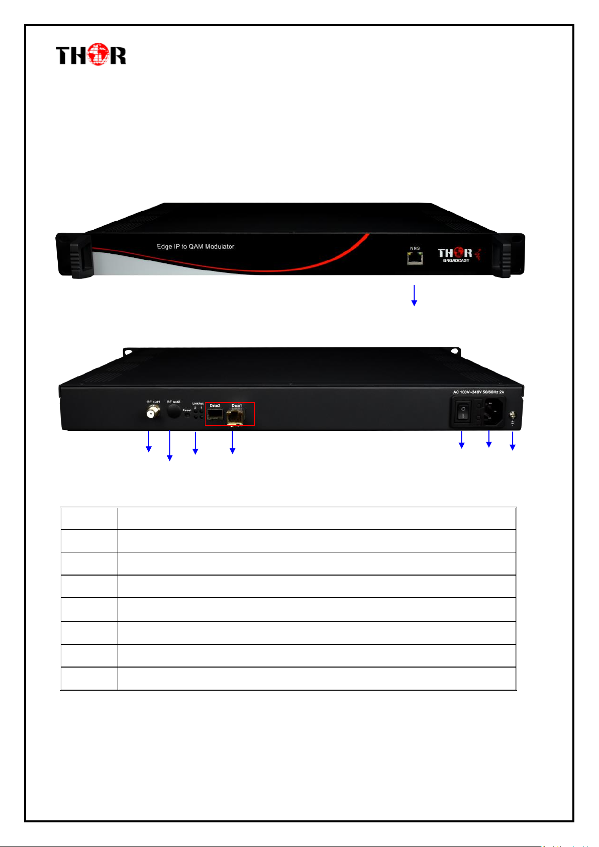
1
NMS/CAS: network management port and CA data port
2
RF output port
3
Reset IP: Reset webmaster IP address, recover to default IP address
4
Link/Act Indicators
5
Data Input/Output 1/2 (SFP)
6
Power switch
7
AC Power Socket
8
Ground
3 4 5
6
8
1
2
Chapter 2 - Appearance
2.1 Frontal View:
2.2 Rear Panel Illustration:
Thor Fiber 2016 Tel: (800) 521-8467 Email: [email protected] http://www.thorbroadcast.com
Page 8
H-IPRF-16QAM
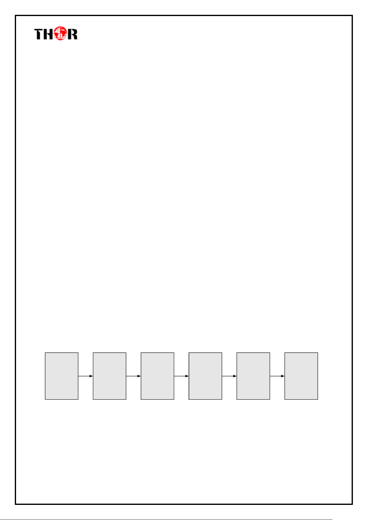
Connecting
Grouding
Wire and
Power
Cord
Acquisition
Check
Fixing
Device
Setting
Parameter
Running
Device
Connecting
Signal Wire
Chapter 3 Installation Guide
3.1 In the Box
When you open the Thor Edge QAM powerhouse, please check all items according to packing list.
Normally it should include the following items:
H-IPRF-16/32QAM
User’s Manual
Power Cord
If any item is missing with the list above, please contact Thor Broadcast – 1-800-521-8467
3.2 Installation Preparation
The main steps of the installation include:
Checking the possible device for missing pieces or damage from transport
Preparing relevant environment/rack for installation
Installing the IP to QAM Modulator
Connecting signal cables
Connecting communication port (if it is necessary) ; (it is necessary )
3.2.1 Device’s Installation Flow Chart Illustrated as follows:
Thor Fiber 2016 Tel: (800) 521-8467 Email: [email protected] http://www.thorbroadcast.com
Page 9

H-IPRF-16QAM
Item
Requirement
Machine Hall Space
When installing unit on rack, the distance between 2 rows of
machine frames should be 1.2~1.5m and the distance against
wall should be no less than 0.8m.
Machine Hall Floor
Electric Isolation, Dust Free, HVAC
anti-static material:1X10⁷~1X10¹⁰, Grounding current
limiting resistance: 1M (Floor bearing should be greater than
450Kg/㎡)
Environment
Temperature
5~40℃(sustainable ),0~45℃(short time),
installing air-conditioning is recommended
Relative Humidity
20%~80% sustainable 10%~90% short time
Pressure
86~105KPa
Door & Window
Installing rubber strip for sealing door-gaps and dual level
glasses for window
Fire Protection
Fire alarm system and extinguisher
Power
Device power, HVAC and lighting should be independent to
each other. Device power requires AC 110V±10%, 50/60Hz or
AC 220V±10%, 50/60Hz. Please carefully check before
running.
3.2.2 Environment
Thor Fiber 2016 Tel: (800) 521-8467 Email: [email protected] http://www.thorbroadcast.com
Page 10

H-IPRF-16QAM
3.2.3 Grounding
It is important to keep this device grounded to ensure all of the modules function
correctly. Correctly grounding the device will also help prevent any electrical interference,
lightening. Etc. Also it helps reject minor interference that may disrupt the devices ability to
function smoothly. General rule of them, make sure the device is grounded when installing
anywhere.
Always use copper wire. When applied correctly the ground must be wrapped well to
ensure maximum conduction so it can reduce any high frequencies. The copper ground wire
should also be as short and thick as possible
Installer must make sure that the two ends of the ground are well conducted and have
appropriate anti-rust properties.
It is prohibited to use any other device as part of the grounding electric circuit.
The area of the conduction between the ground wire and device’s frame should be no
less than 25 ㎡.
Thor Fiber 2016 Tel: (800) 521-8467 Email: [email protected] http://www.thorbroadcast.com
Page 11
H-IPRF-16QAM
Chapter 4 Web NMS Management
This is literally how you control the device; there is no front interface with D-Pad
4.1 Login
The factory default IP address is 192.168.0.136 and users can connect the device and web NMS
through this IP address.
Connect the PC (Personal Computer) and the device with a net cable, and use ping command to
confirm they are on the same network segment. For instance, the PC IP address is 192.168.99.252,
we then change the device IP to 192.168.99.xxx (xxx can be 0 to 255 except 252 to avoid IP conflict).
Launch the web browser an input the device IP address in the browser’s address bar and press Enter.
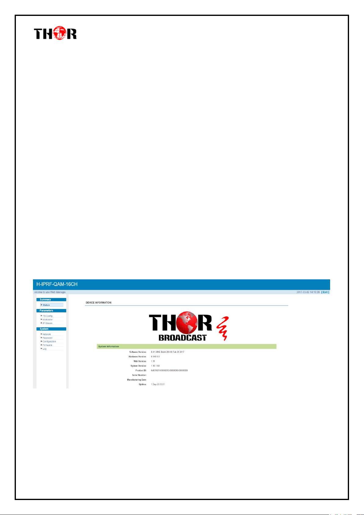
It will display the Login interface as Figure-1. Input the Username and Password (Both the default
Username and Password are “admin”. And then click “Login” to start the device setting.
This is the front splash screen with details on your unit – Status & Summary
Figure-1
Thor Fiber 2016 Tel: (800) 521-8467 Email: [email protected] http://www.thorbroadcast.com
Page 12
H-IPRF-16QAM
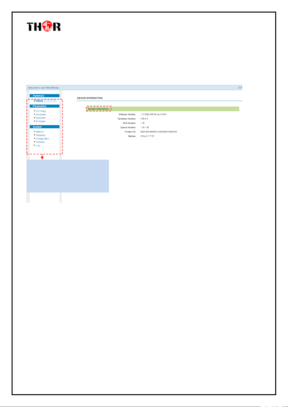
Click any item here to enter the
corresponding interface to
check information or set the
parameters.
4.2 Operation
4.2.1 Summary
When we confirm the login, it displays the summary interface as Figure-2.
Figure-2
4.2.2 Parameters
Parameters → TS Config:
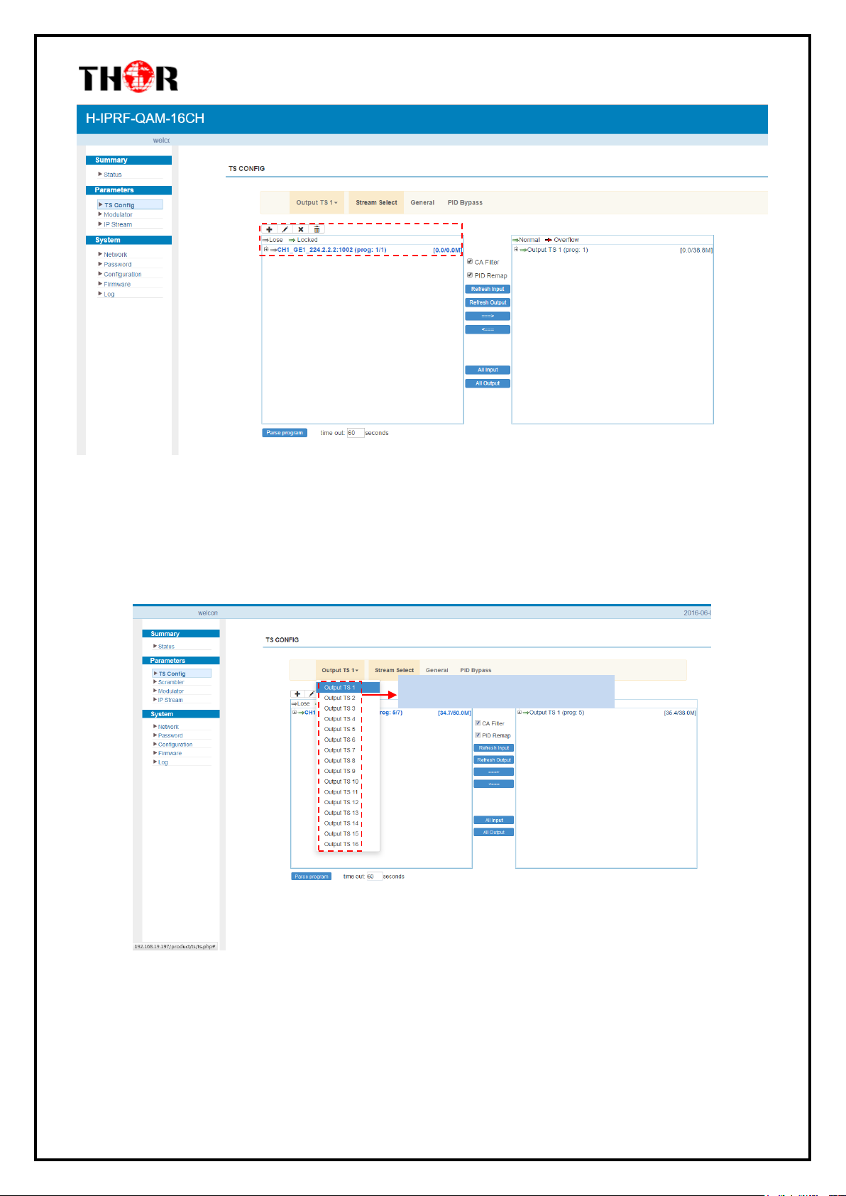
Click “TS Config”, it displays the interface where users can configure the output TS parameters in
this interface. (Figure-3)
Thor Fiber 2016 Tel: (800) 521-8467 Email: [email protected] http://www.thorbroadcast.com
Page 13
H-IPRF-16QAM
To select output TS channel 1-16
Figure-3
Output TS X
From the menu on top of the webpage, click “Output TS X”, it’ll display the interface as in
Figure-4. Select the output TS channels.
Stream Select
From the menu on top of the webpage, click “Stream Select”, it displays the interface where
you can choose the programs to Mux. (Figure-5)
Thor Fiber 2016 Tel: (800) 521-8467 Email: [email protected] http://www.thorbroadcast.com
Figure-4
Page 14
H-IPRF-16QAM
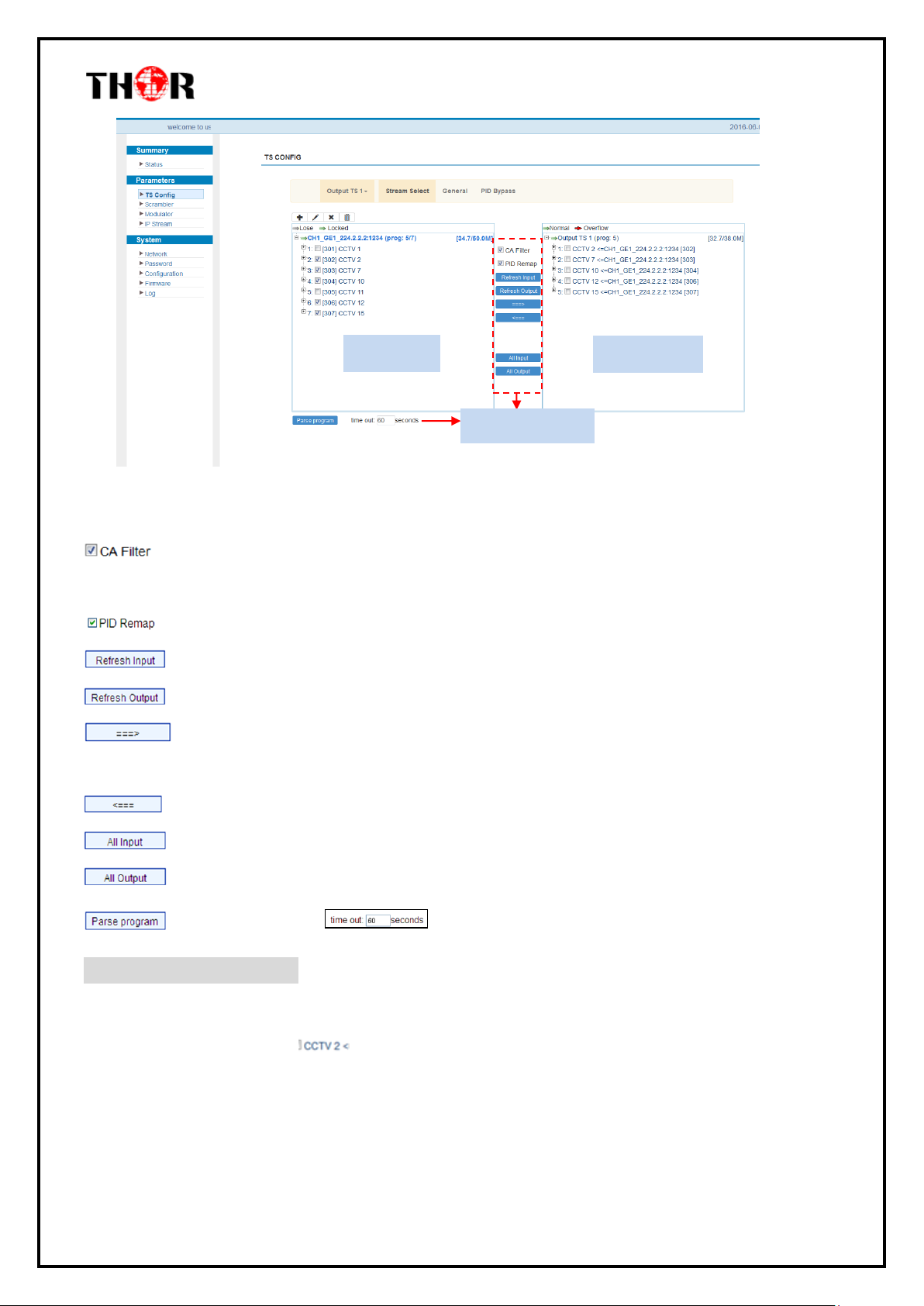
Input Area
Output Area
Operation Area
Figure-5
Configure ‘Input Area’ and ‘Output Area’ with buttons in ‘Operation Area’. Instructions are as below:
:Enable/disable the CA Filter function. By clicking the box, you can filter the input CA to
avoid disturbing the devices scrambling function.
: To enable/disable the PID remapping
Refresh the input program information
Refresh the output program information
Select one input program first and click this button to transfer the selected program to
the right box to output.
You can cancel the multiplexed programs from the right box.
To select all the input programs
To select all the output programs
To parse programs time limitation of parsing input programs
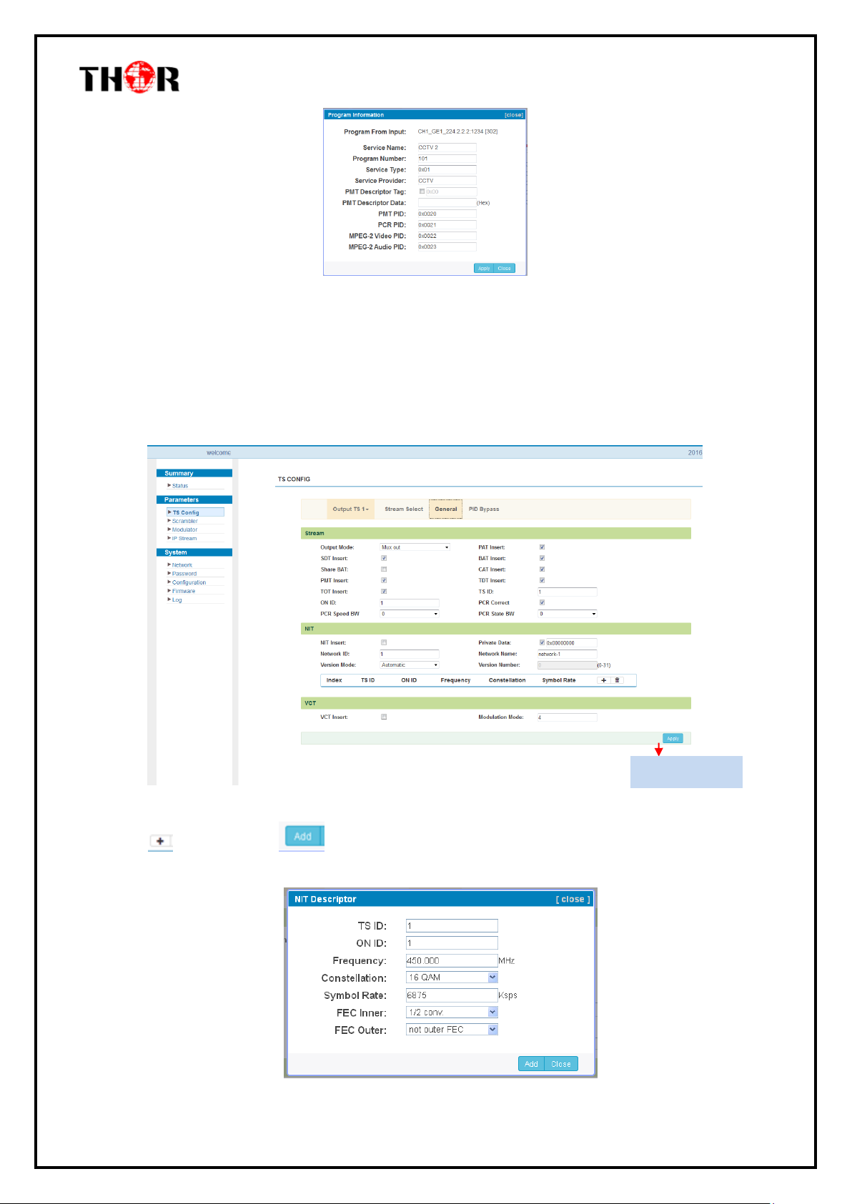
Program Modification:
The multiplexed program information can be modified by clicking the program in the ‘output’ area.
For example, when clicking , it triggers a dialog box (Figure 6) where you can input new
information.
Thor Fiber 2016 Tel: (800) 521-8467 Email: [email protected] http://www.thorbroadcast.com
Page 15
H-IPRF-16QAM
Add description
Figure 6
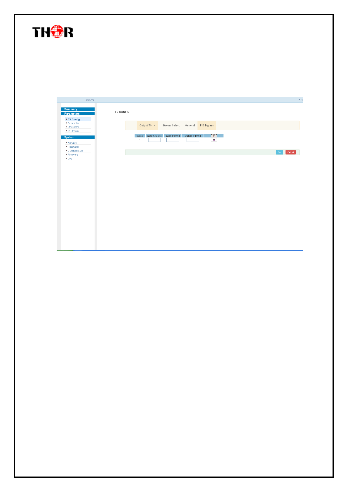
General
From the menu on the top of the webpage, click “General”, it displays the interface where you can
set parameters for each output channel. (Figure-7)
Thor Fiber 2016 Tel: (800) 521-8467 Email: [email protected] http://www.thorbroadcast.com
Figure-7
Click and then click to apply the modified parameters.(Figure-8)
Page 16
H-IPRF-16QAM
Figure-8
PID Pass
From the menu on the top of the webpage, click “PID Pass”, to display the interface where to add
the PIDs which need pass through. (Figure-9)
Figure-9
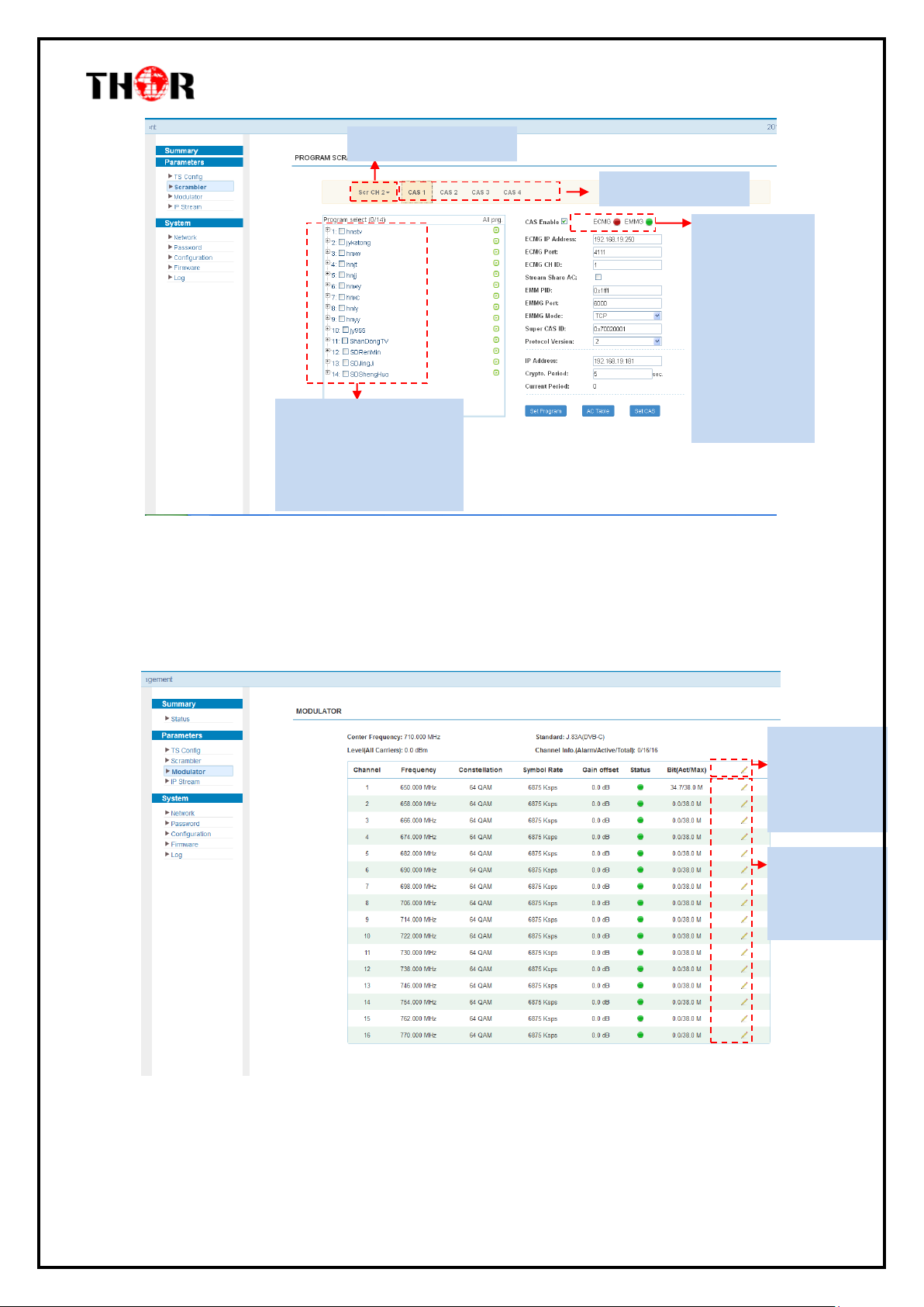
Parameters → Scrambler:
From the menu on left side of the webpage, clicking “Scrambler”, it displays the interface where
users can choose the programs to scramble. (Figure-10)
Thor Fiber 2016 Tel: (800) 521-8467 Email: [email protected] http://www.thorbroadcast.com
Page 17
H-IPRF-16QAM
This field indicates the
current outputting
programs. The programs
selected will be scrambled.
Scramble channel select
CA channel select
EMMG and
ECMG working
state, green
means it works
normally, while
red means
communication
error or no
communication.
Click to set each
channel RF QAM
output
Click to set all
channels RF
QAM output
parameters
Figure-10
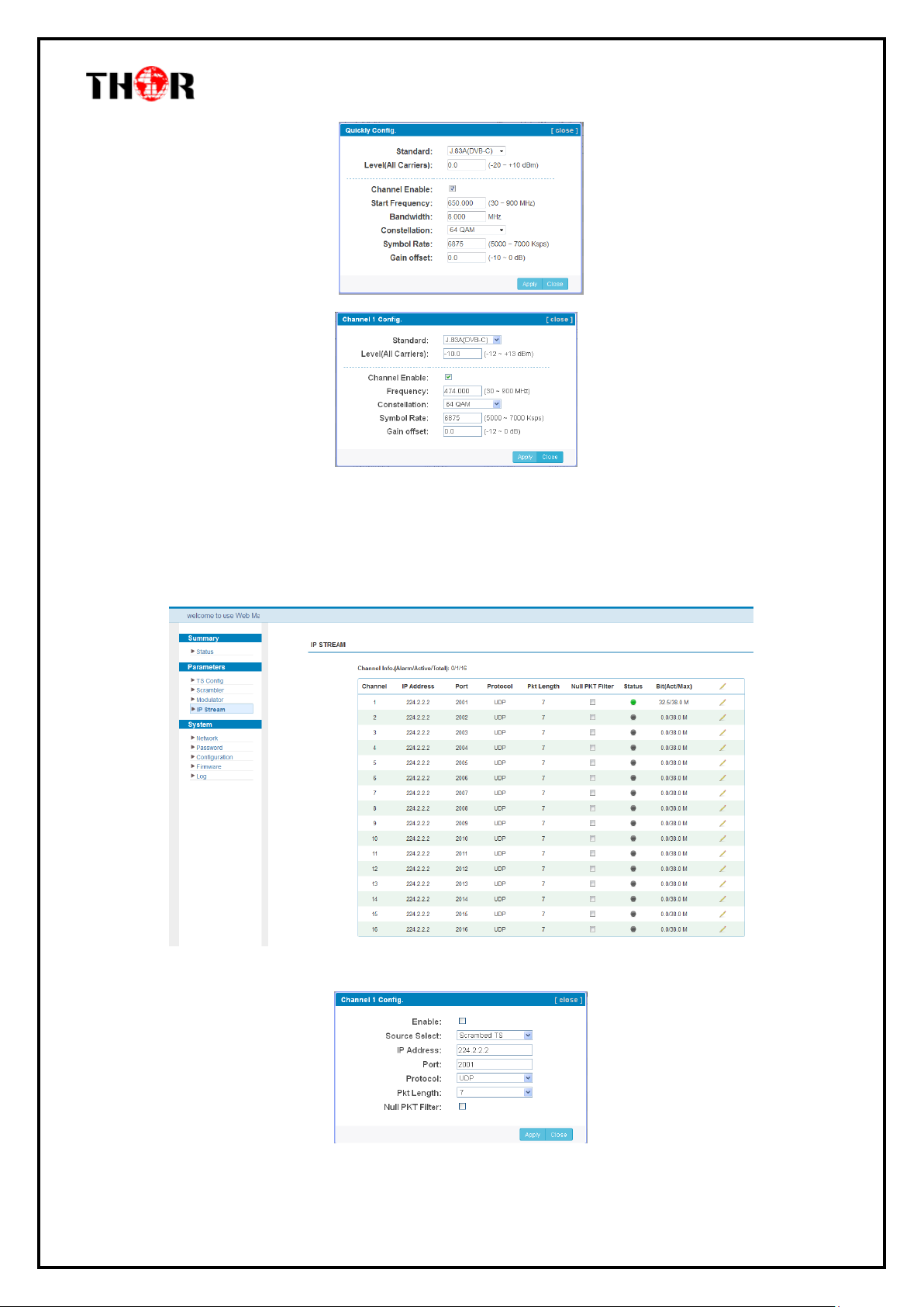
Parameters → Modulator:
From the menu on left side of the webpage, click ‘Modulator’, it will display the interface as shown
in Figure-11 where to set RF output parameters.
Thor Fiber 2016 Tel: (800) 521-8467 Email: [email protected] http://www.thorbroadcast.com
Figure-11
Page 18
H-IPRF-16QAM
Parameters → IP Stream:
Thor’s Edge QAM supports TS to output in IP (16*MPTS) format through the DATA port.
Click ‘IP Stream’, it will display the interface as shown in Figure-12 where to set IP out parameters.
Figure-12
Thor Fiber 2016 Tel: (800) 521-8467 Email: [email protected] http://www.thorbroadcast.com
Page 19
H-IPRF-16QAM
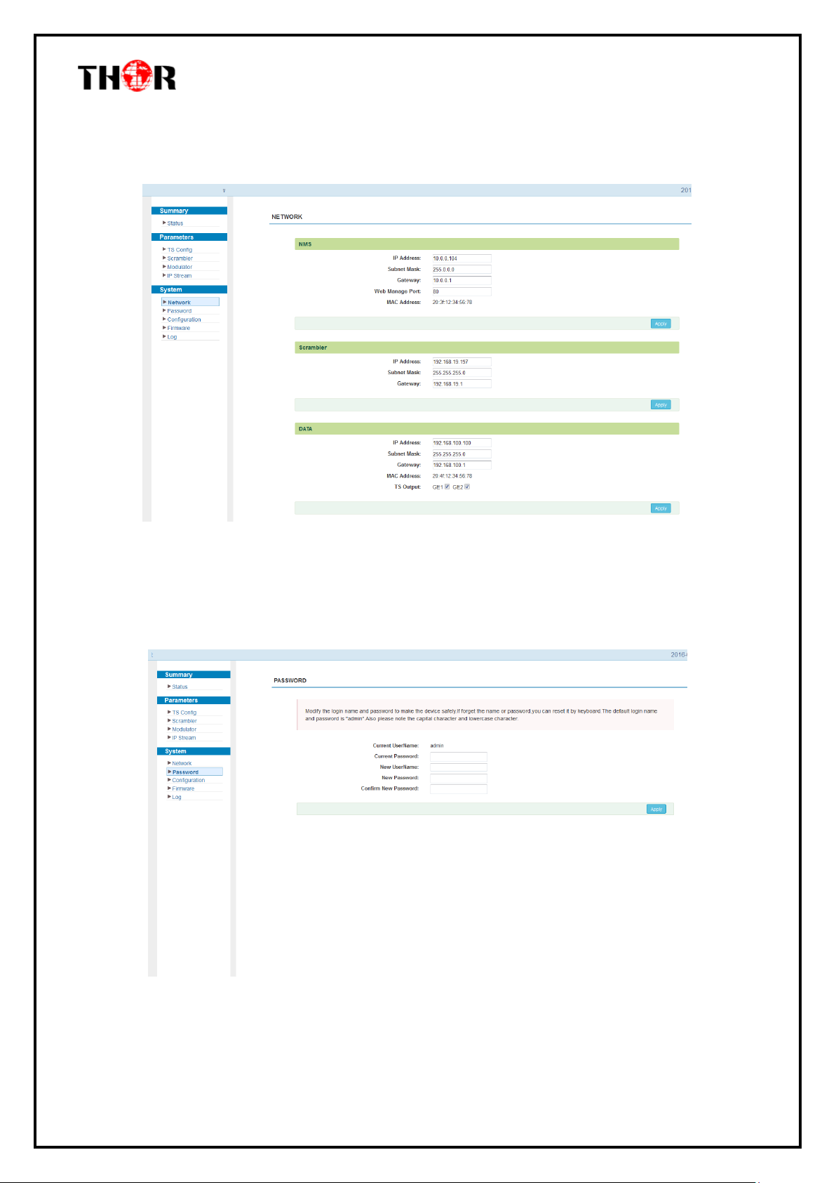
System → Network:
Click ‘Network’, it will display the interface as shown in Figure-13 where to set network parameters.
Figure-13
System → Password:
From the menu on left side of the webpage, click “Password”, it will display the screen as shown in
Figure-14 where to set the login account and password for the web NMS.
Figure-14
Thor Fiber 2016 Tel: (800) 521-8467 Email: [email protected] http://www.thorbroadcast.com
Page 20
H-IPRF-16QAM
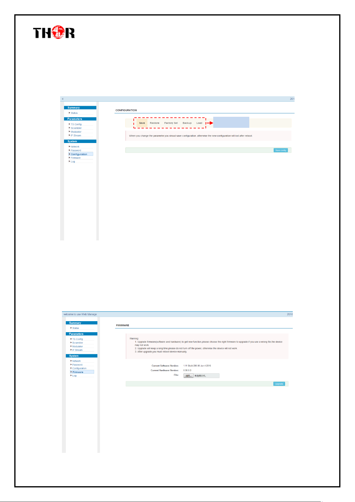
Select areas
System → Configuration:
From the menu on left side of the webpage, click “Configuration”, it will display the screen as Figure-
15 where to set your configurations for the device.
Figure-15
System → Firmware:
From the menu on left side of the webpage, click “Firmware”, it will display the screen as shown in
Figure-16 where to update firmware for the device.
Thor Fiber 2016 Tel: (800) 521-8467 Email: [email protected] http://www.thorbroadcast.com
Page 21
H-IPRF-16QAM
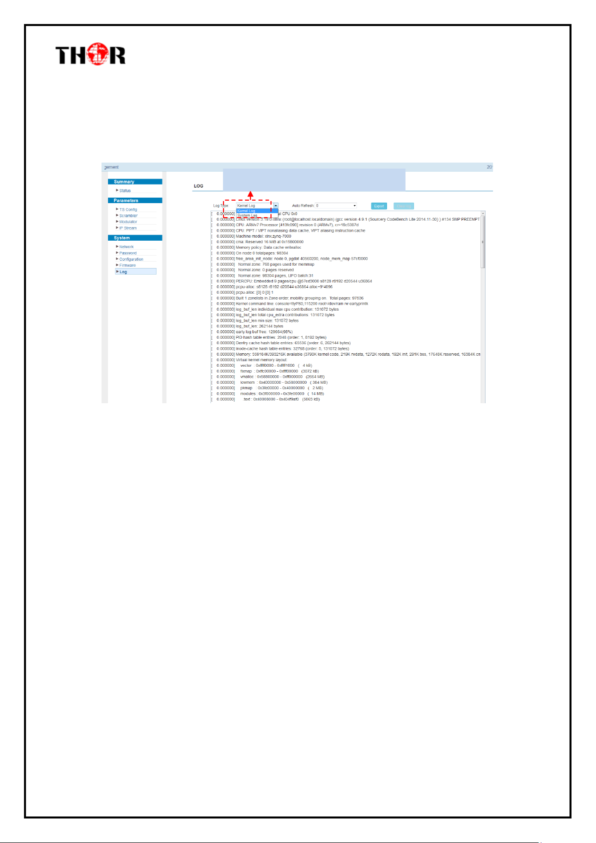
To select “Kernel log” and “System Log”
Figure-16
System → Log:
From the menu on left side of the webpage, click “Log”, it will display the screen as shown in
Figure-17 where to check the “Log”.
Figure-17
Thor Fiber 2016 Tel: (800) 521-8467 Email: [email protected] http://www.thorbroadcast.com
Page 22

H-IPRF-16QAM
Chapter 5 - Troubleshooting
THOR’s ISO9001 quality assurance system has been approved by the CQC organization. We
guarantee the products’ quality, reliability and stability. All THOR products haven passed all
testing and manual inspections before they are shipped out. The testing and inspection scheme
already covers all the Optical, Electronic and Mechanical criteria which have been published
by THOR. To prevent a potential hazard, please strictly follow the operation conditions.
Prevention Measures
Installing the device in a place where the environmental temperature is between 0 to
45 °C
Making sure the unit has plenty of ventilation for the heat-sink on the rear panel; and
other heat-sink bores if necessary
Checking the AC input within the power supply and ensure it is working, the
connection is correctly installed before switching on device
Checking the RF output levels to stay within a tolerable range, if it is necessary
Checking all signal cables have been properly connected
Frequently switching on/off device is prohibited; the interval between every switching
on/off must be greater than 10 seconds.
Conditions needed to unplug power cord
Power cord or socket damage.
Any liquid that got into the device.
Any stuff that could cause a circuit short
Device in damp environment
Device has suffered from physical damage; i.e. it fell off a rack.
Longtime idle.
After switching on and restoring to factory setting, device still won’t work properly.
Maintenance needed on device
Thor Fiber 2016 Tel: (800) 521-8467 Email: [email protected] http://www.thorbroadcast.com
Page 23

H-IPRF-16QAM
Chapter 6 Packing list
Thor Broadcast IP QAM Modulator 1 pc
User’s Manual 1 pc
Power Cord 1 pc
Thor Fiber & Thor Broadcast
Los Angeles CA
1-800-521-8467 ext 2 for Support
Thor Fiber 2016 Tel: (800) 521-8467 Email: [email protected] http://www.thorbroadcast.com
 Loading...