

Page 1

DVB-ASI Over IP
Bi-Directional Gateway
User’s manual
H-1ASI-IP-B
Page 2

Catalog
1111
SAFETY INSTRUCTION ············································································································································· 1
2222
System structure and principle ····························································································································· 2
2.1
System structure ······································································································································ 2
2.2
Working principle ····································································································································· 2
3333
Specifications ···································································································································································· 3
3.1
ASI Interface············································································································································· 3
3.2
Network port ·············································································································································· 3
3.3
Power failure auto save ·························································································································· 4
3.4
Power ························································································································································ 4
3.5
Working environment ······························································································································ 4
3.6
Mechanics················································································································································· 4
3.7
Weight ······················································································································································· 5
4444
Equipment connection ··················································································································································· 5
4.1
Front panel and keybord ························································································································ 5
4.1.1
Front panel ······································································································································· 5
4.2
Front panel ··············································································································································· 5
4.3
Rear panel ················································································································································ 6
5555
Operations ········································································································································································· 6
5.1
Keybord ····················································································································································· 6
5.2
Menu ·························································································································································· 7
5.2.1
Lock status ······································································································································· 7
Page 3

5.2.2
5.2.3
Main Menu········································································································································ 7
Basic parameters ···························································································································· 7
5.2.3.1
5.2.3.2
5.2.3.3
5.2.4
5.2.5
5.2.6
5.2.7
5.2.8
5.2.9
6666
SYSTEM FAILURE OR TROUBLE SHOOTING ······························································································ 12
6.1
6.2
6.2.1
6.2.2
6.2.3
Output ······································································································································· 8
Input ·········································································································································· 9
Local ········································································································································· 9
Network setting ······························································································································ 10
Save current settings ···················································································································· 10
Load settings·································································································································· 11
Version No. ····································································································································· 11
Language setting(English) ······································································································ 11
Error info ········································································································································· 11
INDICATOR status ································································································································ 12
Trouble shooting ···································································································································· 12
POWER” INDICATOR OFF ········································································································· 12
“ERROR” ON (RED) ····················································································································· 12
AS1 and IP indicator ON ·············································································································· 12
7777
NMS Operation ···························································································································································· 13
Page 4

1
1 SAFETY INSTRUCTION
11
● Read manual carefully before use.
● Do not open the case and touch internal components for safety and warranty
● Pull out power plug in case of long time standby .Do not use faulty power plug or
power supply to avoid fire or electric shock.
● Do not touch power supply with wet hands.
● Handle with care when pulling out power plug, no touch with the wire.
● No flammable or liquid allowed into device.
● Do not install Encoder in hot area or strong sunshine or dusty place.
● Shock-proof is a must.
● Room with good ventilation is required.
● Keep original packing material for future possible transportation.
1111
Page 5
DATA
ASI OUT
CPU
LED Keybo
Network
LCD
ASI IN
2
2 System structure and principle
22
2.1
2.1 System structure
2.12.1
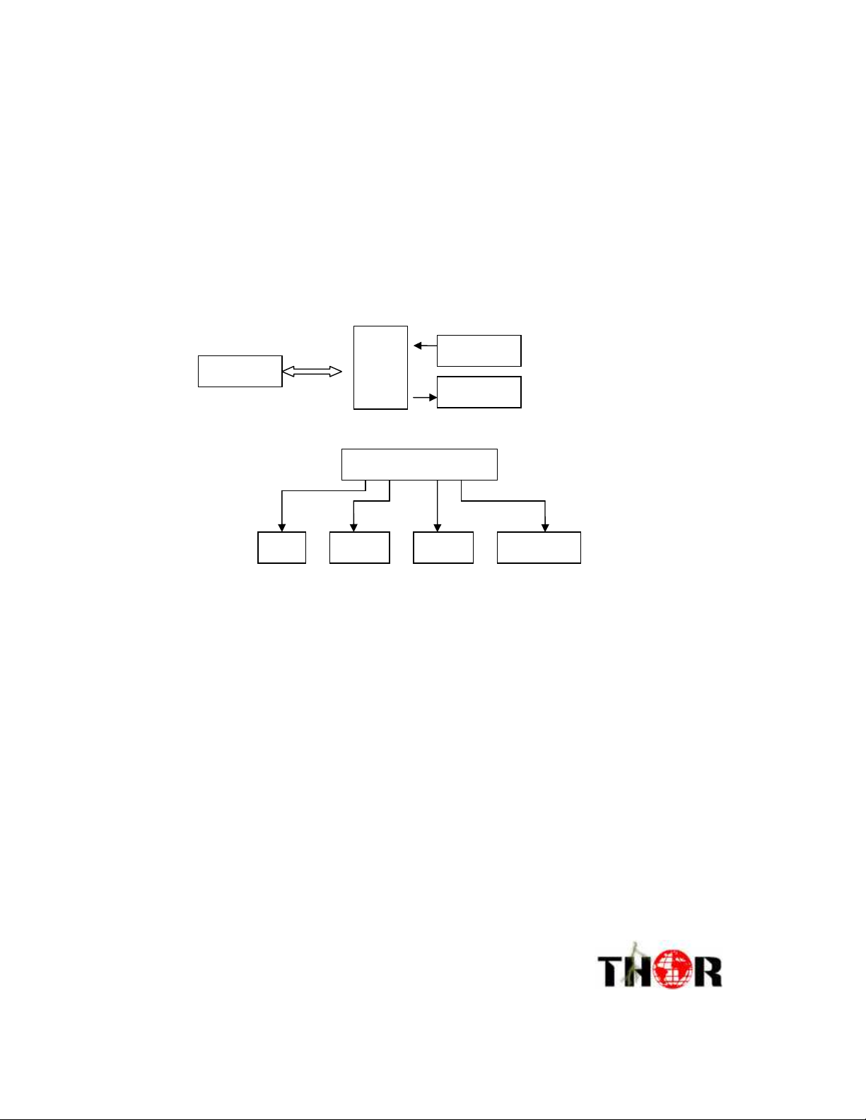
IP adaptor structure as below:
Data
proce
ss
2.2
2.2 Working principle
2.22.2
The H-1ASI-IP-B unit consists of an ASI input/output module, an Ethernet IP
output/input module, and a CPU module. An ASI Transport Stream that is input into
the ASI module is encapsulated by the CPU and output by the Ethernet module. The
opposite process takes place at the receiving end.
.
.
. .
2222
Page 6

3333
3
3 Specifications
33
3.1
3.1 ASI Interface
3.13.1
Input port: 2 routs DVB ASI port
Connector:BNC
Impedance:75Ω
TS standard:ISO13818-1
Input effective bit rate:max 214Mbps(each route)
TS packet format:188/204bytes(auto recognition )
TS input mode: CBR /BURST/VBR
3.2
3.2 Network port
3.23.2
There are two network ports on the H-1ASI-IP-B.
Data Port: The RJ-45 Port labeled “Data” is the transport port for the
encapsulated ASI stream. This port carries the primary IP address for the device, and
is the only port that needs to be connected for the device to function. It is important to
note that the Data port IP address does not support the “ping” function. It is also
important to note that when making changes to the IP configurations either via front
panel or NMS it is important to use the “Save Config” option on the top menu when on
the front panel, or click the “Save Config” button in the software when using NMS.
Ethernet Port: This port is for network management via the Network
Management Software. It is not essential for this port to be connected for proper
functioning of the device. However the Network Management Software is the most
effective method for setting the devices IP address. If problems arise while attempting
to set the device IP with the front panel please use the network management software.
Page 7

4444
If network management and monitoring is desired, this port can be connected to the
same network as the primary Data port. Please note that these two ports have
separate IP address and are configured differently.
Ethernet port:IEEE802.3 Ethernet ,RJ45 port
Software protocol:UDP/IP
3.3
3.3 Power failure auto save
3.33.3
Enabled by default, this setting automatically saves the system parameters in the event
of a power failure.
3.4
3.4 Power
3.43.4
Voltage 90V~250VAC
Frequency 50Hz±2%
Power 20W
3.5
3.5 Working environment
3.53.5
Temperature +5°C~45°C
Storage -25°C~+55°C
Humidity 10~75%
3.6
3.6 Mechanics
3.63.6
44.5mm(H,1U)×483mm(W,19″)×410mm(D)
Page 8
8
7
1 2 3 4 5 6
ASI Lock
3.7
3.7 Weight
3.73.7
5kg
The above specifications are subject to change without notice.
4
4 Equipment connection
44
4.1
4.1 Front panel and keyboard
4.14.1
4.1.1
4.1.1
Front panel
4.1.14.1.1
Power indicator
Error indicator
4.2
4.2 Front panel
4.24.2
IP Adaptor
IP Adaptor
IP AdaptorIP Adaptor
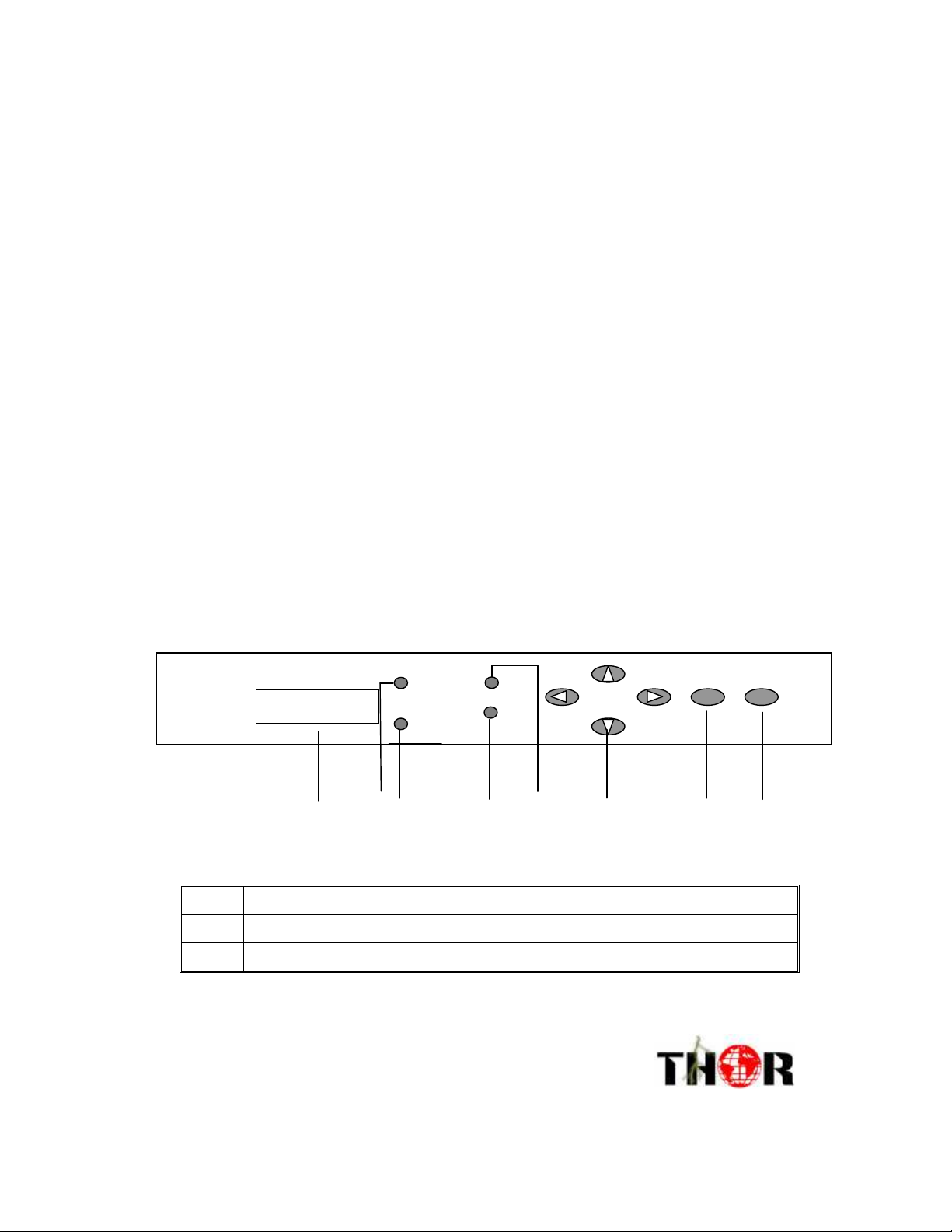
1 LCD Display
2 Error indicator
3 Power indicator
IP Lock
Power
Error
Enter Exit
5555
Page 9
4.3
6
5 4 3 2 1
Ether
100M
CAT
ASI OUT1
DATA
ASI OUT2
ASI IN1
4.3
4.34.3
4.4
4.4
4.44.4
4 Direction key
5 Confirm
6 Exit
7 ASI indicator
8 IP indicator
Rear panel
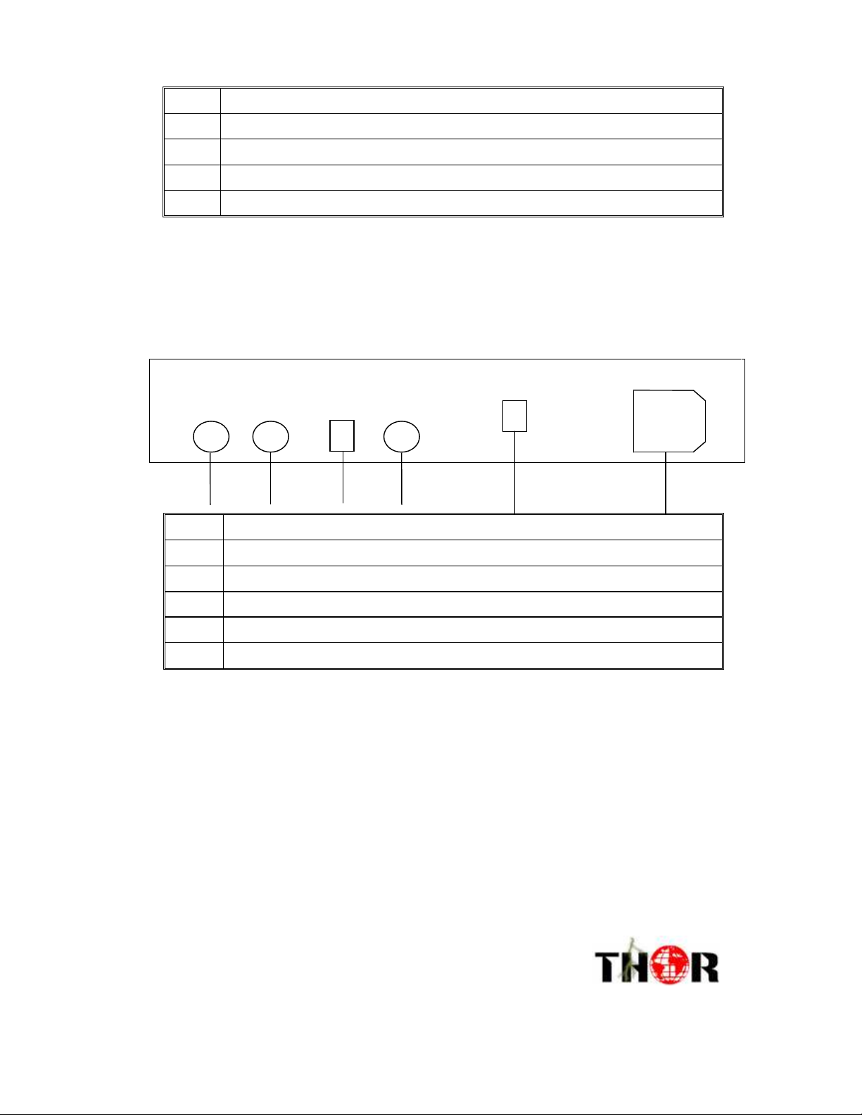
1 ASI output 1
2 AS1output2
3 Ethernet data port
4 ASI Input
5 Ethernet control port
6 Power switch
5
5 Operations
55
180-250v 50HZ 0.5A
5.1
5.1 Keyboard
5.15.1
The front key panel and LCD can be used to make local changes to the device
configuration. The arrow keys, and enter and exit are used to make these
changes. Please note that after any changes are made, you must save the
changes via the "Save Config" option in the root menu. If you do not use the
"Save Config" function, all changes will be lost on the next system reboot.
Page 10

ENTER (ENTER):confirm and operate ;
Exit (Exit ):back to upper menu or cancel the setting
Note :
A、press ENTER and exit to unlock if device is in lock status
B、keyboard auto lock if standby till 60 seconds
C、in lock status, press “down” to see IP menu
5.2
5.2 Menu
5.25.2
5.2.1
5.2.1
Lock status
5.2.15.2.1
ASI—IP Adaptor
5.2.2
5.2.2
Main Menu
5.2.25.2.2
00.000 mbps 00.000 mbps
After initializing, the LCD display following menu
1. Parameter Settings
2. Network Settings
3. Save Config
4. Load Config
5. Version No.
6. Language
7. Error Info
5.2.3
5.2.3
5.2.35.2.3
The Parameter Settings menu is for setting IP addresses and parameters for
the Transport Stream network port. This is the port that carries the ASI
TS over the IP network. This is different from the managment port, used for
the network managment software. Please remember that the IP address used
for TS send and TS recieve will not respond to the ping command.
Parameter Settings
Page 11

224.002.002.002
The Parameter Settings menu has the following options
5.2.3.1
5.2.3.1
5.2.3.15.2.3.1
Output
This Menu is used to enable
TS Output from the unit, and
to set the destination address
and port of the remote unit
5.2.3.1.1
ON/OFF
This option enables or disables
Transport Stream output
from the unit
1.1. Output
1.2. Input
1.3. Local
1.1.1.on/off
1.1.2. Destination IP
1.1.3. Destination port
1.1.1.on/off
off
5.2.3.1.2
Use this menu to set the
destination IP address
for the unit recieving the
ASI stream.
5.2.3.1.3
Use this menu to set the
port to be used to connect
to the receiving unit
Destionation IP
1.1.2. Destination IP
Destination port
.
.
. .
1.1.3. Destination port
1234
8888
Page 12

5.2.3.2
255.255.255.000
5.2.3.2
5.2.3.25.2.3.2
Input
This menu controls Transport
Receiving related settings
5.2.3.2.1
On/Off
This menu turns Transport
Stream receiving on or off
5.2.3.2.2
Receiving port
This sets the port number that
the transport stream will be
received on
5.2.3.3
5.2.3.3
5.2.3.35.2.3.3
Local
This menu is responsible
for setting the local IP
address and settings for
the Transport Stream
Ethernet port
1.2.1. on/off
1.2.2. receiving port
1.2.1.On/off
off
1.2.2. Receiving port
1234
1.3.1. Local IP
1.3.2.Gateway
1.3.3 Submask
1.3.4 Local MAC
5.2.3.3.1
Local IP
This sets the local IP
address for the Transport
Stream (TS) port
5.2.3.3.2
Gateway
This is used to specify a
gateway when a router is
in use
5.2.3.3.3
Submask
This menu sets the local IP
address subnet mask value
.
.
. .
1.3.1.local IP
192.168.000.195
1.3.2.Gateway
192.168.000.001
1.3.3.Submask
9999
Page 13

10
1010
10
5.2.3.3.4
Local MAC
This menu is used to set a
MAC hardware address for
the Local IP TS Port
5.2.4
5.2.4
Network setting
5.2.45.2.4
1.3.4. Local MAC
00-08-10-18-20-29
This menu is used to set parameters for the MANAGMENT port. The managment port
is a seperate Ethernet port used to remotely manage the gateway. This address will
respond to the ping command.
This sets the IP address
for the Network
3.1 IP address
Managment Software
(NMS) Ethernet Port
192.168.000.254
This sets the Subnet
Mask value for the
NMS Port
3.2 Submask
255.255.255.000
This sets the Default
Gateway for the NMS
Port when a router
is used
3.3 Gateway
192.168.000.001
This sets the UDP port
to be used with NMS
managment
3.4 UDP port
2009
This is used to change the
hareware MAC address
for the NMS Ethernet Port
3.5 MAC address
00-10-14-17-02-57
5.2.5
5.2.5
Save current settings
5.2.55.2.5
Press enter in this option to save settings
.
.
. .
Page 14

11
1111
11
5.2.6
5.2.6
Load settings
5.2.65.2.6
Wait.....
In this menu, the LCD displays as below:
6.1 load settings
5.2.7
5.2.7
Version No.
5.2.75.2.7
6.2 factory default
Here LCD displays the software and hardware number:
Software:1.03
Hardware:1.02
5.2.8
5.2.8
Language setting
5.2.85.2.8
((((
English
))))
Here you can select languages
8 Languages
English
After all settings, the system runs normally
5.2.9
5.2.9
Error info
5.2.95.2.9
in this menu the system will display any error information
.
.
. .
Page 15

12
1212
12
6
6
SYSTEM
66
6.1
6.1
6.16.1
FAILURE OR TROUBLE SHOOTING
INDICATOR
status
9 Error info
Blank
2 LED Indicators work as below
1“POWER” green means power supply normal
3“ERROR” red ,means device working abnormal
6.2
6.2 Trouble shooting
6.26.2
6.2.1
6.2.1 POWER” INDICATOR OFF
6.2.16.2.1
Check power cable, plug and switch
6.2.2
6.2.2
“ERROR” ON (RED)
6.2.26.2.2
If the device is working abnormally, please check the device error info.
If “unlock” alarm is displayed, this means the ASI signal input is abnormal.
Please check the ASI input signal source and cable.
6.2.3
6.2.3
AS1 and IP indicator ON
6.2.36.2.3
AS1 and IP on means the device is working normally
.
.
. .
Page 16

13
1313
13
7
7 NMS Operation
77
With the Network Management Software (MNS) the user can set all the parameters
on a PC and transfer the data to the device. This is the recommended technique for
setting parameters such as IP and Port number. To use the NMS software, connect
the Ethernet port on a computer to the “Ethernet” port on the device. Determine the
units “Local IP” address through the front panel. This is the IP that is found under
the “Network Settings” menu, not the IP’s found under “Parameter Settings”
menu. The local IP for the “Ethernet” Management port can also be changed via
the “Network Settings” Menu. To change the IP, press enter while the IP is being
displayed. The curser will appear, and the arrows can be used to set the new IP.
Press enter to confirm the new IP. Remember to always “Save Parameters” on the
home menu after making any changes. Make sure that the computer IP range is in the
same range and the devices IP address to ensure proper communication.
Once the management local IP is determined or set, launch the Network
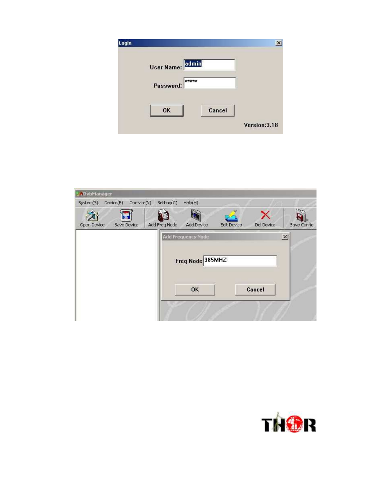
Management Software (NMS). Log into the software with username “admin” and
password “admin”. These can be changed from inside the software later.
.
.
. .
Page 17
14
1414
14
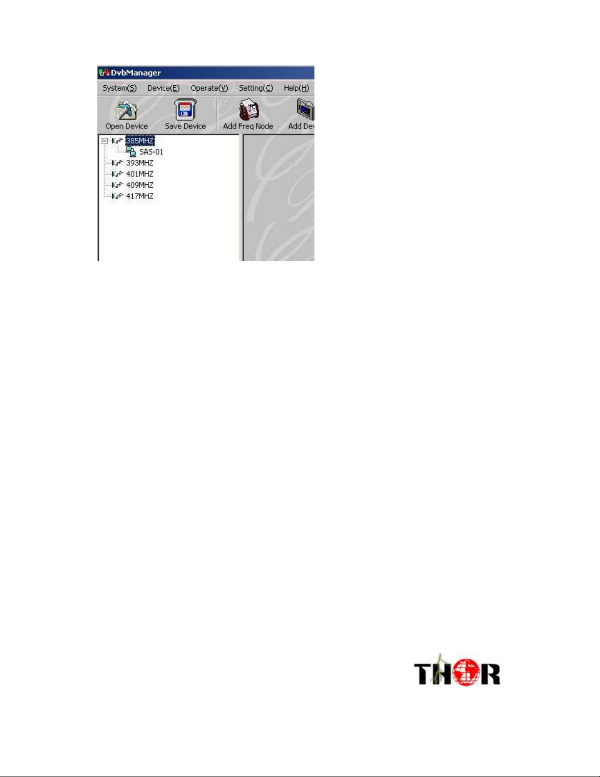
Once the main NMS menu comes up, Select “Add Freq Node” and you will see the
following dialog box:
In the “Add Frequency Node” Dialog box enter 385MHZ and hit ok. You will then see
the option populate in left hand menu tree.
.
.
. .
Page 18
15
1515
15
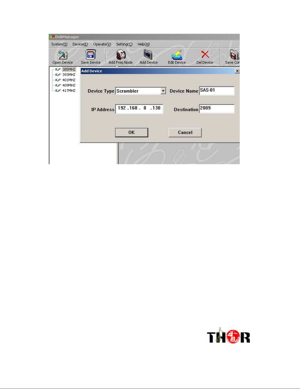
Select the 385MHZ option and click “Add Device”. The dialog will show up. Select
the “TS IP Gateway” option in the device type drop down menu and enter the Devices
management IP address. Give the device a name, and select the Management Port
number.
.
.
. .
Page 19
16
1616
16
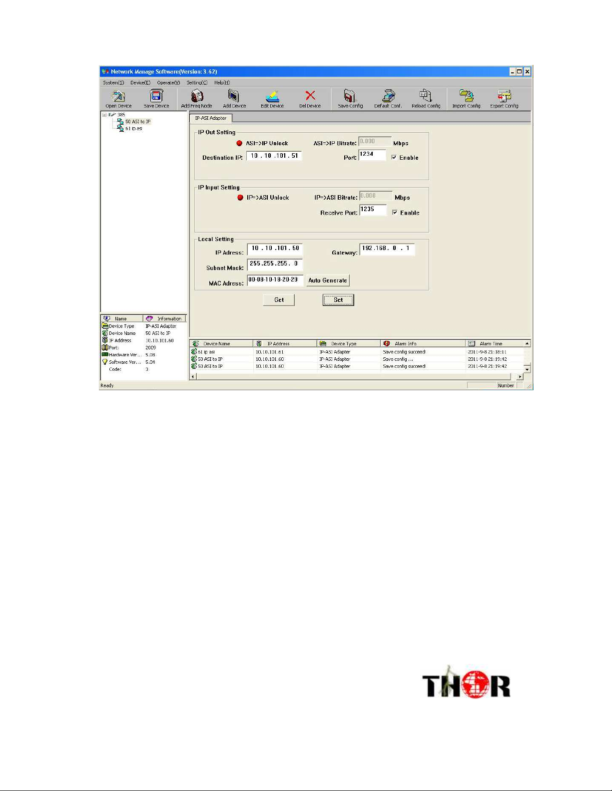
The device should now appear in the left hand menu tree. The device is now available
for the “open device” button. When you click open device all the parameters for the
device are now available for you to edit inside the software. You can click the “Get”
button to pull all of the current parameters from the device. You can make changes
then in the software and then click the “Set” button to write those parameters back to
the device. Once you have set the parameters it is important to click the “Save Config”
button on the top menu to make your changes permanent.
.
.
. .
Page 20
17
1717
17
You can also save configurations with this software as well as load your saved
configurations. Device status, Link Status, and ASI status are all visible from this
menu. You can also read the ASI Bitrate.
IP NMS menu
.
.
. .
 Loading...