

Page 1
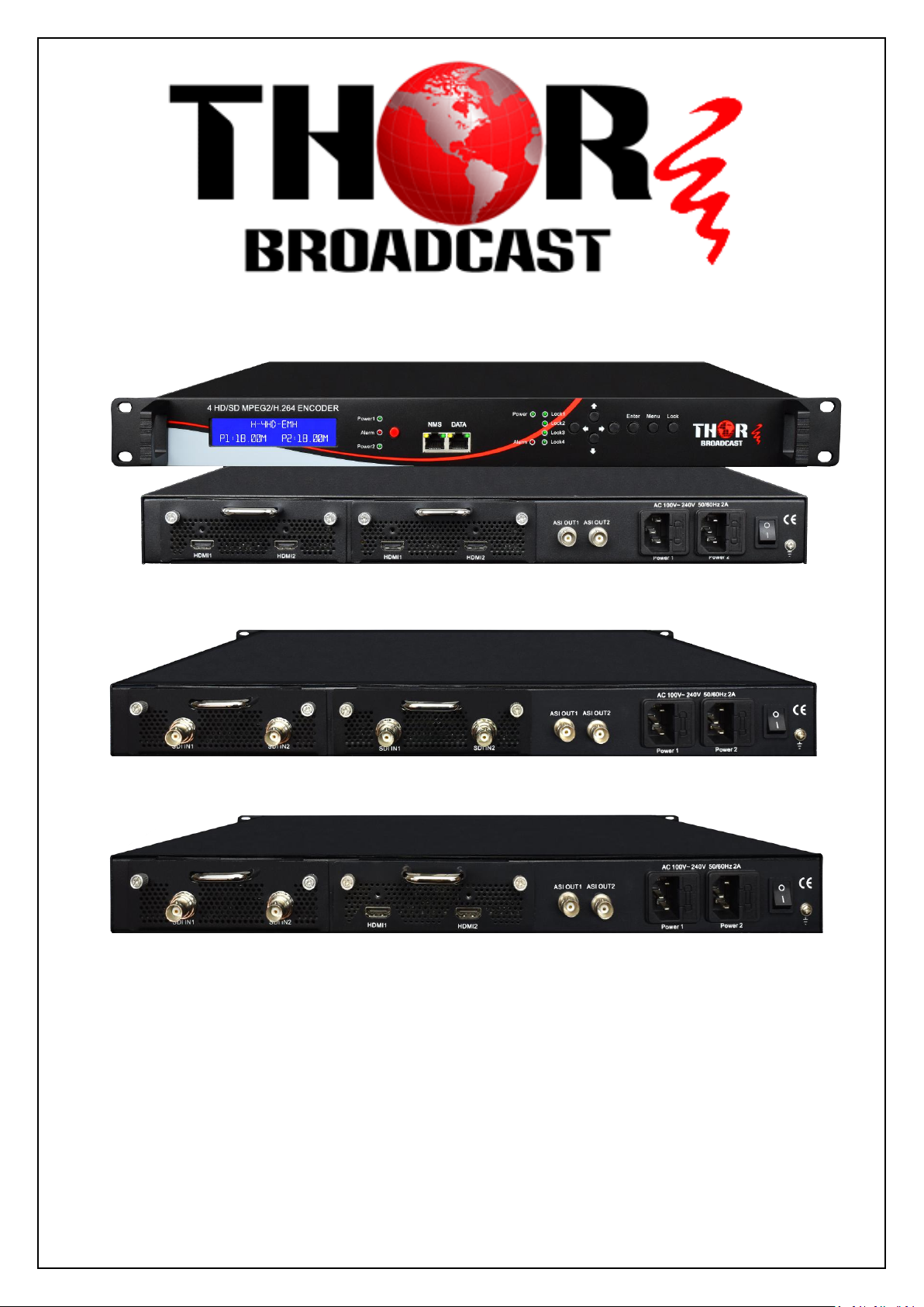
H-4HD-EMH
H-4HD-EMS
H-4HD-EMHS
4 Channel SDI & HDMI
Pro-DVB Contribution Encoder
For ASI and IPTV
User Manual 2017
Page 2

H-4HD-EMS & EMH
A Note from Thor Broadcast about this
Manual
Intended Audience
This user manual has been written to help people who have to use, integrate and to install
the product. Some chapters require some prerequisite knowledge in electronics and
especially in broadcast technologies and standards.
Disclaimer
No part of this document may be reproduced in any form without the written permission of
Thor Broadcast.
The contents of this document are subject to revision without notice due to continued
progress in methodology, design and manufacturing. Thor shall have no liability for any
error or damage of any kind resulting from the use of this document.
Copy Warning
This document includes some confidential information. Its usage is limited to the owners
of the product that it is relevant to. It cannot be copied, modified, or translated in another
language without prior written authorization from Thor Broadcast.
Thor Fiber 2017 Tel: (800) 521-8467 Email: [email protected] www.thorbroadcast.com
Page 3

H-4HD-EMS & EMH
Table of Contents
CHAPTER 1 INTRODUCTION .................................................................................................................... 4
1.1 PRODUCT OVERVIEW .............................................................................................................................. 4
1.2 KEY FEATURES ........................................................................................................................................ 4
1.3 SPECIFICATIONS ...................................................................................................................................... 5
1.4 PRINCIPLE CHART ................................................................................................................................... 6
1.5 APPEARANCE AND DESCRIPTION ............................................................................................................. 6
CHAPTER 2 INSTALLATION GUIDE ........................................................................................................... 8
2.1 GENERAL PRECAUTIONS ......................................................................................................................... 8
2.2 POWER PRECAUTIONS ............................................................................................................................. 8
2.3 DEVICE’S INSTALLATION FLOW CHART ILLUSTRATED AS FOLLOWING .................................................... 8
2.4 ENVIRONMENT REQUIREMENT ................................................................................................................ 9
2.5 GROUNDING REQUIREMENT .................................................................................................................... 9
CHAPTER 3 OPERATION ........................................................................................................................ 11
3.1 LCD MENU CLASS TREE ...................................................................................................................... 11
3.2 INITIAL STATUS ..................................................................................................................................... 12
3.3 GENERAL SETTINGS FOR MAIN MENU .................................................................................................. 12
CHAPTER 4 WEB NMS OPERATION ....................................................................................................... 20
4.1 LOGIN .................................................................................................................................................... 20
4.2 OPERATION ........................................................................................................................................... 21
CHAPTER 5 TROUBLESHOOTING ........................................................................................................... 30
CHAPTER 6 PACKING LIST ..................................................................................................................... 31
Thor Fiber 2017 Tel: (800) 521-8467 Email: [email protected] www.thorbroadcast.com
Page 4

H-4HD-EMS & EMH
Chapter 1 Introduction
1.1 Product Overview
The Thor Broadcast series SDI and HDMI Pro-DVB 4 channel input encoders are
designed for modern state of the art broadcasts for ASI and IP solutions. Managed
through any modern web browser, each encoder can be independently adjusted for
bitrate, codecs, and video image qualities. Encoding support for the MPEG-2, or
H.264, codec along with Dolby AC/3 audio ensure that the programs generated by this
encoder can be used around the world on a global scale. All four program streams are
multiplexed into an ASI MPTS output on mirrored BNC terminals. The 4 encoded
HDMI (HD-SDI) programs will output through ASI and IP ports in MPTS or SPTS.
This powerful design allows you to distribute up to 1080p program streams in crystal
clear High Definition. This design is topped off with a dual power supply to ensure
that your Thor Broadcast encoder has the redundancy needed for any application.
1.2 Key Features
Dual power supply
MPEG2 HD/SD & MPEG4 AVC/H.264 HD/SD video encoding
MPEG1 Audio Layer 2, LC-AAC, HE-AAC and AC3 audio encoding
4*HDMI or 4*SDI inputs (model dependent)
Supports CC(close caption) only for SDI interface EIA 708
VBR/CBR rate control mode
Low Latency, best in class of any modern encoder
PSI/SI editing and inserting
IP null packet filter
ASI output, IP (MPTS & 4 SPTS) output over UDP, RTP
LCD display, Remote control and firmware
Web-based NMS management; Updates via web
Thor Fiber 2017 Tel: (800) 521-8467 Email: [email protected] www.thorbroadcast.com
Page 5

H-4HD-EMS & EMH
Encoding
MPEG2 & MPEG4 AVC/H.264
Input
HDMI*4/SDI*4
Resolution
1920*1080_60P, 1920*1080_50P, (-for MPEG4 AVC/H.264 only)
1920*1080_60i, 1920*1080_50i,
1280*720_60p, 1280*720_50P
720*480_60i, 720*576_50i
Bit Rate
0.5~19.5Mbps for H.264 encoding
1~19.5Mbps for MPEG-2 encoding
Rate Control Mode
CBR/VBR
encoding
MPEG1 Layer II, MPEG2-AAC, MPEG4-AAC, Dolby Digital AC3
Sample rate
48KHz
Bit rate
64kbps, 96kbps,128kbps, 192kbps, 256kbps, 320kbps
Local interface
LCD + control buttons
Remote management
Web NMS
Low Latency Mode
Normal, mode 1, mode 2
output
2*ASI out (BNC type);
IP (1 MPTS & 4 SPTS) over UDP, RTP (RJ45, 100M)
NMS interface
RJ45, 100M
Language
English
Power supply
AC 100V~240V
Power Consumption
45W
Dimensions
482*400*44mm
Weight
4.5 kgs
Operation temperature
0~45℃
1.3 Specifications
Encoding Section
Video
Audio
System
General
Thor Fiber 2017 Tel: (800) 521-8467 Email: [email protected] www.thorbroadcast.com
Page 6
H-4HD-EMS & EMH
ASI Output
MPEG-2 or H.264 HD/SD
Encoding
HDMI/SDI
HDMI/SDI
MPEG-2 or H.264 HD/SD
Encoding
MPEG-2 or H.264 HD/SD
Encoding
MPEG-2 or H.264 HD/SD
Encoding
IP Output
HDMI/SDI
HDMI/SDI
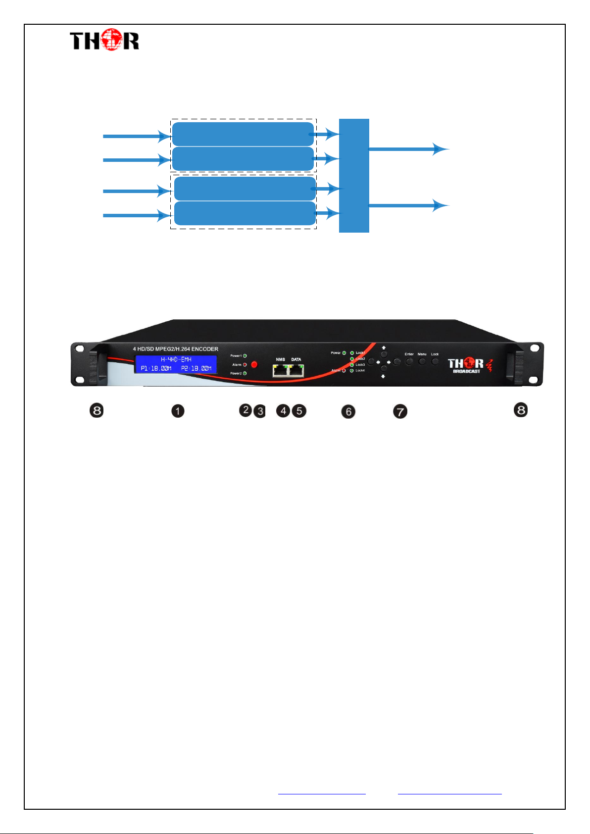
1.4 Principle Chart
1.5 Appearance and Description
Front Panel Illustration
① LCD window
② Power supply indicators
③ Power Alarm Switch: When only one power supply is connected or one of the power
supplies fails, the device will give alarm sound, and then press the alarm switch to turn off
the alarm sound.
④ NMS port for the connection between the device and PC
⑤ DATA port for IP signal out
⑥ Indicators for whole unit power supply, working alarm and input signal lock status
⑦ Control Buttons
⑧ Handles
Thor Fiber 2017 Tel: (800) 521-8467 Email: [email protected] www.thorbroadcast.com
Page 7
H-4HD-EMS & EMH
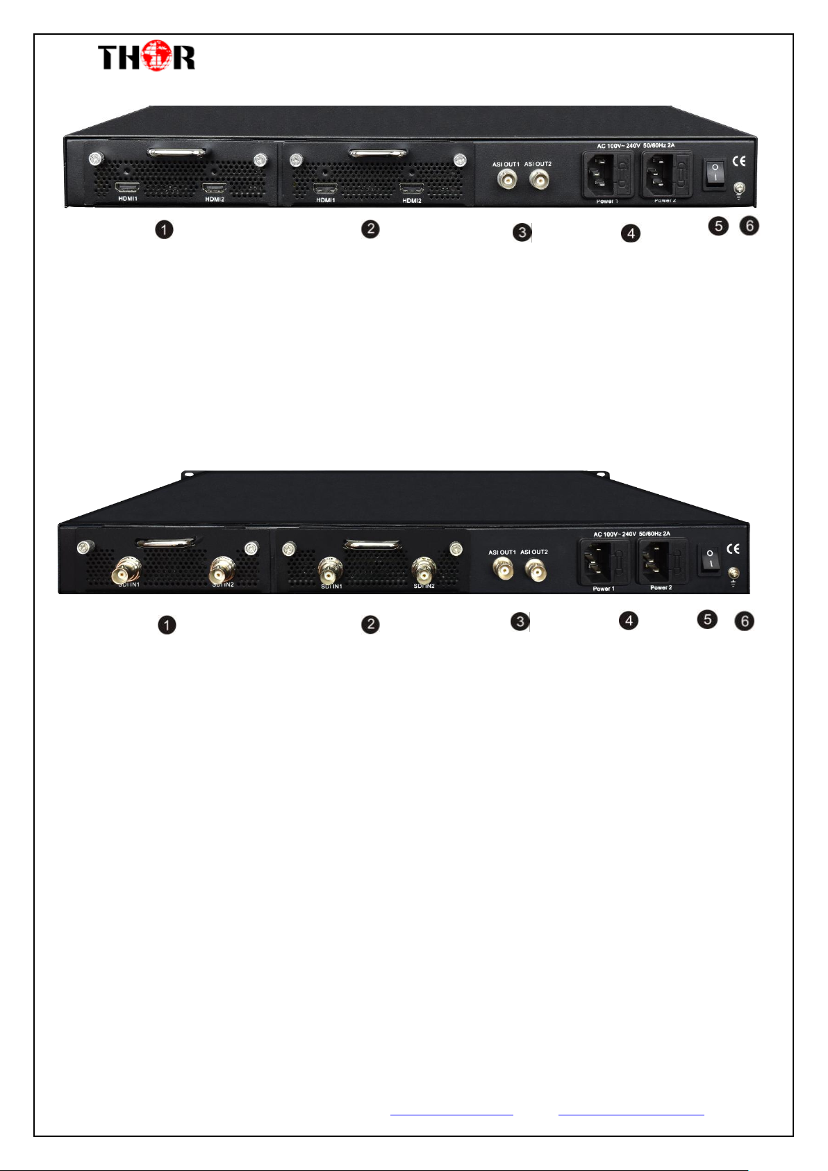
Rear Panel -- H-4HD-EMH
① HDMI Input Module 1: Program input port 1&2
② HDMI Input Module 2: Program input port 3&4
③ ASI output ports
④ Power Supply Slot
⑤ Power Switch
⑥ Grounding
Rear Panel -- H-4HD-EMS
① SDI Input Module 1: Program input port 1&2
② SDI Input Module 2: Program input port 3&4
③ ASI output ports
④ Power Supply Slot
⑤ Power Switch
⑥ Grounding
Thor Fiber 2017 Tel: (800) 521-8467 Email: [email protected] www.thorbroadcast.com
Page 8

H-4HD-EMS & EMH
Connecting
Grouding
Wire and
Power
Cord
Acquisition
Check
Installing
Device
Setting
Parameter
Running
Device
Connecting
Signal
cable
Chapter 2 Installation Guide
Please use caution when operating this device in order to abstain any possible injury during installation.
For this reason, please read all details listed below and make and use caution before proceeding to
operate and use this electronic equipment.
2.1 General Precautions
Must be operated and maintained free of dust or debris.
The cover should be securely fastened, do not open the cover of the products when the power
is on.
After installation, securely stow away all loose cables, external antenna, and others.
2.2 Power Precautions
When you connect the power source, make sure it is grounded correctly so it doesn’t cause an
overload.
Avoid operating on a wet floor in the open. Make sure the extension cable is in good
condition.
Make sure the power switch is off before you start to install the device.
2.3 Device’s Installation Flow Chart Illustrated as following
Thor Fiber 2017 Tel: (800) 521-8467 Email: [email protected] www.thorbroadcast.com
Page 9

H-4HD-EMS & EMH
Item
Requirement
Machine Hall
Space
When user installs machine frame array in one machine hall,
the distance between 2 rows of machine frames should be
1.2~1.5m and the distance against wall should be no less than
0.8m.
Machine Hall Floor
Electric Isolation, Dust Free
Volume resistivity of ground anti-static material:
1X10⁷~1X10¹⁰,Grounding current limiting resistance: 1M
(Floor bearing should be greater than 450Kg/㎡)
Environment
Temperature
5~40℃(sustainable ),0~45℃(short time),
installing air-conditioning is recommended
Relative Humidity
20%~80% sustainable 10%~90% short time
Pressure
86~105KPa
Door & Window
Installing rubber strip for sealing door-gaps and dual level
glasses for window
Wall
It can be covered with wallpaper, or brightness less paint.
Fire Protection
Fire alarm system and extinguisher
Power
Requiring device power, air-conditioning power and lighting
power are independent to each other. Device power requires
AC 110V±10%, 50/60Hz or AC 220V±10%, 50/60Hz. Please
carefully check before running.
2.4 Environment Requirement
2.5 Grounding Requirement
It is important to keep this device grounded to ensure all of the modules
function correctly. Correctly grounding the device will also help prevent any
Thor Fiber 2017 Tel: (800) 521-8467 Email: [email protected] www.thorbroadcast.com
Page 10

H-4HD-EMS & EMH
electrical interference, lightening. Etc. Also it helps reject minor interference that
may disrupt the devices ability to function smoothly. General rule of them, make
sure the device is grounded when installing anywhere.
Always use copper wire. When applied correctly the ground must be wrapped
well to ensure maximum conduction so it can reduce any high frequencies. The
copper ground wire should also be as short and thick as possible
Installer must make sure that the two ends of the ground are well conducted
and have appropriate anti-rust properties.
It is prohibited to use any other device as part of the grounding electric
circuit.
The area of the conduction between the ground wire and device’s frame
should be no less than 25 ㎡.
Thor Fiber 2017 Tel: (800) 521-8467 Email: [email protected] www.thorbroadcast.com
Page 11
Initializing
General Working Status
1 Status
2 Input Sets
3.1 TSID
3.2 ONID
3.3 Output Bitrate
3.4 NIT Insert
3.5 SDT Insert EX
Low Delay
2.1 Input 1
2.2 Input 2
Video Format
Video Bitrate
Audio Format
Audio Bitrate
2.1.1 Program 1
(Same content with 2.1.1)
2.1.2 Program 2
2.2.1 Program 1
2.2.2 Program 2
(Same content with 2.1.1)
(Same content with 2.1.1)
3 TS Config
1.1 Uptime
Video
Audio
Program Info
Video in status
Service Provider
Program name
Service ID
PCR PID
Video PID
Program output enable
PMT PID
Audio PID
4 Network
4.1 NMS
4.2 IP Stream
4.1.1 NMS IP
4.1.2 Subnet mask
4.1.3 Gateway
4.1.4 MAC Address
4.1.5 Web NMS Port
4.1.6 Reset Password
4.2.1 MPTS Output
4.2.2 SPTS A
4.2.3 SPTS B
4.2.4 SPTS C
4.2.5 SPTS D
Output IP
Null PKT Filter
Output Port
Subnet Mask
Gateway
Data Enable
Service IP
Protocol
(Same content with 4.2.1)
(Same content with 4.2.1)
(Same content with 4.2.1)
(Same content with 4.2.1)
5.1 Save Config
5.2 Load Saved
5.3 Factory Reset
5.4 LCD time-out
5.5 Version
5 System
Dialog normal
3.6 PMT Insert EX
3.7 VCT Mode
3.8 SDT Insert EX
H-4HD-EMS & EMH
Chapter 3 Operation
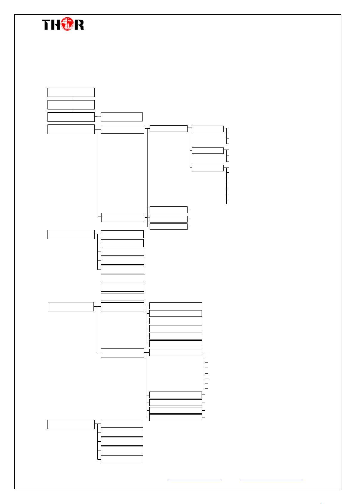
3.1 LCD Menu Class Tree
Thor Fiber 2017 Tel: (800) 521-8467 Email: [email protected] www.thorbroadcast.com
Page 12
H-4HD-EMS & EMH
Start up…
Start OK…
HD Encoder
P1:X.XXMbps P2: X.XXMbps
3 TS Config
4 Network
5 System
1 Status
2 Input Sets
1.1 Uptime
Uptime
0 Day(s) xx-xx-xx
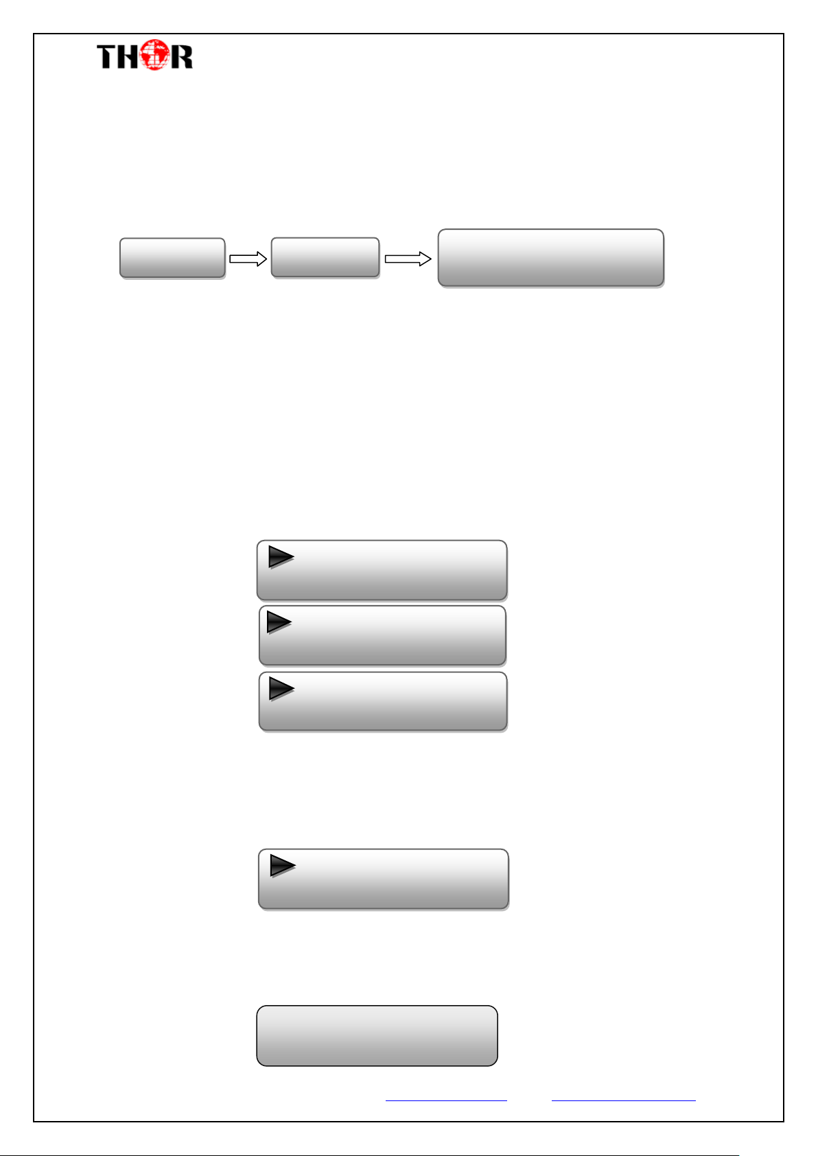
3.2 Initial Status
Switch on the device and after a few seconds’ initialization, it presents start-up pictures as
below:
HD Encoder: H-4HD-EMH or H-4HD-EMS
P1: Program 1; P2: Program 2; P3: Program 3; P4: Program 4
X.XX Mbps: indicates the current encoding bit rate of the corresponding channel.
3.3 General Settings for Main Menu
Press LOCK key on the front panel to enter the main menu. The LCD will display the
following pages where you can configure the parameters for the Thor Encoder.
Press UP/DOWN buttons to specify one item and then press ENTER to go inside its
submenus. Press MENU to step back to upper level menu.
1) Status
Uptime
Displays the working time duration of the device. It times upon power on.
Thor Fiber 2017 Tel: (800) 521-8467 Email: [email protected] www.thorbroadcast.com
Page 13
H-4HD-EMS & EMH
2.1 Input 1
2.2 Input 2
2.1.1 Program 1
2.1.2 Program 2
Program Info
Program output
Program name
Service Provider
Service ID
PMT PID
PCR PID
Video PID
Audio PID
Video
Video in status
Video Format
Low Delay
Video Bit Rate
Audio
Audio Format
Dialog normal
Audio Bit rate
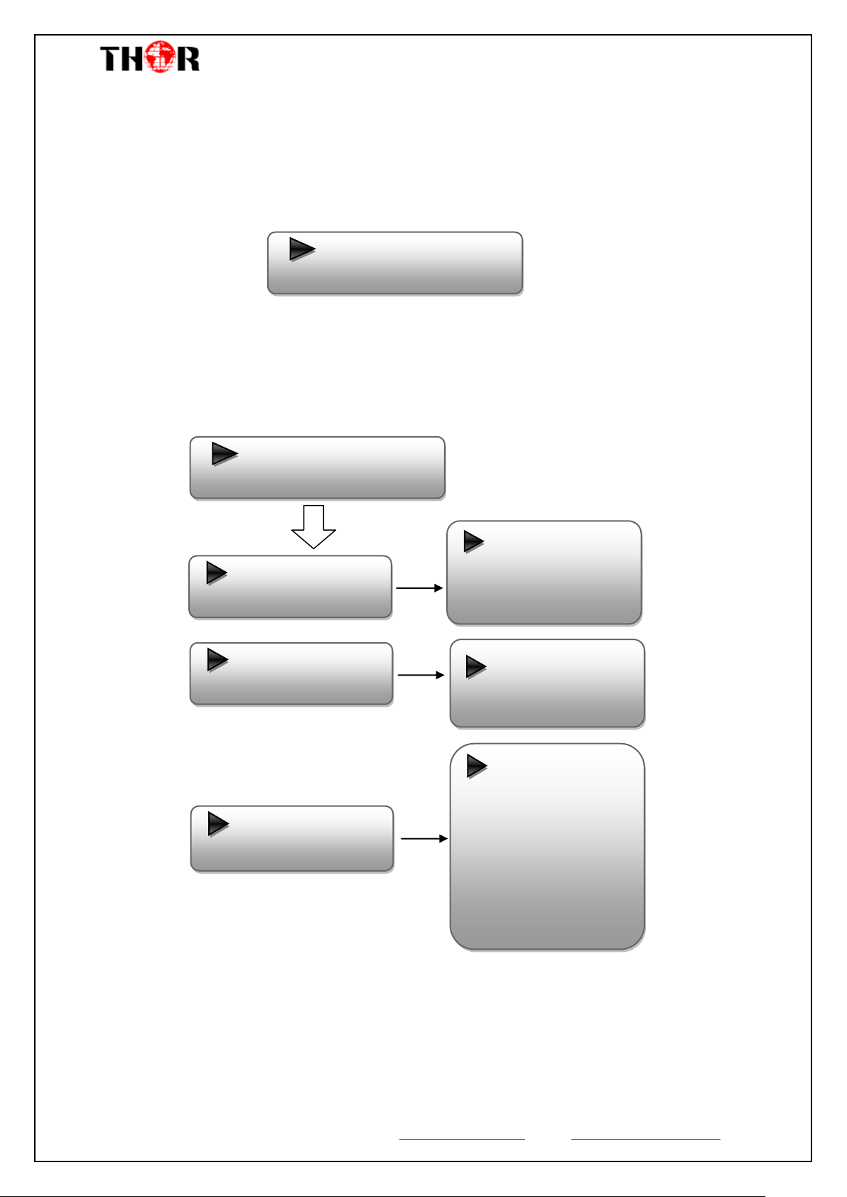
2) Input Sets
Under this submenu, the LCD will show “2.1 Input 1” and “2.2 Input 2” to represent
the two HDMI/SDI input modules respectively.
Each HDMI/SDI input module support two program input connecters. Under
submenus 2.1 (or 2.2), you could set the video/audio parameters for the 2 HDMI
programs respectively.
Video in Status
Enter this menu to check the video input status.
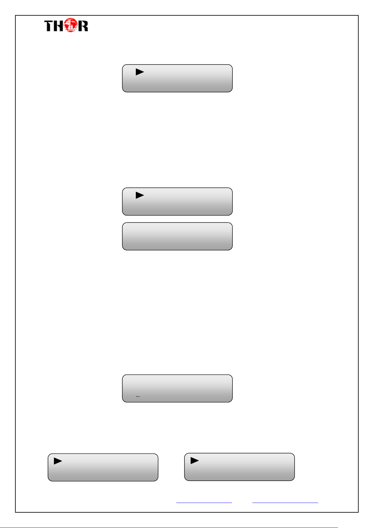
Video Format
The HDMI & SDI encoders support both “MPEG2” and “H.264” video encoding
Thor Fiber 2017 Tel: (800) 521-8467 Email: [email protected] www.thorbroadcast.com
Page 14
H-4HD-EMS & EMH
MPEG2
H.264
Normal
Mode 1
Video Bit Rate
14.000 Mbps
MPEG1 Layer 2
MPEG2 AAC
MPEG4 AAC
AC3
Mode 2
formats. Enter this menu to select one format from the 2 options.
Press ENTER to shift ‘*’ to ‘►’, and then press UP/DOWN buttons to specify one
item and then press ENTER to confirm. Press MENU to step back to upper level menu.
(The operation method is applicable for this entire manual.)
Low Delay
Thor Broadcast Encoders offer Low Latency options (MODE 1 is the Fastest)
…..………………………………..... NOTE ……..……..………………………….
The different combination of Video Format, Video Bit-rate, Low Delay Mode, the
Resolution of signal source and Decoding options all have an effect on Latency.
…………………………………………………………………………………………..……
Video Bit Rate
Set the video encoding bit rate manually in this menu.
0.5~19.5Mbps for H.264 encoding
1~19.5Mbps for MPEG-2 encoding
Audio Format
The HDMI encoder supports 4 encoding formats. Enter this menu to select one format
from the 4 options.
Thor Fiber 2017 Tel: (800) 521-8467 Email: [email protected] www.thorbroadcast.com
Page 15
H-4HD-EMS & EMH
Audio Bitrate
64Kbps
Program Output
Enable
Program Name
TV-101
Service Provider
TV-Provider
Service ID
0x201
PMT PID
0x200
PCR PID
0x203
Video PID
0x201
Audio PID
0x202
Dialog Normal
-31dB
Dialog Normal
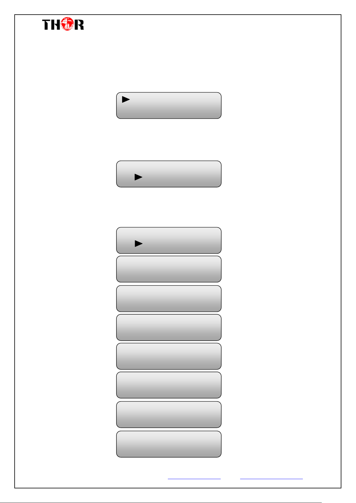
Enter this menu to set the dialog normal (Range -31~-1dB)
Audio Bit Rate
The audio bit rate ranges from 64Kbps to 320Kbps. Select one bit-rate from the
options provided.
Program Info
Enable or disable the program output in the first sub-menu and configure the other
parameters in the rest sub-menus.
Thor Fiber 2017 Tel: (800) 521-8467 Email: [email protected] www.thorbroadcast.com
Page 16
H-4HD-EMS & EMH
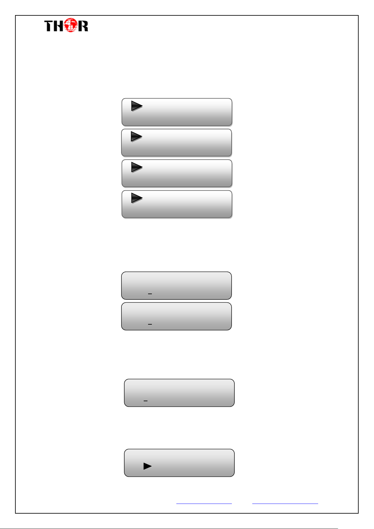
3.1 TS ID
3.2 ON ID
3.3 Output Bit rate
3.4 NIT Insert
3.5 SDT Insert EX
3.6 PMT Insert EX
TS ID
0x0001
ON ID
0x0001
Output Bit rate
60.000 Mbps
NIT Insert
Yes No
3.7 VCT Mode
3.8 ASI output
3) TS Config
This encoder support TS output via ASI ports. ‘TS Config’ is for the configuration of
ASI output. Its submenus contain:
TS ID/ON ID
Set the TS ID and Original Network ID in the 2 submenus. The IDs are in hexadecimal
form.
Output Bit rate
Set the max output bit rate for the ASI MPTS out. (Range 0-100 Mbps)
NIT Insert
Insert your NIT with operations in the menu.
Thor Fiber 2017 Tel: (800) 521-8467 Email: [email protected] www.thorbroadcast.com
Page 17
H-4HD-EMS & EMH
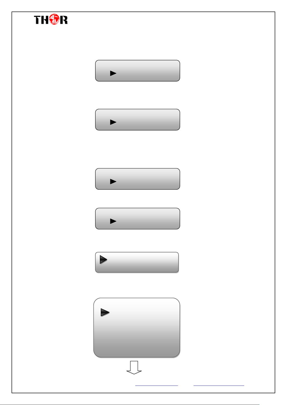
4.1 NMS
4.2 IP Stream
ASI Output
MPTS
NMS
4.1.1 NMS IP
4.1.2 Subnet Mask
4.1.3 Gateway
4.1.4 MAC Address
4.1.5 Web NMS Port
4.1.6 Reset Password
SDT Insert Ex
Yes No
PMT Insert Ex
Yes No
VCT Mode
TVCT
SDT Insert External
Enable SDT with operations in the menu.
PMT Insert External
Enable PMT with operations in the menu.
VCT Mode
Set VCT Mode with operations in the menu, there are three options: TVCT, CVCT,
close VCT.
ASI Output
Copy a stream from the IP out streams (1 MPTS & 8 SPTS) to output through ASI.
4) Network
‘Network’ is divided into 2 parts: NMS and IP Stream.
NMS
Submenus under ‘NMS’ are for setting the parameters related to the device connection
in the network.
Thor Fiber 2017 Tel: (800) 521-8467 Email: [email protected] www.thorbroadcast.com
Page 18
H-4HD-EMS & EMH
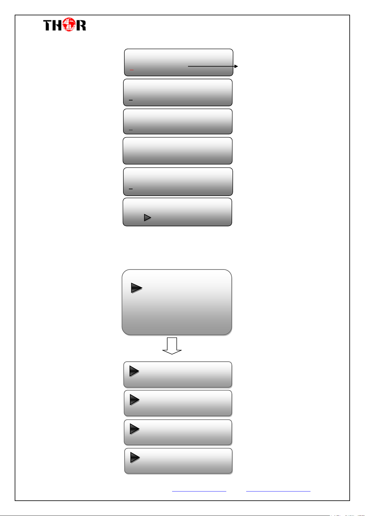
Data Enable
Null PKT Filter
Output IP
Output Port
Service IP
Subnet Mask
NMS IP
192.168.000.136
Subnet Mask
255.255.255.000
Gateway
192.168.000.001
MAC Address
201012345678
Reset Password?
Yes NO
Web NMS Port
00080
The IP address for connecting
the device to PC
IP Stream
4.2.1 MPTS Output
4.2.2 SPTS Output A
4.2.3 SPTS Output B
4.2.4 SPTS Output C
4.2.5 SPTS Output D
Gateway
Protocol
IP Stream
Submenus under ‘IP Stream’ are for setting the output IP stream in MPTS or SPTS.
Thor Fiber 2017 Tel: (800) 521-8467 Email: [email protected] www.thorbroadcast.com
Page 19
H-4HD-EMS & EMH
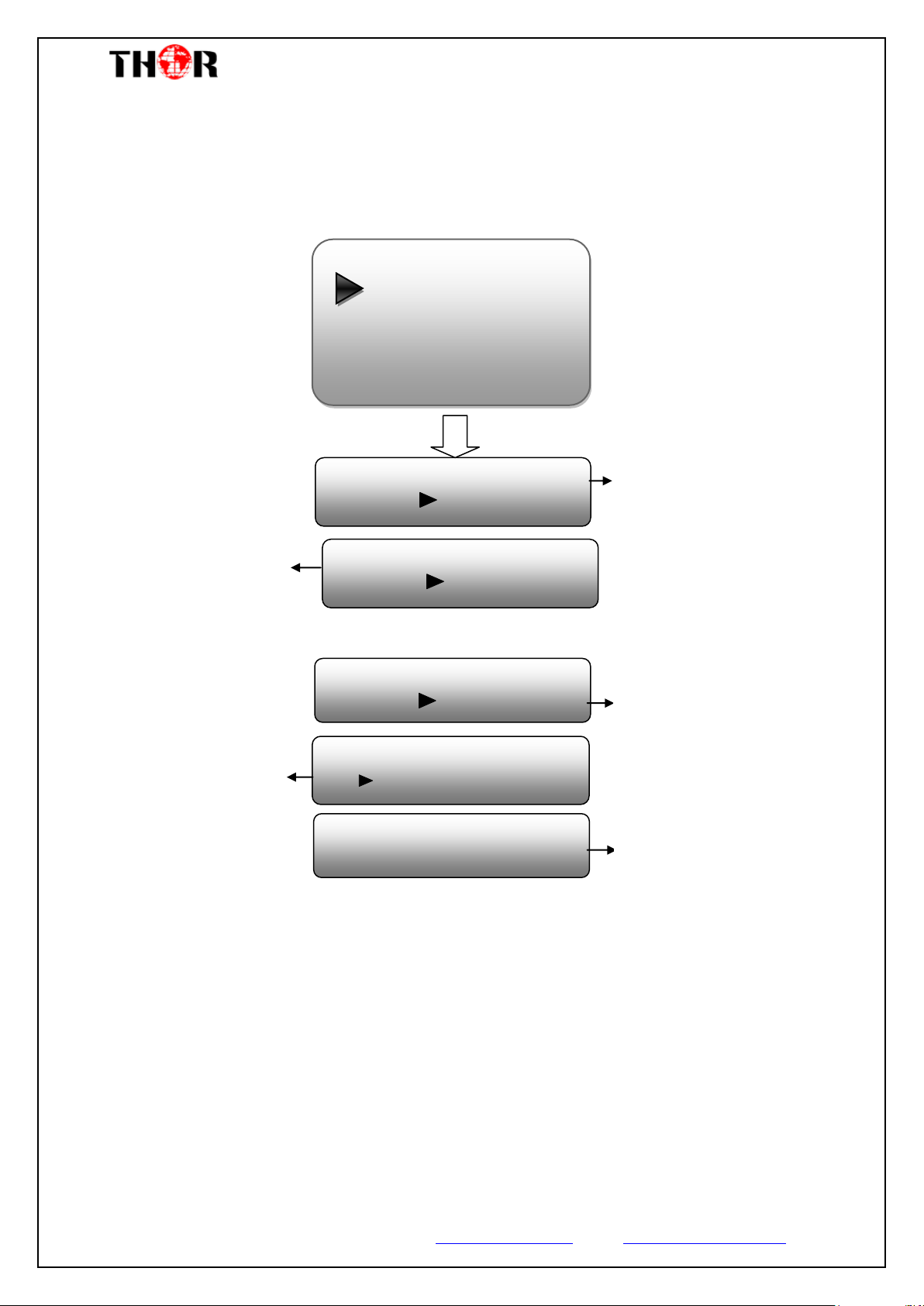
Save Configuration?
Yes No
Load Saved CFG?
Yes No
Reset All Sets?
Yes No
LCD Time-out
30 s
H-4HD-EMS HD Encoder
SW x.xx HW x.xx
Choose yes to save settings.
Press ENTER to confirm
Choose yes to restore the
device into the last saved
configuration.
Choose yes to restore the
device into factory’s default
configuration.
Press DOWN/UP key to select
a time out for the LCD lighting
duration (5-120 seconds)
It displays the device name
and software/hardware
version information.
System
5.1 Save Config
5.2 Load Saved CFG
5.3 Factory Reset
5.4 LCD Time-out
5.5Version
5) System
Set the system parameters in this menu. Enter ‘System’ submenus to separately set
corresponding parameters.
Thor Fiber 2017 Tel: (800) 521-8467 Email: [email protected] www.thorbroadcast.com
Page 20
H-4HD-EMS & EMH
Chapter 4 WEB NMS Operation
For setting configurations you can use the front panel; also you are able to control and set
the configurations on any computer by connecting the device to the web NMS Port. You
should ensure that the computer’s IP address is different from the Thor Encoders IP address;
otherwise, it would cause IP conflict.
4.1 login
The default IP of this device is 192.168.0.136. We can modify the IP through the front
panel. Connect the pc and the device with net cable, and use ping command to confirm
they are on the same network segment. E.G. the PC IP address is 192.168.99.252, we
then change the device IP to 192.168.99.xxx (xxx can be 0 to 255 except 252 to avoid
IP conflict). Use any web browser to connect the device with the PC by inputting the
Encoder & Modulator’s IP address in the browser’s address bar and press Enter. It will
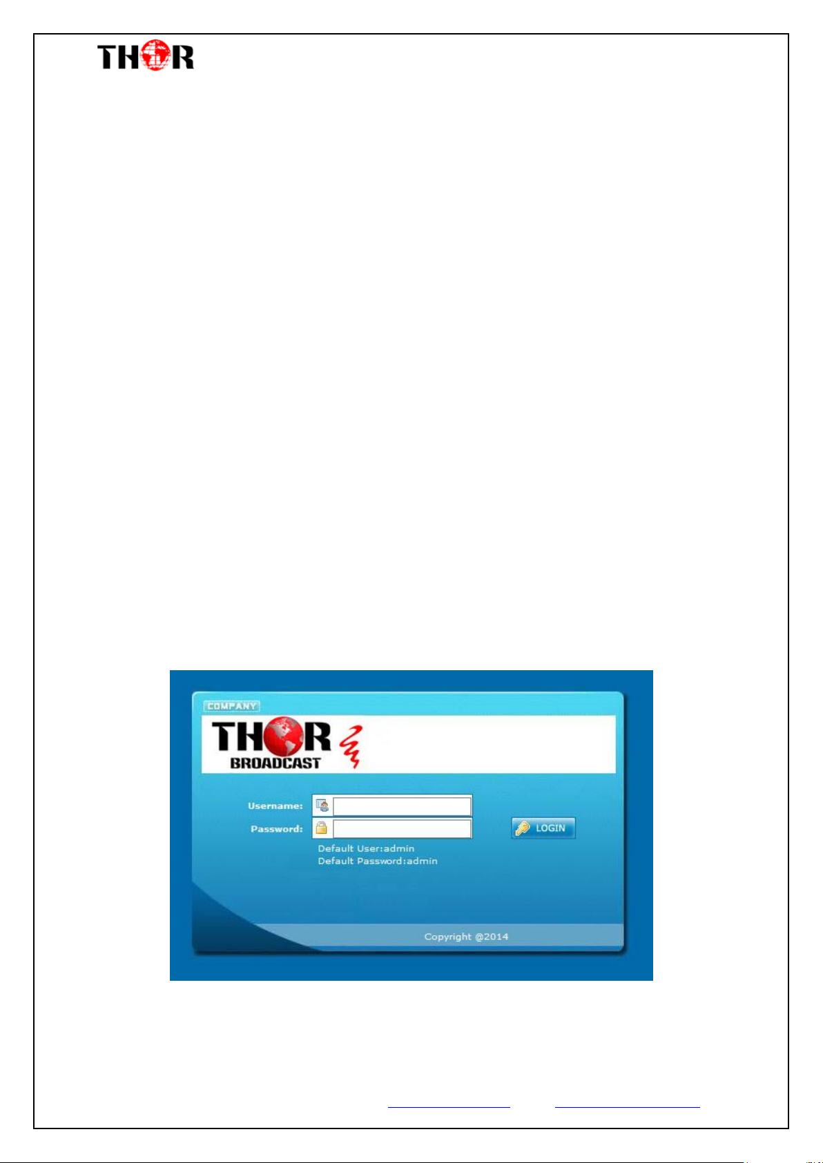
display the Login interface as Figure-1. Input the Username and Password (Both the
default Username and Password are “admin”.) and then click “LOGIN”
Figure-1
Thor Fiber 2017 Tel: (800) 521-8467 Email: [email protected] www.thorbroadcast.com
Page 21
H-4HD-EMS & EMH
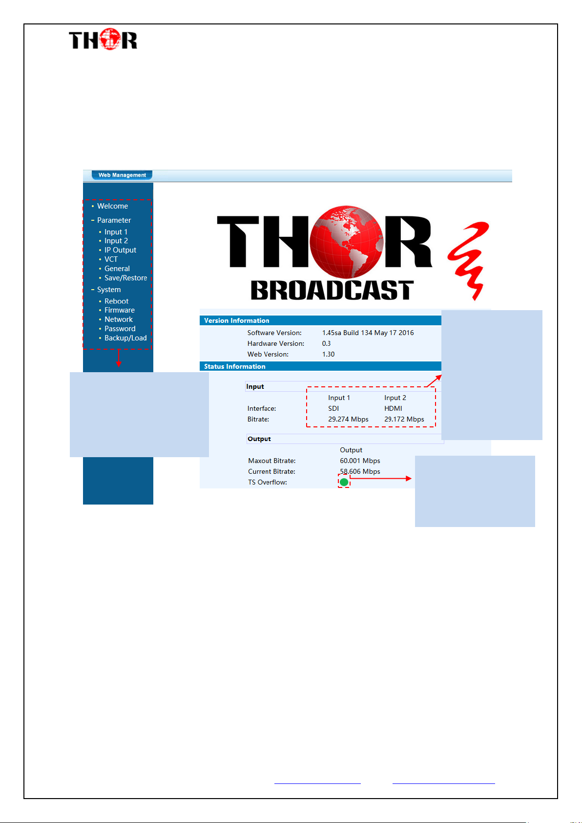
TS indicators—Green
light indicates the TS is
normal, otherwise turns
to red if there are errors.
It automatically
identifies and
displays the signal
source interface and
real-time encoding
bit rate of
corresponding input
channel.
User can click any item
here to enter the
corresponding interface to
check information or set the
parameters.
4.2 Operation
When we confirm the login, it displays the WELCOME interface.
In the following sections we are using a 4-channel unit with 2 SDI inputs and 2 HDMI
inputs to demonstrate its GUI menus.
Input 1
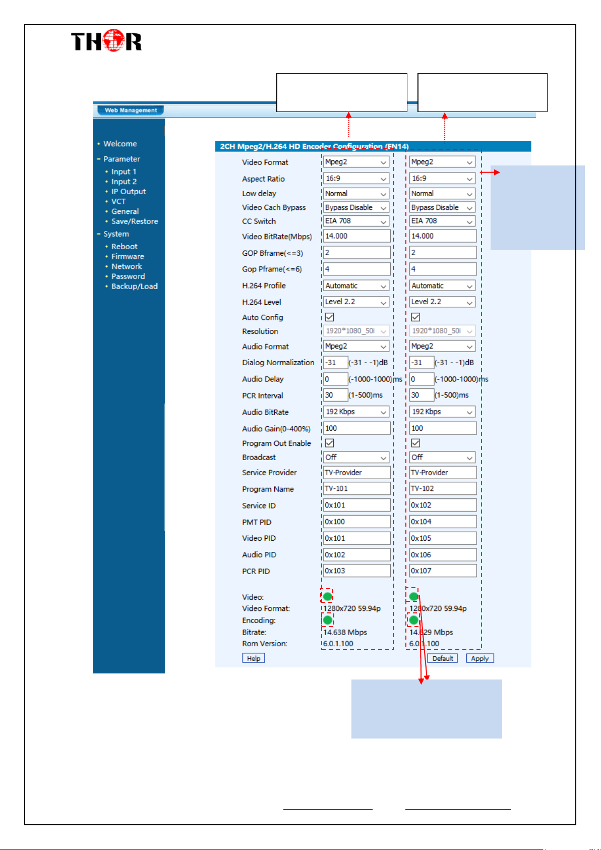
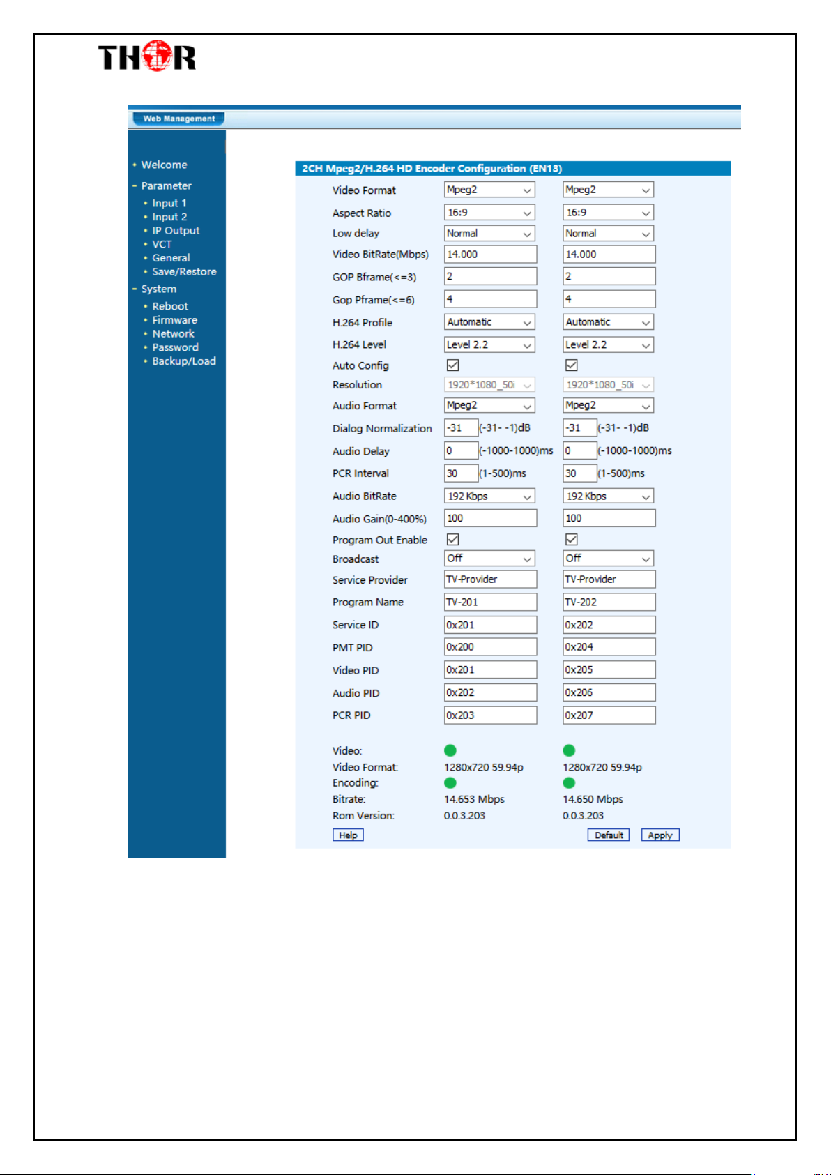
From the menu on left side of the webpage, clicking “Input 1”, displays the
information of the programs (1st & 2nd) from the SDI inputs.
Thor Fiber 2017 Tel: (800) 521-8467 Email: [email protected] www.thorbroadcast.com
Figure-2
Page 22
H-4HD-EMS & EMH
This column is for setting
the 1st HD-SDI input.
This column is for setting
the 2ed HDSDI input
General Settings
for the HDMI IN
programs: User
can edit any item
listed as needed.
Encoding Status—Green light
indicates its encoding
normally, otherwise turns red.
Thor Fiber 2017 Tel: (800) 521-8467 Email: [email protected] www.thorbroadcast.com
Figure-3
Page 23
H-4HD-EMS & EMH
…..………………………………..... NOTE ……..……..………………………….
The different combination of Video Format, Video Bit-rate, Low Delay Mode
and the Resolution of signal source will have an impact on the latency. Please
refer to the Appendix attached for detailed information.
…………………………………………………………………………………………..……
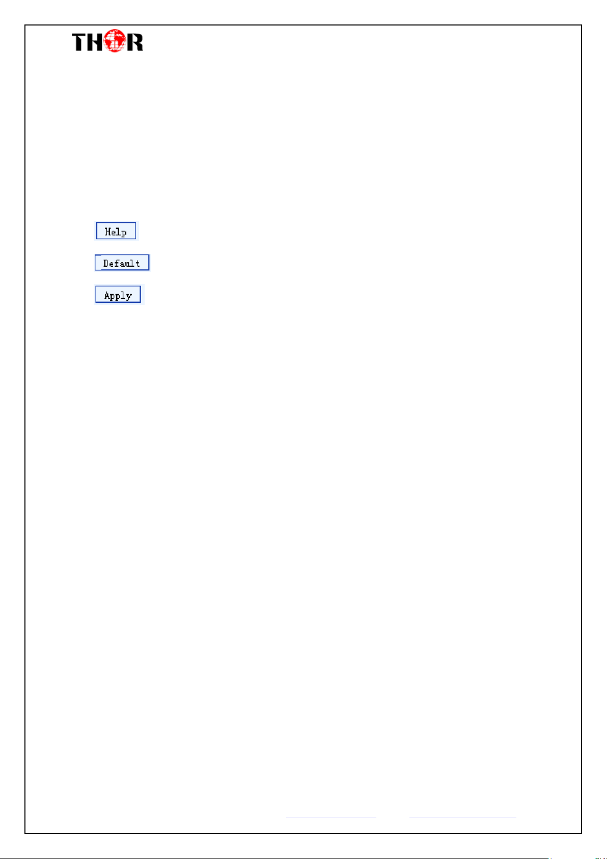
For user to turn to refer detailed explanation of terms on this interface
Click this button to apply the default setting of Input 1
Click this button to apply the modified parameters.
Input 2
Similarly, from the menu on left side of the webpage, clicking “Input 2”, displays the
information of the programs (3rd & 4th inputs) from the HDMI encoding module.
Thor Fiber 2017 Tel: (800) 521-8467 Email: [email protected] www.thorbroadcast.com
Page 24
H-4HD-EMS & EMH
IP Output
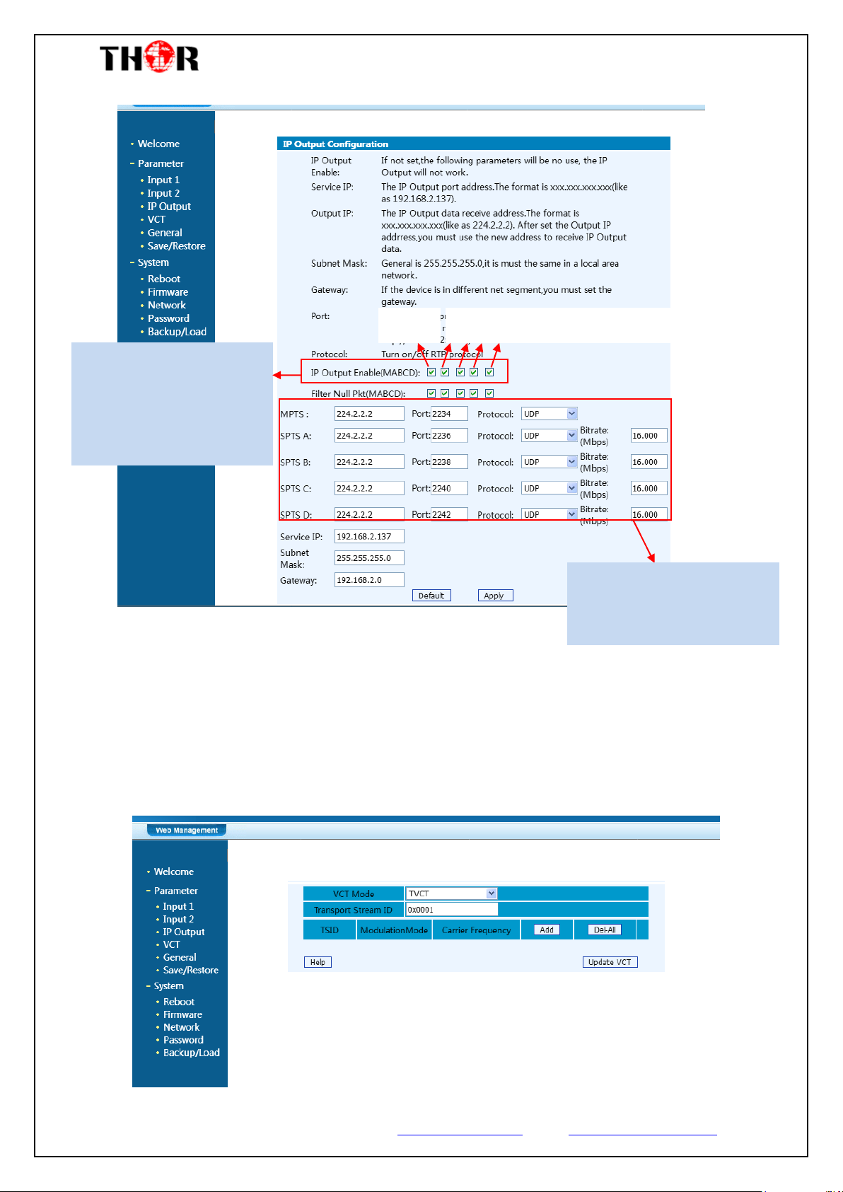
Click “IP Output”, it will display the interface where to configure the output IP stream
in MPTS or SPTS that will output on a single RJ45 port.
Thor Fiber 2017 Tel: (800) 521-8467 Email: [email protected] www.thorbroadcast.com
Page 25
H-4HD-EMS & EMH
MPTS
4 SPTS for the 4 programs respectively
Supports 1 MPTS & 4 SPTS IP
outputs. Click the related box
to enable the corresponding
program to output through IP
Channels.
Configures the output IP
address and ports for the IP
Channels respectively.
Figure-5
After setting the parameters, click “Apply” to save.
VCT
Click “VCT” from the menu, it will display the interface as Figure-6 where to set the
VCT configuration.
Thor Fiber 2017 Tel: (800) 521-8467 Email: [email protected] www.thorbroadcast.com
Figure-6
Page 26
H-4HD-EMS & EMH
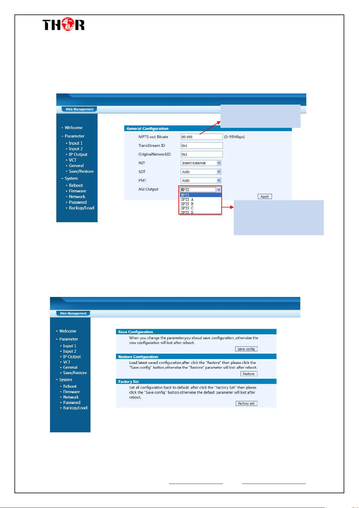
To set the max output bit
rate for the ASI MPTS out
Users can copy a stream from
the IP out streams (1 MPTS & 4
SPTS) to output through ASI.
General
Clicking “General” from the menu, it will display the interface as Figure-7 where to
set the network info for the output TS.
Figure-7
Save/Restore
From the menu on left side of the webpage, clicking “Save/Restore”, it will display the
screen as Figure-8 where to save or restore your configurations.
Thor Fiber 2017 Tel: (800) 521-8467 Email: [email protected] www.thorbroadcast.com
Figure-8
Page 27
H-4HD-EMS & EMH
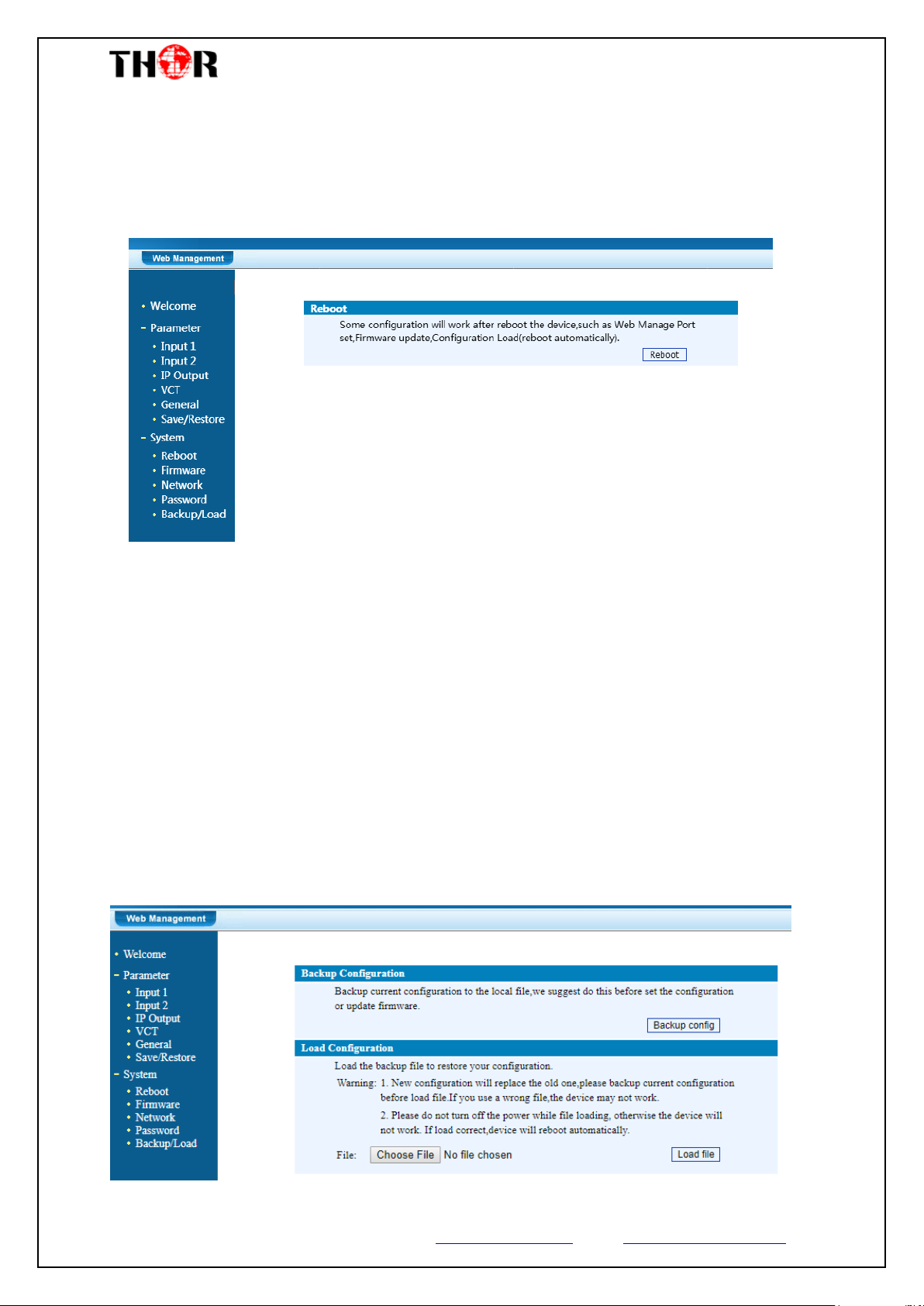
Restart the Device
Click “Reboot” from the menu, the screen will display as Figure-9. Here when
clicking “Reboot” box, it will restart the device automatically.
Figure-9
Update the Device
Click “Firmware” from the menu it will display the screen as Figure-10. Here user
can update the device by using the update file.
Click “Browse” to find the path of the device update file for this device then click
“Update” to update the device.
After updating the device, user needs to restart the device by using Reboot option.
Figure-10
Thor Fiber 2017 Tel: (800) 521-8467 Email: [email protected] www.thorbroadcast.com
Page 28
H-4HD-EMS & EMH
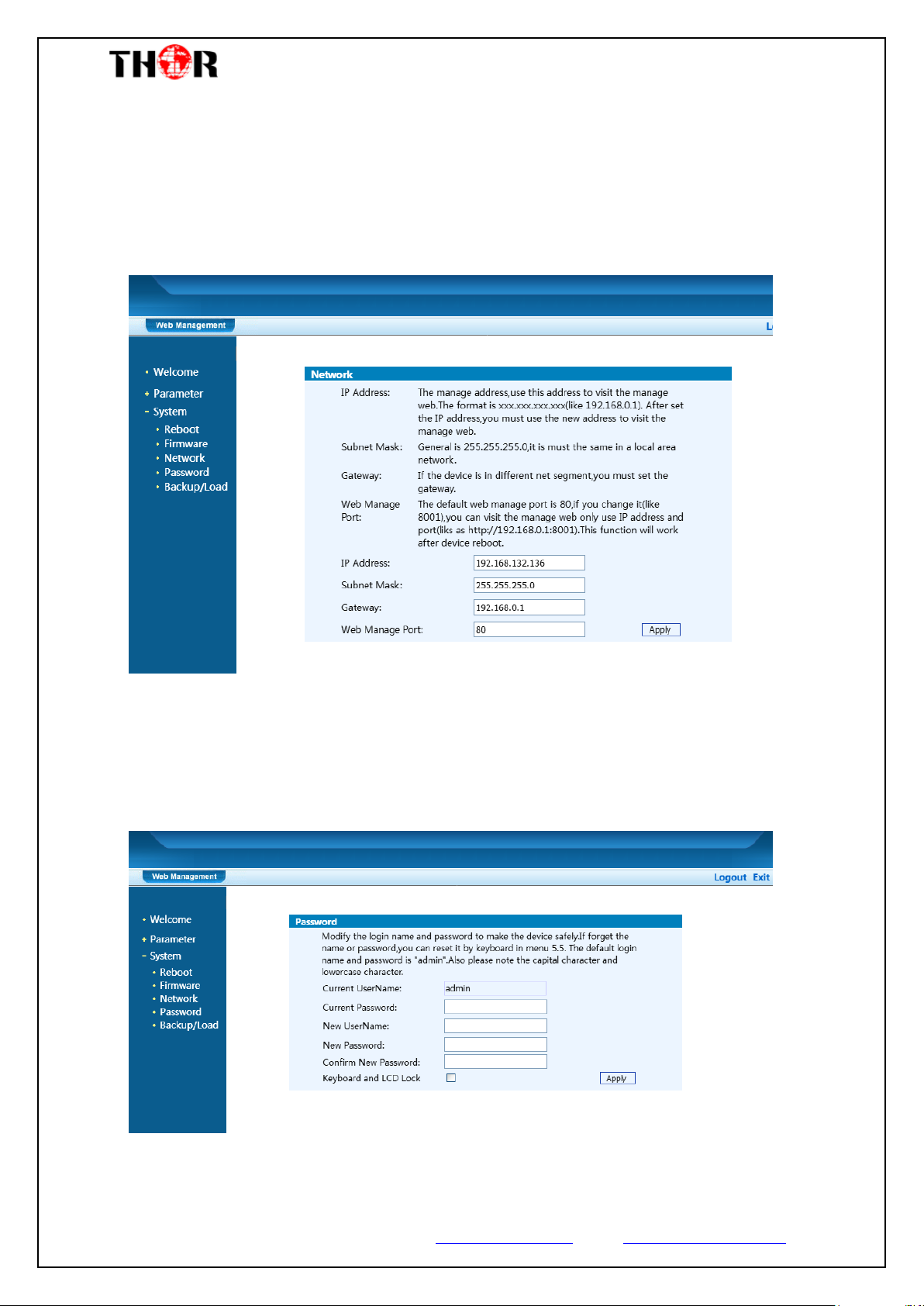
Network
When user clicks “Network”, it will display the screen as Figure-11. It displays the
network information of the device. Here user can change the device network
configuration as needed.
Figure-11
Change Password
When user clicks “Password”, it will display the password screen as Figure-12. Here
user can change the Username and Password for login to the device.
Figure-12
Thor Fiber 2017 Tel: (800) 521-8467 Email: [email protected] www.thorbroadcast.com
Page 29
H-4HD-EMS & EMH
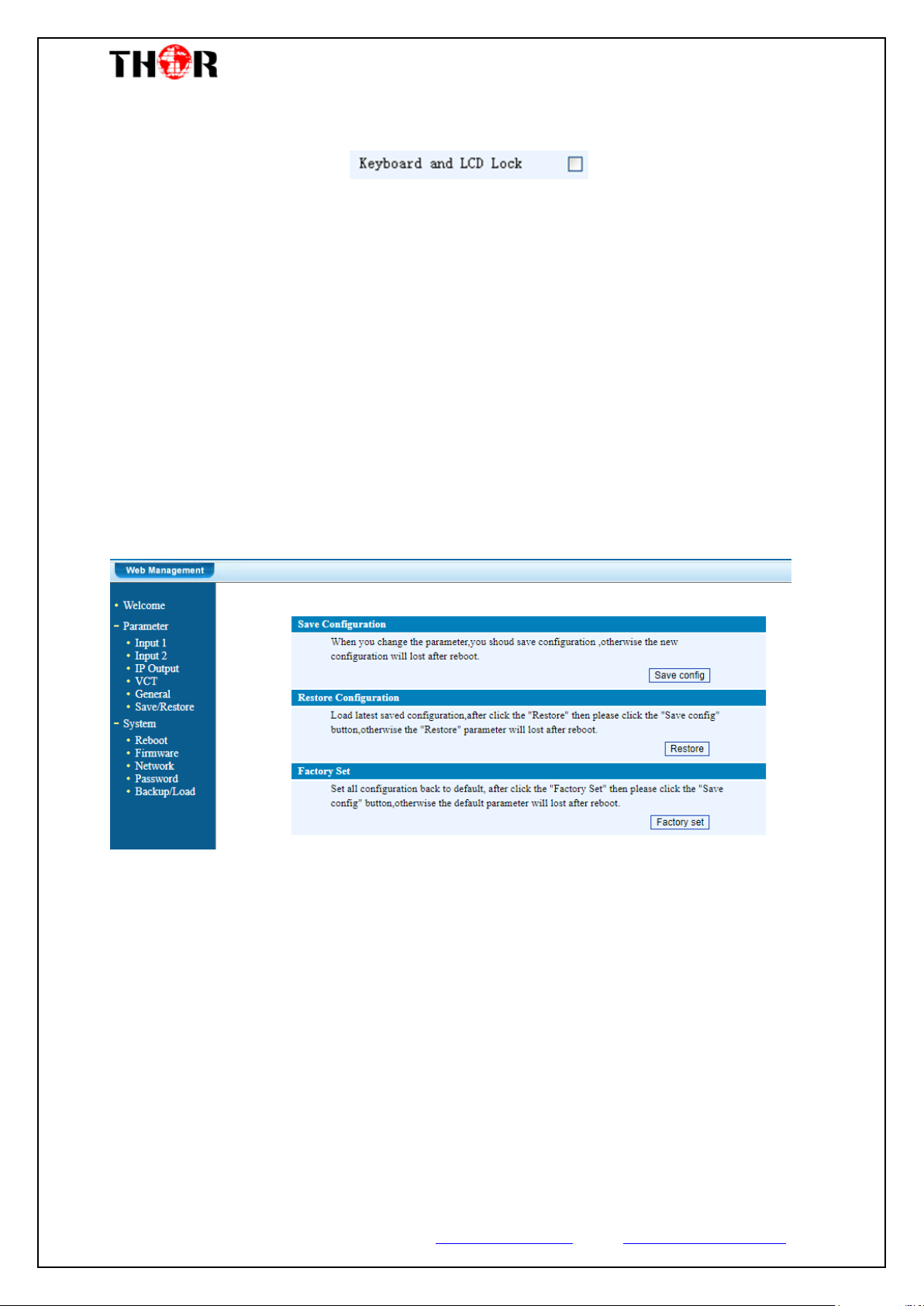
Keyboard and LCD Lock: If it is marked with
“√”,the LCD and keyboard will be locked to avoid unrelated users’ modifying or view
the device information and configurations. User can’t operate the keyboard & LCD
while only the device IP address can be noted in the LCD window.
Backup/Load
Click “Backup/Load” from the menu
Backup Configuration – To back up the device configuration file to a folder
Restore Configuration – Loads the most recently saved configuration
Load Configuration – If you needs to load the old configuration to the device, click
“Browse” and find the backup configuration file path. After selecting the file, click
“Load File” to load the backup file to the device.
Figure-13
Thor Fiber 2017 Tel: (800) 521-8467 Email: [email protected] www.thorbroadcast.com
Page 30

H-4HD-EMS & EMH
Chapter 5 Troubleshooting
THOR’s ISO9001 quality assurance system has been approved by the CQC
organization. We guarantee the products’ quality, reliability and stability. All THOR
products haven passed all testing and manual inspections before they are shipped out.
The testing and inspection scheme already covers all the Optical, Electronic and
Mechanical criteria which have been published by THOR. To prevent a potential
hazard, please strictly follow the operation conditions.
Prevention Measures
Installing the device in a place where the environmental temperature is
between 0 to 45 °C
Making sure the unit has plenty of ventilation for the heat-sink on the rear
panel; and other heat-sink bores if necessary
Checking the AC input within the power supply and ensure it is working, the
connection is correctly installed before switching on device
Checking the RF output levels to stay within a tolerable range, if it is
necessary
Checking all signal cables have been properly connected
Frequently switching on/off device is prohibited; the interval between every
switching on/off must be greater than 10 seconds.
Conditions needed to unplug power cord
Power cord or socket damage.
Any liquid that got into the device.
Any stuff that could cause a circuit short
Device in damp environment
Device has suffered from physical damage; i.e. it fell off a rack.
Longtime idle.
After switching on and restoring to factory setting, device still won’t work
properly.
Maintenance needed on device
Thor Fiber 2017 Tel: (800) 521-8467 Email: [email protected] www.thorbroadcast.com
Page 31

H-4HD-EMS & EMH
Chapter 6 Packing List
H-4HD-EMS or EMH Encoder 1PC
User Manual 1PC
HDMI/SDI Cables 4PCs
Power Cord 1PC
For Further Tech Support
1-800-521-Thor(8467)
Thor Fiber 2017 Tel: (800) 521-8467 Email: [email protected] www.thorbroadcast.com
 Loading...