

Thoreson-McCosh HMI/T-3 Instruction Manual
Thoreson-McCosh Inc
HMI/T-3 DRYER
HMI / T-3
OFF
TEMP
AU TO
TIM E
AU T O
ON
DEW
POINT
INSTRUCTION MANUAL
IB201001
OPT
1
4
2
5
87
3
6
9
0
1885 Thunderbird St. Troy MI. 48084
THORESON-McCOSH INC
Phone 1-248-362-0960
Fax 1-248-362-5270
sales@thoresonmccosh.comsales@thoresonmccosh.com

Thoreson-McCosh Inc
FORWARD
The information contained in this Instruction Manual is provided to you for the
maintenance of your Thoreson-McCosh equipment.
Also included in this manual are operating instructions, a service parts list, and
wiring diagrams. Please file this manual for future use.
For additional information, please contact:
THORESON-McCOSH Inc.
1885 Thunderbird Street
Troy, MI 48084
Phone: (248) 362-0960
Facsimile: (248) 362-5270
sales@thoresonmccosh.comsales@thoresonmccosh.com
CUSTOMER RECORDS
Upon receipt of your Thoreson-McCosh equipment, it is very important that you
complete the table below. The information will be needed to best serve you when
you call the Thoreson-McCosh Service Department with questions or to order
replacement parts. The information is located on the Serial Tag on the unit and
inside the door of the control box.
Model Name _____________________________________
Serial No. _____________________________________
Wiring Diagram No. _____________________________________
Insert No. _____________________________________
Program No. _____________________________________
Layout No. _____________________________________
High efficiency resin handling and preparation equipment for the plastics industry

Thoreson-McCosh Inc
Table of Contents
SECTION 1: WARRANTY......................................................................................... 3
SECTION 2: TD DRYER MECHANICAL METHOD OF OPERATION ......................... 4
2.1: INTRODUCTION .................................................................................. 4
2.2: TRIPLE BED METHOD OF OPERATION.............................................. 5
2.3: QUICK START ..................................................................................... 6
2.4: POWER CONNECTIONS ..................................................................... 6
2.5: UNITS WITH COMPLETE DRYING HOPPER....................................... 7
2.6: UNITS WITH HOPPER EXTENSION .................................................... 7
SECTION 3: TECH 3 INSTRUCTIONS...................................................................... 8
3.1: DISPLAYING THE PROGRAM # & CYCLE TIMES................................ 8
3.2: OPERATOR INTERFACE PANEL......................................................... 8
3.3: DESCRIPTION OF THE KEYPAD......................................................... 9
3.3: SPECIAL KEYS.................................................................................... 9
SECTION 4: TEMPERATURE SET POINTS ............................................................. 10
4.1: CHANGING DISPLAY FROM F TO C. .................................................. 10
4.2: MODIFYING THE PROCESS TEMPERATURE SETPOINT................... 10
4.3: REGENERATION TEMPERATURE DISPLAY....................................... 10
4.4 SOLID STATE RELAYS & MASTER HEATER CONTACTOR ................ 11
4.5 WATER SAVER VALVE TEMPERATURE DISPLAY ............................. 11
SECTION 5: DELTA-T OPTION ................................................................................ 12
5.1: INTRODUCTION TO DELTA-T ............................................................. 12
5.2: READING THE DELTA-T FIRST SCREEN............................................ 12
5.3: MODIFYING THE PROCESS DELTA TEMPERATURE SETPOINTS..... 13
SECTION 6: TIME/AUTOSTART SETPOINTS. ......................................................... 15
6.1: SETTING THE AUTO START AND AUTO STOP FUNCTIONS.............. 15
6.2: VIEWING CURRENT CYCLE TIMES.................................................... 16
6.3: SETTING THE CURRENT DAY AND TIME........................................... 16
SECTION 7: DEWPOINT.......................................................................................... 16
7.1: DEWPOINT SETPOINTS...................................................................... 16
7.2: SETTING THE DEWPOINT SHIFT SETPOINT...................................... 16
7.3: SETTING THE DEWPOINT ALARM SETPOINT.................................... 17
SECTION 8: OPTIONAL SETPOINTS....................................................................... 17
8.1: CFM..................................................................................................... 17
8.2: FORCING A BED INDEX...................................................................... 18
8.3: REGEN BLOWER OFF-DELAY TIMER................................................. 18
8.4: SETTING THE REGEN BLOWER OFF-DELAY..................................... 19
8.5: SETTING THE SHIFT-DELAY............................................................... 19
SECTION 9: PRELIMINARY TD DRYER CHECKS.................................................... 20
9.1: VISUALLY CHECK DRYING SYSTEM.................................................. 20
9.2: CHECK DRYING HOPPER INLET TEMPERATURE ............................. 20
9.3: CHECK THE HOPPER TEMPERATURE DISTRIBUTION ..................... 20
9.4: CHECK DRYER RETURN AIR TEMPERATURE................................... 20
9.5: CHECK DISCHARGE DEW POINT OF THE DRYER ............................ 20
EDITION 05/07/10 1 IB201001.doc

Thoreson-McCosh Inc
SECTION 10: MAINTENANCE.................................................................................... 21
10.1: FILTERS .............................................................................................. 21
10.2: LUBRICATION ..................................................................................... 21
10.3: MOLECULAR SIEVE TEST .................................................................. 21
10.4: DESICCANT BED RECHARGING PROCEDURE .................................
(TD-12 THRU TD-360) ......................................................................................... 22
DESICCANT BED RECHARGING PROCEDURE .................................
(TD-480 THRU TD-2000)...................................................................................... 23
10.5: DEWPOINT SENSOR REPLACEMENT................................................ 24
10.6: DISPOSAL OF MERCURY CONTACTORS........................................... 24
10.7: MAINTENANCE SCHEDULE................................................................ 25
SECTION 11: ALARM MESSAGE CHART .................................................................. 26
SECTION 12: ADDITIONAL INFORMATION ............................................................... 27
TD DRYERS COMMON SPARE PARTS LIST....................................... 27
MAIN CONTROL BOARD ..................................................................... 28
THERMISTOR CALIBRATION .............................................................. 29
TD DRYER MECHANICAL SCHEMATICS ............................................ 30
TD DRYER PARTS LIST ...................................................................... 31
MERCURY MSDS ................................................................................
MOLECULAR SIEVE MSDS .................................................................
WIRING DIAGRAMS.............................................................................
EDITION 05/07/10 2 IB201001.doc

Thoreson-McCosh Inc
SECTION 1 THORESON-MCCOSH PRODUCT WARRANTY
Thoreson-McCosh warrants each product of its manufacture to be free from defects in
material and workmanship for a period of 30 months (2-1\2) year from the date of delivery
to the original purchaser. Thoreson-McCosh’s obligation under this warranty is limited to
repairing or replacing any part returned to the Thoreson-McCosh factory with transportation
charges prepaid, and which, on examination by Thoreson-McCosh, shall disclose to
Thoreson-McCosh’s satisfaction to have been defective.
The purchaser must notify Thoreson-McCosh of such defects and promptly deliver the
defective part(s) in accordance with Thoreson-McCosh’s shipping instructions, delivery
prepaid. Parts will be replaced F.O.B. Thoreson-McCosh factory, by Thoreson-McCosh,
and will be invoiced to the purchaser with "credit on return of defective part", if the part is
returned within fifteen (15) days after shipment of replacement part. Thoreson-McCosh is
not liable for installation or cost to install the replacement part or removal of the defective
part.
Thoreson-McCosh is not responsible for any failure of its product due to improper use,
installation, or operation. Thoreson-McCosh shall not assume any expense or liability for
repairs made to any Thoreson-McCosh unit or equipment outside Thoreson-McCosh’s own
factory unless specifically agreed to in writing by Thoreson-McCosh.
Equipment and accessories furnished by us, but manufactured by others, are guaranteed
to the extent of the original manufacturer’s guarantee to Thoreson-McCosh, if that
guarantee exceeds one (1) year.
It is expressly understood that Thoreson-McCosh is not responsible for damage and/or
injury caused to buildings, contents, products, or persons by reason of installation or use of
any of our products. Thoreson-McCosh shall not be liable for loss, damage or expenses
arising directly or indirectly from, or being consequential or incidental to, the use of its
products or from any other cause.
The above warranty supersedes, and is in lieu of all other warranties expressed or implied;
and no person, agent, representative or dealer is authorized to give any warranties on
behalf of Thoreson-McCosh, not to assume for Thoreson-McCosh any other liability in
connection with Thoreson-McCosh products.
EDITION 05/07/10 3 IB201001.doc

Thoreson-McCosh Inc
SECTION 2 TD DRYER MECHANICAL METHOD OF OPERATION
SECTION 2.1 INTRODUCTION
Your Thoreson-McCosh dryer was thoroughly tested prior to shipment and checked to
insure that its performance is up to specifications. Upon arrival in your plant, the unit
should be carefully inspected for physical damage which might have occurred in
transportation. Should any damage be observed, it should be reported to the carrier at the
earliest possible time.
Dryers are held to the crate bottom with a Z bracket. The side panels must be removed
before the Z brackets can be removed. Use a hi-low or a lift to raise the unit off of the crate
bottom. We recommend that a person steady the unit while on the hi-low.
NOTE:
For the TD-150 and up, there are cross supports and some wood supports to secure
the beds during shipping, these must be removed before power and air are
connected to the unit. Failure to remove these items will damage the unit.
The dryer should be located as close as possible to the material drying hopper it will
service. This will minimize thermal and air flow losses. The unit should be placed on any
reasonable level area or platform. The unit should be connected to the power source
indicated on the model nameplate. If the return air temperature will be above 165F/ 74C,
than an After-Cooler should be installed into your unit.
This dryer is a triple desiccant bed unit which continuously removes moisture from the
process air stream by adsorption. While two of the beds are adsorbing moisture from the
process air, the third is being automatically recharged.
This unit is a re-circulating dryer, recycling the drying air from the material hopper through
the desiccant beds. The regeneration air flow is completely independent of the process air
flow. The only atmospheric air that enters the process system is a small quantity which
may leak in via the material loading system, if present on the hopper. A process air filter
and regeneration air filter are provided to prevent contaminates from reaching the desiccant
material.
EDITION 05/07/10 4 IB201001.doc

Thoreson-McCosh Inc
SECTION 2.2 TRIPLE BED METHOD OF OPERATION
The operation of the triple bed dryer is based on each of the three beds being indexed to
one of three separate stations within the unit.
The first position is the regeneration station. Here, super-heated ambient air is blown
through the bed to remove adsorbed moisture from the desiccant material. This moisture is
exhausted to the atmosphere near the bottom of the dryer.
The second position is the cool down station. Here, a small percentage of return air from
the hopper passes through the bed to gradually cool down the hot desiccant material. The
heat captured by this air is used to heat the process air, thus minimizing process heater
energy requirements. As the bed cools, it begins to contribute to the material drying
process.
The third position is the process station. Here, the rest of the return air from the hopper
passes through this desiccant bed. The dried, cooled, desiccant material is now permitted
to adsorb any moisture removed from the plastic resin that is carried in with the return air,
before it is heated and sent back to the drying hopper in a completely closed loop cycle.
Automatic indexing of the beds is performed by separating the manifolds upper and lower
airflow from the desiccant beds with an electric lineal actuator motor. The beds are then
rotated with a gear motor/chain drive assembly. A limit switch stops the beds at the next
sequential station. The lineal actuator motor then clamps the manifold seals located on the
upper and lower air flow manifolds against the beds for an airtight operation.
On standard units, the automatic bed indexing time cycle is controlled by the
microprocessor, which is maximized to guarantee very dry process air, even while
operating under extremely severe drying conditions.
In the optional dewpoint control mode, the dewpoint of the process air is continuously
monitored. Automatic bed indexing will occur only when the dewpoint is approaching an
unacceptable level.
The process air heating elements are located in the heater box which is nearest the control
box mounted on the upper deck. An indicating light is provided to indicate when the
process heater elements are activated.
The regeneration air heating elements are located in the heater box, on the upper deck,
furthest from the control box. On standard units the regeneration heater and blower are
timed to be on during the first portion of the bed index cycle, and off during the remainder of
the cycle. Only units with the optional regeneration power saver, the heaters and blower
will shut off early if the regeneration of the bed is sensed as being completed (regeneration
exhaust temperature reaches a minimum of 325°F/ 163°C). An indicating light is provided
to indicate when the regeneration heater elements are on.
EDITION 05/07/10 5 IB201001.doc

Thoreson-McCosh Inc
SECTION 2.3 QUICK START
NOTE: Please read this section, as it contains information not found elsewhere in the
manual. Most steps will refer you to the correct section for reference.
1. Uncrate equipment (Section 2.1).
2. Clean drying hopper. All hoppers are shipped with a light coat of oil.
3. Connect power. (Section 2.4)
4. Connect water lines to after-cooler (optional equipment). Requires 3 to 4 gallons per
minute, maximum 100 P.S.I., 80°F/ 27°C.
5. Connect compressed air to the units requiring compressed air. (TD-480 & up). 60 P.S.I.
minimum, 120 P.S.I. maximum.
6. Check process blower rotation (Section 2.4).
7. Connect Air hoses. The smaller diameter red process hose connects from the dryer to
the diffuser on the hopper. The black hose returns air from the connection near the top
of the hopper back to the dryer unit.
8. Set process temperature setpoint (Section 4).
9. Visually inspect drying system (Section 9.1).
10. Fill hopper with material.
11. Begin drying, giving first batch of material sufficient residence time before beginning to
use material (typically 3 to 4 hours). Check with resin manufacturer.
SECTION 2.4 POWER CONNECTIONS
The power line terminals are identified as L1, L2, and L3. All heater and blower circuits are
individually fused. It is highly recommended, and required by many local codes, that a
fusible disconnect of adequate capacity be installed by user. The unit is ready to operate
after connecting the power lines to their respective terminals and properly grounding the
machine.
Blower motor rotation on three phase units must be checked when the unit is first started
and after any reconnection of power to the unit. All Tech-3 dryers from the TD-12 up to the
TD-360 include a Blower Rotation Alarm. This alarm will activate the alarm light and
display a message on the digital readout indicating that the dryer is phased incorrectly.
On larger dryers (TD-480 and above), the Blower Rotation Alarm is optional. If the alarm is
not included on your dryer, you must check that the process blower is rotating in the right
direction by removing the side panel and checking that the process blower motor is rotating
clockwise.
To correct the blower rotation, reverse any two of the three incoming power leads to the
terminal block. Do not swap the power leads at the blower itself.
CAUTION: The correct phase is extremely important. Incorrect phasing can damage the
dryer.
EDITION 05/07/10 6 IB201001.doc

Thoreson-McCosh Inc
SECTION 2.5 UNITS WITH COMPLETE DRYING HOPPER
Clean the inside of your hopper thoroughly to avoid contamination of plastics resin to be
processed. Install the balanced flow air diffuser inside of the drying vessel with the
mounting plate and bolts supplied. Your drying hopper is made in two sections for ease of
cleaning and installation. To remove the barrel of the hopper, lift it out of its “seat” on the
hopper cone. If you have purchased a machine-mounted hopper, install the hopper cone
mounting plate to the feed throat of your molding machine, being sure that it is well
secured. Refit the hopper barrel into its “seat” on the hopper cone, being sure that it is
located and clamped properly with the stainless steel ring clamp provided.
NOTE: The T-bolt should have a light application of grease on the threads or the Tbolt will score and lock-up in the clamp.
SECTION 2.6 UNITS WITH HOPPER EXTENSIONS
Clean the inside of your extension thoroughly to avoid contamination of plastic resin. Install
the balanced flow air diffuser with the mounting plate and bolts supplied.
Place the extension on your machine hopper, being sure that the extension is centrally
located on the machine hopper and properly secured.
EDITION 05/07/10 7 IB201001.doc
Thoreson-McCosh Inc
SECTION 3 TECH 3 INSTRUCTIONS
SECTION 3.1 DISPLAYING THE PROGRAM # & CYCLE TIMES
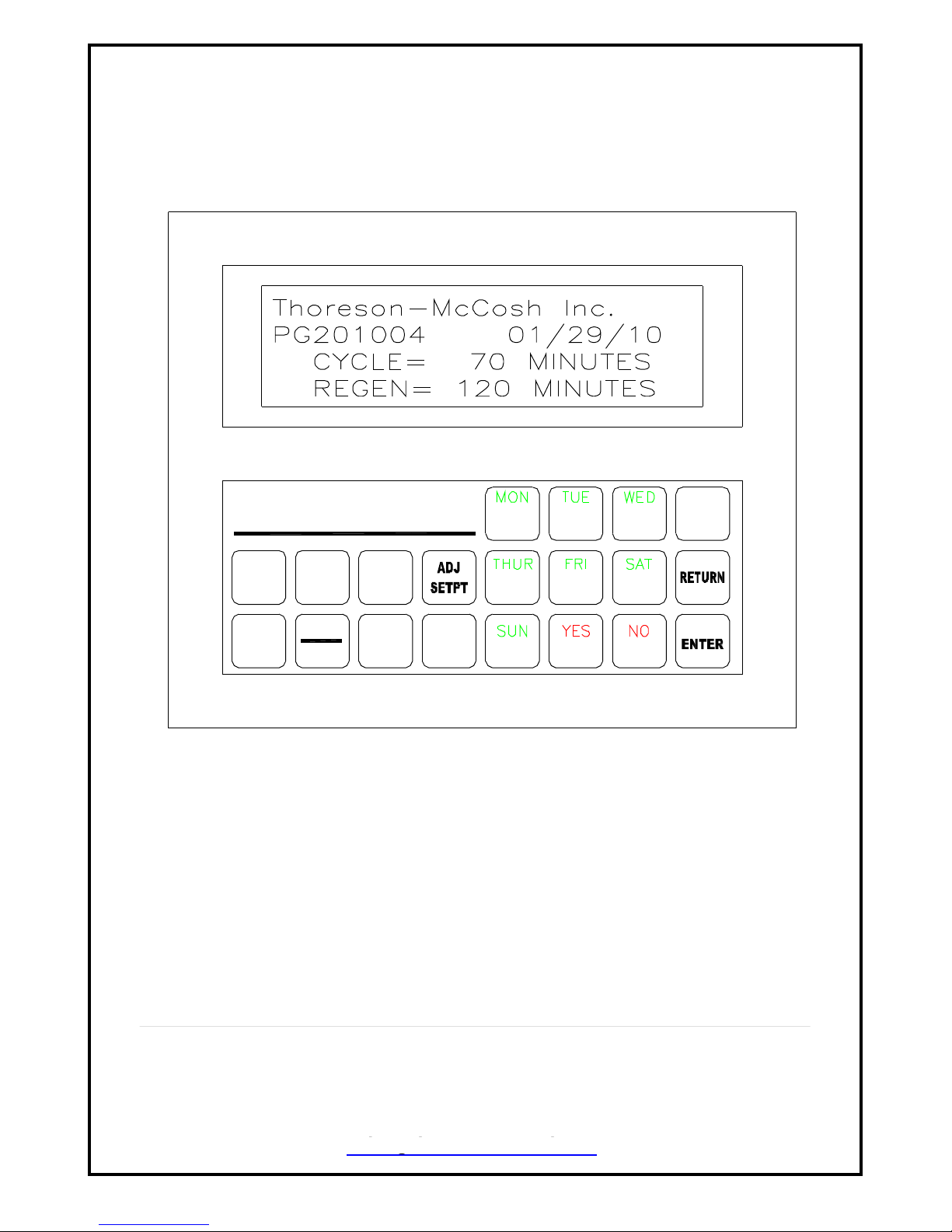
When the dryer is first powered up, for a few seconds, the screen will display the Program
# and the Dryer Process & Regen Cycle times.
SECTION 3.2 OPERATOR INTERFACE TERMINAL
The operator interface terminal includes:
20 key touchpad with dual functions;
Four line by 20 character Liquid Crystal Display.
HMI / T-3
AUTO
OFF
TEMP
FIGURE 3.2 OPERATOR INTERFACE TERMINAL:
Display shows the Key Pad and the “Start-up Screen.”
EDITION 05/07/10 8 IB201001.doc
TIME
AUTO
ON
DEW
POINT
OPT
1
4
2
5
87
0
3
6
9
Thoreson-McCosh Inc
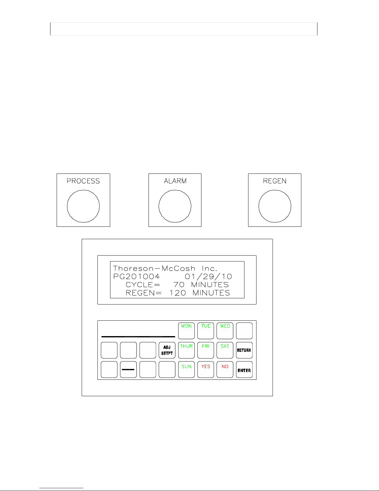
SECTION 3.3 DESCRIPTION OF KEYPAD
The keypad consists of twelve regular function keys, similar to a pocket calculator, and
eight special keys, that allow monitoring and adjusting of the setpoints.
SECTION 3.4 .SPECIAL KEYS
OFF Turns the dryer Off
AUTO Puts the dryer into Auto Mode so the seven day timer can be utilized.
ON Turns the dryer On.
ADJ SETPT Toggles off and on to enable the ability to change or just view setpoints
TEMP Is used to adjust or view the temperature setpoints.
TIME/AUTO Is used to adjust or view the Present day and time and the AUTO setpoints.
DEW POINT Is used to adjust or view the DEW POINT setpoints.
NOTE: Pressing the “RETURN” key in most cases will abort the current operation and
return the display to the First Screen
HMI / T-3
OFF
TEMP
FIGURE 3.4 FIRST SCREEN:
Display shows the first screen.
EDITION 05/07/10 9 IB201001.doc
AUT O
TIM E
AU TO
ON
DEW
POIN T
OPT
1
4
7
2
5
8
3
6
9
0

Thoreson-McCosh Inc
SECTION 4 TEMPERATURE SETPOINTS
SECTION 4.1 CHANGING THE TEMPERATURE DISPLAY FROM FAHRENHEIT TO
CELSIUS
Locate SW1 on the main control board (see page 29) and move Dip Switch #1 to the on
position. All Fahrenheit temperature readings will be converted to Celsius.
NOTE: Because the unit is converting from F to C, the Celsius setpoint entered may be a
few degrees above or below the desired setpoint.
SECTION 4.2 MODIFYING THE PROCESS TEMPERATURE SETPOINT (PLASTIC
RESIN DRYING TEMPERATURE)
When the “TEMP” key is pressed, the display shows the current process setpoint and
allows the user to enter a new process setpoint.
Select the new setting, then press enter. The display will go back to the first screen.
P r o c e s s S e t p o i n t = 1 0 0 F
N e w = 2 2 5 F
P r e s s E N T E R
FIGURE 4.2 Editing the Process Temperature Setpoint
SECTION 4.3 REGENERATION & PRE-COOLER EXHAUST TEMPERATURE DISPLAY
Two consecutive presses of the Temperature Setpoints key displays the regeneration
temperature, the Return Air Temperature and the Regen Exhaust temperature if the Regen
Power saver option was installed.
R E G E N T e m p = 5 5 0 F
R E G E N E x h a u s t = 2 2 5 F
R e t r n A i r T e m p = 1 6 5 F
P r e s s R E T U R N
FIGURE 4.3 Viewing the Regeneration, Return Air and the Pre-Cooler Dryer Exhaust
Temperature.
NOTE: Dryer Exhaust temperature is displayed only if the Pre-Cooler option is purchased.
This allows the user to monitor the regeneration temperature, the Return air Temperature
and the Pre-Cooler Dryer Exhaust Temperature for trouble-shooting. You can return to the
First Screen by pressing the “RETURN” key. The regeneration temperature setpoint
cannot be modified and has been preset to provide your unit with an optimum regeneration
cycle. The Pre-Cooler Water Valve Control will monitor the temperature of the Pre-cooler
dryer exhaust temperature.
EDITION 05/07/10 10 IB201001.doc

Thoreson-McCosh Inc
SECTION 4.4 SOLID STATE RELAYS & MASTER HEATER CONTACTOR
The Solid State Relay, or SSR, is the accepted way to replace the Mercury contactors.
Since SSRs normally close when they malfunction, a Master Heater Contactor, or MHC, is
installed ahead of the SSR. The MHC is controlled by a safety thermostat, that opens
when the heater temperature has exceeded the maximum controlled temperature. The
Process is 425F (218C), and the Regen is 575F (302C). To keep the cost of controls
down, on 3 phase heater banks, the center leg of power is not interrupted by the SSR, so
the MHC is also open when the dryer is in the OFF position, this disables all three power
legs
SECTION 4.5 PRECOOLER & WATER SAVER VALVE
When drying a resin below 170F (77C), a pre-cooler will need to be installed on the dryer.
There is a water valve installed to control the flow of water. The valve will open when the
air temperature exiting the pre-cooler is 1F (-1C), above the Process Set point. There is
an orifice installed in the out port of the water valve, that allows a reduced flow of water
through the valve.
EDITION 05/07/10 11 IB201001.doc

Thoreson-McCosh Inc
SECTION 5 DELTA-T OPTION
SECTION 5.1 INTRODUCTION TO DELTA-TEMPERATURE
The Delta T function determines the material has achieved an acceptable dry level based
on the idea that when the hopper air return temperature approaches the hopper air inlet
temperature, the material is dry. Obviously, due to losses of energy in a drying
environment, the air inlet and outlet will never be the same, but at some point, the
difference is small enough to indicate that the material can be considered dry. At this point,
the process air flow heaters will turn off. The process blower will continue to cycle keeping
positive dry air pressure in the drying hopper. This will prevent the material from being over
dried and also keep it from being saturated with moisture. This also saves energy.
The Process Setpt should be set to the drying temperature recommended by the material
manufacturer or supplier. The Hop Exh Setpt is determined by drying the material for the
manufactures suggested residence time. (typically 3 to 4 hours). Note the Hop Exh Temp
at the end of the residence time and set the Hop Exh Setpt at this temperature. If the Hop
Exh Temp falls below the Low Temp Return Setpoint, the Process heaters will come back
on.
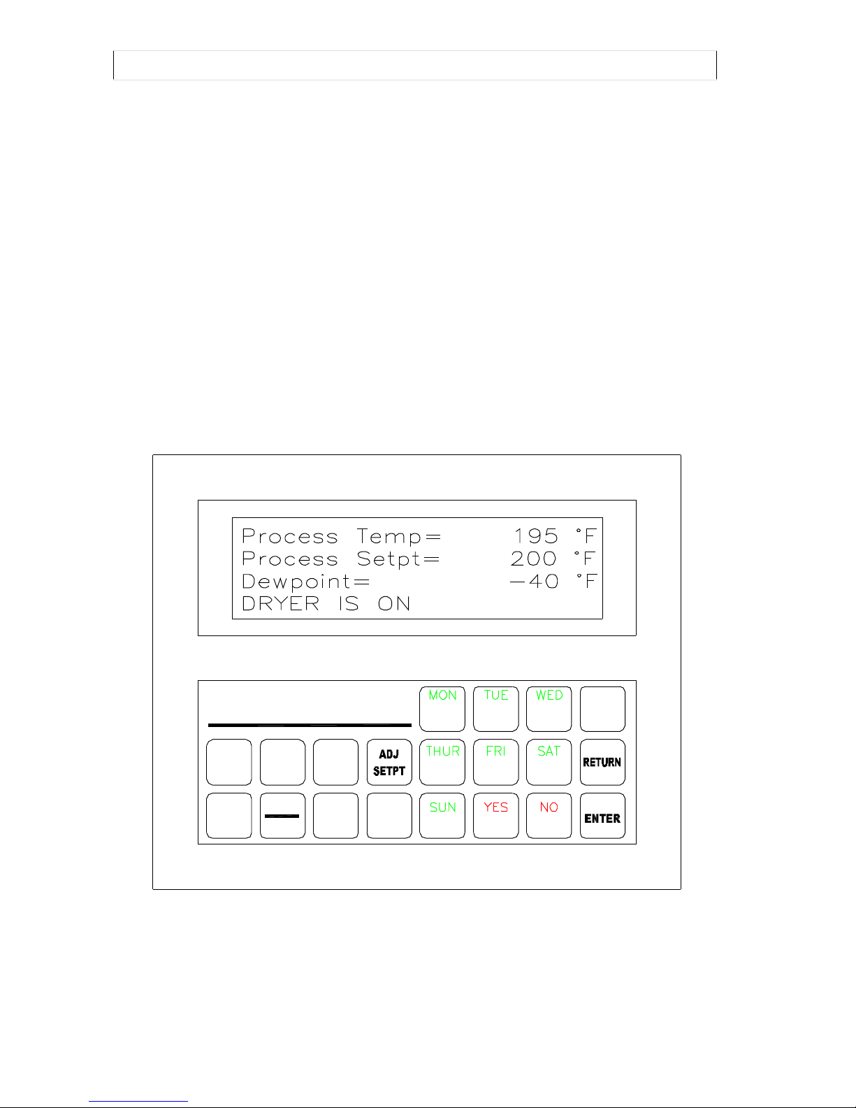
SECTION 5.2 READING THE DELTA-T FIRST SCREENS
The first screen is special for the Delta T dryer. The first screen is actually made of 2
screens that will scroll from one to the other. To freeze the screens, Press the ENTER key,
to make the screens resume scrolling, press the RETURN key.
P r o c e s s S e t p t = 2 2 5 ° F
P r o c e s s T e m p = 2 2 4 ° F
H o p E x h S e t p t = 1 8 5 ° F
H o p E x h T e m p = 1 8 0 ° F
R e g e n T e m p = 2 2 5 ° F
D e w p o i n t = - 4 0 ° F
( D r y e r A l a r m )
D r y e r i s O N
FIGURE 5.2 The Delta-T First Screens Display
EDITION 05/07/10 12 IB201001.doc

Thoreson-McCosh Inc
SECTION 5.3 MODIFYING THE DELTA-T PROCESS TEMPERATURE SETPOINT
When the “TEMPERATURE SETPOINTS” key is pressed, the display shows the current
process setpoint and allows the user to enter a new process setpoint.
P r o c e s s S e t p o i n t = 1 0 0 F
N e w = 2 2 5 F
P r e s s E N T E R
FIGURE 5.3.1 Editing the Delta T Process Temperature Setpoint
H o p p e r E x h a u s t
S e t p t = 1 8 5 F
N e w = 1 8 0 F
P r e s s E N T E R
FIGURE 5.3.2 Editing the Hopper Exhaust Setpoint
L o w T e m p R e t u r n
S e t p t = 1 0 F
N e w = F ( 0 5 t o 1 5 )
P r e s s E N T E R
FIGURE 5.3.3 Editing the Low Temp Return Setpoint
SECTION 5.4: DELTA-T EXAMPLE
Resin Manufacture suggested drying temperature. 225F (107C)
Hopper Exhaust temperature after 3 hours: 195F (91C)
Low Temp Return
Small hopper 11-15
Med hopper 8-10
Large hopper 5-7
Process Setpoint .............................................225 F (107C)
Hopper Exhaust Setpoint................................195F (91C)
Low Temp Return Setpoint.............................9 (medium hopper)
EDITION 05/07/10 13 IB201001.doc
Thoreson-McCosh Inc
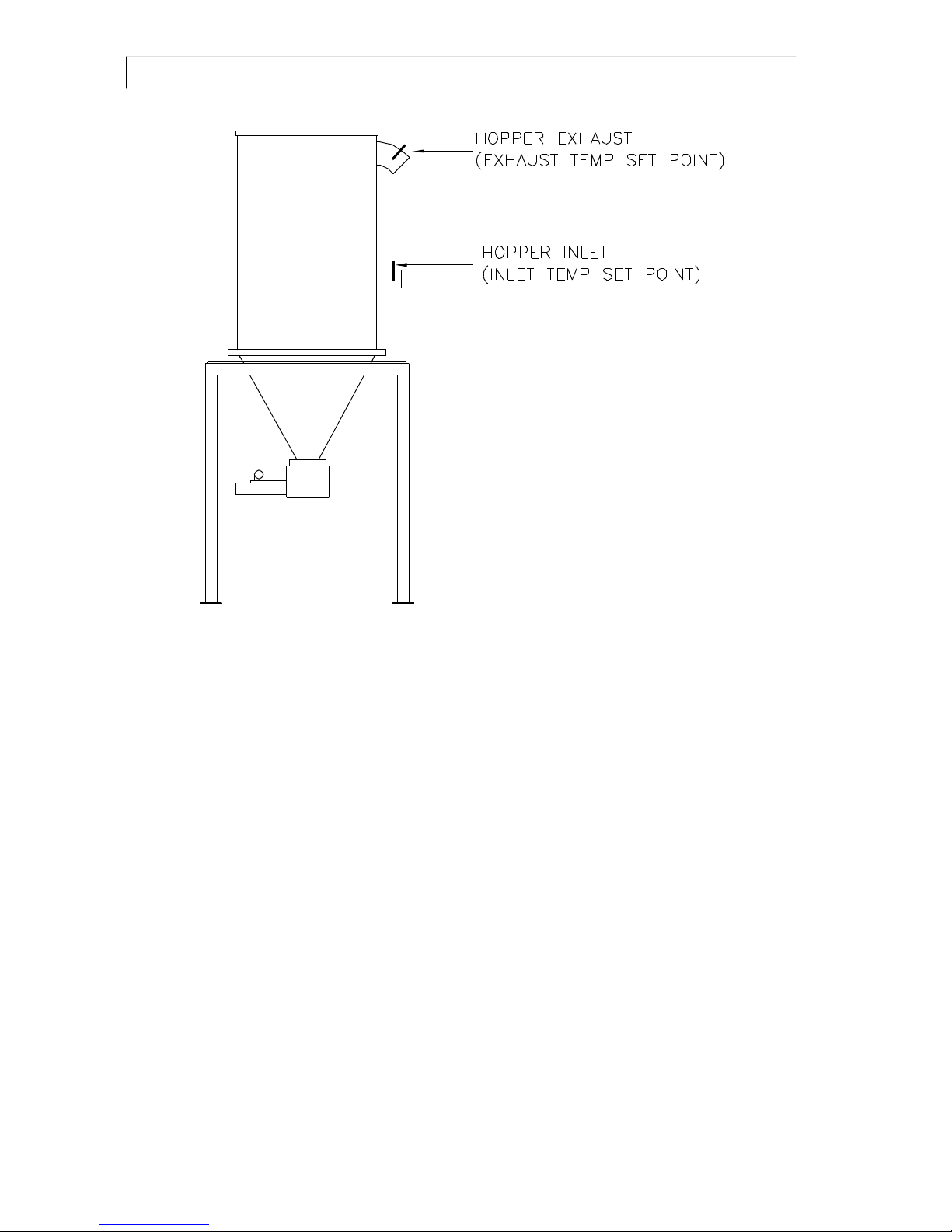
FIGURE 5.4 DELTA-T HOPPER PROBE CONFIGURATION
EDITION 05/07/10 14 IB201001.doc
 Loading...