

Page 1

MCU500 Mobile Locator and Control
Unit
Hardware Reference Manual
Page 2

Part Number 100-00191
Revision 1.01
Page 3

Copyright © 2000-2001 by Thorcom Systems Limited.
ALL RIGHTS RESERVED
This document may not be copied in part or in whole, stored on magnetic tape or disc or in an
information retrieval system, or used in any way without permission from the p ublisher.
The information contained in this document has been carefully checked and is believed to be
accurate and reliable, however, no responsibility is assumed for inaccuracies. Thorcom Systems
Limited reserve the right to m ake changes to this docum ent and th e assoc iated product in line with
its policy of continued improvement. Thorcom Systems Limited does not assume any
responsibility for direct or consequential damage to, or loss of, property or income through the use
or inability to use th is produc t.
The equipm ent de scribed in this d ocument m ust be installed, o perated and m ain tained in
accordance with the written procedures described herein, and should not be used for any purpose
that involves the safe ty of life or limb, an d should not form any part of a life supp ort system .
Details and descriptions of the product, methodology and design supplied in this documentation
are cons idered part of the product a nd are co vered by the manufacturer's Intellectual Prope rty
Rights. Information provided in this documentation is to allow the customer to use, install and
maintain the equip ment described and does no t transfer a ny rights to su ch Intellectu al Property
Righ ts, Pa tents or C opyrig hts to the c ustomer or any third party.
For furth er inform ation on this produ ct please c ontact Technical Support at:
Thorcom Systems Limited
Unit 4
96B Blackpole Trading Estate W est
Worcester WR3 8TJ
England, U. K.
Tel: 01 905 756700 (international: +44 1 905 756700)
Fax: 01 905 755777 (international: +44 1 905 755777)
Email: support@thorcom.co.uk
Web Site: http://www.thorcom.co.uk
Part Number: 100-00191
Page 4

Revision: 1.01
Date: 5 April 2001
Reference: \\Pendragon\documents\Manuals\Products\mcu500\Hardware-100-00191-rev-101.wpd
Page 5

Document Revision History
Date RevisionInitial
s
Description
26/11/2000 1.00 MJT New document
05/04/2001 1.00 MJT Revised jumper settings and fixed typos
Page 6

Contents
1. Introduction ................................................... 1
1.1 Scope of document ...................................... 1
1.2 Other documentation ..................................... 1
2. Product variants, facilities and options .............................. 2
2.1 Power supply variants .................................... 2
2.2 System memory size ..................................... 2
2.3 Program memory size and type ............................. 2
2.4 Enclosure .............................................. 3
2.4.1 Front panel layout ................................ 3
2.4.2 Status LEDs ..................................... 3
2.4.3 Rear panel ...................................... 3
2.5 Deep sleep timer ........................................ 4
2.6 Application firmware ...................................... 4
3. Installation and operation ........................................ 5
3.1 Installation ............................................. 5
3.2 Power connection ....................................... 5
3.3 Connection to radio communications equipment ................ 6
3.4 GPS antenna selection ................................... 6
3.4.1 Standard GPS antennas ........................... 6
3.4.2 Alternative GPS antennas .......................... 7
4. Interfaces and connectors ....................................... 8
4.1 Power and input/outputs .................................. 8
4.2 COM1serial port ......................................... 9
4.3 COM2 serial port ........................................ 9
4.4 Auxiliary port .......................................... 10
4.5 GPS antenna connector ................................. 11
5. Maintenance and trouble shooting ................................ 12
5.1 Removing the PCB from the case .......................... 12
5.2 Changing the firmware EPROM/FLASH device ................ 12
5.3 Trouble shooting ....................................... 13
5.3.1 No response from the MCU500 ..................... 13
5.3.2 Unit unable to send location updates ................. 13
5.3.3 Unit not correctly programmed ...................... 13
6. Jumpers and configuration options ................................ 14
6.1 COM2 voltage settings ................................... 14
6.2 Analogue input/mode selection ............................ 15
6.3 EPROM/FLASH size and type ............................. 15
6.4 RJ45 pin assignments ................................... 16
6.5 Hardware wake-up timer ................................. 16
6.6 COM3 RS232/RS485 settings ............................. 17
7. Technical specifications ........................................ 18
7.1 Electro-magnetic compatibility and electrical safety ............. 19
Page 7

Page 8

Hardware Reference Manual MCU500 Mobile Locator/Control Unit
100-00191 Revision 1.01 1
1. Introduction
This document describes the Thorcom Systems MCU500 mobile locator/control
unit. The MCU500 is a high performance, low cost, in-vehicle communications
processor with integrated GPS receiver and is designed for automatic vehicle
location, fleet management and vehicle telemetry/telecontrol applications.
MCU500 is intended for use on a range of radio communications networks
including GSM Cellular, TETRA digital trunked radio, MPT1327 analogue trunked
radio and public data networks such as RAM/Mobitex, PakNet and others.
Applications include mobile data and Automatic Vehicle Location (AVL) on a
range of radio/communications networks for the Emergency Services (Police,
Fire, Ambulance etc.), Public Utilities and Local Authorities, National
Transportation and Local Delivery operators, and many other users of wireless
data systems.
The AVL capability is provided through the use of an internal GPS receiver,
which allows the MCU500 to perform as a high performance vehicle location unit
with intelligent ‘rules based’ position updating.
The unit incorporates a high efficiency switched mode power supply to minimise
power consumption and generation of unwanted heat. The modem can operate
from 12V or 24V DC vehicle supplies, which includes intelligent power
management to protect and control other in-vehicle power systems, and operate
for extended periods from batteries, making use of a ‘deep sleep’ power saving
mode. The unit also includes a hardware watchdog timer to protect against
lockups or malfunctions when operating in extremely harsh vehicle environments.
1.1 Scope of document
This document is intended for systems integrators, project managers,
programmers, and installation/maintenance personnel.
This document details the hardware aspects of the MCU500, interfaces, voltage
levels and adjustments and settings. Please refer to separate documentation for
operating of the various software/firmware available for the unit - this may vary
depending on the communications network and/or application.
1.2 Other documentation
This hardware reference manual should be read ion conjunction with the
following other documents:
Page 9

Hardware Reference Manual MCU500 Mobile Locator/Control Unit
2 Revision 1.01 100-00191
Description Thorcom Part
Number
MCU500 Software Reference 100-00184
Modem Personality Programmer User
Manual
100-00185
Page 10

Hardware Reference Manual MCU500 Mobile Locator/Control Unit
100-00191 Revision 1.01 3
2. Product variants, facilities and options
This section describes the MCU500 product variants and ordering options.
2.1 Power supply variants
Two versions power supply versions of the MCU500 are available:
Version Supply voltage range
12V Operating supply 10.0 to 16.0 volts; for cars and light
goods vehicles
24V Operating supply 20.0 to 32.0 volts for heavy goods
vehicles.
Various internal components are installed for 12V or 24V at time of manufacture.
The user cannot change the unit between 12V and 24V operation.
WARNING: Connection of supply voltage outside of specification may cause
damage to the unit - this is not covered by the product warranty.
2.2 System memory size
The MCU500 can be equipped with two different memory sizes at time of
manufacture to suit different applications:
Version Size
(Kb)
Description
Standard 128 Standard unit
Large
mem ory
512 Extended memory for large quantities of
data logging
The memory size of the unit cannot be changed after supply.
2.3 Program memory size and type
The MCU500 has been designed to operate with either EPROM or FLASH
memory devices in the range 64Kb to 512Kb.
Depending on the application software size and type either EPROM or FLASH
may be fitted at time of manufacture. Jumper JP5 selects the size and memory
type installed in the MCU500.
Page 11
Hardware Reference Manual MCU500 Mobile Locator/Control Unit
4 Revision 1.01 100-00191
2.4 Enclosure
The MCU500 is supplied in a heavy gauge aluminium extruded case which is
anodised black.
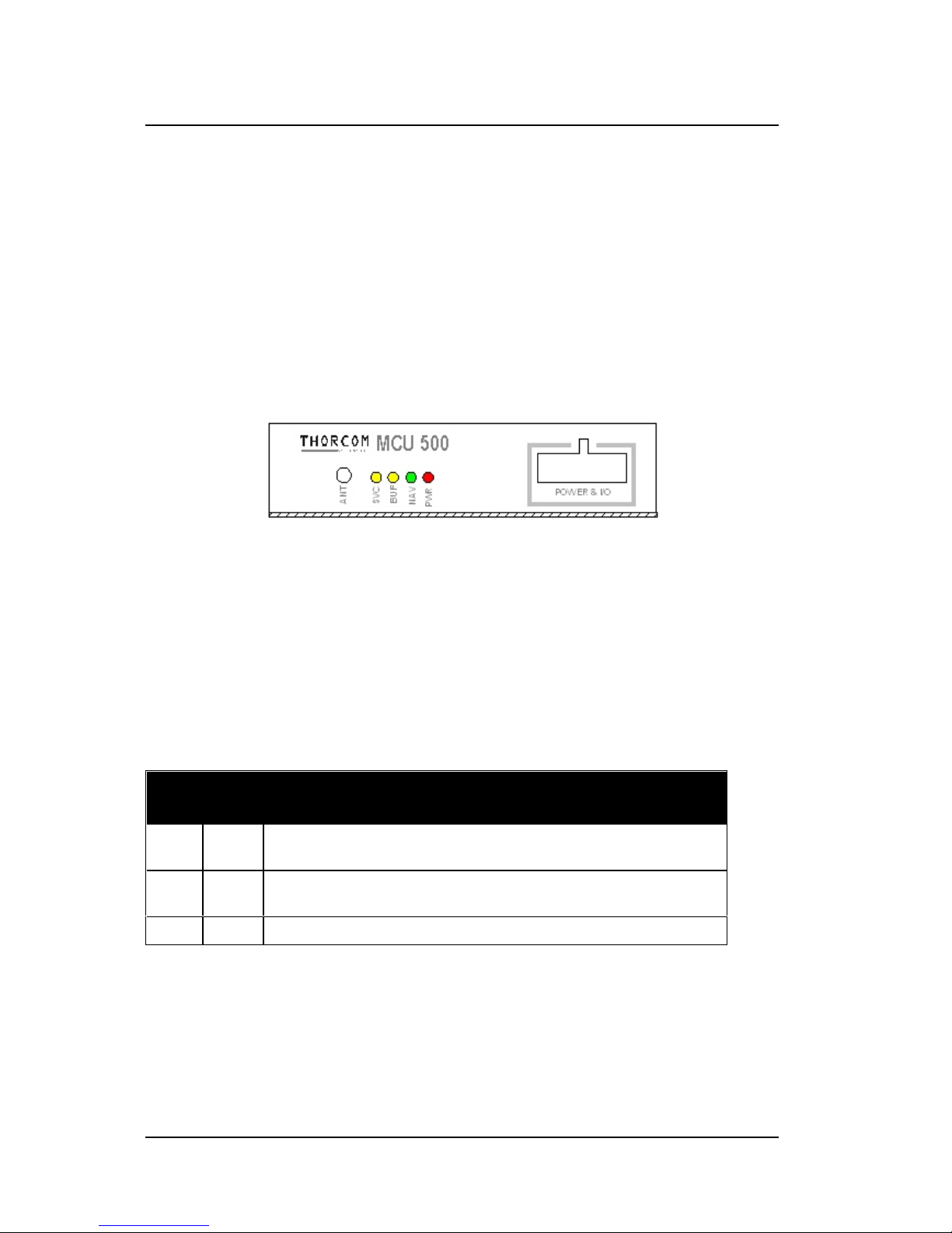
The front panel has the 12-way Molex connector for power and I/O, the GPS
antenna RF connector and four status LEDs.The rear panel has the two 9-way Dtypes for the serial ports COM1 and COM2 and an RJ45 connector for the
auxillary port.
2.4.1 Front panel layout
The front panel of the MCU500 is shown below:
2.4.2 Status LEDs
The MCU500 has four LEDs used for indicating the status of the locator unit as
follows:
NameColo
ur
Description
PWR Red Indicates that the power is applied to the unit and that its is switched
on
NAV Green Flashing (1 second pulses) indicates that the MCU500 is performing
position calculations
BUF Yellow Flashes briefly to indicate that a message is being sent or received
Page 12

Hardware Reference Manual MCU500 Mobile Locator/Control Unit
NameColo
ur
Description
100-00191 Revision 1.01 5
SVC Yellow Permanently lit to indicate that a good connection is made with the
radio device
Flashes to indicate that the personality programming is incorrect
2.4.3 Rear panel
Page 13

Hardware Reference Manual MCU500 Mobile Locator/Control Unit
6 Revision 1.01 100-00191
The rear panel contains two standard 9-way D-type male connectors for
connection to the radio device and for a connection to a mobile data terminal
(MDT), or engineering programming equipment. There is a central RJ45
connector which carries a third serial port (with RS232 or RS485 signal level
options), and some further digital inputs.
For most applications the mobile data terminal and/or PC is connected to COM1
and the radio bearer is connected to COM2. Consult the software reference
manual for further details.
2.5 Deep sleep timer
The MCU500 is equipped with a “deep sleep timer” which allows the unit to
conserve power but wake up periodically, determine if events have changed,
make a transmission (or transmissions)and then go back to sleep. When
sleeping, the unit draws only a few hundred micro-amps from the power source.
This permits operation from a battery, for example if the unit were to be installed
in an un-powered goods trailer.
The wake up period is configurable using a jumper on the PCB. Please note that
not all versions of firmware support use of the deep sleep timer - please consult
Thorcom for additional advice.
2.6 Application firmware
The MCU500 hardware can be used to run several different sets of firmware for
different applications including:
• MPT1327 Trunked radio systems with MAP27 enabled mobile radios
• TETRA digital radio systems which comply with the ETS 300.392-5 PEI
specification
• Digital Cellular systems using GSM AT+C Cellular extensions
The MCU500 hardware is essentially generic and the firmware installed sets the
application/use. It is important to have the correct firmware, documentation and
programming utilities for your application.
Page 14
Hardware Reference Manual MCU500 Mobile Locator/Control Unit
100-00191 Revision 1.01 7
3. Installation and operation
3.1 Installation
The locator unit is designed for installation in the vehicle in a convenient location,
for example under the passenger seat, in the boot or behind a bulk-head.
The MCU500 may be operated in any orientation. The front and rear panels have
fixing holes to permit the unit to be fixed to a flat surface. Sufficient room
(approximately 75-80mm) should be left to allow access the connectors on the
front/rear panels.
3.2 Power connection
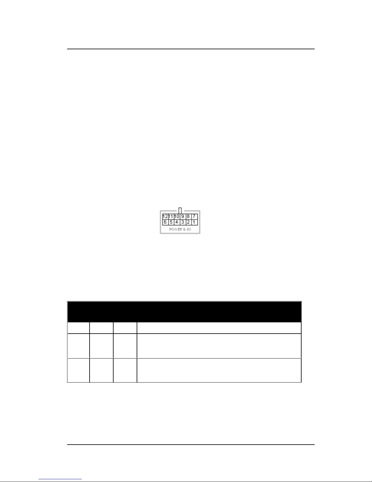
The following diagram shows the MCU500 power and I/O connector when
viewed from outside the MCU500
The power supply to the unit is provided via the 12-way Molex connector (Molex
part number 39-01-2120) on the front panel.
Thorcom cable (part number 70-00169) for power supply only is available with
three pins pre-wired with 3m long leads as follows:
Pin NameColo
ur
Description
1 GND Black Ground: connect to a suitable negative supply point
2 VIN Red Power input: normally connected to an un-switched
(permanent) source of +12V (or +24V dep ending on model).
The power lead should be fused (1A fuse) close to the source.
3 IGN Yellow Ignition sense: a voltage of more th an 3V ca uses the unit to
switch on - the unit switches off under software control at the
appr opriate tim e
If the unit is to be supplied from a switched power source then the red and yellow
lines should be joined together and connected to the switched source. Note that
in this configuration not all of the features of the unit will be available.
Note: The relays fitted to the MCU500 are capable of switching a maximum of 10
Page 15

Hardware Reference Manual MCU500 Mobile Locator/Control Unit
8 Revision 1.01 100-00191
Amps. Ensure that the cable ratings selected match the switched current.
See section 4 for the complete description of the pin-outs of the remaining pins
on the Molex connector
3.3 Connection to radio communications equipment
In the vast majority of cases the radio communications equipment will present a
standard 9-way female (DB9F) connector, or will have a special cable which ends
in a standard 9-way female connector. Where the radio has a standard 9-way
connector, a standard RS232 cable (male to female - straight through) can be
used to connect COM2 of the MCU500 to the radio device. Thorcom can supply
this cable if required, Thorcom part number 70-00167.
If the manufacturer of the radio device provides a special cable from the radio
transceiver to a PC/laptop serial port, this cable can probably be used with the
MCU500. (The 9-way ports on the MCU500 are pin-compatible with standard PC
serial COM ports).
Please consult sections 4 and 8 regarding pinouts of the connector and jumper
settings and/or contact Thorcom for availability of ready made connectors.
3.4 GPS antenna selection
The MCU500 has an SMB RF connector on the front panel for connection to a
GPS antenna. The GPS receiver is qualified for use with three antennas supplied
by Thorcom. Other GPS antennas may be used (see 3.4.2 for technical
requirements).
3.4.1 Standard GPS antennas
A range of GPS antennas are available from Thorcom, these are manufactured
by Trimble and have been formally qualified for use with the GPS receiver
module inside the MCU500.
Type Description Part No.
Hard
mount
Antenna for permanent installation on the roof of a vehicle or
other flat/horizontal surface. Requires single 18mm hole. TNC
RF connector. Requires separate RF cable to radio modem (see
table below).
50-00001
Page 16

Hardware Reference Manual MCU500 Mobile Locator/Control Unit
Type Description Part No.
100-00191 Revision 1.01 9
Mag mount Magnetic mount antenna for temporary use on a vehicle.
Suppled with integral 5m long RG174 RF cable and SMB plug
for connection to the radio modem.
50-00002
The Hard Mount antenna is most frequently used in permanent vehicle
installations - this antenna has a TNC RF socket and requires a separate cable
to connect it to the MCU500. The following cables are available:
Part
Number
Description
70-00103 TNC to SMB, RG188 PTFE co-axial
cable, 2m long
70-00122 TNC to SMB, RG188 PTFE co-axial
cable, 5m long
Other lengths are available to special order - please enquire.
3.4.2 Alternative GPS antennas
A wide range of GPS antennas are available on the market, some of which may
be used with the MCU500. The MCU500's internal GPS receiver module requires
a standard antenna on the GPS L1 frequency (1575.42MHz) with an active preamplifier with 26dB gain powered from 5V DC from the cable. A “passive”
antenna cannot be used with the MCU500.
The antenna should draw approximately 20-50mA in order that the internal
“antenna fault” alarm is not operated. Low loss (small diameter) cable (RG174 or
RG188) may be used up to 5m long. The cable should be terminated in an SMB
50ohm plug for connection to the MCU500.
Several companies, for example Panorama Antennas Limited
(http://www.panorama.co.uk), manufacture dual-band combined antennas for
operation as GPS+GSM and GPS+TETRA. These antennas have been found to
work with the MCU500 and can be ordered with the correct connectors fitted.
Panorma Part
Number
Description
GPSK-SMB-S2-5B GPS Kombi TETRA 410-430 MHz 6m GPS cable with SMB fitted, 5m
TETRA cable BNC fitted
GPSK-SMBP-DE-5F GPS Kom bi 800/900/1800/1900 6m GPS cable with SMB fitted, 5m
Cellular cable FME fitted
Page 17

Hardware Reference Manual MCU500 Mobile Locator/Control Unit
Panorma Part
Number
Description
10 Revision 1.01 100-00191
GPSM-SMBP GPS only mag-mount, 6m cable, SMB fitted
GPSP-SMBP GPS only panel mount 6m cable, SMB fitted
Page 18

Hardware Reference Manual MCU500 Mobile Locator/Control Unit
100-00191 Revision 1.01 11
4. Interfaces and connectors
The MCU500 has a total of five external connectors as follows:
Port Connector Usage
Power &
I/O
12-way Molex
multi-pole
Connection of power, ignition control, digital inputs and
outoputs
COM1 9-way D-type
male
Serial comm unication s por t for c onne ction of op tional mobile
data terminal (MDT), computer (PC) or personal organiser
(PDA) device
COM2 9-way D-type
male
Serial comm unication s por t for c onne ction of ra dio
communications network device
AUX 8-way RJ45
socket
Auxiliary connector for RS485 serial port, analogue input and
additional digital inp uts
GPS SMB RF socket Antenna connector to the internal GPS receiver
4.1 Power and input/outputs
This connector is a 12-way Molex connector and provides connections for power,
ignition sense, digital inputs and relay outputs at follows:
PinNam
e
Description
1 GND Ground connection (negative)
2 VIN Un-switched power supply input (12V or 24V
depe nding on model)
3 IGN Ignition sense input (voltage above 3V causes the
unit to switch on)
4 IN1 Input 1 - ground to operate
5 IN2 Inpu t 2 - ground to operate
6 IN3 Inpu t 3 - ground to operate
7 RL1NORelay 1 - normally open contact
8 RL1COMRelay 1 - common contact
9 RL1NCRelay 1 - normally closed contact
10 RL2NORelay 2 - normally open contact
Page 19

Hardware Reference Manual MCU500 Mobile Locator/Control Unit
PinNam
e
Description
12 Revision 1.01 100-00191
11 RL2COMRelay 2 - common contact
12 RL2NCRelay 2 - normally closed contact
The standard power lead provided with MCU500 has the first three pins wired.
The Molex receptacle, part number 39-01-2120, mates with the MCU500 and
additional crimp contacts can be used to wire the additional connections (use
Molex part number 39-00-0039 for 3A connections).
4.2 COM1serial port
The primary serial port (COM1) is provided on a standard DB9 male connector,
configured as a DTE with a pin-out which is compatible with an IBM PC/AT serial
port:
PinNa
me
Description
1 DCD Data Carrier Detect
(input)
2 RXD Receive Data (inpu t)
3 TXD Trans mit Data (output)
4 DTR Data Terminal Ready
(output)
5 GND Ground
6 N/C No connection
7 RTS Request To Send
(output)
8 CTS Clea r To Send (input)
9 N/C No connection
The primary serial port (COM1) operates at standard RS232/CCITT V.24 voltage
levels and is intended for the connection of a mobile data terminal, in vehicle PC
or similar. This primary serial port is also used for programming the unit. A 9-way
female to 9-way female (cross-over) cable is needed to connect MCU500 to
COM port on a PC. Use Thorcom cable 70-00168 or similar.
Page 20

Hardware Reference Manual MCU500 Mobile Locator/Control Unit
100-00191 Revision 1.01 13
4.3 COM2 serial port
The secondary serial port (COM2) is provided on a standard DB9 male
connector, configured as a DTE with a pin-out which is compatible with an IBM
PC/AT serial port:
PinNa
me
Descript ion
1 DCDData Carrier Detect
(input)
2 RXDReceive Data (input)
3 TXD Transm it Data (output)
4 DTRData Terminal Ready
(output)
5 GNDGround
6 N/C No connection
7 RTS Request To Send
(output)
8 CTS Clear To Sen d (input)
9 MBUSNokia Message Bus
(MBUS)
The secondary serial port operates at standard RS232/CCITT V.24 voltage
levels, TTL/CMOS 5V levels or inverted TTL/CMOS levels, selected by internal
jumpers. This allows the communications port to be used with a wide range of
data communications providers/devices including those with TTL/CMOS voltage
levels.
In addition to these signal levels it is possible to configure the secondary serial
port to work with the Nokia Message Bus (MBUS) protocol used on many of
Nokia’s GSM mobile phones and Tetra radios.
WARNING: due to the nature of the secondary channel’s ability to switch
between TTL/CMOS and RS232 levels it is possible to connect an RS232 device
to the MCU500 while it is configured for TTL/CMOS input/output - this may
damage the unit. Do not change the port settings fronm the factory default
(RS232) unless you are sure that the voltage levels are correct for both devices.
4.4 Auxiliary port
Page 21

Hardware Reference Manual MCU500 Mobile Locator/Control Unit
14 Revision 1.01 100-00191
The AUX port is a standard 8-way RJ45 socket which provides a third RS232 or
RS485 serial port and access to a number of other inputs and outputs:
Pi
n
Name Description
1 IN4/AO1 Digital input #4 or auxiliary output #1 (jumper selectable)
2 IN5/AO2 Digital input #4 or auxiliary output #1 (jumper selectable)
3 BUSB+ COM3 RS485 port TxD
4 BUSA+ COM3 either RS232 TxD or RS485 port RxD (jumper
selectable)
5 BUSB- COM3 RS485 port TxD
6 BUSA- COM3 either RS232 RxD or RS485 port RxD (jumper
selectable)
7 IN6/RTCM Digital input #6 or RTCM-SC104 RS232 differential correction
data input to GPS receiver (jumper selectable)
8 GND Ground
Notes:
1. The RS485 port may be operated in half-duplex or full-duplex mode
2. The RS485 convertor may be disabled and direct connections made using
RS232 logic levels
3. Pin 7 may be used to provide differential correction data using standard
RTCM-SC104 at 4800bps with standard RS2332 voltage levels
WARNING: due to the nature of the Aux port’s serial channel it is possible to
configure it for TTL/CMOS operation - do not connect RS232/V.24 signals to this
port as this may cause damage to the CPU.
4.5 GPS antenna connector
The GPS antenna connector is a 50 ohm SMB RF socket. Connect a suitable
26dB gain active GPS antenna to this connecor.
See section 3.4 for information on appropriate antennas.
Page 22

Hardware Reference Manual MCU500 Mobile Locator/Control Unit
100-00191 Revision 1.01 15
5. Maintenance and trouble shooting
The MCU500 is not designed to be serviced in the field in respect of component
replacement and fault finding, however the following notes may be of use.
5.1 Removing the PCB from the case
The PCB may need to be removed from the case to alter a jumper setting or
change the firmware EPROM/FLASH device. Use the following procedure:
a. disconnect the GPS antenna and power connector from the front of the
unit.
b. undo and remove the nut on the SMB connector (front panel).
c. undo and remove the four corner screws on the rear panel.
d. slide out the PCB (the rear panel will remain attached). Take care to save
the small washer fitted behind the GPS connector internally, and replace
when reassembling.
To re-assemble the MCU500 follow the same procedures in the reverse order.
Do NOT overtighten the GPS antenna nut, finger tight plus ½ turn is sufficient.
Over tightening may damage the GPS connector assembly.
WARNING: The MCU500 uses CMOS devices which are sensitive to ESD. Take
appropriate precautions, for example using a conductive bench and earthed wrist
strap.
5.2 Changing the firmware EPROM/FLASH device
In order to change the EPROM/FLASH device
a. Remove the modem PCB from the case as described in section 6.1
(above).
b. Locate the dual in line EPROM/FLASH device at position IC3.
c. Using an IC extractor tool remove the IC from the socket.
WARNING: never use a screwdriver to “lever” the IC from the socket as it
is possible to damage the PCB tracks under the socket.
d. Fit the new EPROM/FLASH in the socket. If the device has 28 pins then it
should be fitted nearest the edge of the PCB so that the spare holes of the
Page 23

Hardware Reference Manual MCU500 Mobile Locator/Control Unit
16 Revision 1.01 100-00191
socket are nearest the middle of the PCB.
e. Check the settings of jumper JP5 for the correct size/type of device.
g. Re-assemble the case.
5.3 Trouble shooting
The following notes are provided to aid trouble shooting and should be read in
conjunction with the software/firmware documentation.
5.3.1 No response from the MCU500
Is the PWR (power on) LED lit? If not check that:
a) that the power cable is connected
b) that the power supply is present (eg. fuse not blown)
c) that the ignition sense line goes on (mor than 3V) to power up the unit
If the PWR LED is lit check that:
d) the cable between the MCU500 and radio/transceiver device is attached
5.3.2 Unit unable to send location updates
Check that the GPS antenna is plugged in. Check that after approximately 20
seconds from turning the power on that the NAV (Naviating) LED flashes on/off
once per second.
If the NAV light remains off then there is a problem with the GPS antenna cable
or the antenna itself - replace and re-test.
If the unit has been unused for an extended period (several weeks) the almanac
data may not be valid which will cause the unit to wait to download a new version
of the system almanac. Almanac download takes approximately 12.5-15 minutes
to achieve given good coverage (view to the sky). This situation may occur when
first installing MCU500 units into vehicles.
5.3.3 Unit not correctly programmed
The MCU500 stores user configuration (its personality) in non-volatile memory.
The configuration must be valid for the unit to function correctly. If, at power up,
the unit’s configuration is found to be incorrect (ie. missing or corrupt) the SVC
led flashes indicating that the unit requires programming.
Page 24

Hardware Reference Manual MCU500 Mobile Locator/Control Unit
100-00191 Revision 1.01 17
The user configuration (personality) is programmed using the Modem Personality
Programmer (MPP) software.
Page 25
Hardware Reference Manual MCU500 Mobile Locator/Control Unit
18 Revision 1.01 100-00191
6. Jumpers and configuration options
The MCU500 has a number of push on jumpers which configure operation of the
unit. The jumpers and settings vary according to the use of the unit and the
make/model of radio transceiver/communcations device which it is connected to.
Please refer to the release notes/documentation for the specific application
firmware to ensure that the jumpers and adjustments are set correctly for your
application.
The MCU500 has the following user selectable jumpers:
Jump
er
Name Description
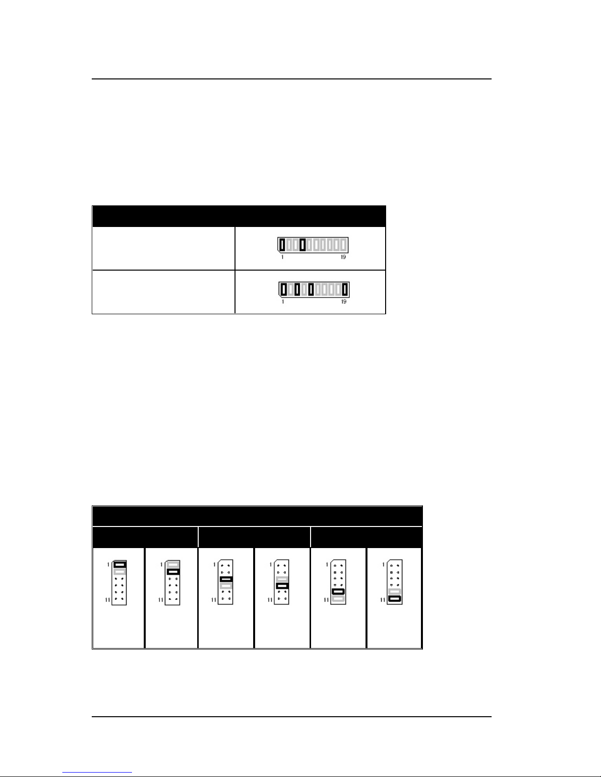
JP3 COM 2 Settings Select the voltage levels of COM2 between RS232, TTL and
Inverted TTL
JP4 Input 2 Mode Select Select betwee n analog ue or digital se nse on input 2
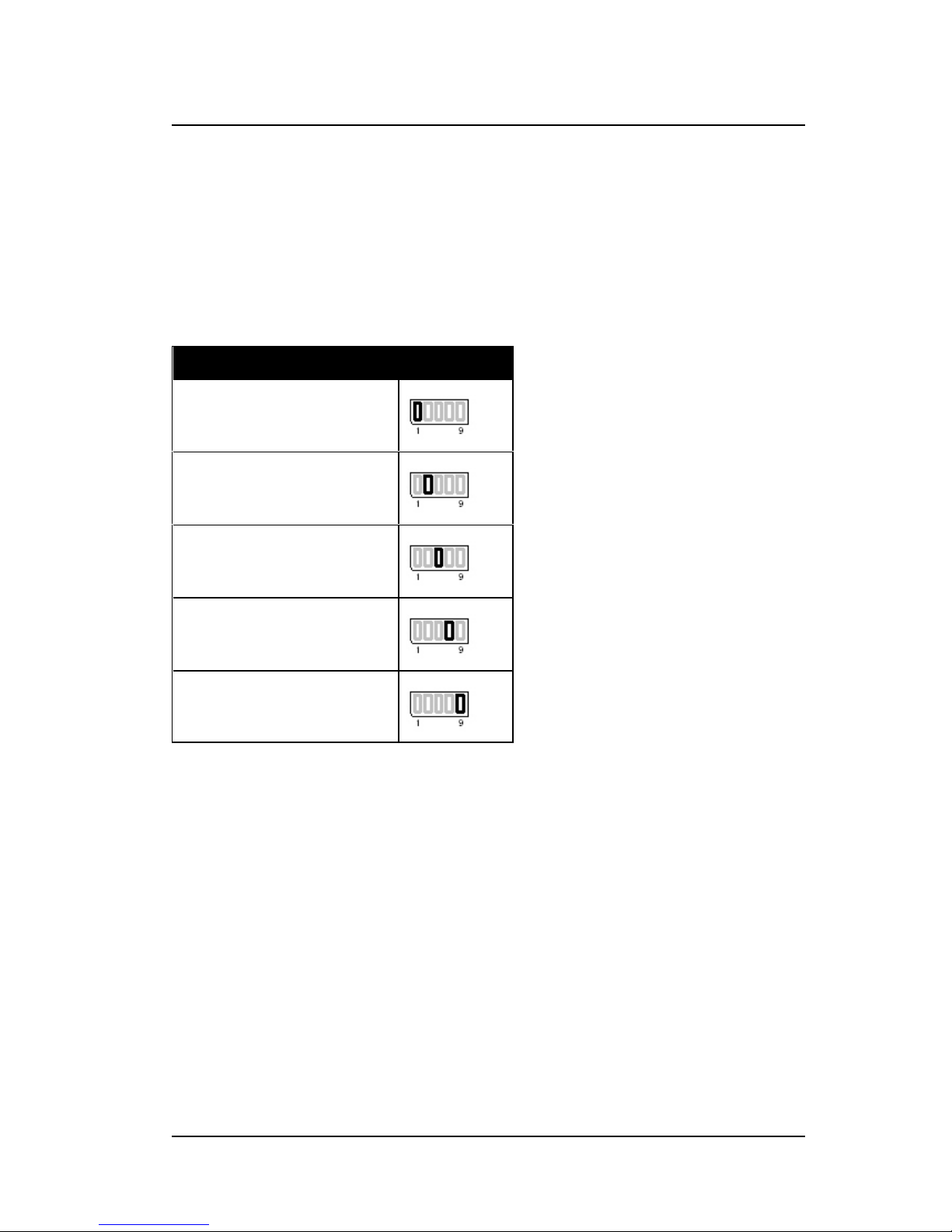
JP5 EPROM Settings Select EPROM size and between Standard EPROM or
FLASH EPROM
JP6 RJ45 Mode Select Select the I/O mode of the auxiliary pins on the RJ45
connector
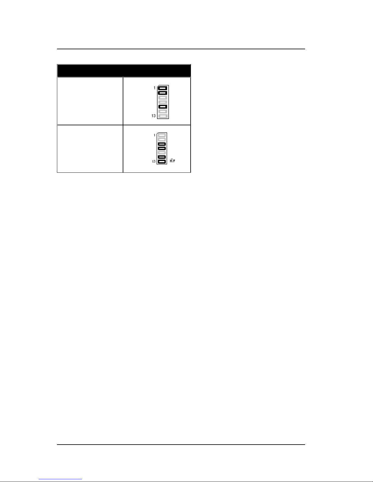
JP7 Timer Settings Select the time period between hardware timer wake-up
events
JP8 COM 3 Settings Select the voltage levels and bus style between RS232 and
RS485
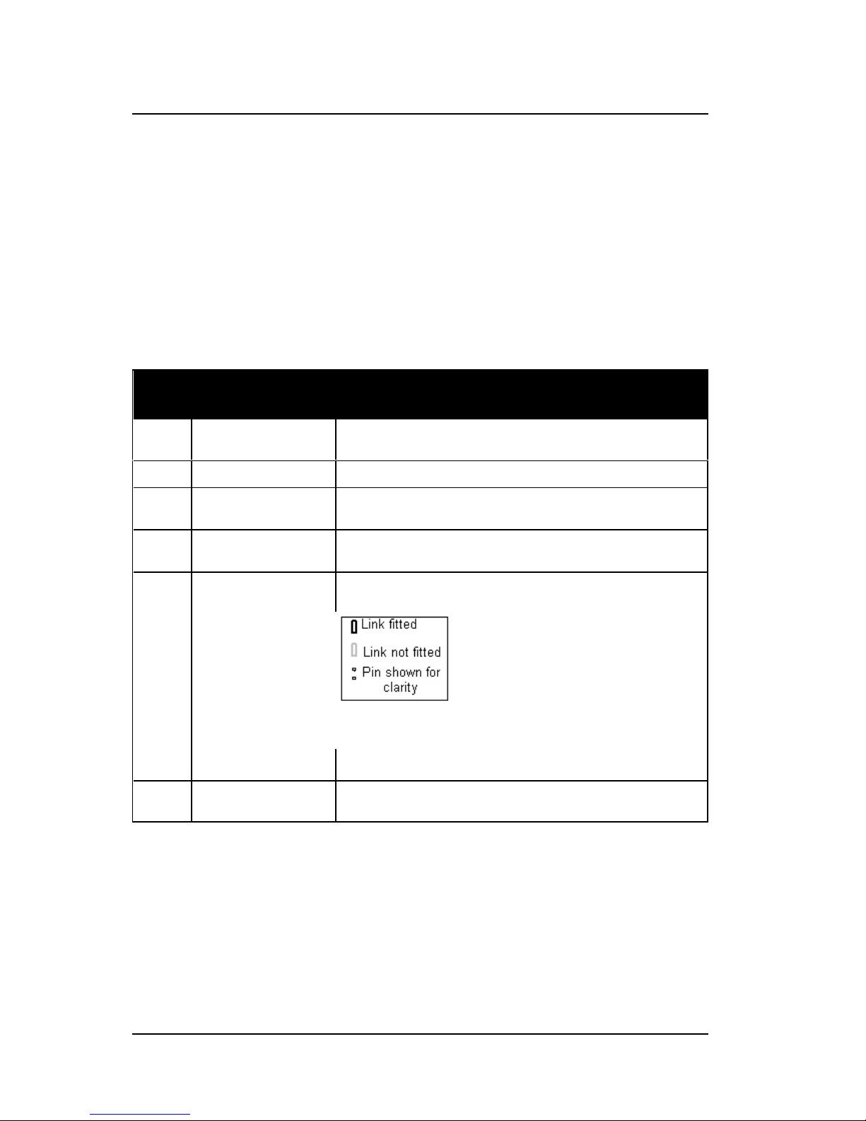
In subsequent link drawings, the following colour scheme is used :
6.1 COM2 voltage settings
The second serial port (COM2 of the MCU500) is used as the interface to the
Page 26
Hardware Reference Manual MCU500 Mobile Locator/Control Unit
100-00191 Revision 1.01 19
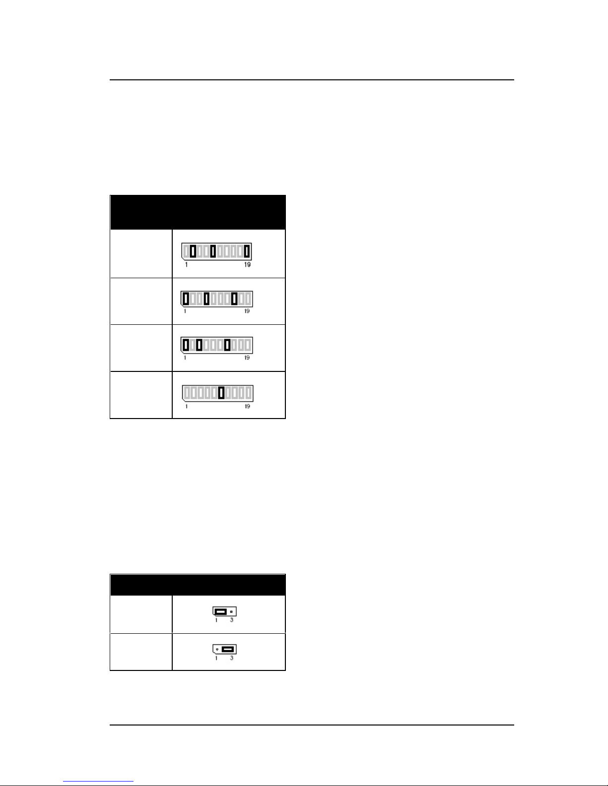
radio transceiver. This port can be configured for operation as RS232, TTL logic
level, inverted TTL logic or Nokia MBUS using jumper JP3.
With the MCU500 unboxed, and orientated so that the GPS connector is on the
right-hand side, JP3 can be found running horizontally in the bottom left-hand
corner of the PCB.
Voltage
Level
JP3
RS232
TTL
Inverted
TTL
Nokia
MBus
6.2 Analogue input/mode selection
For MCU500 units that have been manufactured with an analogue input
capability, JP4 configures whether input 2 (Ppn 5 of the Molex connector) is a
standard digital input, or an analogue input.
With the MCU500 unboxed, and orientated so that the GPS connector is on the
right-hand side, JP4 can be found running horizontally just to the left of the Molex
connector.
Input 2 JP4
Analogue
Digital
6.3 EPROM/FLASH size and type
Page 27
Hardware Reference Manual MCU500 Mobile Locator/Control Unit
20 Revision 1.01 100-00191
Most MCU500 units will contain FLASH memory, and these settings will not need
to be changed. For users wishing to upgrade to FLASH, these jumpers must be
changed at the same time that the EPROM is changed.
With the MCU500 unboxed, and orientated so that the GPS connector is on the
right-hand side, JP5 can be found running horizontally just above the EPROM
socket (IC3), and to the right of the lithium battery.
EPROM JP5
27C512 EPROM or
27E512 EEPROM 64K
29F040 FLASH EPROM
6.4 RJ45 pin assignments
The MCU500 has more I/O capability than actual physical connections, and so to
remain as flexible as possible it is possible to change the mode of some of the
pins on the RJ45 connector to match specific application requirements.
The table below shows each RJ45 connection separately, each option can be
used in parallel, with up to 3 jumpers fitted in total.
With the MCU500 unboxed, and orientated so that the GPS connector is on the
right-hand side, JP6 can be found running vertically just to the right of the RJ45
connector.
JP6
RJ45 Pin 1 RJ45 Pin 2 RJ45 Pin 7
Input 4 Aux Out1Input 5 Aux Out2Input 6 RTCM In
6.5 Hardware wake-up timer
Page 28
Hardware Reference Manual MCU500 Mobile Locator/Control Unit
100-00191 Revision 1.01 21
The MCU500 can put itself into deep sleep to conserve power, which is
especially useful when running for extended periods on a battery only basis. The
MCU500 has the option of running an ultra-low power hardware timer to trigger
periodic wake-ups and AVL events.
With the MCU500 unboxed, and orientated so that the GPS connector is on the
right-hand side, JP7 can be found running horizontally along the top left-hand
side of the PCB.
Time Interval JP7
2.5 Hours
5 Hours
10 Hours
20 Hours
40 Hours
6.6 COM3 RS232/RS485 settings
The MCU500 has a third serial port, that can be used as a three-wire RS232
circuit (TXD/RXD/GND) or as a half-duplex or full-duplex RS485 serial bus
connection to other in-vehicle devices. Operation is selected via JP8.
With the MCU500 unboxed, and orientated so that the GPS connector is on the
right-hand side, JP8 can be found running vertically to the left of the EPROM
(IC3), below the lithium battery.
Page 29
Hardware Reference Manual MCU500 Mobile Locator/Control Unit
22 Revision 1.01 100-00191
COM3 Levels JP8
RJ45 is RS232
RJ45 is RS485 Full
Duplex
Note: Link 13/14 is effectively a half/full duplex selector
Page 30

Hardware Reference Manual MCU500 Mobile Locator/Control Unit
100-00191 Revision 1.01 23
7. Technical specifications
CPU: Zilog Z80182 at 29.4912MHz
Memory: 128Kb or 512Kb Static RAM with battery
backup
32Kb-512Kb EPROM or FLASH
(firmware/software)
2Kb serial I2C non-volatile RAM (factory and
user settings)
Status indicators: 4 LEDs for status indication
Serial ports: COM1: 9-way D-type male, configured as
PC/AT compatible port with TXD, RXD, RTS,
CTS, DCD, DTR, and GND
COM2: 9-way D-type male, configured as
PC/AT compatible port with TXD, RXD, RTS,
CTS, DCD, DTR, and GND. Voltage selectable
between RS232, TTL, Inverted TTL and Nokia
M bus
COM3: RJ45 with RS232 TXD and RXD only,
or half/full duplex RS485
Internal GPS receiver: Trimble ACE-III, with RTCM SC104
differential input capability
Digital inputs: Six inputs: internally pulled up to +5V via
10K, ground to operate, over/under
voltage protected
Relay outputs: Two relays: Single Pole Change Over
(SPCO) rated at 10A (resistive) 5A
(inductive)
Power supply: 12V model (10.0 to 16.0 volts DC input)
24V model (20.0 to 32.0 volts DC input)
High efficiency switched mode, software
controllable.
Power consumption: 1.5 watts (GPS receiver installed) - 12V
version
Size: 194mm (D) x 108mm (W) x 33mm (H)
excluding connectors
Page 31

Hardware Reference Manual MCU500 Mobile Locator/Control Unit
24 Revision 1.01 100-00191
Environmental: Enclosure to IP54
Operating temperature: -10 to +55 Celsius
Storage temperature: -20 to +70 Celsius
Humidity: 0-90% (non-condensing)
Mean Time Between Failure (MTBF): 70,000 Power On Hours (POH)
calculated to MIL-217E
Errors and omissions accepted. Thorcom Systems Limited reserves the right to amend or alter the
specification of this product in line with its policy of con tinued development and improv ement.
Page 32

Hardware Reference Manual MCU500 Mobile Locator/Control Unit
100-00191 Revision 1.01 25
7.1 Electro-magnetic compatibility and electrical safety
The MCU500 modem has been tested for EMC compliance to:
EN 55022
ETS 300-279
Connections to the MCU500 shall be less than 3.0m in length.
The MCU500 complies with the protection requirements of the EMC directive
89/336/EEC providing that it is installed, operated and maintained as specified.
The MCU500 modem also meets the requirements of the Low Voltage Directive
(EC/73/23).
Full test results for the MCU500 are held by Thorcom Systems Limited and EMC
compliance certificates are available on request.
 Loading...