

Thor Broadcast H-IPRF-16QAM User Manual

Thor Fiber 2016 Tel: (800) 521-8467 Email: sales@thorfiber.com http://www.thorbroadcast.com
User Manua
l
H-IPRF-16QAM
Revision 2017

H-IPRF-16QAM
Thor Fiber 2016 Tel: (800) 521-8467 Email: sales@thorfiber.com http://www.thorbroadcast.com
A Note from Thor Broadcast about this Manual
Intended Audience
This user manual has been written to help people who have to use, integrate and to install the product. Some
chapters require some prerequisite knowledge in electronics and especially in broadcast technologies and
standards.
Disclaimer
No part of this document may be reproduced in any form without the written permission of Thor Broadcast.
The contents of this document are subject to revision without notice due to continued progress in methodology,
design and manufacturing. Thor shall have no liability for any error or damage of any kind resulting from the
use of this document.
Copy Warning
This document includes some confidential information. Its usage is limited to the owners of the product
that it is relevant to. It cannot be copied, modified, or translated in another language without prior written
authorization from Thor Broadcast.

H-IPRF-16QAM
Thor Fiber 2016 Tel: (800) 521-8467 Email: sales@thorfiber.com http://www.thorbroadcast.com
Table of Contents
CHAPTER 1 PRODUCT OVERVIEW .................................................................................................................. 1
1.1 OUTLINE .................................................................................................................................................. 1
1.2 KEY FEATURES .......................................................................................................................................... 1
1.3 GENERAL MAPPING ................................................................................................................................. 2
1.4 CARRIER SETTING ILLUSTRATION ............................................................................................................. 2
1.5 SPECIFICATIONS ....................................................................................................................................... 3
CHAPTER 2 - APPEARANCE............................................................................................................................. 4
2.1 FRONTAL VIEW: ....................................................................................................................................... 4
2.2 REAR PANEL ILLUSTRATION: ..................................................................................................................... 4
CHAPTER 3 INSTALLATION GUIDE .................................................................................................................. 5
3.1 IN THE BOX .............................................................................................................................................. 5
3.2 INSTALLATION PREPARATION ................................................................................................................... 5
3.2.1 DEVICE’S INSTALLATION FLOW CHART ILLUSTRATED AS FOLLOWS: .................................................... 5
3.2.2 ENVIRONMENT ..................................................................................................................................... 6
3.2.3 GROUNDING ......................................................................................................................................... 7
CHAPTER 4 WEB NMS MANAGEMENT ........................................................................................................... 8
4.1 LOGIN ...................................................................................................................................................... 8
4.2 OPERATION .............................................................................................................................................. 9
4.2.1 SUMMARY ............................................................................................................................................ 9
4.2.2 PARAMETERS ........................................................................................................................................ 9
CHAPTER 5 - TROUBLESHOOTING ................................................................................................................ 19
CHAPTER 6 PACKING LIST ......................................................................................................................... 20

H-IPRF-16QAM
Thor Fiber 2016 Tel: (800) 521-8467 Email: sales@thorfiber.com http://www.thorbroadcast.com
Chapter 1 Product Overview
1.1 Outline
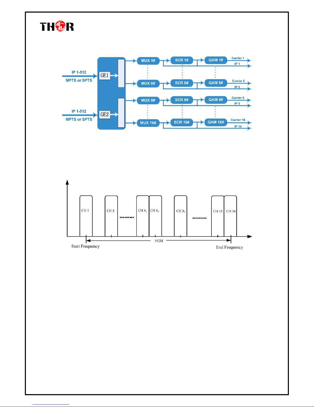
The Thor Broadcast new Edge QAM Modulator is a new 1 RU chassis headend in a box that will
ingest IP feeds and convert to a QAM channel lineup of your choosing. The latest gen unit has an
inclusive chassis that no longer uses blades but does all necessary functioning preloaded to
successfully convert IP streams to 16 (or 32- model dependent) QAM channels to create your own
efficient IPTV headend into an RF headend. This powerhouse will scramble, multiplex, and modulate
up to 16 or 32 channels that supports a maximum 1024 IP TS streams through the 2 GE ports and
output 16 or 32 non-adjacent carriers (50MHz~960MHz) via the single RF output interface on the
rear of the unit. High performance encoding means you can now distribute countless channels into
the bandwidth of 16 QAM carriers.
1.2 Key Features
2 GE input, SFP interface
Supports up to 1024 channels TS over UDP/RTP, unicast and multicast, IGMP v2\v3
Max 840Mbps for each GE input
Accurate PCR adjusting
CA PID filtering, remapping and PSI/SI editing
Up to 180 PIDS remapping per channel
DVB general scrambling system (ETR289), simulcrypt standards ETSI 101 197 and ETSI 103 197
16 multiplexed or scrambled TS over UDP/RTP/RTSP output
16 non-adjacent QAM carriers output, compliant to DVB-C (EN 300 429) and ITU-T J.83 A/B
RS (204,188) encoding
NMS Web-based Network management
H-IPRF-16QAM
Thor Fiber 2016 Tel: (800) 521-8467 Email: sales@thorfiber.com http://www.thorbroadcast.com
1.3 General Mapping
1.4 Carrier Setting Illustration

H-IPRF-16QAM
Thor Fiber 2016 Tel: (800) 521-8467 Email: sales@thorfiber.com http://www.thorbroadcast.com
1.5 Specifications
Input
Input
512×2 IP input, 2 100/1000M Ethernet Port (SFP)
Transport Protocol
TS over UDP/RTP, unicast and multicast, IGMP
V2/V3
Transmission Rate
Max 840Mbps for each GE input
Mux
Input Channel
1024
Output Channel
16
Max PIDs
180 per channel
Functions
PID remapping(auto/manually optional)
PCR accurate adjusting
PSI/SI table automatically generating
Scrambling
Parameters
Max simulscrypt CA
4
Scramble Standard
ETR289, ETSI 101 197, ETSI 103 197
Connection
Local/remote connection
Modulation
Parameters
QAM Channel
16 non-adjacent carriers
Modulation Standard
EN300 429/ITU-T J.83A/B
Symbol Rate
5.0~7.0Msps, 1ksps stepping
Constellation
16, 32, 64, 128, 256QAM
FEC
RS (204, 188)
RF Output
Interface
1 F-type output port for 16 carriers, 75Ω
RF Range
50~960MHz, 1kHz stepping
Output Level
-20dBm~+10dBm(87~117dbµV), 0.1dB stepping
MER
≥ 40dB
ACLR
-60 dBc
TS output
16 IP output over UDP/RTP/RTSP, unicast/multicast, 2 100/1000M Ethernet
Ports
System
Network management software (NMS)
General
Demission
420mm×440mm×44.5mm (WxLxH) – 1RU
Weight
3kg
Temperature
0~45℃(operation), -20~80℃(storage)
Power Supply
AC 100V±10%, 50/60Hz or AC 220V±10%,
50/60Hz
Consumption
15.4W
H-IPRF-16QAM
Thor Fiber 2016 Tel: (800) 521-8467 Email: sales@thorfiber.com http://www.thorbroadcast.com
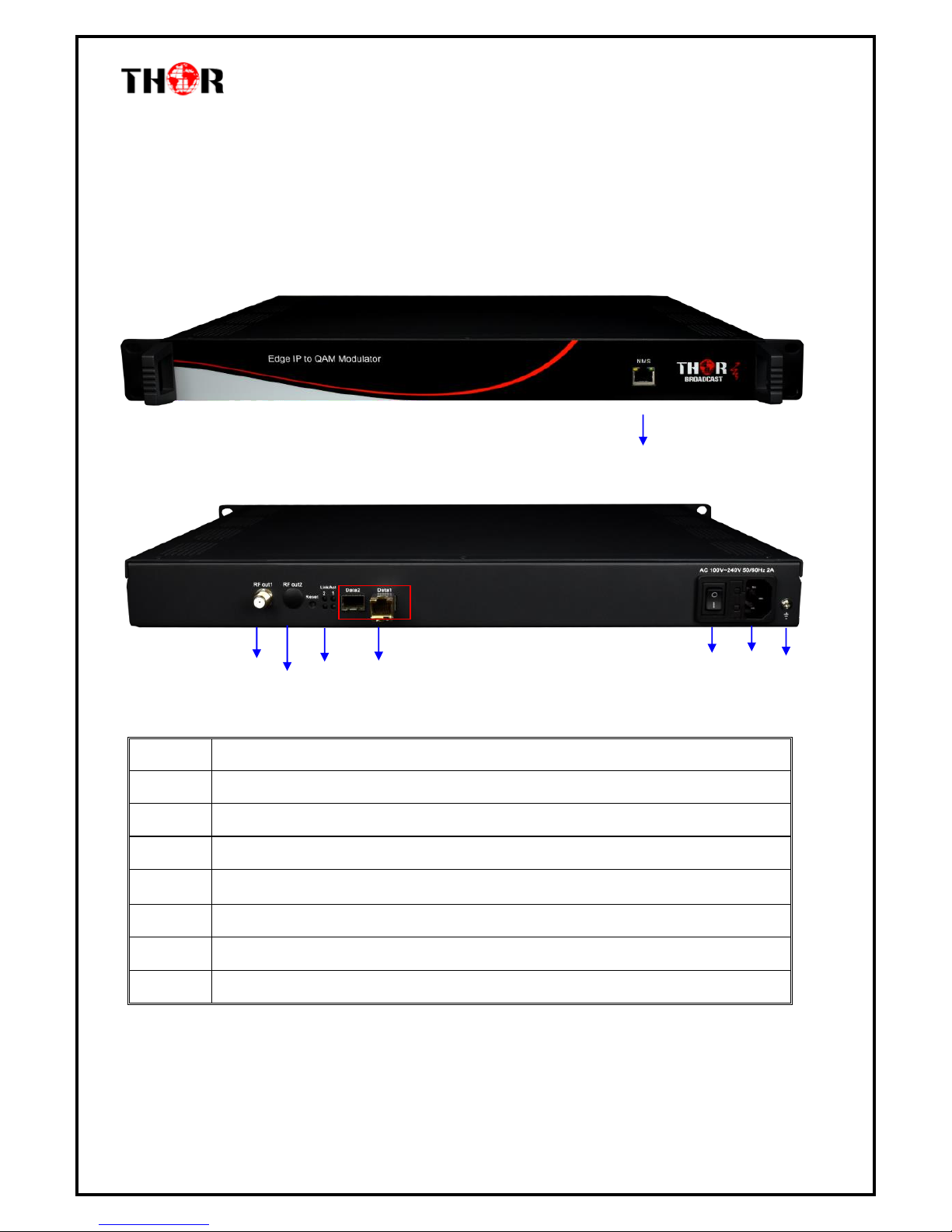
Chapter 2 - Appearance
2.1 Frontal View:
2.2 Rear Panel Illustration:
1
NMS/CAS: network management port and CA data port
2
RF output port
3
Reset IP: Reset webmaster IP address, recover to default IP address
4
Link/Act Indicators
5
Data Input/Output 1/2 (SFP)
6
Power switch
7
AC Power Socket
8
Ground
3 4 5
6
8
1
2
 Loading...