

Thor Broadcast H-8ATSC-IP User Manual
Tel: (800) 521-8467 Email: sales@thorfiber.com http://www.thorbroadcast.com
User Manual
H-8ATSC-IP Gateway

Tel: (800) 521-8467 Email: sales@thorfiber.com http://www.thorbroadcast.com
A Note from Thor Broadcast about this Manual
Intended Audience
This user manual has been written to help people who have to use, integrate and to install the product. Some
chapters require some prerequisite knowledge in electronics and especially in broadcast technologies and
standards.
Disclaimer
No part of this document may be reproduced in any form without the written permission of Thor Broadcast.
The contents of this document are subject to revision without notice due to continued progress in
methodology, design and manufacturing. Thor shall have no liability for any error or damage of any kind
resulting from the use of this document.
Copy Warning
This document includes some confidential information. Its usage is limited to the owners of the product that
it is relevant to. It cannot be copied, modified, or translated in another language without prior written
authorization from Thor Broadcast.

H-8ATSC-IP
Tel: (800) 521-8467 Email: sales@thorfiber.com http://www.thorbroadcast.com
Table of Contents
CHAPTER 1 - INTRODUCTION .............................................................................................................. 1
1.1OUTLINE ................................................................................................................................................. 1
1.2FEATURES ............................................................................................................................................... 1
1.3 SPECIFICATIONS ...................................................................................................................................... 2
1.4 PRINCIPLE CHART ................................................................................................................................... 2
1.5APPEARANCE AND DESCRIPTION .............................................................................................................. 3
CHAPTER 2 - INSTALLATION GUIDE ................................................................................................... 4
2.1 GENERAL PRECAUTIONS ........................................................................................................................... 4
2.2 POWER PRECAUTIONS .............................................................................................................................. 4
2.3 DEVICE’S INSTALLATION FLOW CHART ILLUSTRATED (AS FOLLOWING) .......................................................... 4
2.4 ENVIRONMENT ........................................................................................................................................ 5
2.5 GROUNDING REQUIREMENT ..................................................................................................................... 6
CHAPTER 3 - OPERATION ...................................................................................................................... 7
3.1 INITIALIZING .......................................................................................................................................... 7
3.2 GENERAL SETTINGS ................................................................................................................................ 7
3.2.1 ALARM STATUS.................................................................................................................................... 8
3.2.2 INPUT SETTING ................................ .................................................................................................... 8
3.2.2.1 TUNER 1 SETTING ............................................................................................................................. 8
3.2.2.1 TUNER 2-8 SETTINGS ........................................................................................................................ 8
3.2.3 OUTPUT SETTING ................................................................................................................................. 9
3.2.3.1 TUNER 1 SETTING ............................................................................................................................. 9
3.2.4 NETWORK SETTING ................................................................................................ .............................. 9
3.2.5 SAVING CONFIGURATION .................................................................................................................... 10
3.2.6 LOAD CONFIGURATION ....................................................................................................................... 10
CHAPTER 4 NMS SETTING .................................................................................................................... 11
4.1 SETUP THE NMS .................................................................................................................................... 11
4.2 NMS OPERATION .................................................................................................................................. 11
4.2.2 STATUS PAGE ..................................................................................................................................... 12
4.2.3 INPUTS PAGE ..................................................................................................................................... 13
4.2.4 MUX ................................................................................................................................................. 13
4.2.5 SPTS ................................................................................................................................................ 15
4.2.5 SYSTEM............................................................................................................................................. 17
CHAPTER 5 - TROUBLESHOOTING .................................................................................................... 19
CHAPTER 6 -PACKING LIST ................................................................................................................ 20

H-8ATSC-IP
Tel: (800) 521-8467 Email: sales@thorfiber.com http://www.thorbroadcast.com
Chapter 1 - Introduction
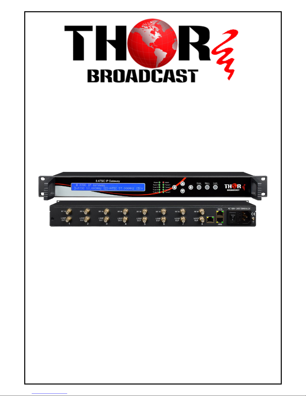
1.1Outline
The Thor Broadcast H-8ATSC-IP gateway is our new solution in converting tuner based inputs
into a Gigabit IP transport streams. This ideal head-end conversion device has massive
processing power which lets you intake up to 8 ATSC frequencies and convert to a single
Ethernet output. Thor’s new power packed deviceintegrates tuner demodulation and IP gateway
functionality, which can demodulate the signals from 8 tuners into TS and packet the TS into an
IP package, then output the IP package through different IP addresses and ports for your
convenience.Simple and sophisticated; you can now convert your off-air antenna head-end into
a modern IPTV head-end
1.2Features
High quality demodulation and gateway functions
Supports 8 channel ATSC tuners (DVB-S/S2, ISDB-T, DVB-C optional)
input and 8 IP output
MPEG-2 and MPEG-4 TS to IP one way conversion
1 GE output(support parallel 1 Gbps data output channel)
Maximum 8 tuners to IP conversion, the maximum output bit-rate is
800Mbps
UDP protocol; unicast and multicast
LCD display and keyboard
NMS operation for ease of use
H-8ATSC-IP
Tel: (800) 521-8467 Email: sales@thorfiber.com http://www.thorbroadcast.com
1.3 Specifications
Interface
Input
8 ATSC inputs (DVB-S/S2
/ISDB-T/DVB-C optional)
Output
1 GE output, TS over UDP protocol,
unicast and Multicast
Transmission Bit-rate
Maximum total bit-rate is 800Mbps
General
Dimension
(WxLxH)
482mm×410mm×44mm
Weight
3.6kg
Temperature
0~45℃(working ),
-20~80℃(storage)
Power supply
100~240VAC,50/60Hz
consumption
20W
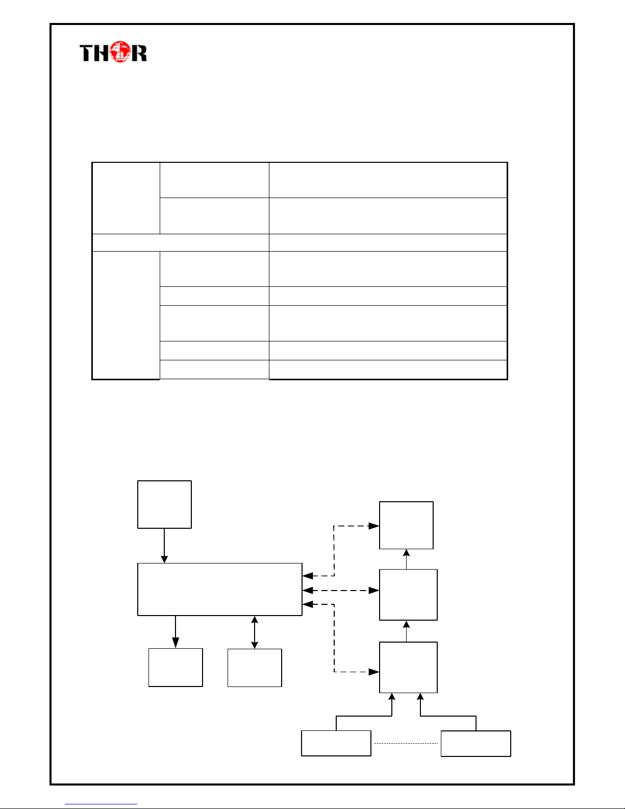
1.4 Principle Chart
Control Module
100M
Ethernet
Port
LCD
Keyboard
Gigabits
Ethernet
Port
IP
Processing
Module
Processing
Code
Stream
Tuner IN 1
Tuner IN 8
H-8ATSC-IP
Tel: (800) 521-8467 Email: sales@thorfiber.com http://www.thorbroadcast.com
1.5Appearance and Description
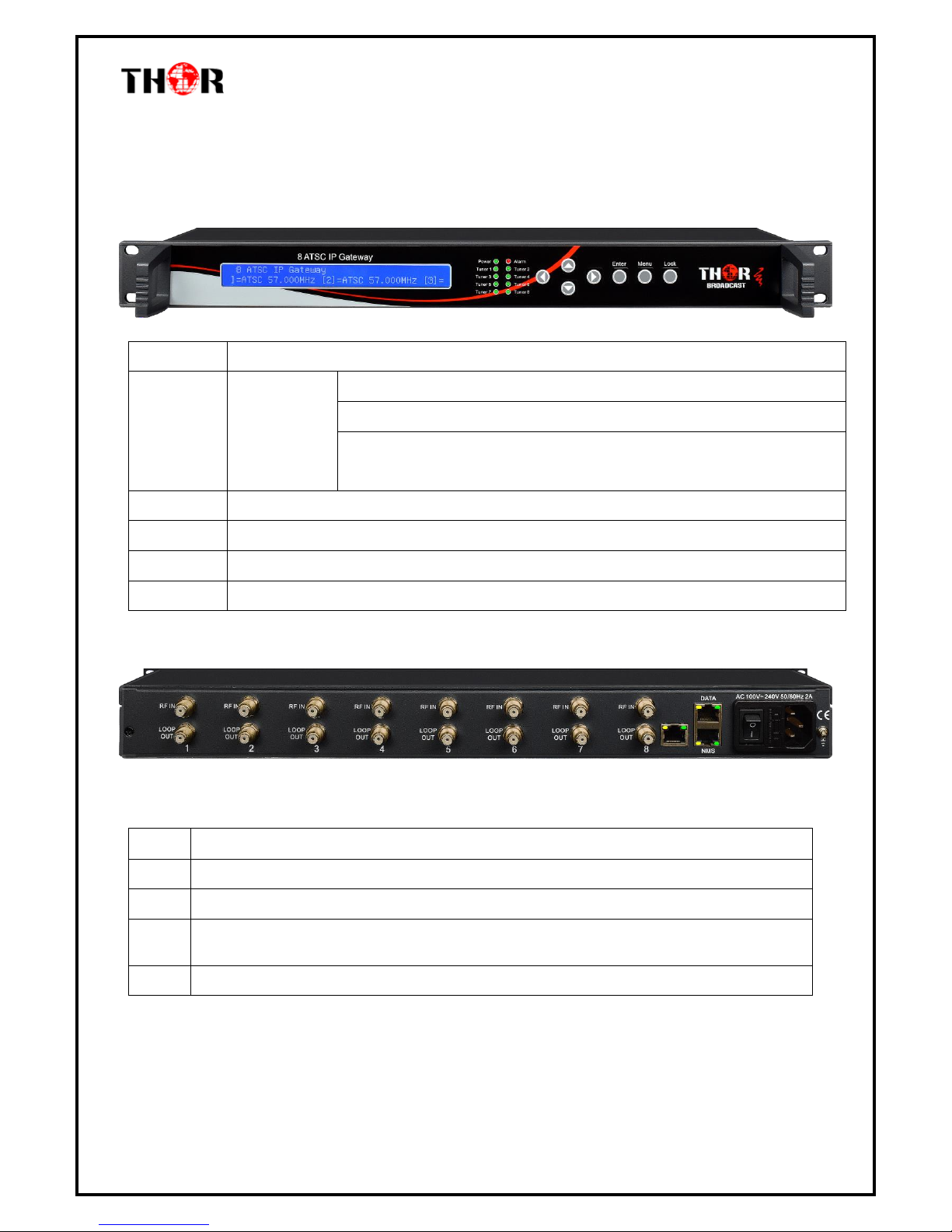
Front Panel Illustration:
1 2 3 4 5 6
1
LCD Display
2
Tuner in
Power Indicator
Alarm Indicator
Tuner 1(2/3…/8): when the input signal of tuner 1(2/3…/8) is
locked, the light becomes green. Otherwise it is red.
3
Up (▲)/Down (▼)/ Left (◄)/Right (►)button
4
Enter
5
Menu
6
Lock
Rear Panel Illustration
7 8 9 10 11
7
8 channels RF IN Interface (top row)
8
Loop Out Interface (bottom row)
9
CAS port: Network management interface
10
Ethernet port: Network management interface; Data port: IP out port
11
Integrated power switch and socket

H-8ATSC-IP
Tel: (800) 521-8467 Email: sales@thorfiber.com http://www.thorbroadcast.com
Chapter 2 - Installation Guide
This section is here to explain the cautions you should adhere to so you don’t hurt yourself or
anyone else. That would not be good for anyone; so read through before operating your new
Thor Broadcast equipment.
2.1 General Precautions
Must be operated and maintained in an area free of dust and debris.
The cover should be securely fastened, do not open the cover of the chassis when thepower is on.
This will also void Thor’s manufacturer’s warranty.
After installation, securely stow away all loose cables, external antenna, and others.
2.2 Power precautions
Be careful when connecting a power source to the device.
Do not operate in wet or damp areas. Make sure the extension cable is in good condition
Make sure the power switch is off before you start to install the device
2.3 Device’s Installation Flow Chart Illustrated (as following)
Connecting
Grouding
Wire and
Power
Cord
Acquisition
Check
Installing
Device
Setting
Parameter
Running
Device
Connecting
Signal
cable
 Loading...