

Thor Broadcast H-12SDI-ATSC-IPLL, H-12HDMI-ATSC-IPLL, H-12HDMI-ISDB-T-IPLL, H-12SDI-QAM-IPLL, H-12SDI-DVB-T-IPLL User Manual
...
12 Channel HDMI or SDI CATV RF Modulator
IP Encoder QAM/ATSC/DVB-T/ISDB-T
H-12HDMI-QAM-IPLL
H-12HDMI-QAM-IPLL
H-12HDMI-ATSC-IPLL
H-12HDMI-DVB-T-IPLL
H-12HDMI-ISDB-T-IPLL
H-12SDI-QAM-IPLL
H-12SDI-QAM-IPLL
H-12SDI-ATSC-IPLL
H-12SDI-DVB-T-IPLL
H-12SDI-ISDB-T-IPLL

H-12HDMI/SDI - QAM/ATSC/DVB-T/ISDB-T
About This Manual
This user manual has been written to help people who have to use, to integrate and to
install the product. Some chapters require some prerequisite knowledge in electronics
and especially in broadcast technologies and standards.
Disclaimer
No part of this document may be reproduced in any form without the written permission
of the copyright owner.
The contents of this document are subject to revision without notice due to continued
progress in methodology, design and manufacturing. We shall have no liability for any
error or damage of any kind resulting from the use of this document.
Copy Warning
Intended Audience
This document includes some confidential information. Its usage is limited to the
owners of the product that it is relevant to. It cannot be copied, modified, or translated
in another language without prior written authorization from us.
Tel: (800) 521-8467 Email: sales@thorfiber.com https://thorbroadcast.com

H-12HDMI/SDI - QAM/ATSC/DVB-T/ISDB-T
Directory
CHAPTER 1 INTRODUCTION ................................................................................................................... 1
PRODUCT OVERVIEW ....................................................................................................................................................................... 1
KEY FEATURES ............................................................................................................................................................................................... 1
SPECIFICATIONS ................................................................................................................................................................................. 2
FLOW CHART ...................................................................................................................................................................................... 3
CHAPTER 2 INSTALLATION GUIDE ........................................................................................................... 5
GENERAL PRECAUTIONS ....................................................................................................................................................... 5
POWER PRECAUTIONS ............................................................................................................................................................ 5
DEVICE’S INSTALLATION FLOW CHART ILLUSTRATED AS FOLLOWING .................................................................. 5
ENVIRONMENT REQUIREMENT ........................................................................................................................................... 6
GROUNDING REQUIREMENT ................................................................................................................................................ 6
CHAPTER 3 WEB NMS OPERATION ......................................................................................................... 7
LOGIN ......................................................................................................................................................................................... 7
OPERATION ....................................................................................................................................................................................................... 8
CHAPTER 4 TROUBLESHOOTING........................................................................................................... 27
CHAPTER 5 PACKING LIST ..................................................................................................................... 28
Tel: (800) 521-8467 Email: sales@thorfiber.com https://thorbroadcast.com

H-12HDMI/SDI - QAM/ATSC/DVB-T/ISDB-T
Chapter 1 Introduction
Product Overview
The Thor Broadcast H-12HDMI-QAM-IPLL Encoder-RF Modulator is a professional
high capacity solution for any headend that requires integration of encoding,
multiplexing, scrambling and modulating. It supports 12 HDMI and 12 CC inputs, one
DVB-C tuner input and 512 IP input through Data1 (GE) port. It also supports DVB-C
RF out with 16 non-adjacent carries and supports 16 MPTS which mirror the 16
carriers through the Data2 (GE) output port. To meet customers’ various requirements,
it is also equipped with 1 ASI output as mirror of one of RF output carriers. Managed
through any modern web browser, each encoder can be independently adjusted for
bitrate, codecs, and video image qualities. Encoding support for the MPEG-2, or
H.264, codec along with Dolby AC/3 audio ensure that the programs generated by this
encoder can be used around the world on a global scale.
Key Features
12 HDMI inputs with MPEG2 & MPEG4 AVC/H.264 Encoding
12 CC (Closed Caption) inputs
1DVB-C (ATSC optional) tuner input for re-mux
512 IP(DATA1 port only) input over UDP and RTP protocols
MPEG1 Layer II, MPEG2-AAC, MPEG4-AAC, Dolby Digital AC3 (2.0)
encoding (Optional), AC3 (2.0/5.1) passthrough
16 groups multiplexing/Scrambling/DVB-C modulating
1 ASI out as mirror of one of RF output carriers
16 MPTS IP (DATA2 port only) output over UDP, RTP/RTSP
PID remapping/ accurate PCR adjusting/PSI/SI editing and inserting
Control via web management, and easy updates via web
Tel: (800) 521-8467 Email: sales@thorfiber.com https://thorbroadcast.com

H-12HDMI/SDI - QAM/ATSC/DVB-T/ISDB-T
Input
12 HDMI inputs
12 CC(closed caption) input, BNC interface
1 DVB-C(ATSC optional) Tuner for re-mux, F type interface
512 IP input over UDP and RTP, DATA1, RJ45
Video
Resolution
Input
1920*1080_60p, 1920*1080_50p,1920*1080_60i,
1920*1080_50i, 1280*720_60p, 1280*720_50P,
720*480_60i, 720*576_50i
Output
1920*1080_60p, 1920*1080_50p,1920*1080_60i,
1920*1080_50i, 1440*1080_60i, 1440*1080_50i,
1280*720_60p, 1280*720_50P, 720*576_50p,
720*576_50i, 720*576_30p, 720*576_25p,
720*480_60p, 720*480_60i,720*480_30p,
720*480_25p,320*240_60p,320*240_50p,
320*240_30p, 320*240_25p,320*180_60p, 320*180_50p,
320*180_30p, 320*180_25p,
960*540_50i, 704*576_50i,704*480_60i, 640*576_50i
640*480_60i, 544*576_50i,544*480_60i,
Encoding
MPEG2 & MPEG4 AVC/H.264
Bit-rate
0.8~19Mbps for H.264 encoding
1~19Mbps for MPEG-2 encoding
Rate Control
CBR/VBR
GOP Structure
GOP B Frame: 0-3, GOP P Frame: 0-6
Advanced
Pretreatment
De-interlacing, noise reduction
Audio
Encoding
MPEG1 Layer II, MPEG2-AAC, MPEG4-AAC,
Dolby Digital AC3 (2.0) encoding (Optional),
AC3 (2.0/5.1) passthrough
Sampling rate
48KHz
Bit-rate
64Kbps-320kbps each channel
Multiplexing
Maximum PID
Remapping
180 input per channel
Function
PID remapping ( automatically or manually)
Accurate PCR adjusting
Generate PSI/ SI table automatically
Scrambling
Maximum
simulcrypt CA
4
Standard
ETR289, ETSI 101197, ETSI 103197
Connection
Local/remote connection
Modulation
QAM Channel: 16 non-adjacent carriers output (maximum bandwidth
192MHz)
Specifications
Tel: (800) 521-8467 Email: sales@thorfiber.com https://thorbroadcast.com
H-12HDMI/SDI - QAM/ATSC/DVB-T/ISDB-T
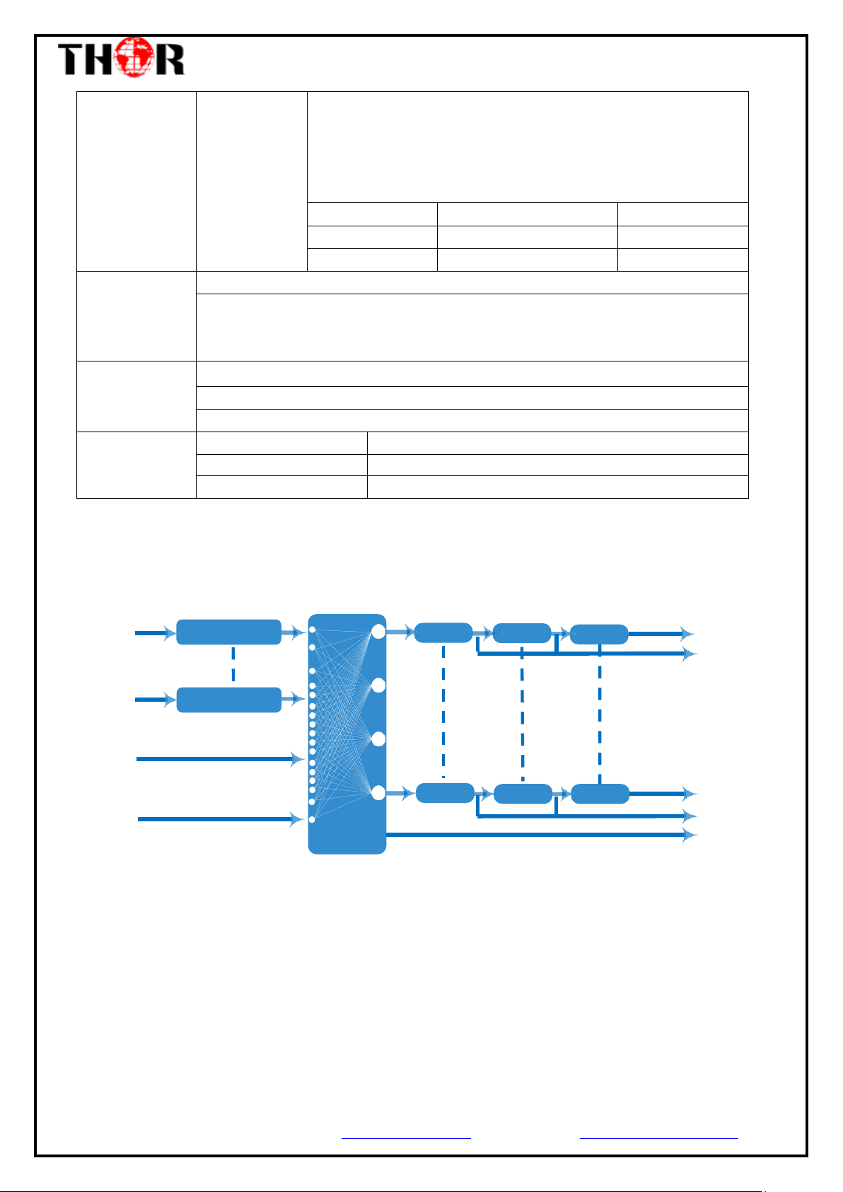
HDMI #1
Encoding
MUX 1#
SCR1#
Carrier 1
DVB-C 1#
IP 1
HDMI #12
Encoding
IP1-256
MUX 16#
SCR16#
DVB-C 16#
Carrier 16
DVB-C Tuner
IP 16
1 ASI (asmirror of one of RF output carriers)
DVB-C
Standard: EN300 429/ITU-T J.83A/B
MER: ≥40db
RF frequency: 50~960MHz, 1KHz step
RF output level: -20~+10dbm, 0.1db step
Symbol Rate: 5.0Msps~7.0Msps, 1ksps stepping
J.83A
J.83B
Constellation
16/32/64/128/256QAM
64/256 QAM
Bandwidth
8M
6M
Stream output
RF output (F type interface)
1 ASI output as mirror of one of RF output carriers
16 MPTS output over UDP and RTP/RTSP as mirror of 16 DVB-C carriers,
1*1000M Base-T Ethernet interface
System function
Network management (WEB)
English
Ethernet software upgrade
Miscellaneous
Dimension (W×L×H)
482mm×440mm×44mm
Environment
0~45℃(work);-20~80℃(Storage)
Power requirements
AC 110V± 10%, 50/60Hz, AC 220 ± 10%, 50/60Hz
Flow Chart
Tel: (800) 521-8467 Email: sales@thorfiber.com https://thorbroadcast.com
H-12HDMI/SDI - QAM/ATSC/DVB-T/ISDB-T
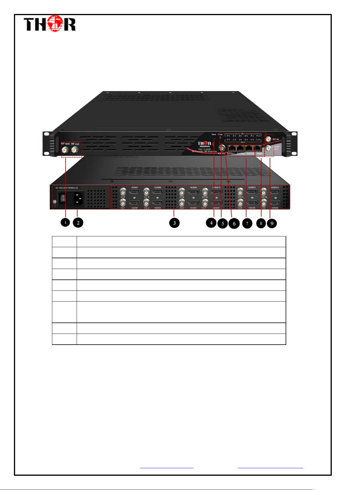
1
RF test and RF out port
2
Power supply and Grounding Pole
3
12 HDMI and 12 CC input port
4
Reset Key
5
LED Indicators
6
ASI output port
7
DATA Port (DATA1 and DATA2 for IP stream input/output, DATA 3 for
upgrading modules)
8
NMS port for web-based management
9
RF in and Loop out port
Appearance and Description
Front and Rear Panel Illustration
Tel: (800) 521-8467 Email: sales@thorfiber.com https://thorbroadcast.com

H-12HDMI/SDI - QAM/ATSC/DVB-T/ISDB-T
Setting
Parameter
Connecting
Signal
cable
Connectin
g Grouding
Wire and
Power
Cord
Installing
Device
Device
Check
Running
Device
Chapter 2 Installation Guide
Please use caution when operating this device in order to abstain from any possible injuries during
installation. For this reason, please read all details listed below and make sure you use caution before
proceeding to operate and use this device.
General Precautions
Must be operated and maintained free of dust or debris.
The cover should be securely fastened, do not open the cover of the products when the power
is on.
After installation, securely stow away all loose cables, external antenna, and others.
Power precautions
When you connect the power source, make sure it is grounded correctly so it doesn’t cause an
overload.
Avoid operating on a wet floor in the open. Make sure the extension cable is in good
condition.
Make sure the power switch is off before you start to install the device.
Device’s Installation Flow Chart Illustrated as following
Tel: (800) 521-8467 Email: sales@thorfiber.com https://thorbroadcast.com

H-12HDMI/SDI - QAM/ATSC/DVB-T/ISDB-T
Item
Requirement
Machine Hall
Space
When user installs machine frame array in one machine hall,
the distance between 2 rows of machine frames should be
1.2~1.5m and the distance against wall should be no less than
0.8m.
Machine Hall Floor
Electric Isolation, Dust Free
Volume resistivity of ground anti-static material:
1X10⁷~1X10¹⁰,Grounding current limiting resistance: 1M
(Floor bearing should be greater than 450Kg/㎡)
Environment
Temperature
5~40℃(sustainable ),0~45℃(short time),
installing air-conditioning is recommended
Relative Humidity
20%~80% sustainable 10%~90% short time
Pressure
86~105KPa
Door & Window
Installing rubber strip for sealing door-gaps and dual level
glasses for window
Wall
It can be covered with wallpaper, or paint.
Fire Protection
Fire alarm system and extinguisher
Power
Requiring device power, air-conditioning power and lighting
power are independent to each other. Device power requires
AC 110V±10%, 50/60Hz or AC 220V±10%, 50/60Hz. Please
carefully check before running.
Environment Requirement
Grounding Requirement
It is important to keep this device grounded to ensure all of the modules
function correctly. Correctly grounding the device will also help prevent any
electrical interference, lightening. Etc. Also it helps reject minor interference that
may disrupt the devices ability to function smoothly. General rule of them, make
sure the device is grounded when installing anywhere.
Tel: (800) 521-8467 Email: sales@thorfiber.com https://thorbroadcast.com
Always use copper wire. When applied correctly the ground must be wrapped

H-12HDMI/SDI - QAM/ATSC/DVB-T/ISDB-T
device setting.
well to ensure maximum conduction so it can reduce any high frequencies. The
copper ground wire should also be as short and thick as possible
Installer must make sure that the two ends of the ground are well conducted
and have appropriate anti-rust properties.
It is prohibited to use any other device as part of the grounding electric
circuit.
The area of the conduction between the ground wire and device’s frame
should be no less than 25 ㎡.
Chapter 3 WEB NMS Operation
You must connect the Encoder Modulator to a PC in order to setup the configuration, to
control and set configure the settings you must plug the device into web NMS Port. Users
should ensure that the computer’s IP address is different from this device’s IP address;
otherwise, it would cause IP conflict.
Login
The default IP address of this device is 192.168.0.136.
Connect the PC (Personal Computer) and the device with net cable, and use ping
command to confirm they are on the same network segment.
I.G. the PC IP address is 192.168.99.252, we then change the device IP to 192.168.99.xxx
(xxx can be 1 to 254 except 252 to avoid IP conflict).
Use web browser to connect the device with PC by inputting the Encoder Modulator’s IP
Tel: (800) 521-8467 Email: sales@thorfiber.com https://thorbroadcast.com
address in the browser’s address bar and press Enter.
It will display the Login interface as Figure-1. Input the Username and Password (Both
the default Username and Password are “admin”.) and then click “LOGIN” to start the
 Loading...