

Page 1
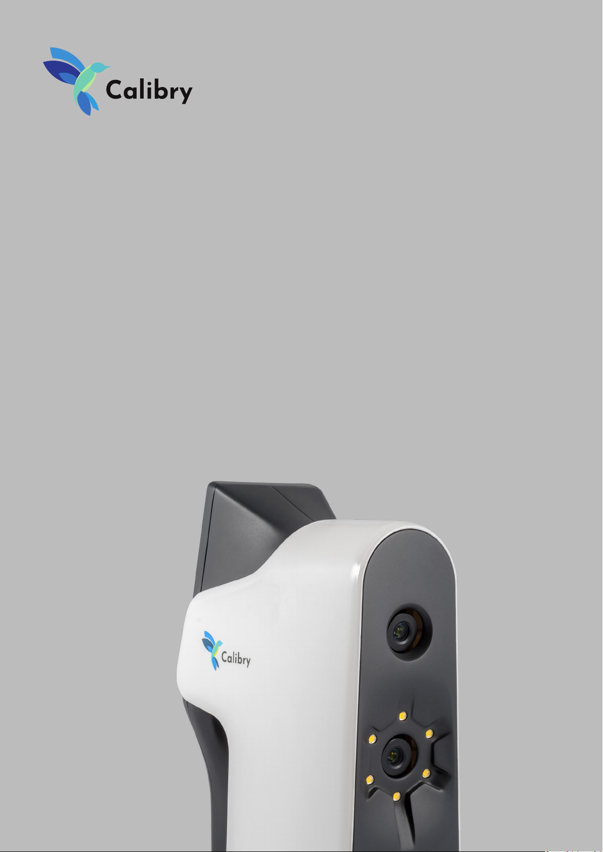
3D scanner
User manual
Page 2

Page 3
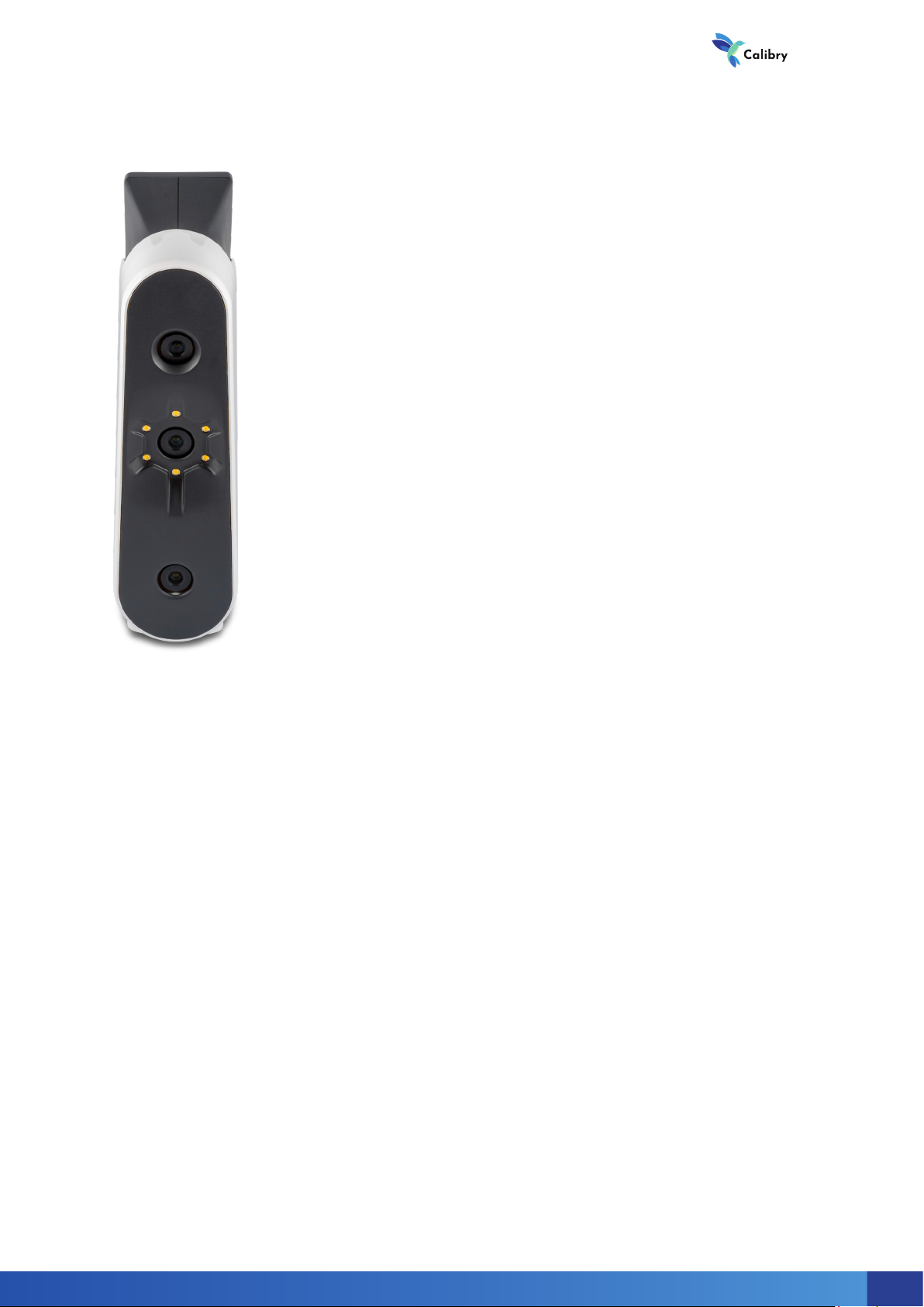
3D scanner
Congratulations on your purchase of the latest
professional 3D scanner Calibry!
The device uses the latest developments in structured
light scanning and even enables the capture of complex
surfaces.
This guide provides information on how to install and
use Calibry software, how to operate the scanner, and
recommendations for the scanning process itself.
When using the device, keep in mind that the 3Dscanner
is a high-precision optical device that requires careful
attention. Careful use and compliance with the rules of
use will ensure a long life for the scanner.
1
Page 4
User manual
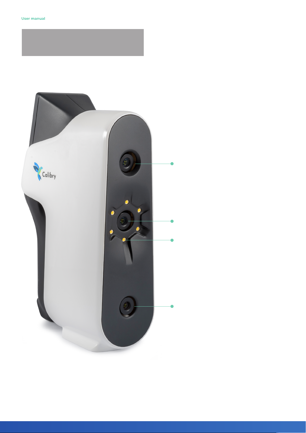
Scanner hardware
device
Front panel
Geometric camera
Tex ture camera
Texture ash
Projector
2
Page 5
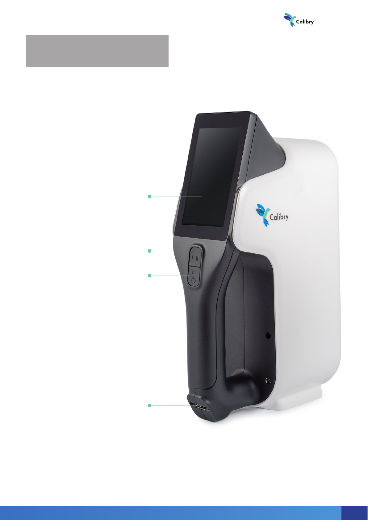
Scanner hardware
device
Rear panel
Touch screen
3D scanner
Button «START»
Button «STOP»
Scanner data
cable connector
3
Page 6
User manual
Pre-starting
procedure
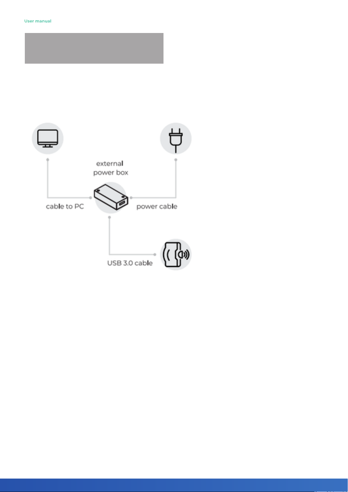
Connect the scanner to a computer with the Calibry Nest
software installed.
• Strictly follow the connection sequence. Make all connections when
the power supply unit is disconnected. Connect the power supply unit
when all other connections have been made. Otherwise, the equipment
may be damaged, and this case will not be covered under the warranty.
When the scanner is powered on, it turns on automatically.
• When you rst connect the scanner to the computer, we recommend
that you connect the computer to the Internet. In this case, the software
will automatically download the scanner calibration le, and the scanner
will be ready for use. Otherwise, you can manually download the calibra-
tion le. The calibration le can be requested from the supplier of the
scanner.
4
Page 7
Scanner
operation
Main screen elements
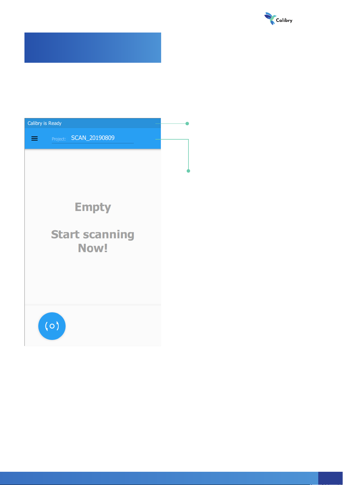
After the scanner is loaded, the main screen is displayed
3D scanner
Status bar
The status bar shows the
status of the scanner
Control panel
The control panel is used
to display the sidebar.
Here you can also specify
the name of the current
project (the object being
scanned) by clicking on
the title in the centre.
All scanned parts of the
object will be placed in
the folder with this name.
If the project name is not
specied or is empty, a
standard name indicating
the full scan date will
be applied, for example,
«SCAN_ 20200101».
5
Page 8
User manual
Scanner
operation
List of scans
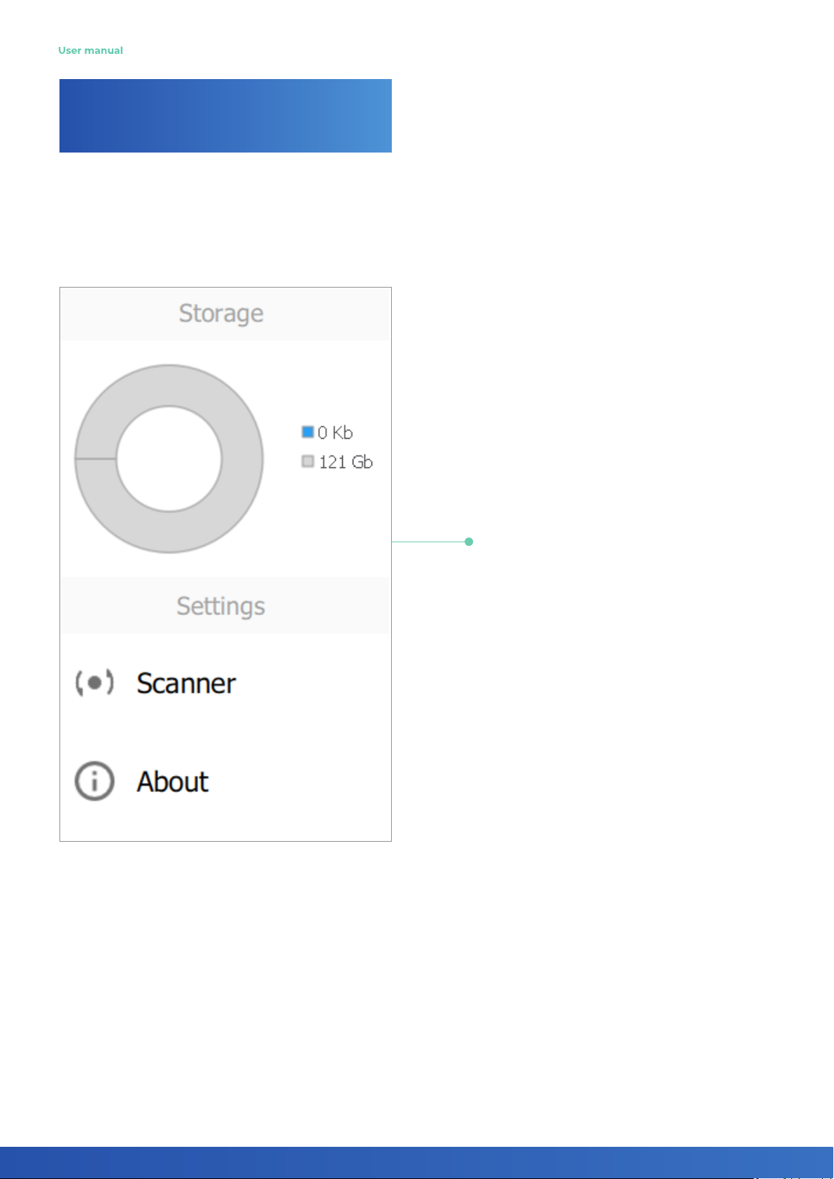
The sidebar
presents information on
the available and occupied
space on the hard disk of
the computer, to which the
scanner is connected, as
well as buttons for scanner
settings and the scanner
data.
6
Page 9
Scanner
operation
List of scans
3D scanner
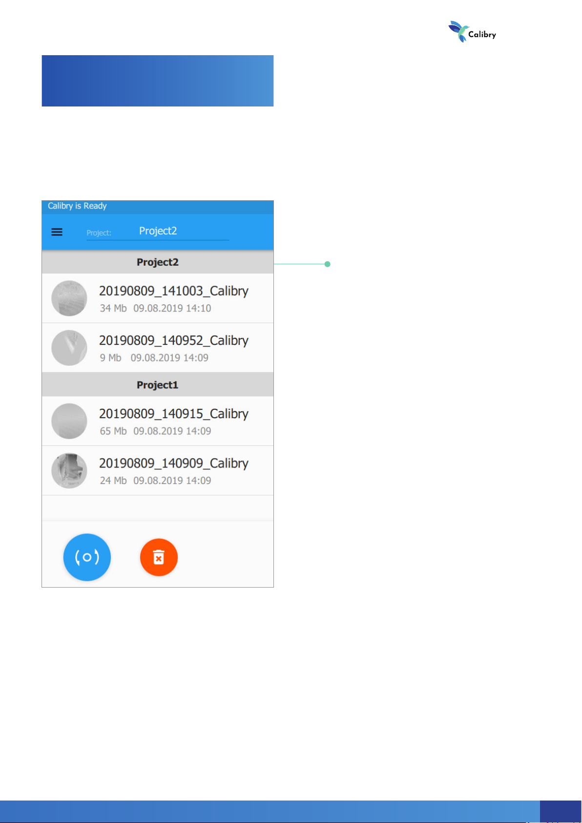
The list of scans
During the scanning process, the list of all scans
carried out will be placed
on the main screen. The
scans are sorted by creation date: the newer, the
higher. Scans can also be
grouped in their respective
project sections. At any
time, you can switch to
another project by clicking on the section bar, or
create a new project by
typing its name in the title.
All scans carried out are
saved to the hard disk of
the computer to which the
scanner is connected.
7
Page 10
User manual
Scanner
operation
List of scans
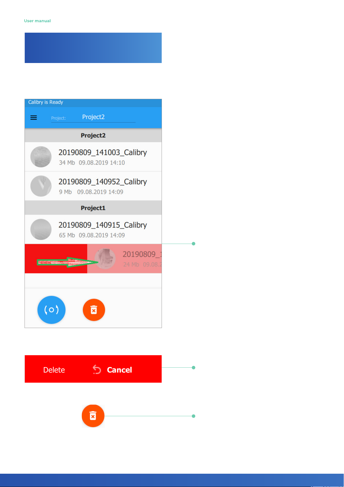
Any scan in the project
can be deleted by simply
swiping the item in the list
sideways.
You can cancel the
deletion within 5 seconds
by clicking the «Cancel»
button.
You can delete all scans
by clicking the «Delete All
Scans» button
8
Page 11
Scanner
operation
Preview Mode
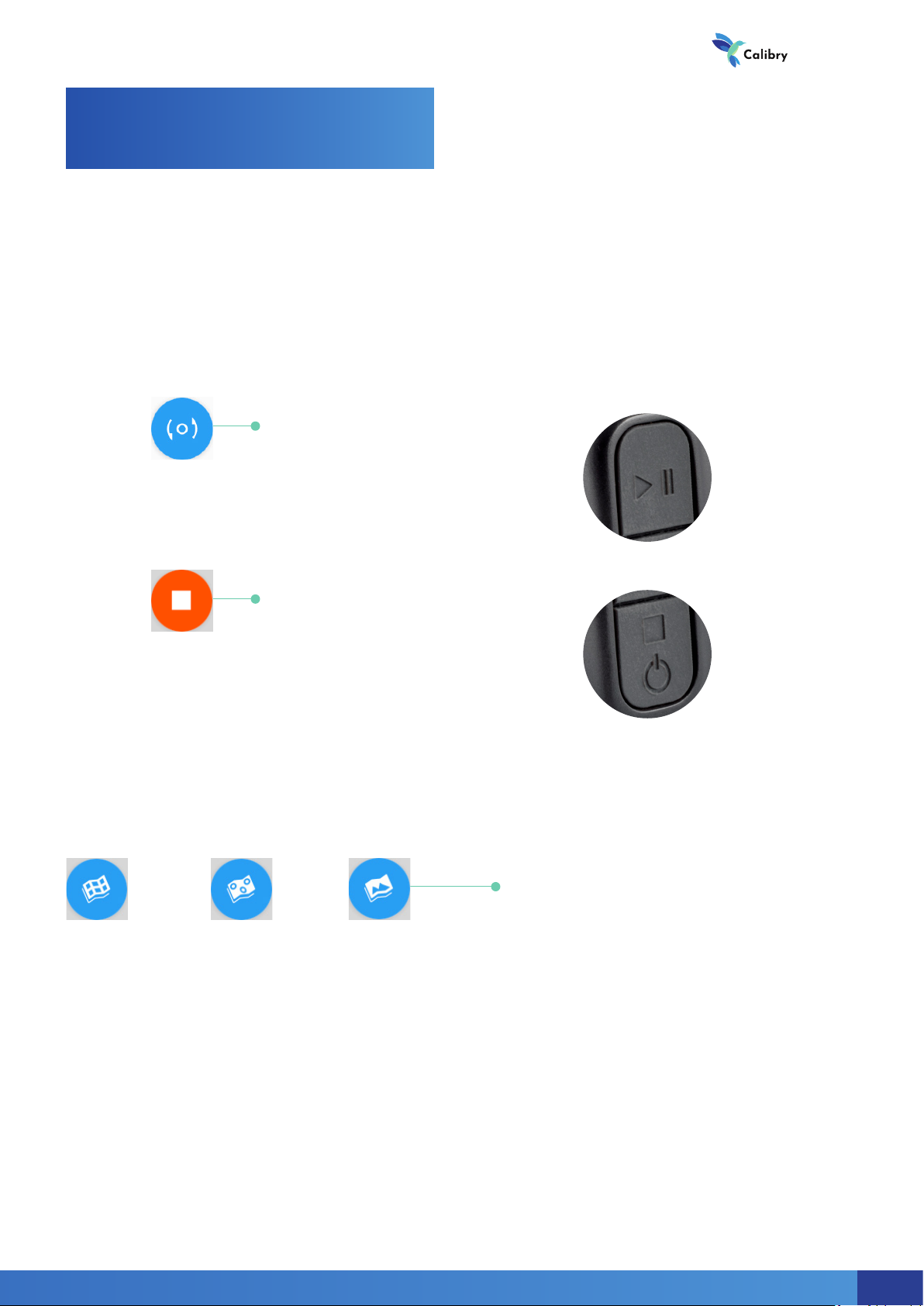
The preview mode allows you to select the correct scan angle, to determine
the optimal distance, to assess the nature of the surface, to set up the scan parameters, and to determine the adequacy of the number of markers applied.
To enter the mode, press the
button, on the main screen of the
scanner. For convenience, you can
also use the mechanical button
located under the screen.
3D scanner
To exit the main screen, press the
button, at the bottom of the screen.
For convenience, you can also use
the mechanical button located
under the screen.
In the preview mode, additional buttons appear on the screen allowing
you to adjust the scan settings.
Scan mode selection
button
With tracking
by geometry
With tracking
by markers
With tracking
by texture
Selection of scanning modes with tracking by geometry, markers and texture, respectively. Depending on the mode selected data visualization on
the scanner screen in the preview and scan modes has its own specic features.
9
Page 12
User manual
Scanner
operation
Preview Mode
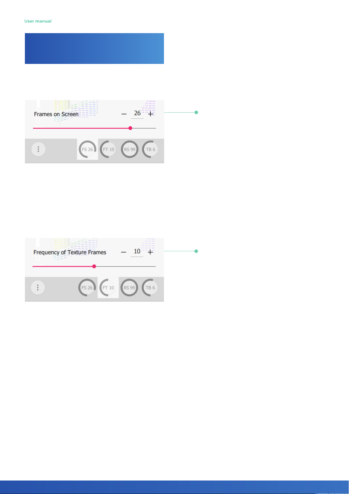
Screen frames rate
This parameter determines the frame update rates on the scanner screen
during preview and scan modes. Increase the setting value to improve the
picture quality displayed on the scanner screen. If increasing the value slows
down the scanning, decrease it back.
Texture frames rate
This parameter determines the rate of recording frames by the texture
camera, necessary for building a textured model. For example, if the value
of this parameter is 10, then every 10th frame taken during shooting is
used to scan texture.
Recommended value for shooting with texture 20.
Decrease the setting value to increase the number of texture frames in the
project. In some cases, this can improve texturing.
Increase the setting value to decrease the number of texture frames in the
project. In some cases, this can improve texturing as well. And in any case,
this will reduce the project volume and post-processing time.
The parameter does not affect tracking by markers and texture.
!
10
Page 13
Scanner
operation
Preview Mode
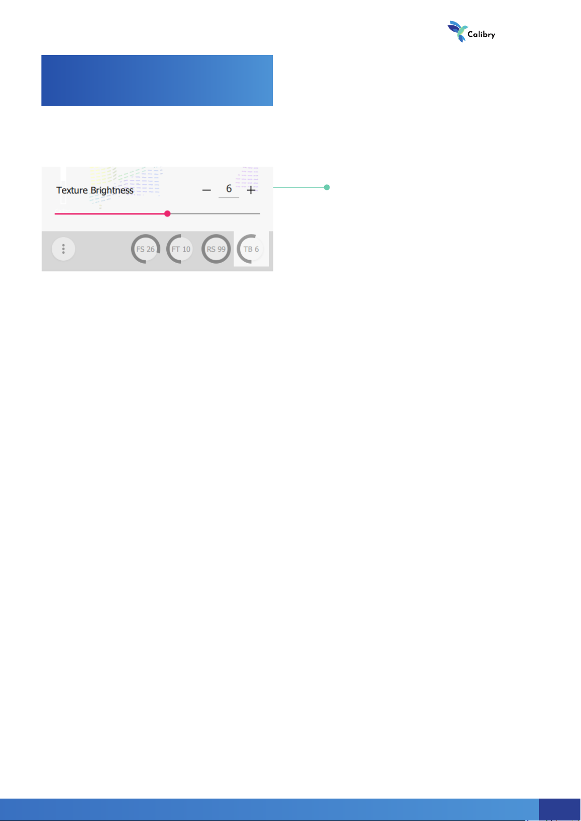
Texture brightness
This parameter determines the frame texture brightness.
If you change the value of this parameter, the image from the texture camera is displayed on the scanner screen, so you can visually assess the texture
quality in advance.
Set the parameter value so that the texture is displayed in the best quality. Before scanning, in preview mode analyze the texture image in different
parts of the scanned surface. In case of glare, the corresponding surface areas will be tinted in red.
3D scanner
11
Page 14
User manual
Scanner
operation
Preview Mode
Projector capacity
Set this parameter to one of the following values.
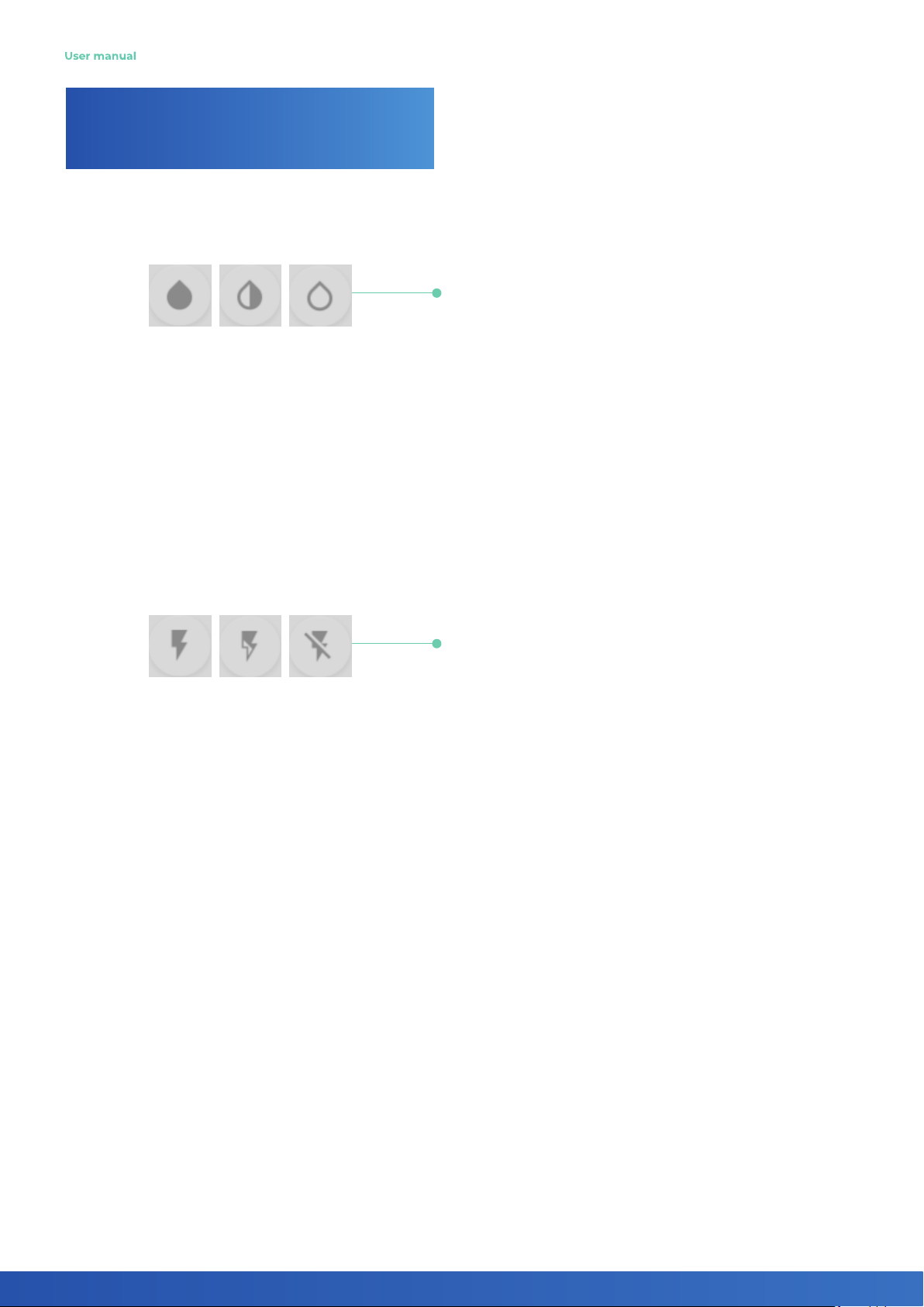
To select the maximum, average or minimum projector capacity, respectively.
As a rule, the maximum capacity mode is used to scan dark objects. The
minimum capacity mode is recommended for scanning shiny objects. The
default mode is average capacity.
Texture ash capacity
Set this parameter to one of the following values.
To select the maximum, average or minimum texture ash capacity, respectively. Setting the parameter is done visually, similar to the setting «Texture
brightness»
The setting is available in geometry tracking mode only.
!
12
Page 15
Scanner
operation
Scan mode
3D scanner
To start the scan session in the preview
mode, press the button at the bottom
of the screen.
For convenience, you can also use the
mechanical button located under the
screen.
To nish the scan session, click the
button at the bottom of the screen.
For convenience, you can also use the
mechanical button located under the
screen.
Upon nishing the scan session, the scanner shifts to the preview mode.
13
Page 16

User manual
Scanner
operation
Scanning in geometry tracking mode
Use the geometry tracking mode when capturing objects with distinct
geometry and without many at parts.
Scan rate
(frames per second)
Number of frames shot
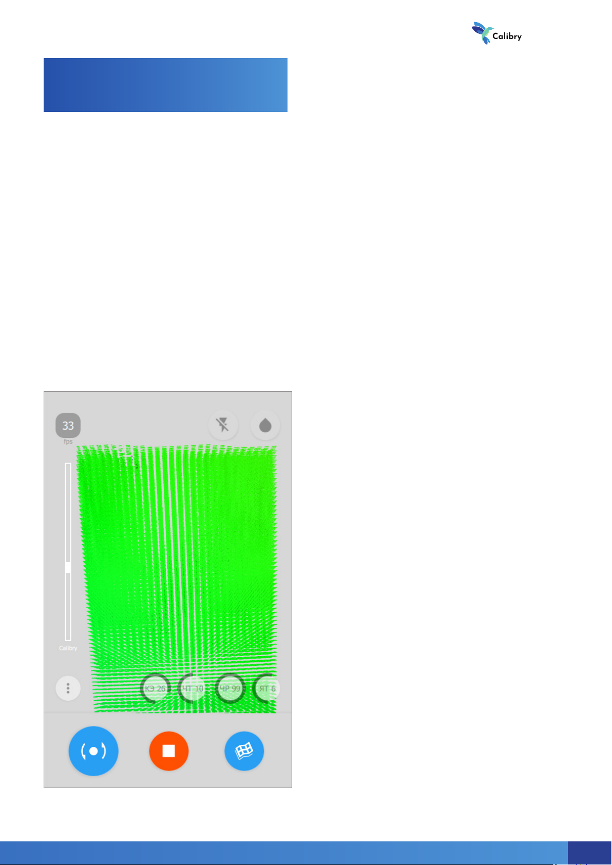
During scanning, it is important to keep the
optimal distance between the scanner and
the object being scanned. For convenience,
and depending on the distance, the scanned
surface is tinted with a certain colour. The colour
from the middle part of the spectrum (green)
indicates that the scanning distance is close to
optimal. If the scanning distance is too small, the
object is tinted with the colours from the lower
part of the spectrum (yellow – orange − red). If
the scanning distance is too large, the object
is tinted with the colours from the upper part
of the spectrum (light blue – blue − purple). It
is recommended that as much of the object as
possible is tinted with the green colour during
scanning.
14
Page 17
Scanner
operation
Scanning in marker tracking mode
Scan in marker tracking mode if the object does not have characteristic features of geometry or texture, as well as if these features make up a periodically repeating pattern.
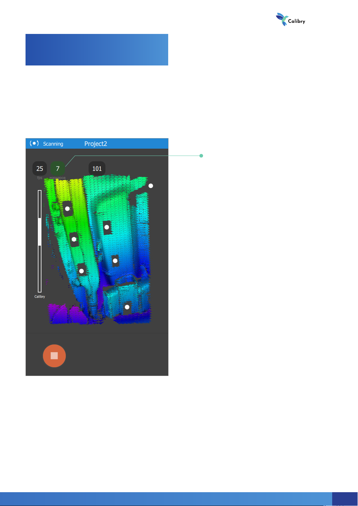
Number of markers in
the frame
3D scanner
When scanning by markers, it is important
that each frame shot contains at least 3 markers (this is a critical value), optimally at least
5 markers. The indicator changing the colour
depending on the xed number of markers in
the last frame helps to control the number of
markers:
• If it is 4 or less, the indicator is red (critically)
• If it is 5, the indicator is yellow (warning)
• If it is more than 5, the indicator is green
(good)
If there are not enough markers in the frame
(less than three), the scanning will automatically
stop, and the scanner will return to the preview
mode. Then you should nd a more comfortable position to scan and start again.
Sometimes, the object you are scanning is small enough that it ts comfortably into a single
frame. In this case, you can place the markers around the object (on the table or the oor),
instead of adding them directly onto the object.
!
15
Page 18
User manual
Scanner
operation
Scanning in texture tracking mode
Scan in texture tracking mode if the object has characteristic texture features,
while scanning in geometry or marker tracking mode is not possible.
Far border
of the scanner working
area
Near border
of the scanner working
area
Near border
of the scanned area
Far border
of the scanned area
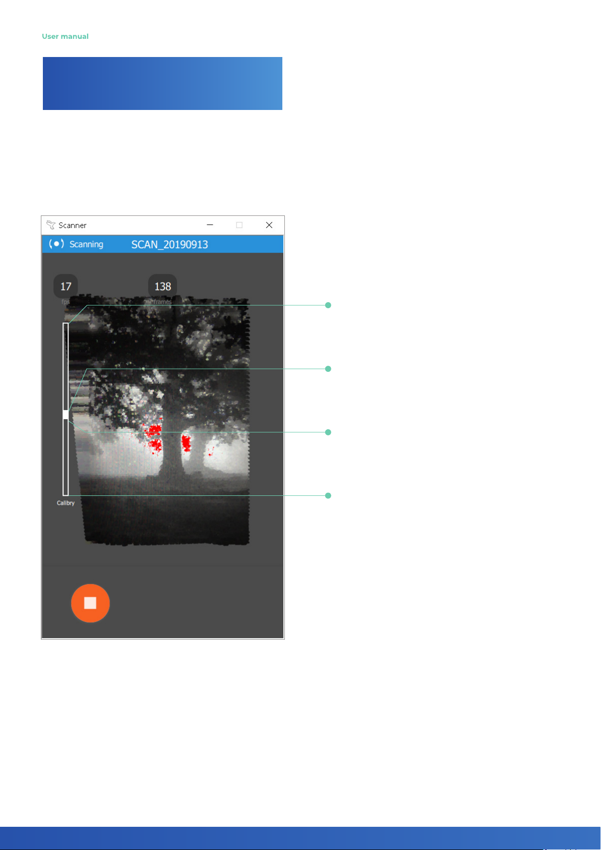
When scanning in texture tracking mode, a textured image is displayed on
the scanner screen. To maintain the correct scanning distance, use the scale
on the left. If the correct distance to the object is not maintained during scanning, the image on the screen will «crumble». Red areas on the scanned surface
indicate glare. If they appear, decrease the value of the Texture Brightness parameter and / or change the scanning angle.
16
Page 19
Scanner
operation
Calibration of the scanner
The Calibry scanner is an accurate measuring tool that is factory calibrated.
In order to ensure high scanning accuracy, Calibry has the option of custom
calibration.
A simple test is sufcient to detect if the scanner needs to be calibrated. In
geometry tracking mode, try to «look» at a at object, such as a oor or a wall,
by means of the scanner. The atness should be seen without «holes» and
distortions.
However, even with the correct restoration of the atness, it is recommended
to calibrate the scanner from time to time. The frequency of calibration de-
pends on the intensity of use of the scanner. For daily use, it is recommended
to calibrate the scanner twice a week.
3D scanner
17
Page 20
User manual
Scanner
operation
Calibration of the scanner
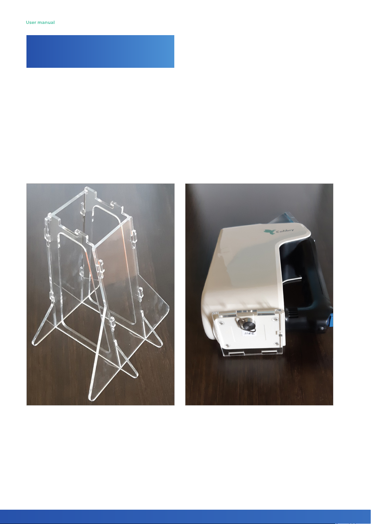
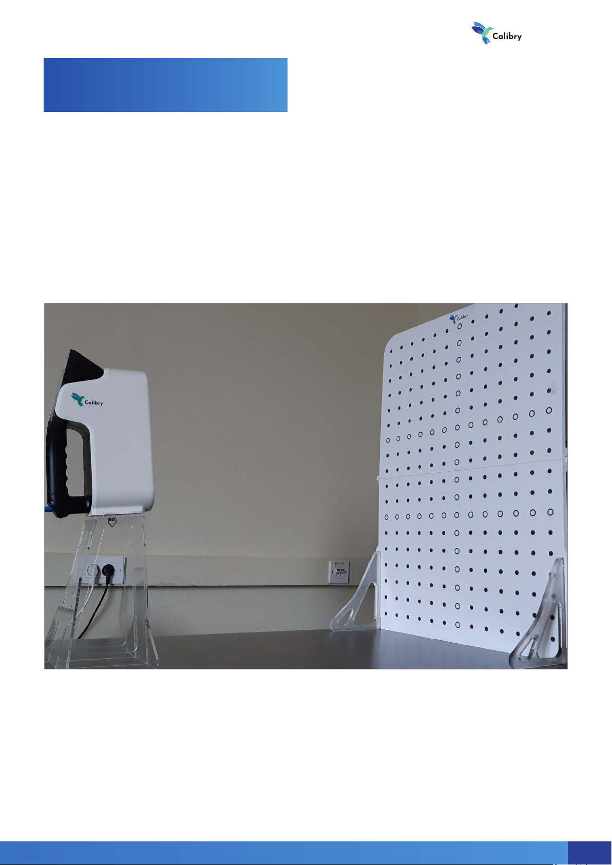
To prepare for calibration, assemble the calibration stand.
For easy assembly, it is recommended to screw the top panel of the stand
to the scanner in advance.
Place the scanner about 50 cm away from the calibration stand.
18
Page 21
Scanner
operation
Calibration of the scanner
Everything is ready for calibration. To start the calibration procedure, turn
on the scanner and go to the side panel.
• Select «Scanner» and «Calibration»
• Click «START»
3D scanner
The device will start scanning, and the message will appear on the screen
asking you to move the scanner to the rst position. Follow the on-screen
prompts to place the scanner in the rst position.
19
Page 22
User manual
Scanner
operation
Calibration of the scanner
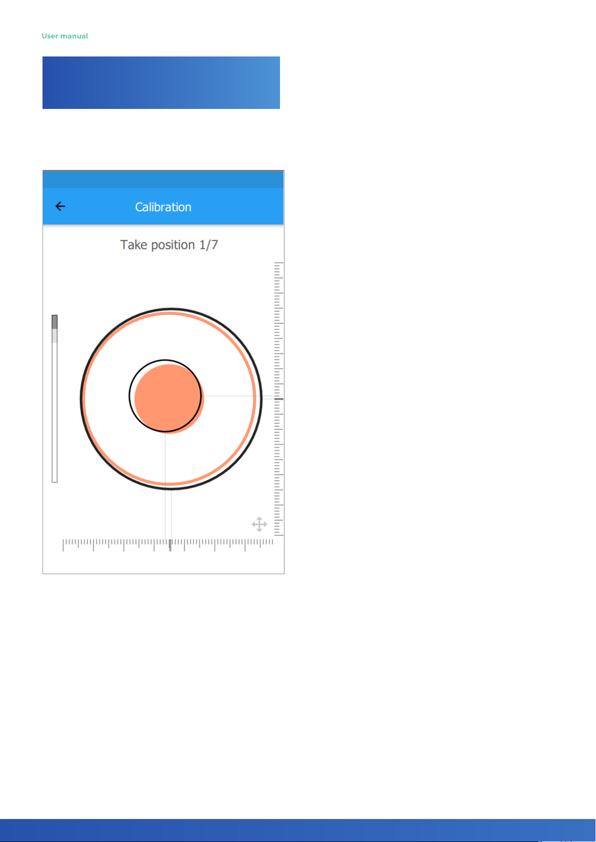
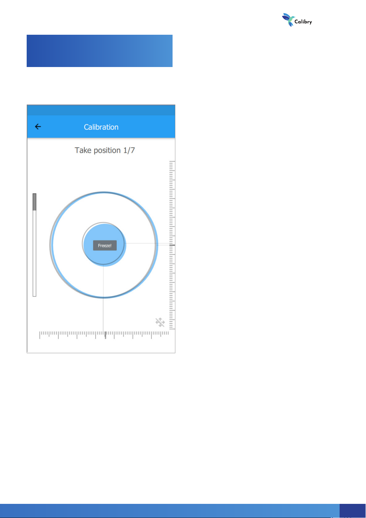
The scanner needs to be aligned in three
directions:
1. Find a suitable distance to the calibration
board by moving the scanner stand towards
it or away from it. The indicator on the left
side of the screen shows when the device is
at the required distance.
2. Rotate the scanner a few degrees left and
right until the smaller of the two red circles
aligns with the black circle of the same size.
3. Move the scanner stand slightly to the left
and right until the large red circle aligns with
the black circle of the same size.
20
As soon as the desired position is found, the
scanner will display the message «Freeze»,
and the red circles will become blue. Do not
move the scanner during this time. It will take
2−3 seconds. Once the position is recorded,
the screen will display the message about
transition in the second position.
Page 23
Scanner
operation
Calibration of the scanner
3D scanner
Slowly move the scanner away from the
calibration board. The indicator on the left
side of the screen lets you know how much
the scanner should be moved. As soon as the
software nishes the calibration in the second
position, it will move to the third one, the fourth
one, etc. There are seven positions in total.
Once the scanner is calibrated in all seven
positions, you will be prompted to restart
the scanner software and the device will be
ready for use.
21
Page 24
Page 25

3D scanner
Software manual
Page 26

Software manual
Introduction
Calibry software is designed for scanning process control, saving data ac-
quired during scanning and subsequently processing the acquired data. The
software (SW) includes several modules.
Calibry Tray Manager. This module is designed to provide the scanning pro-
cess and to acquire raw data.
Calibry Nest. This module is designed for raw data postprocessing and sav-
ing of the obtained 3D model in a conventional format.
Additionally, SW components include a Visual C++ Redistributable 2015 x64
package and FTD3XX Driver as part of the installation package.
24
24
Page 27
System Requirements
Operating system – Windows 8.1, 10
Processor – Intel Core i5 or faster
Graphics card – NVIDIA GeForce 400 series or higher (with memory size of
2048Mb)
RAM size – 16 GB minimum
USB 3.0
Installation and First Startup
To install the software onto your laptop or computer, launch the .msi le included with your scanner, and follow the instructions.
3D scanner
If there is more than one graphics card in your computer (e.g., both Intel and NVIDIA) make sure that Calibry software always uses the more
high-performance graphics card by default. We do not recommend that
you use screens with 4K resolution.
!
To start, double-click the Calibry Nest icon.
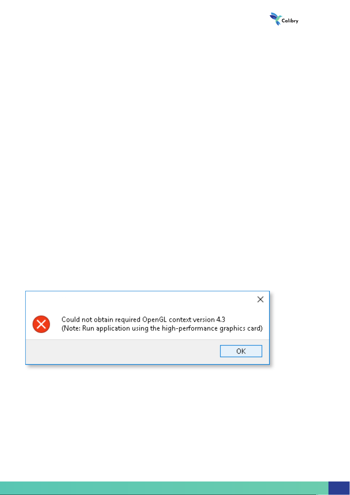
If the following error message is displayed during startup:
Then, most likely, a minimum recommended graphics card supporting
OpenGL 4.3 is not installed on your computer. Alternatively, if you have two
graphics cards, the software may be using the weaker graphics card for startup by default.
25
Page 28
Software manual
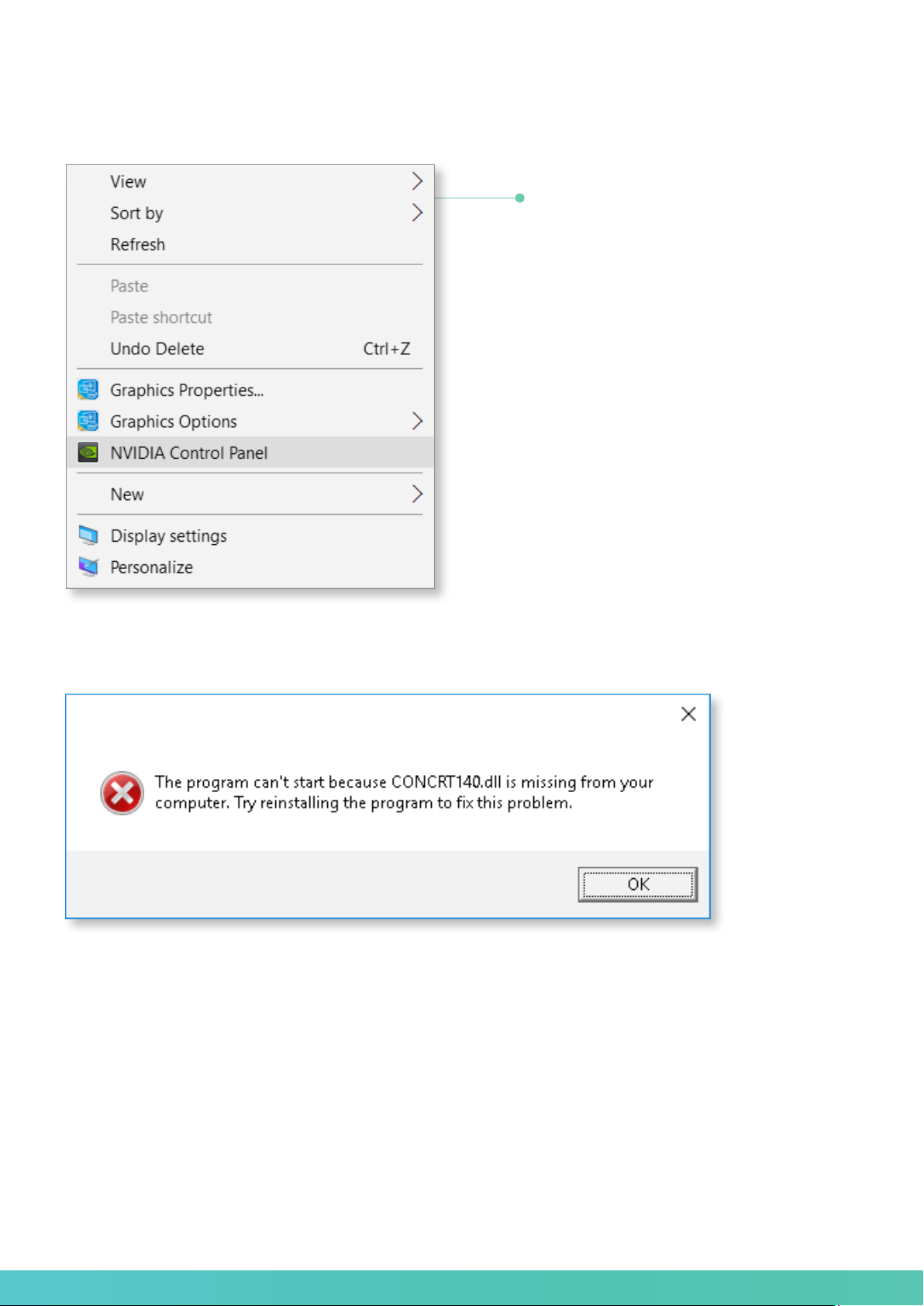
In order to switch the default graphics card, follow the instructions below:
Right-click on desktop menu
Select NVIDIA Control Panel.
Enter the Manage 3D Settings menu
and open Program Settings.
Click Add and select the nest.exe
program from the list. If there is no such
program in the list click Browse…, select
the folder with the program and click on
nest.exe
Try to restart the program. If the error
persists, you will have to upgrade your
graphics card by replacing it with a
newer one.
If during startup this error message is displayed:
Then your laptop or computer does not have the Visual C++ Redistributable
2015 x64 package with the necessary vcredist_x64.exe le. This can be easily
corrected by downloading the necessary le from the Microsoft web site and
installing it yourself:
https://www.microsoft.com/en-us/download/details.aspx?id=48145
On successful startup, the Calibry Nest window will open, and in the notication area in the right-bottom corner the Calibry Tray Manager icon will
appear.
26
26
Page 29
Preparing to Work with Calibry Scanner
Connecting a Scanner
After Calibry software has been successfully launched, the scanner can be
connected to the computer. Always follow the scanner operation instructions.
Connect power to the scanner after all other connections have been made.
Otherwise, the scanner could be damaged, and in this instance a defect is not
considered under warranty.
Calibration File
Each Calibry scanner is supplied with a calibration le containing its individual settings. If necessary, a calibration le can be requested from distributor.
To interact with the scanner its calibration le should be loaded to Calibry
Nest. If you plan to connect several scanners to one computer then calibra-
tion les should be loaded for each one of them.
When the scanner is connected for the rst time it is recommended to connect the computer running Calibry Nest to Internet. The software will then
automatically download its calibration le from the Internet, and the scanner
will be ready to use. When there is no Internet connection the calibration le
can be loaded manually.
3D scanner
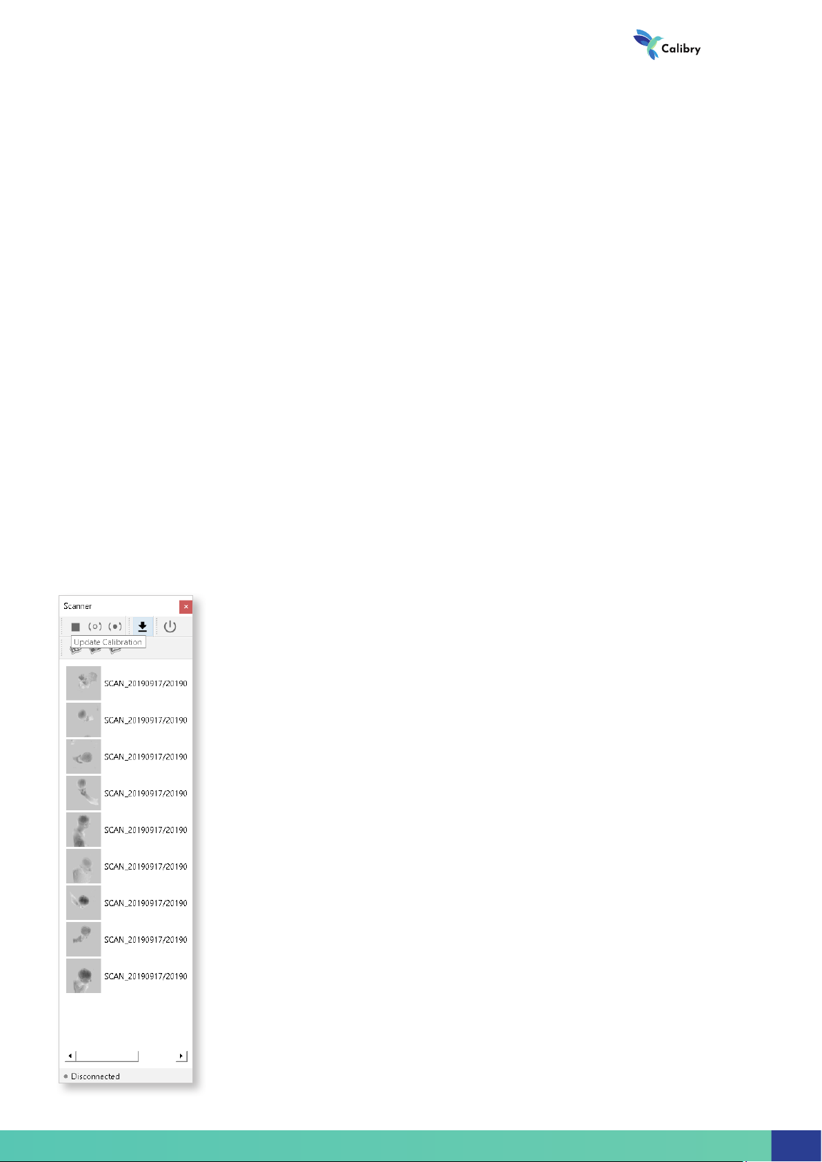
Click Update Calibration in the toolbar of the Scanner
window or select a similar option in the Help menu. In
the standard dialog box specify the calibration le.
If the scanner is connected correctly and its calibration
le is loaded to Calibry Nest then everything is ready
for scanning. This is signaled by the Ready message in
the status bar located at the bottom of the Scanner
window.
27
Page 30
Software manual
Calibry Tray Manager – Scanning
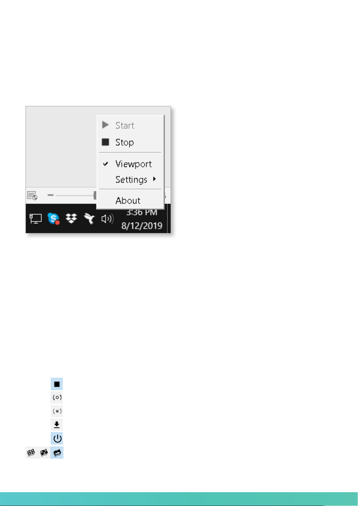
Interaction with the Calibry scanner is provided by the Calibry Tray Manager
module. This component operates in background mode. Its work is indicated
by the corresponding icon in the toolbar. By right-clicking the icon some actions can be performed.
Start/Stop – start up or stop the module.
Viewport – duplicate the scanner screen on your PC.
Settings – module settings:
• Start by Connect – automatic module startup when scanner connection is
detected;
• Start by Button – automatic module startup when the Start button is
pressed on the scanner;
• Startup with System – automatic module startup when the computer is
booted up.
About – module version.
The Scanner window is provided for the scanner to work in Calibry Nest.
Scanner control buttons are located at the top of the window:
• Exit from preview/scanning mode;
• Start Preview mode;
• Start Scanning mode;
28
28
• Load Calibration le;
• Switch scanner ON/OFF;
• Select Scanning mode
(tracking by geometry/markers/texture).
Page 31
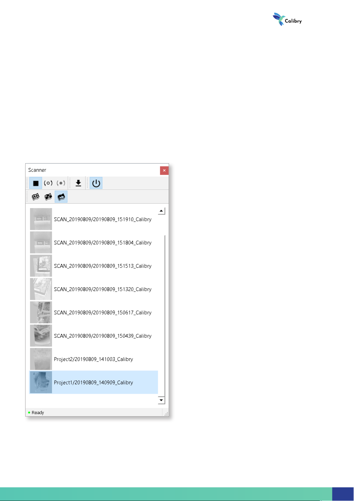
The scan list is located under the control button. To begin working with a
scan, double-click the respective line, and raw data will be opened for
postprocessing. Right-click the scan list to activate the pop-up menu:
• Open folder – click to select a folder where scans will be saved;
• Refresh – update the scan list.
A status bar is located at the bottom of the Scanner window, where the
current status of the scanner connected to computer is displayed.
3D scanner
29
Page 32
Software manual
Calibry SW – Postprocessing
Raw Data
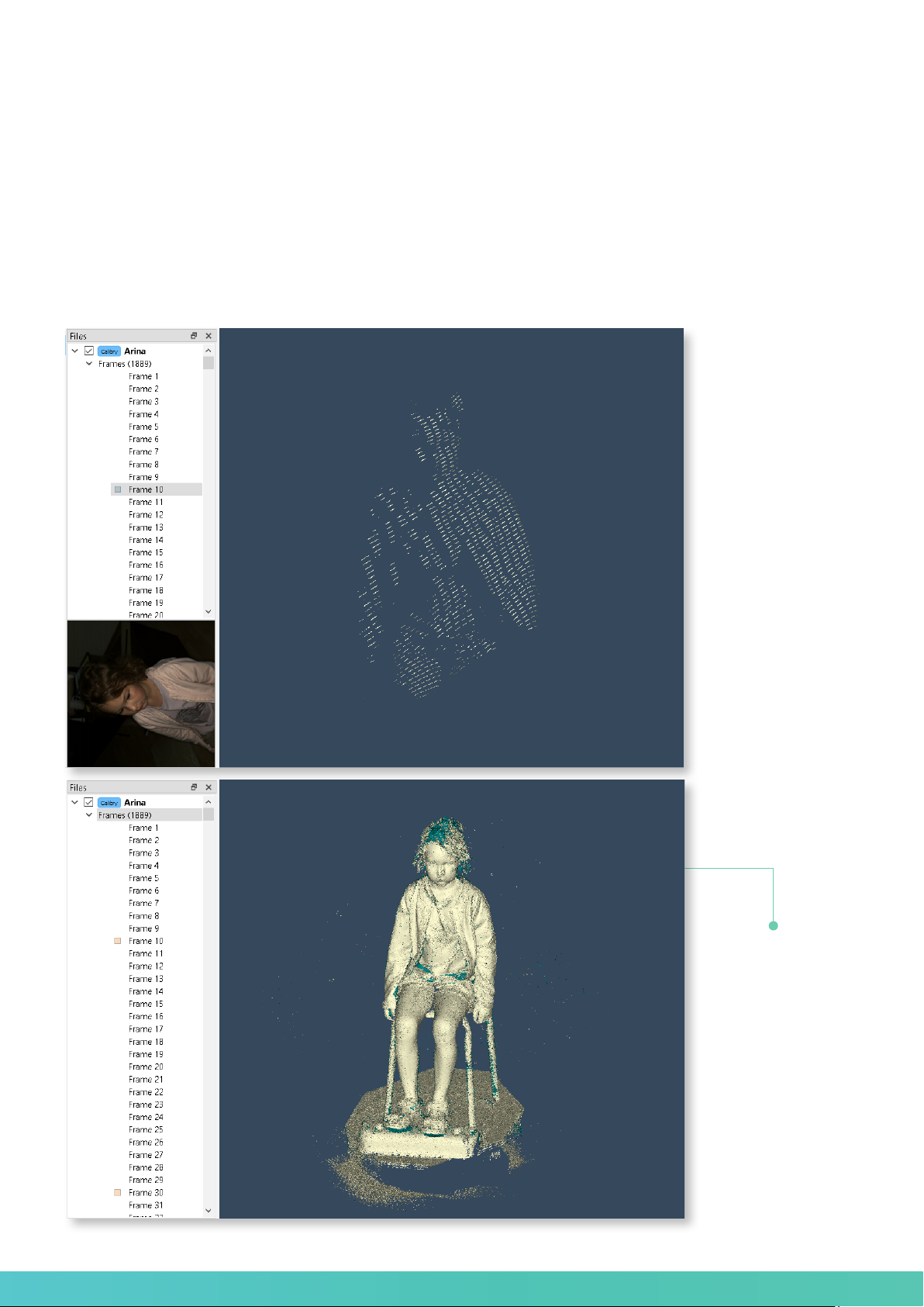
Raw data from scanning represents a set of frames captured by the scanner and used for 3D
model building.
Most of the frames are geometrical. Each geometric frame contains a certain number of points
on the surface of the object being scanned. Raw data may also contain texture frames used
for textured model building.
30
30
All of the geometric
frames create a
cloud of points
from which the
3D model will be
created.
Page 33
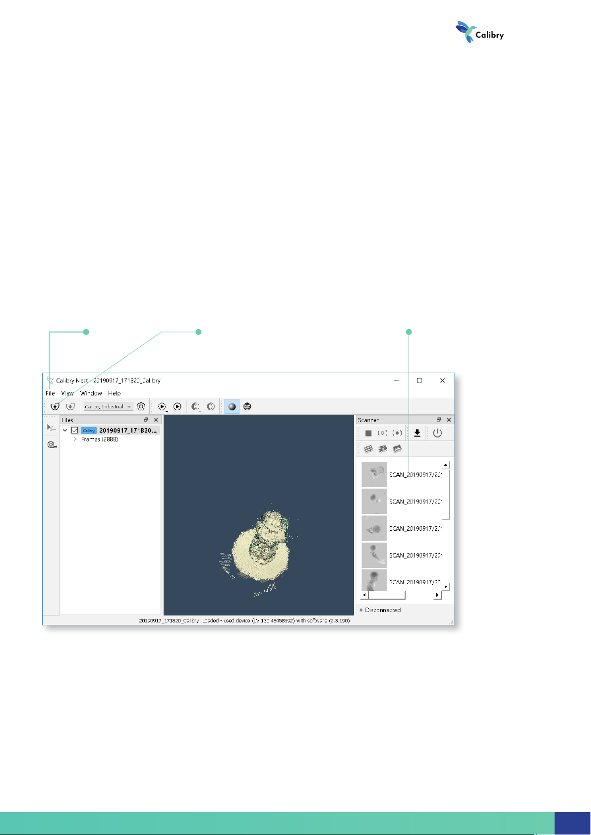
Apart from frames, raw data contain several les with additional information.
The data set described above is written into a le with .ascan extension, also
called a project le.
Opening a Project File
To begin working with a project you should open it using one of the following
methods:
1. Click Open project in the toolbar and select «project le» in the standard
dialog box
2. File -> Open menu;
3. Double-click the scan from the list in the Scanner window.
A project tree will be displayed in the Files window.
3D scanner
Menu File Open Project Scan from list
31
Page 34
Software manual
Data Visualization
A visualization window is used to view scanned data and the results of its processing. When working with data, a user can view:
• A cloud of points formed by one frame. Select the required geometric frame
in the project tree;
• A cloud of points formed by several frames. Select the respective geometric
frames in the project tree using Shift or Ctrl keys;
• A cloud of points formed by all frames. Click the Frames line located under
the heading line of the project with its name;
• Texture frames separately. Select the respective texture frame in the project
tree. Texture frames are marked in the project tree by beige boxes;
• 3D models obtained as a result of postprocessing.
When you click a project heading line with its name, the visualization window displays a cloud of points formed by one in ten frames from the project. To visualize a full cloud of points, click the Frames line located under
the heading line.
!
The 3D model in the visualization window can be moved, rotated and zoomed
out/in.
Moving – move the mouse cursor onto the model and hold both buttons simultaneously to relocate the model.
Rotating – move the mouse cursor onto the model and hold the left button
to rotate the model.
Zooming in and out – press and hold the right button and move the mouse.
Move it to the right or down to enlarge the model, to the left or up to shrink it.
Zooming in and out also can be executed using the mouse wheel.
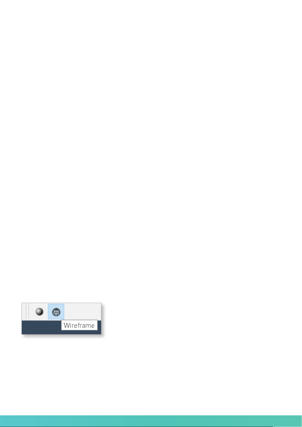
There are two types of 3D model display – as a texture or in the form of a polygon mesh. To make a selection, click one of the buttons in the View panel.
32
32
Page 35
Simple Postprocessing
Simple postprocessing is the name for data postprocessing when only one pro-
ject le is used for 3D model creation. This means that to obtain the model only
one scanning session was launched, i.e., the entire object has been scanned
once as a whole.
As a rule, simple postprocessing is used for scanning simple objects. Also, sim-
ple postprocessing can be sufcient when an object can be scanned from all
directions without changing its position. Scanning a human being is a typical
example of this.
In general, simple postprocessing includes three stages:
1. Registration;
2. Finalization;
3. Texture mapping.
Let’s consider each one of these three stages separately.
3D scanner
Registration
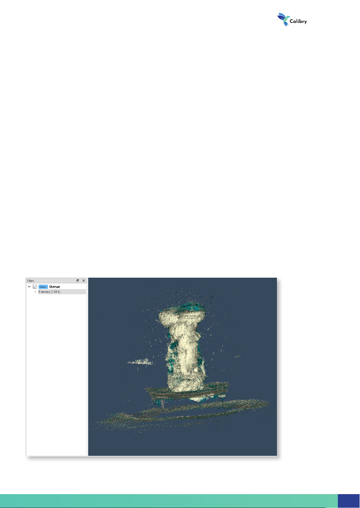
At the registration stage, raw data is processed by several algorithms which orient geometric frames relative to each other.
As a result, the complete cloud of points proves to be the closest to real surface
of the object being scanned.
Before registration
33
Page 36
Software manual
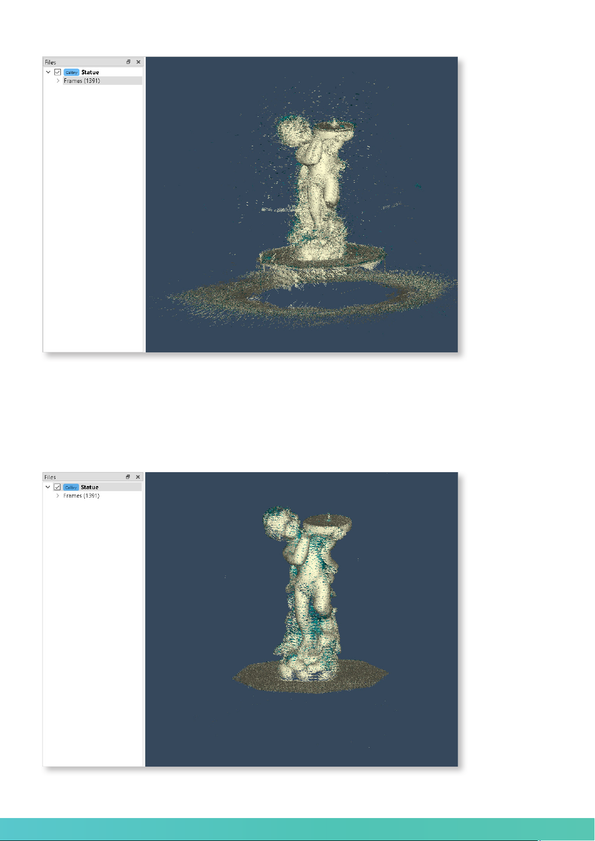
After registration
At the registration stage, a preliminary cleaning procedure can be executed
by specifying the corresponding setting. This procedure will automatically remove those points from the cloud that will be determined by the algorithm as
noise or other data not relevant to the object being scanned.
34
34
After preliminary cleaning
Page 37
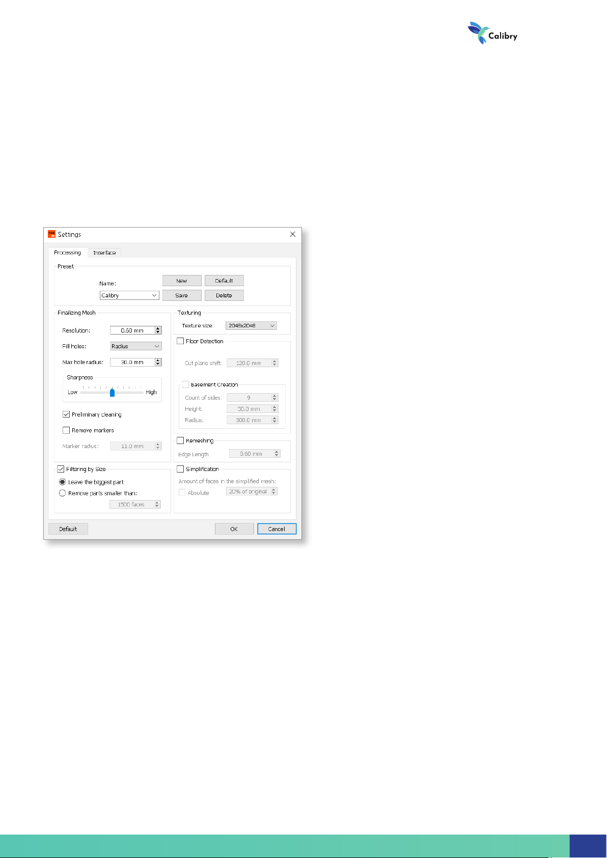
Finalization
At the nalization stage, the cloud of points is converted into a polygonal model. In
this case, it is necessary to specify certain algorithm settings.
In the top of the window you can select an array of preset settings depending on the scanner model and the scanned object. You can also create your own array of the most frequently used settings.
!
3D scanner
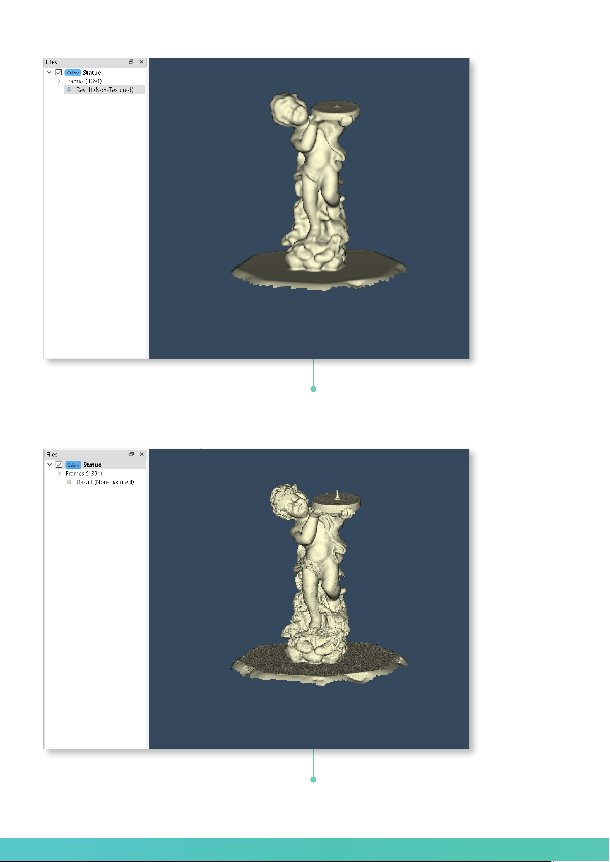
Resolution. This parameter determines the size of the face of elementary
polygons (triangles) which will constitute a polygonal model. The smaller the
size of an elementary polygon, the more detailed a model is. However, increasing the level of detail results in an increase of algorithm run time.
When Resolution parameter values are equal to or less than 1mm an algorithm requires more raw data which is achieved by increasing the period
of object scanning time. If there is not enough raw data, this can lead to
paradoxical results. Despite the specied high level of detail and long al-
!
gorithm run time, the obtained surface will be uneven.
35
Page 38
Software manual
The result of running the algorithm with a low resolution (4 mm)
36
36
The result of running the algorithm with a high resolution (0.7 mm)
Page 39
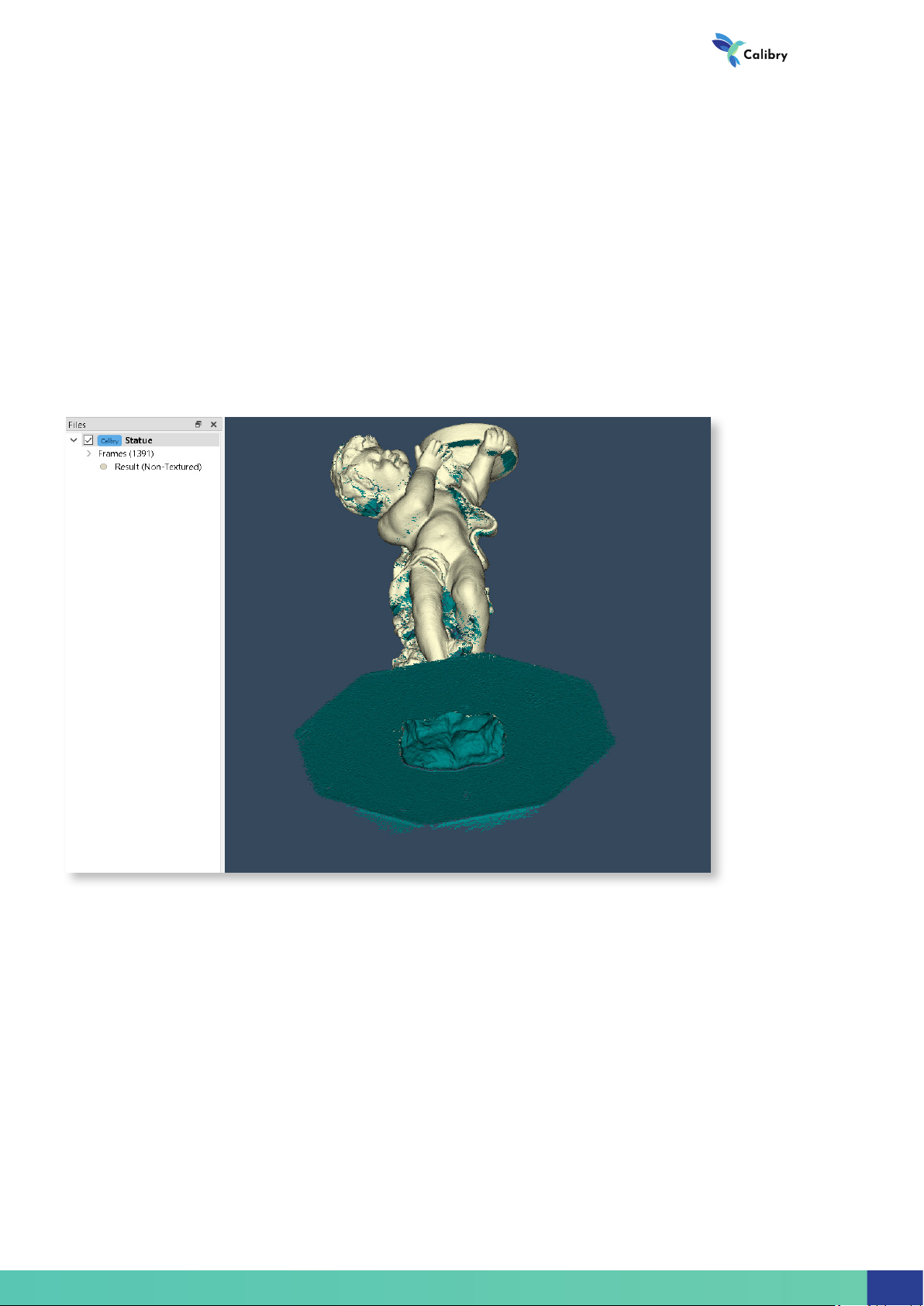
Fill holes. On the obtained surface of the 3D model, holes can appear. If the
real object being scanned actually has holes on its surface, this is normal. But
sometimes the holes are formed as a result of insufcient raw data. In this
case the situation can be corrected algorithmically at the nalization stage. All
holes can be lled on the 3D model (Fill holes = all). Also, only smaller holes can
be lled when their radius does not exceed a certain value (Fill holes = Radius
(__mm)). In this case it is assumed that all larger holes are real voids in the surface of the object being scanned.
In the example below, the Fill holes = Radius (0.5mm) parameter is not chosen
correctly. On the resulting model there are holes with sizes exceeding 0.5mm.
A larger hole radius for lling should be specied.
3D scanner
37
Page 40
Software manual
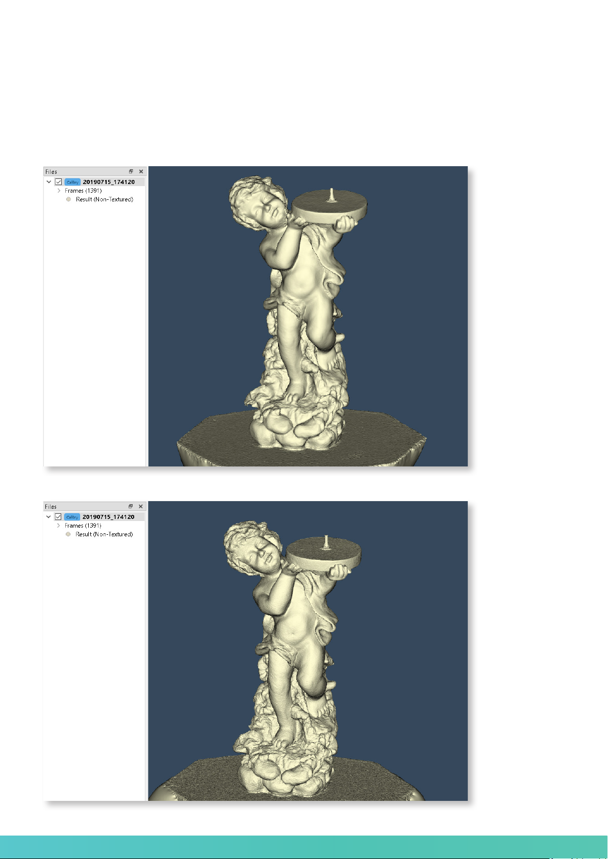
Sharpness. This parameter determines the appearance of the polygon mesh.
At a low level of sharpness, the polygons are merged more smoothly, without
sharp angles, while high sharpness makes geometry more detailed and thus
the image becomes more clear.
38
38
Page 41
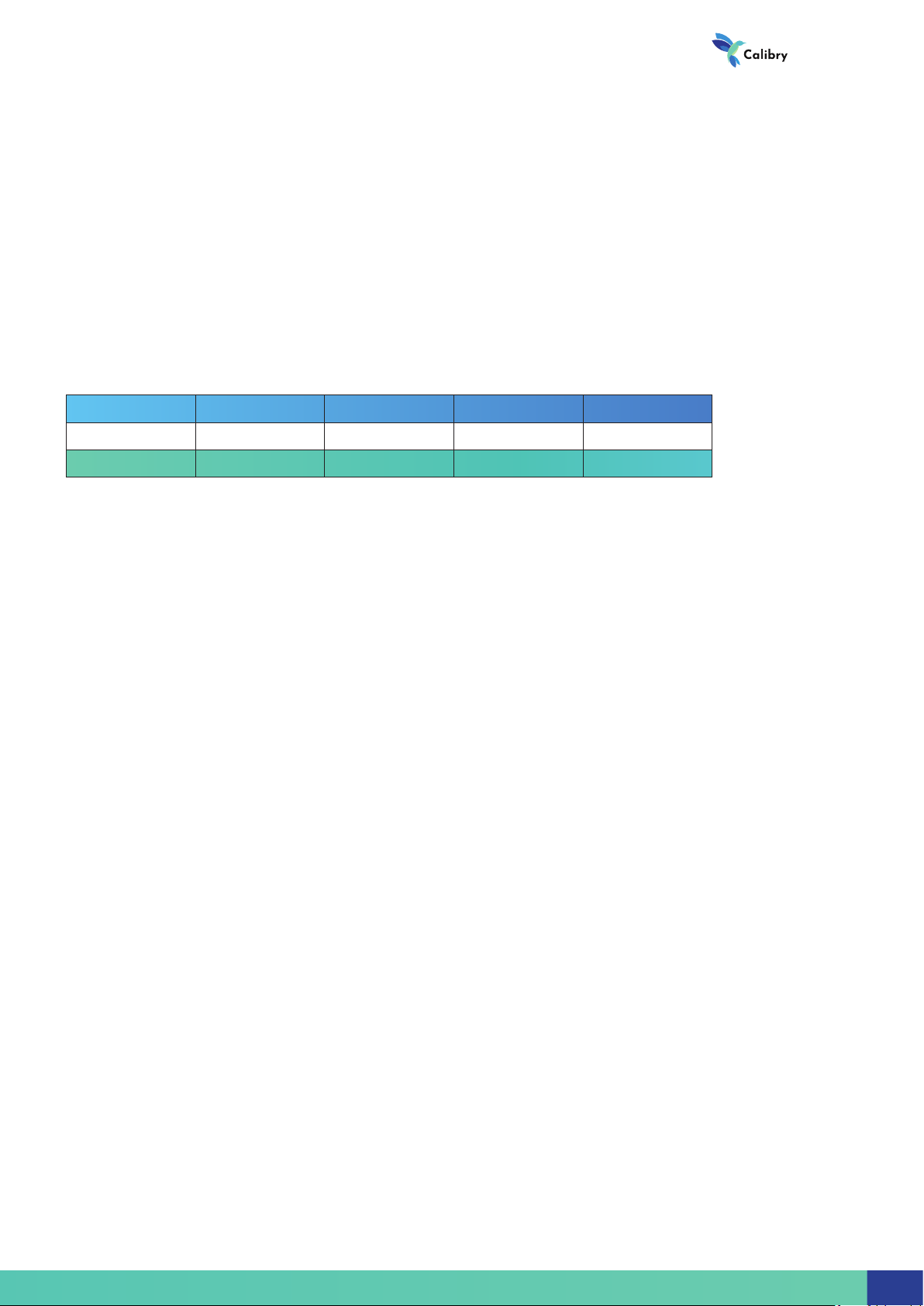
Additional procedures which can be executed at the nalization stage.
Remove markers. Use this procedure only when the scanning was made in
marker tracking mode. Put a tick against Remove markers and choose marker
radius in order to remove it from object geometry. This parameter can vary
depending on the model of your scanner, as well as on marker type: markers
can be both magnetic and printed by you on the printer.
Markers are not removed on the texture
!
Calibry DRAKE Maxi DRAKE Midi DRAKE Mini
Round 12 mm 12 mm 6.5 mm 3.5 mm
Square 15 mm 15 mm 7.2 mm 4.0 mm
3D scanner
The algorithm automatically identies all markers on the surface, removes
them and lls newly formed holes. If markers are in areas of the surface with
nonuniform geometry, the holes may be lled incorrectly. Therefore, when
placing markers, it is recommended not to overrun the perimeter of an ob-
ject, as well as to avoid an area with signicantly large geometry.
Filtering by size. The ltering algorithm removes noise and extra objects
which could fall into the eld of scanner vision in the process of scanning.
When the Leave the biggest part option is chosen all smaller objects as compared to the largest one will be removed. When the Remove parts smaller
than option is chosen the algorithm will remove objects that are smaller in
size than the selected value (in polygons).
39
Page 42
Software manual
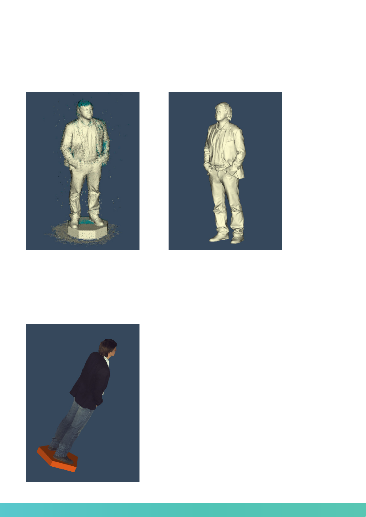
Floor detection. The procedure automatically recognizes and cuts the oor
surface. Cut height is counted from the oor and is specied according to
how the model has been scanned. When the Thor3D rotary table is used the
parameter of 150 mm should be set, when scanning is executed without this
table the value of 5 mm should be set.
Basement creation. After the oor has been cut, an arbitrary basement for
the model can be created. The Count of sides parameter species the number
of faces in a generated basement, and Height and Radius parameters specify
the corresponding height and radius of the basement in millimeters.
40
40
Page 43

Remeshing. The calculated 3D model consists of multiple triangles. In gener-
al, the lengths of triangle sides can differ greatly. For some CAD applications,
it is much easier to work with models which consist of identical triangles. For
this purpose, a remeshing procedure is used. Specify the required length of
the triangle side (Edge Length) as an additional parameter.
If during the remeshing process the Edge Length parameter greatly exceeds the resolution of the 3D model, the level of detail of the new model
will decrease. But if the Edge Length value is lower than the 3D model
resolution then the size of the new model and its processing time will in-
!
crease.
Simplication. The mesh of the resulting model may not be optimal for
some applications because it contains too many polygons. This can make
its further processing more difcult. In order to optimize a model with minimum degradation of accuracy the simplication algorithm can be used. The
value of Amount of faces in the simplied mesh species the extent of ge-
ometry simplication. (Example, if the initial model has 1,000,000 polygons,
then reducing it to 20% of the original will yield a model which consists of
200,000 polygons). By checking the Absolute (Absolute value) parameter you
can specify the number of polygons in the nal model. Resulting model detailing will vary depending on the specied number of polygons. The more
polygons used, the more detailed the 3D model will be, but at the same time,
more time will be required for its processing.
3D scanner
Texture mapping
Calibry scanners are equipped with a color camera which allows you to take
images of three-dimensional surfaces with texture. Texturizing is performed
by projecting separate captured color frames onto a nished 3D model. The
Texture size can be specied manually by choosing one of three provided options: 1024 × 1024, 2048 × 2048 or 4096 × 4096. The larger the size, the more
exact and sharp the result will be, and, accordingly, the more time required
for 3D model processing.
It is recommended to use simplication prior to texture mapping. Simplication signicantly reduces the time of texture mapping.
!
41
Page 44
Software manual
Simple Postprocessing – Generalized Algorithm
Steps in italics are optional.
1. Registration
1.1. Preliminary cleaning
2. Finalization (Resolution, Fill holes, Sharpness)
2.1. Removing markers [Marker size]
2.2. Filtration by size [Leave the biggest part / Remove all parts smaller
than...]
2.3. Floor detection
2.3.1. Basement creation
2.4. Remeshing [Triangle leg size]
2.5. Simplication [Percent of initial model / Number of triangles in
new model]
3. Texture mapping [Texture size]
When any postprocessing procedures are executed, the Calibry SW cannot execute other operations. Scanning, opening and processing other
projects, etc. are impossible. Wait for completion of the current postprocessing procedure in order to proceed with new operations.
!
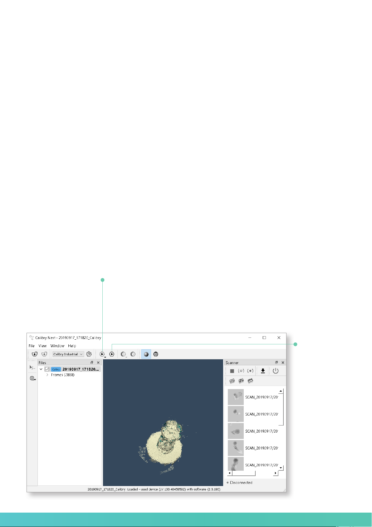
To start simple postprocessing without texturizing press
F5 or click Start – Non-Textured. By holding the button
pressed for a while, you can separately launch registration
and nalization procedures.
To start simple
postprocessing
with texturizing
press F6 or click
Start – Textured.
42
42
Page 45

Multiple Postprocessing
To build 3D models of certain objects, it is sometimes necessary to execute
several scanning sessions. Most frequently, this is necessary to scan an object
from all directions. E.g., scanning an object from above and then turning it
over and to scan from below. As a result, it is necessary to assemble the 3D
model in several parts.
Multiple postprocessing is data processing where several project les are
used to build a 3D model.
In general, multiple postprocessing algorithms are as follows:
1. Simple postprocessing each separate part of an object;
2. Alignment parts of an object;
3. Multiple registration;
4. Multiple nalization;
5. Multiple texturizing.
3D scanner
Alignment parts of an object
Alignment consists of positioning of several parts of an object into a single
entity. For this purpose, object parts should have common points. This must
be taken into account during scanning. If two parts of one object do not have
intersecting areas it is impossible to align these parts.
You cannot align textured parts with non-textured parts. You cannot align
object parts scanned with marker tracking with parts scanned without
the use of markers.
!
Points located on both of the aligned parts can be specied manually. There
must be a minimum of three points. You can specify more than three points,
increasing the probability of high-quality alignment. This is called manual
alignment.
If the scan was created using tracking by markers, several scans can be
aligned automatically (no need to identify three of the same points on differ-
ent scans). This is called automatic alignment.
For automatic alignment using markers, all object parts should be scanned
in marker tracking mode. When postprocessing each object part, the
markers should remain on these parts. Do not cut out the markers at the
postprocessing stage of object parts.
!
43
Page 46
Software manual
Automatic alignment
For simplicity, at rst let’s consider the procedure of automatic alignment an
object of three parts by markers.
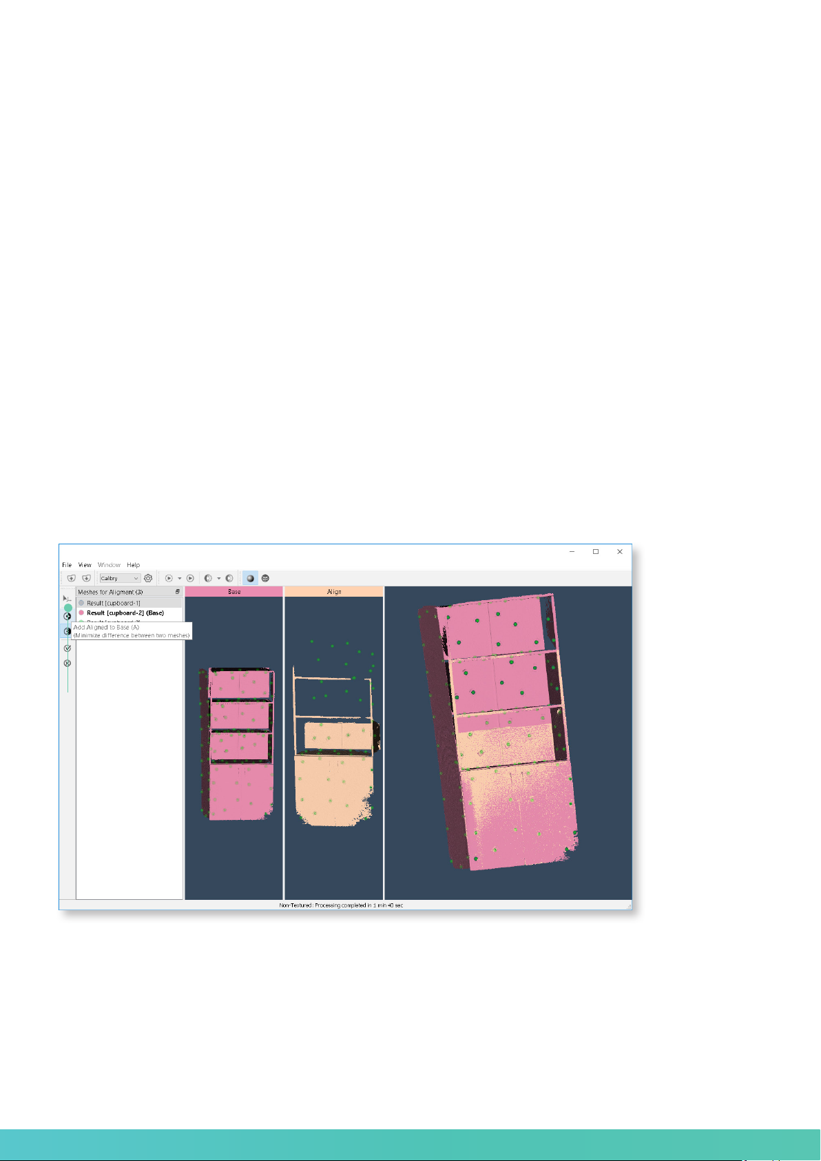
In the project window, highlight the 3D models of all components to be
aligned and click Alignment by points. The alignment window will appear.
The working alignment window is divided into three parts:
1. Basic window. There is part of the object selected as a base to which all oth-
er parts of object will be aligned to;
2. Alignment window. Here the part of the object is displayed that is aligned
to the base in current iteration;
3. Result window. Here the result of alignment is displayed.
In order to change the scan which will stand for the basic one, right-click
it in the scan list window (Meshes for alignment) and select «Set base».
To change the position of the basic window and the alignment window,
simply drag-and-drop them using the left mouse button.
!
If the model in the result window looks acceptable then click Add Aligned to
Base.
44
44
Page 47
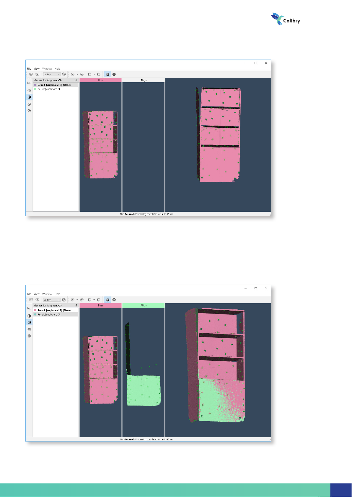
Eventually, the resulting model consisting of parts #1 and #2 will be displayed
in the basic window, just like in the result window.
3D scanner
We need to «stick» the remaining third part to this model. To do this, left-click
it in the scan list window (Meshes for alignment). The third part of the object
will appear in the alignment window and will be ready to be aligned with the
base.
45
Page 48
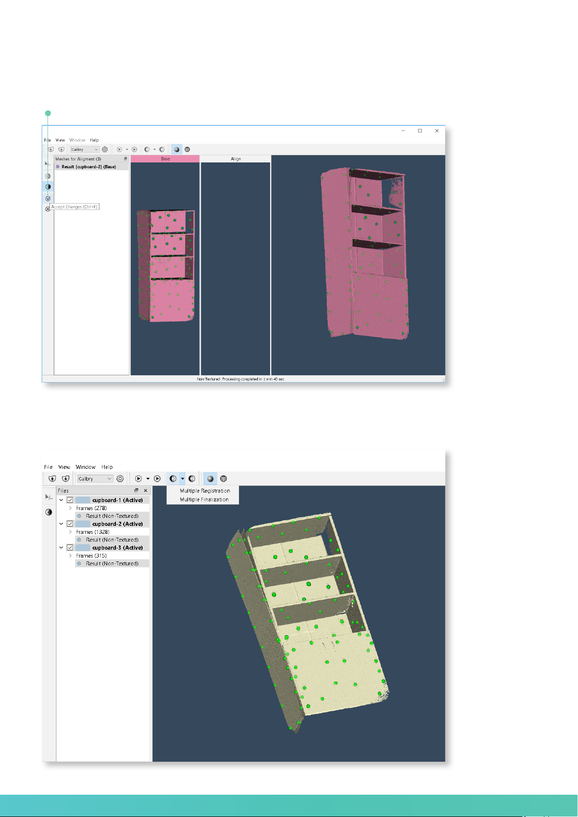
Software manual
Click Add Aligned to Base once more. The other parts of the object can be
added to the base model in a similar way until all of them «stick» to the base.
When all parts are aligned together click Accept Changes.
The complete point cloud of an aligned model will be displayed on the screen.
46
46
Page 49
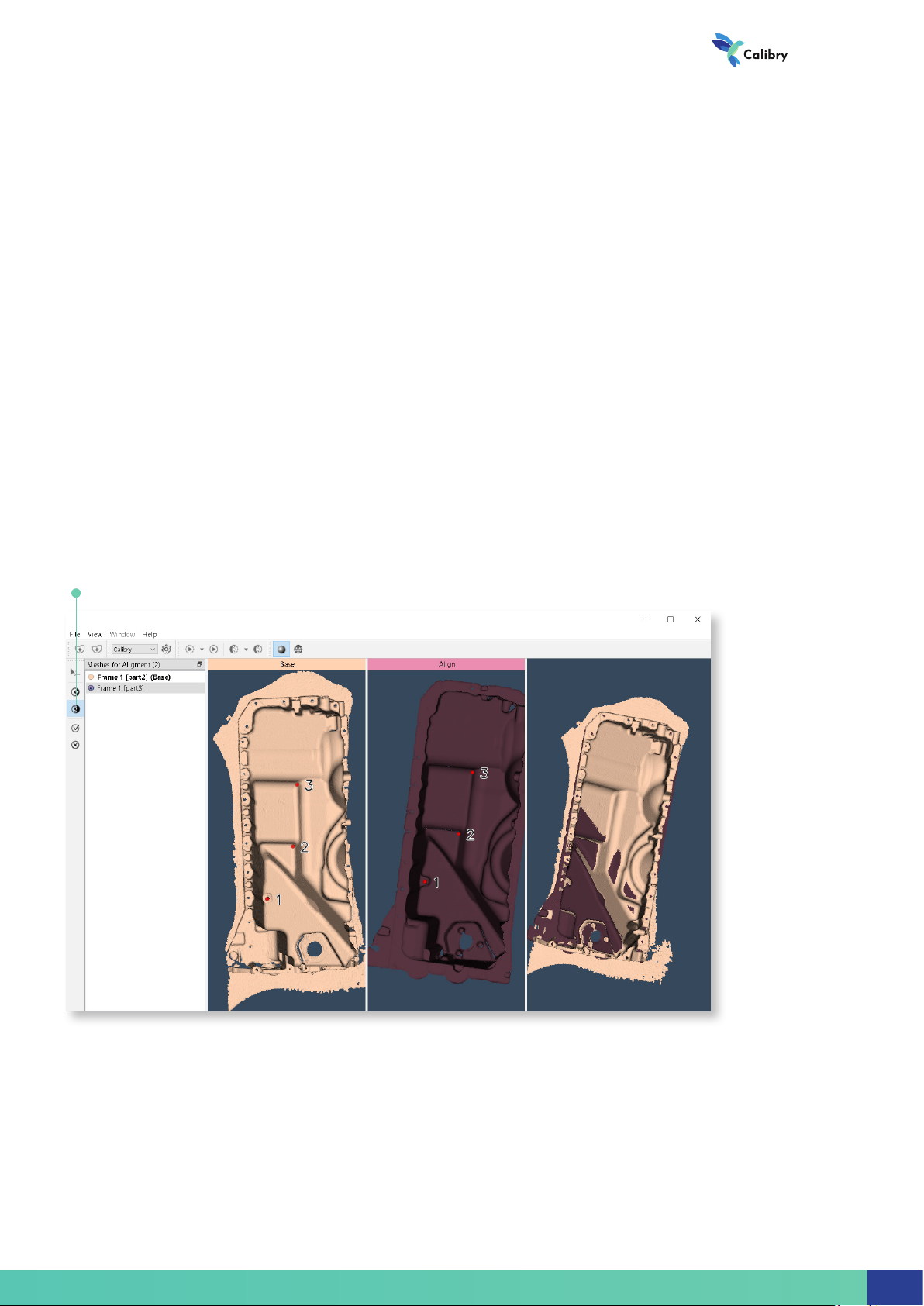
Everything is ready for starting up multiple registration and multiple nalization procedures. The intent of these procedures, as well as settings applied are
similar to the relevant procedures for simple postprocessing. The difference is
only in that for their execution the data obtained in several scanning sessions
is used together. The multiple postprocessing procedures starting panel is
similar to the same panel for starting procedures of simple postprocessing
and is located to the right of it.
Prior to starting multiple postprocessing procedure be sure to select the
projects from which nal 3D model is assembled. Data from projects not
marked by tick will not be used in multiple postprocessing procedures.
!
Manual alignment
If object parts were scanned in tracking by geometry and/or by texture mode,
then you must specify the common points which are present on parts to be
aligned.
Make 3d models of the parts being aligned and click Alignment by points.
3D scanner
Select the common points on the base and align scans.
It is recommended to choose common points in areas which are easily
identiable by specic geometric or textural features. This will allow the
algorithm to minimize the difference in location of the same point on the
base and the model to be stuck.
!
47
Page 50
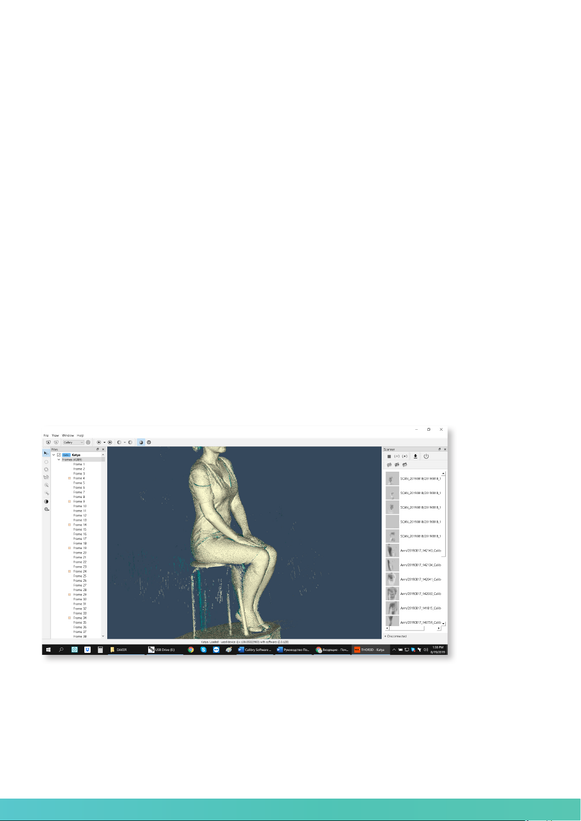
Software manual
To place an alignment point, double-left-click it rst on the base and then on
the second model. Specify a minimum of three alignment points.
Double-click a point to remove it. Press and hold CTRL key and move a point
to relocate it.
If you like the result which you see in the result window, click Alignment by
points.
Further actions are similar to 3D model assembling in automatic alignment
mode.
Additional Processing Tools
Raw Data Processing
Raw data is presented in the program as a list of textural and geometric frames.
When selecting one or more frames, you can see the respective raw data which
can be edited using tools on the left panel or deleted. These tools are available to correct issues that might have occurred during scanning. For example,
when scanning a human being, even a small difference in facial expression can
lead to a blurred texture or geometry divergence. In this case, bad frames can
be deleted or the face area can be cut out from them.
In the example below geometry divergence can be observed; the scanned
model shows splitting of the surface of the leg.
To search for bad frames, use data visualization. Click the frame in the tree,
press Shift, then press the up or down arrows to highlight new frames.
Frames can also be highlighted by rotating the mouse wheel. In the visualization window, you will see a cloud of points to which subsequent frames
will be added each time. Thereby, once bad frames have been highlighted
this can be seen.
48
48
Page 51
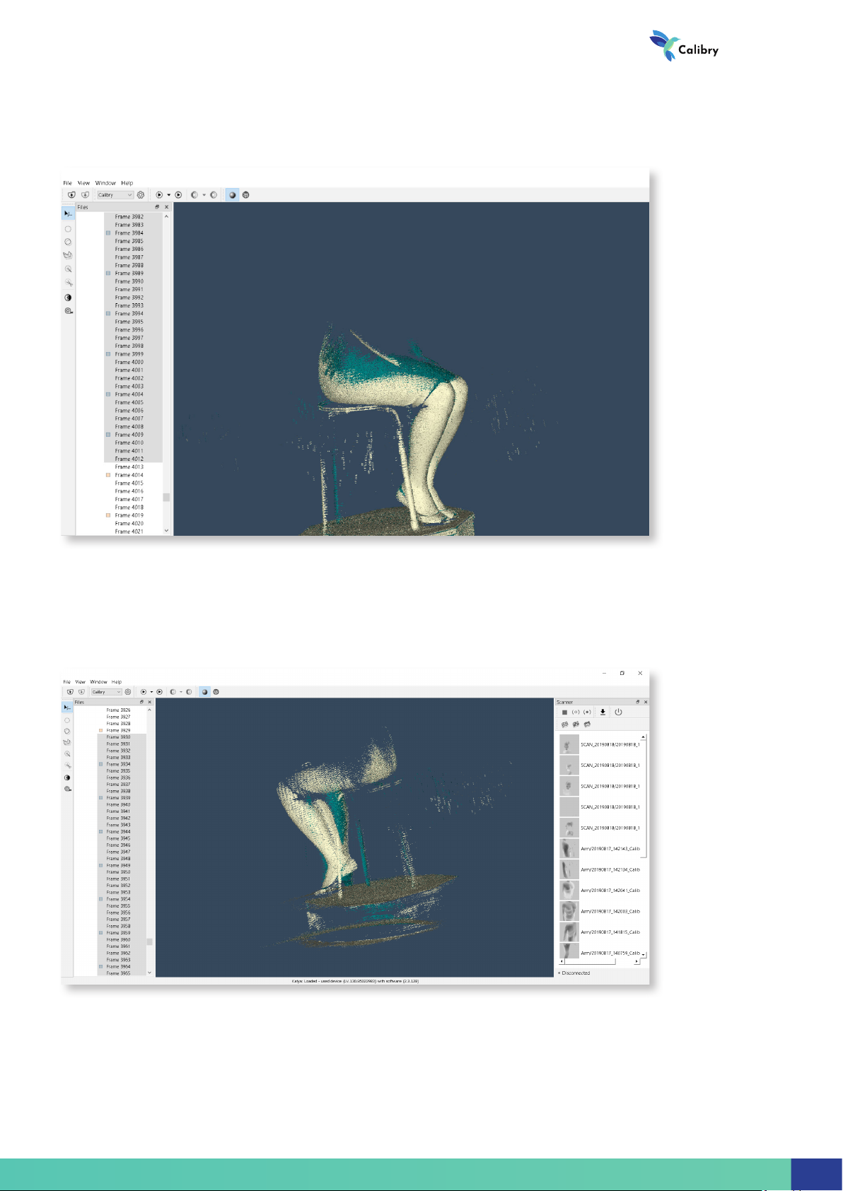
In the context of our example, let’s begin to highlight frames starting from
the very rst. Having added more than 4000 frames to selection we see that
divergencies in leg geometry are still not present.
3D scanner
Now let’s begin to review frames from bottom to top starting from the last.
From a certain moment (approximately from Frame #4050) the leg starts to
split.
Therefore, we can conc lude t hat in fr ames ## 0 –4050 th e l eg sur face is map ped
correctly. After this, the leg has probably moved. Therefore, in frames ##4051–
4455 the leg surface begins to recover differently, and its splitting appears.
The situation described above can be corrected in several ways.
49
Page 52

Software manual
Deleting Bad Frames
In the context of the relevant example, it can be noted that the 3D model is
obtained even without the last group of frames which cause the splitting of
the leg. Therefore, all the frames starting from #4051 onward can simply be
deleted.
Highlight bad frames, right-click them and choose Delete in the drop-down
menu.
Project Fragmentation
In the example under our consideration, there are not many bad frames. We
have 4050 frames left for further postprocessing and have deleted at worse
around 400 frames.
However, in some cases divergencies in geometry can be xed as early as in
the middle of a scanning session. For instance, some part of the model surface in frames ##0–1000 has one spatial orientation, and in frames ##1001–
2000 – other orientation. When half of project frames are deleted there will be
insufcient raw data. In this case, you can try to divide the project into several
parts (perform fragmentation). Right-click the required frame and choose Di-
vide project in the drop-down menu. Then try to assemble the 3D model with
parts from several projects.
In the context of relevant example, it is possible to try to divide the project
into two parts: ##0–4050 and ##4051–4455. If splitting of the leg surface
was caused not by its movement but by inaccuracies in algorithm work
then, with a high likelihood ratio, the nal 3D model will be correctly built
of two parts. If leg movement during scanning nonetheless took place,
!
then there is no need to divide the project into two parts as, with a high
likelihood ratio, the leg shape in frames ##0–4050 and ##4051–4455 will
differ.
Editing Frames
When one or more geometric frames are highlighted in the project tree the
tool bar appears on the right.
Highlighting brush. Move the marker over the cloud of points formed by
frames. The points affected by the tool are colored red. You can change marker size by rotating the mouse wheel.
Polygonal lasso. The same as Highlighting brush, this is a selection tool. Only
the area of selection differs – it is determined by polygons where the shape
and size are chosen by the user.
Delete selected. When this button is pressed, all highlighted in frames and
red points will be deleted.
50
50
Page 53
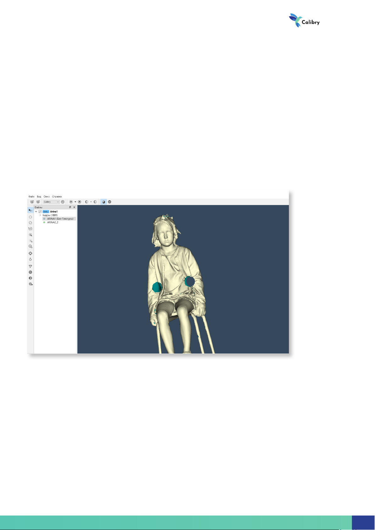
In the context of the relevant example, you can try not to delete frames
##4051–4455 as bad frames, but simply “erase” the leg image on them by
deleting the corresponding points from the cloud.
!
3D Model Processing
Left-click the 3D model resulting from postprocessing. To the right of the projects, the toolbar will be displayed.
Marquee Brush. Move the cursor over the model surface. The surface areas
affected by the tool are colored red. By rotating the mouse wheel, you can
change cursor size.
Marquee Double Side Brush. The tool differs from Marquee Brush by its
cross-section action. Thus, the tool acts not only on the surface over which
the cursor was moved, but on all surfaces under it.
3D scanner
In the above example, for the left hole the surface area has been selected by
the conventional Marquee Brush, therefore the hole was formed in that part
of surface which was touched by the tool. For the right hole, the surface area
has been selected by the Marquee Double Side Brush, therefore a through
hole was obtained.
Polygonal lasso. The same as the Marquee Double Side Brush, this is a se-
lection tool for cross-section action. Only the area of selection differs – it is
determined by polygons whose shape and size are chosen by the user.
Magic Wand. The tool for selecting the entire surface. This tool is convenient
for cases when the 3D model consists of several mutually separate surfaces.
Cut (Del). When the button is pressed all selected areas of the model surface
are deleted.
51
Page 54
Software manual
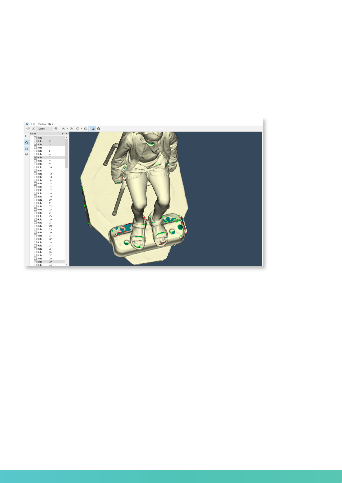
Cut on Frames. When the button is pressed all selected areas of model surface are deleted not only from the model itself but also from corresponding
frames.
Fill selected holes. When the button is pressed the list of all holes detected
by the algorithm on the 3D model surface is displayed in the project tree.
In the visualization window, holes on the model will be highlighted by a
green color. When corresponding holes are selected in the list its highlighting changes from green to red.
Click Accept changes for the algorithm to ll the selected holes.
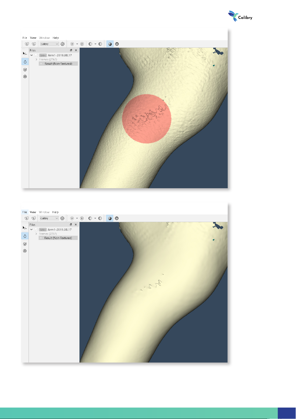
Smooth. Move the cursor with the left mouse button held over the model
surface to smooth it.
52
52
Page 55
3D scanner
53
Page 56
Software manual
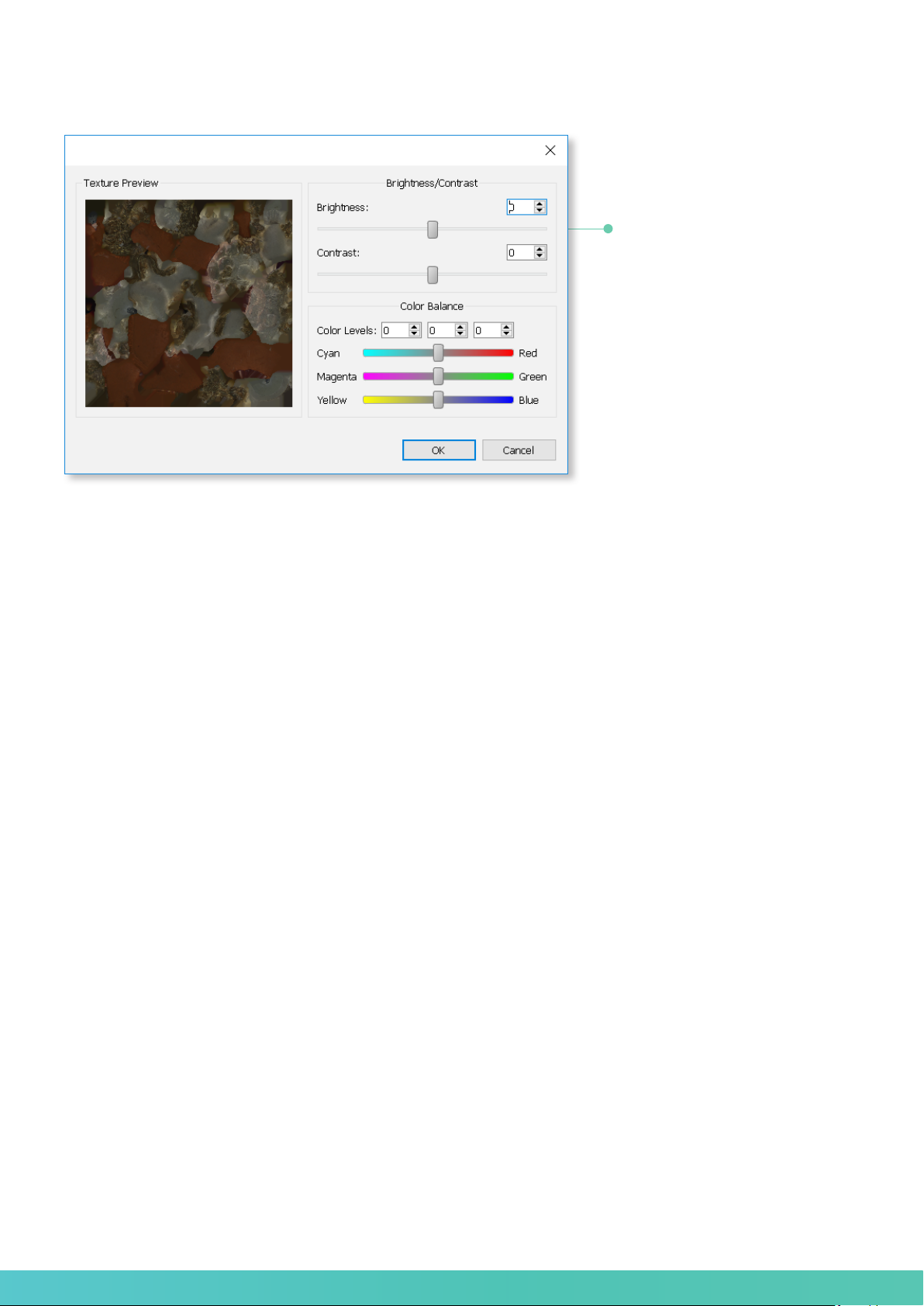
Texture correction. When this tool is selected this window appears:
Adjust brightness, contrast
and color balance using the
relevant sliders or numeric
eld settings. Click OK to
save your settings.
Luminosity brush. This is a tool for textured model processing. Move the
cursor over the model surface to increase texture brightness. To decrease
brightness (e.g., to delete glare from ash) move the cursor while holding
down the Ctrl key. Right-click to adjust brush strength and hardness.
The nished model can be saved in the required format separate from a
project.
54
54
Page 57
Other Calibry SW Capabilities
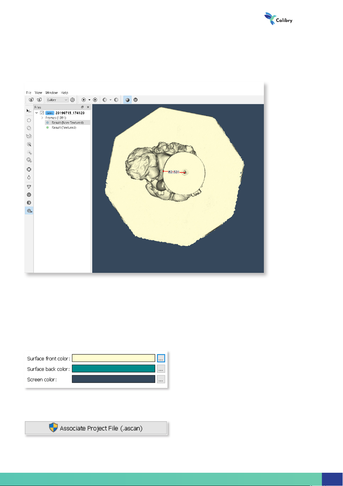
Ruler
Enables you to measure the distance in millimeters between two selected
points in frames or on a model.
3D scanner
Interface
The interface tab enables editing of user interface settings and includes the
following settings:
• Surface front color – color of polygonal model surface;
• Surface back color – color of polygonal model inner surface;
• Screen color – program background color.
Associate Project File – bind an .ascan extension to the program.
55
Page 58
Page 59

DRAKE
User manual
Page 60
Drake. User manual
Scanner
operation
To begin
To turn the scanner on, press the power button which is located under the
screen. Wait until the scanner loads and the main window appears on the
screen. The main window will contain:
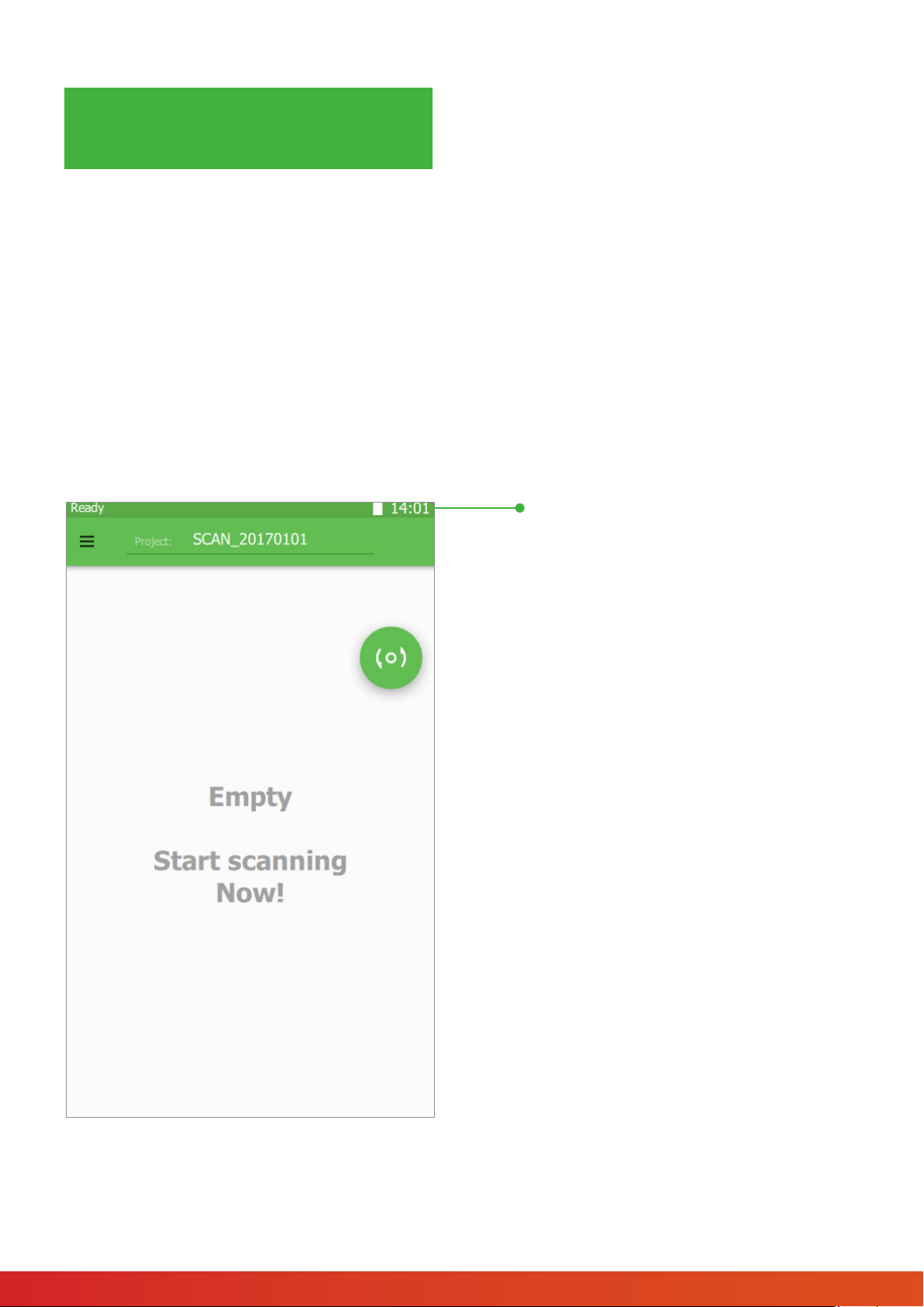
• Status Bar
• Control Panel
• Side Panel
• List of scans (if any)
• Main Thumb Control Buttons
Status Bar
The status bar will display the
current status of the scanner,
battery life, time of day, as well as
the strength of the Wi-Fi signal
whenever a Wi-Fi USB adapter is
plugged in.
58
58
Page 61
Scanner
operation
DRAKE
Control Panel
Here, you can change the name of your scan by
pressing the heading in the center. All objects
scanned will be placed in the folder with that
name. If the folder is not named, by default it will
be named like “SCAN_ 20170101” (Year, month
and date).
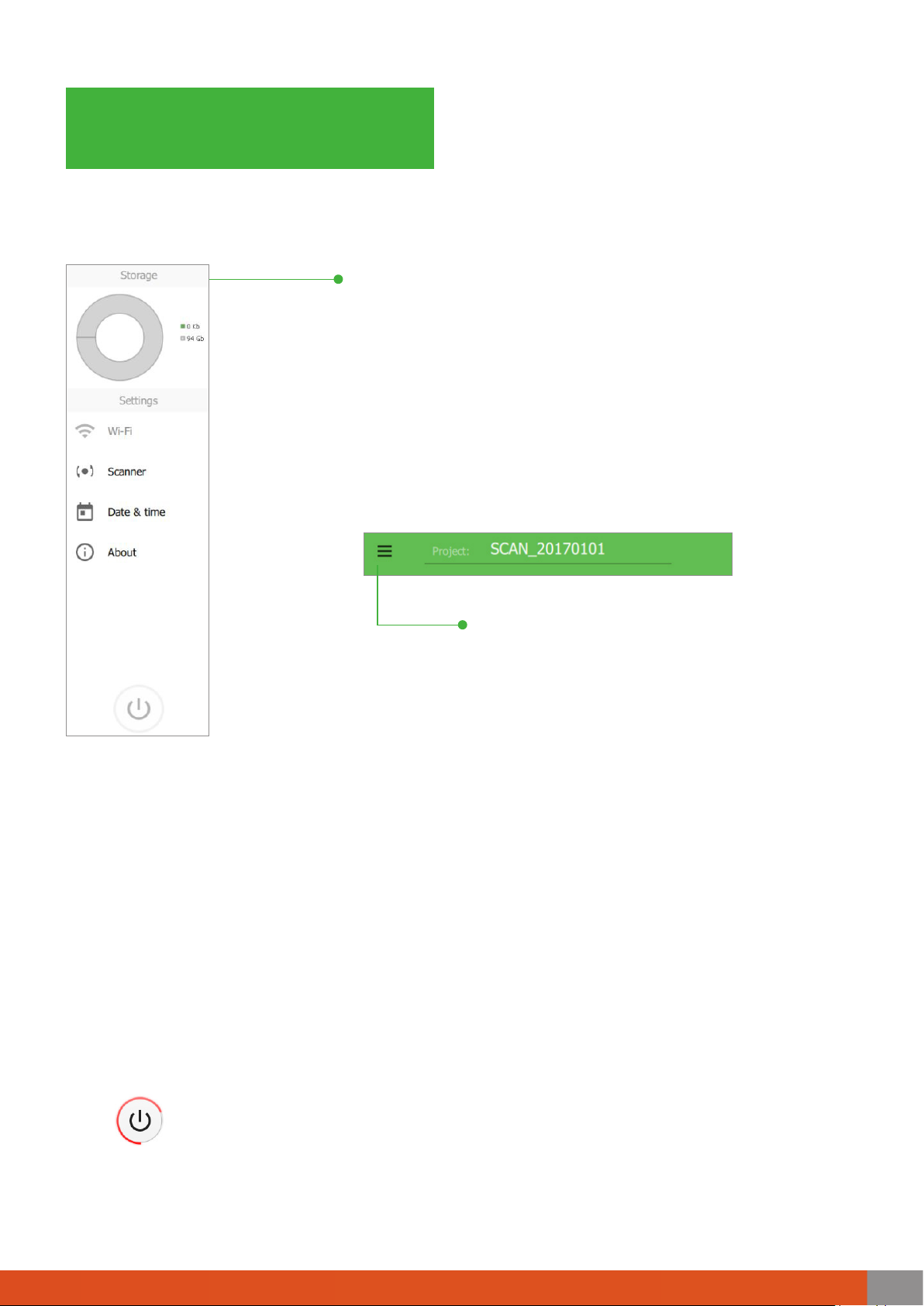
On the left, you will nd the
button, which when pressed will
open the side panel.
Side Panel
This side panel contains information on the memory available on the internal
hard-drive of the scanner, as well as available memory on the USB drive which
is currently plugged in.
Below that, you will nd the following menu items:
• Wi-Fi – allows you to connect to your local Wi-Fi network. It is available only
when a USB Wi-Fi adaptor is connected to the scanner.
• About – contains information about the scanner: model, serial number,
version of software, version of rmware, calibration number and calibration
version.
On the bottom of the panel, there is a “safe” off button. To properly turn the
scanner off, press and hold this button for two seconds.
For a hard-reboot, you may also press and hold the power button for two
seconds. This button is located on the scanner itself, under the screen.
59
Page 62
Drake. User manual
Scanner
operation
List of Scans
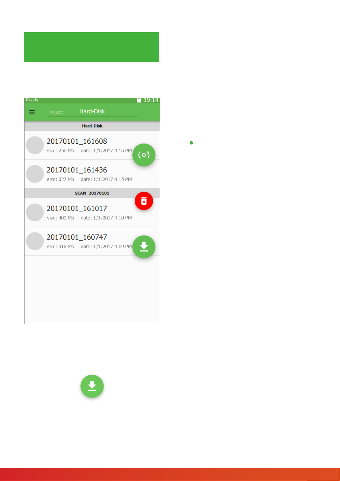
List of scans
The center of the screen is
devoted to the list of scans.
These scans are sorted by
date (the newest on top)
and are located in the
appropriate folder. There
is an icon next to each
scan, which represents
the rst frame captured.
You can switch between
folders (a.k.a. projects) at
any time by selecting the
appropriate section on
the screen or by creating a
new project by naming it
on the control panel above.
You can use any USB
drive (Flash, HDD) to save
your projects, preferably,
however, they should be
formatted for the NTFS le
system.
Once a USB drive is properly connected, you will see a new button on the
screen which will allow you to transfer the data from the internal hard-drive
of the scanner:
* To check whether you have enough space on your USB drive, as well as properly
eject the USB drive, go to the side panel.
60
60
Page 63
Scanner
operation
After pressing this button, your les will begin to copy, with the exception of
those that are already on the USB drive.
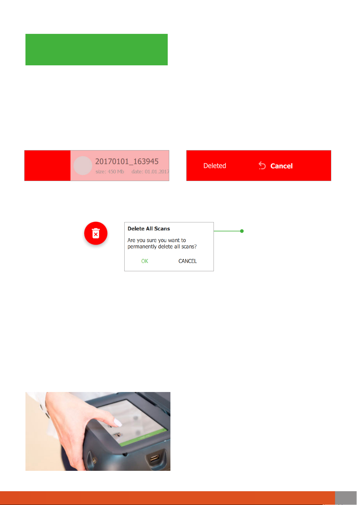
To delete any unnecessary scan from the hard-drive, simply swipe your nger
across the scan.
You can cancel any deletion within 5 seconds by pressing Cancel. To delete all
scans from the hard-drive, use the button:
DRAKE
Press OK to conrm
deletion of data.
Main Thumb-Control Buttons
The scanner is controlled via touch-screen. Use your right hand thumb, while
the rest of the hand supports the scanner. The main buttons are conveniently
located on the right side of the screen and can perform the following actions:
• Start Preview and Start Scanning.
• Stop Preview and Stop Scanning.
• Turn on/off «Marker» Mode.
• Delete all data on the scanner.
• Save all data onto a USB ash drive.
61
Page 64
Drake. User manual
Scanner
operation
Preview Mode
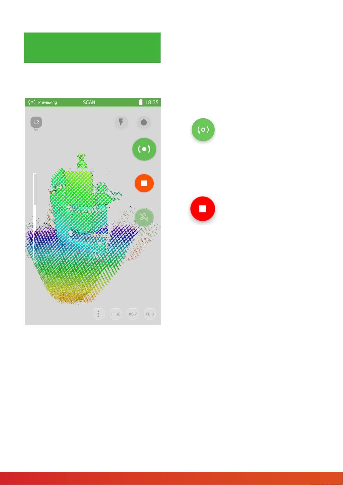
Turn on Preview Mode by
pressing this button.
Begin every scan in the Preview Mode. This
allows you to nd the right distance to the
object, evaluate the surface, and gauge whether there are enough markers (if scanning with
markers).
It is important to nd the optimal working distance between the scanner and the object. The
ideal working distance (also known as Depth of
View) depends on which set of lenses you are
using (Mini, Midi, or Maxi). For ease-of-use, the
object on the screen, in real-time, is shown in
different colors. If the surface is blue, you are
getting too far from the object. If it is red, the
scanner is in danger of being too close. The op-
To stop scanning press.
timal distance is shown in green, so try to keep
the scanner at that distance to the object during scanning. Another way to assess the correct
distance to the object is to use the white indi-
cator on the left side of the screen. The closer
you are to the object, the lower the bar will
drop. Try to keep the white bar in the middle
of the scale during scanning. Above this white
indicator, you will nd the real-time frame rate
information (FPS), as well as the number of
markers visible (if in «marker» mode).
62
62
Page 65
Scanner
operation
Marker Mode
To activate or deactivate «Marker» Mode toggle on/off the switch during Previewing:
While scanning with markers, it is important that each frame contains at least
3 markers. Because markers are identied in real-time by the software at up
to 12 times per second, not every marker will get identied in every frame.
That is why it is recommended to have at least 5 markers in each frame. So, 3
is the minimum, 5 or more is recommended. To monitor this, use the marker
indicator in the top left corner of the screen:
DRAKE
• If there are 4 or less markers in view – the indicator will turn red (the value is
critically low and tracking might be lost).
• If 5 markers are in view – the indicator is yellow (warning).
• If more than 5 markers are in view – green (all is good).
Scanning will automatically stop when tracking is lost (less than 3 markers
in view) and go back to Preview mode. You can nd a better position for the
scanner and start again. You will be able to automatically align all the scans
together in post-processing later.
Settings
Sometimes it is necessary to adjust settings for optimal scanning. To do that,
press the
button during Previewing. The changes will take effect in real-time, so if you
are pointing the scanner at the object, you will be able to understand when
these changes are optimal for your scanning situation.
63
Page 66
Drake. User manual
Scanner
operation
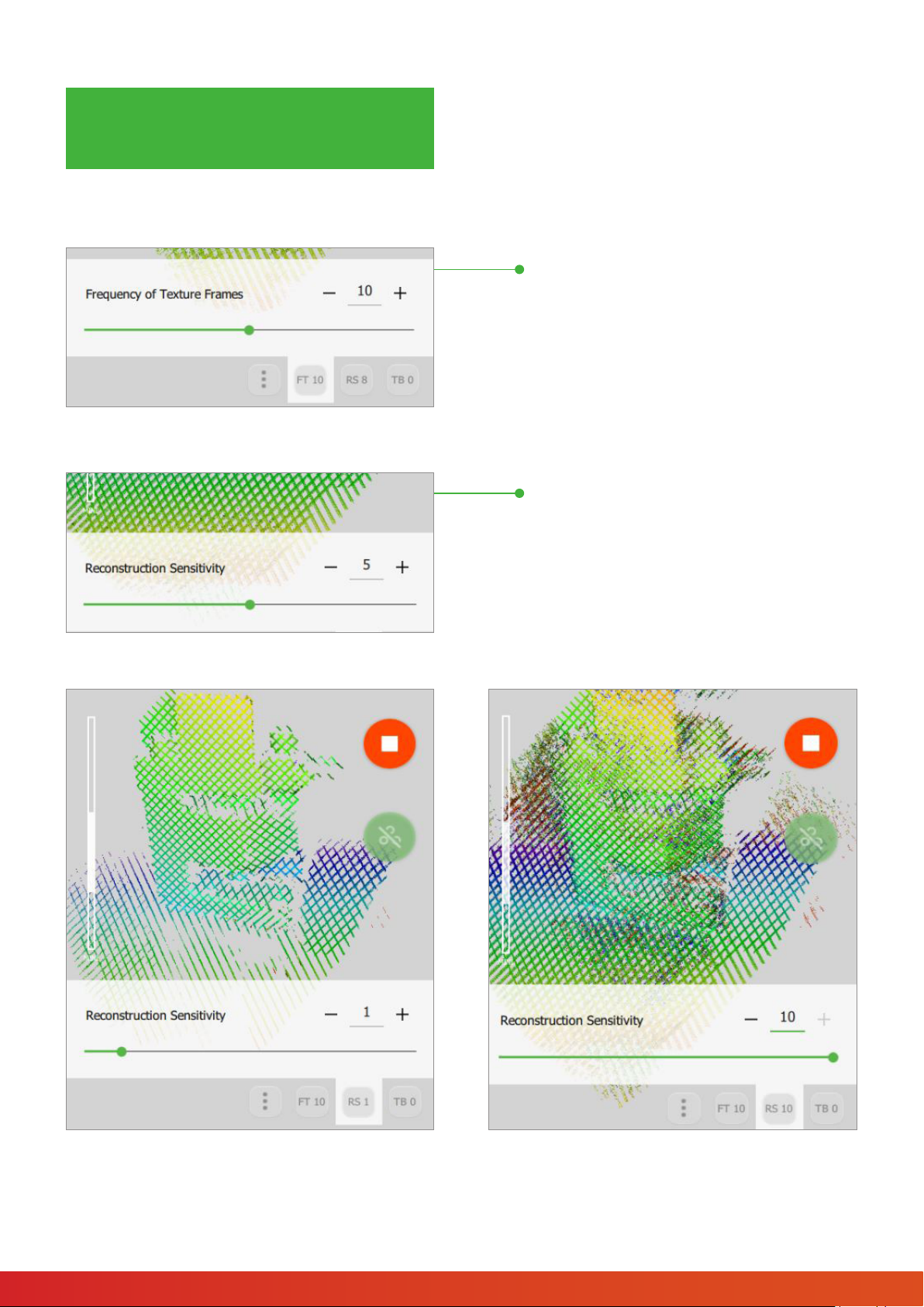
Frequency of Texture Frames
This parameter indicates with what frequency the recording of texture frames is
carried out. These frames are needed for
texturizing the nal model. The lower the
parameter, the higher the frequency and
thereby the higher the amount of texture
frames recorded. Setting the parameter
at 0 will turn the textures off.
Reconstruction Sensitivity
If during scanning there is a lot of “noise”
on the screen that means that either the
object is very dark (black objects are gen-
erally more difcult to scan than those
of lighter colors) or there is too much
ambient light in the room. To correct this,
try adjusting this parameter.
Increasing the value will increase the “sensitivity”, allowing the scanner to see more data, but
also increasing the amount of “noise”. Decreasing the value, will decrease both. The default
value is set to 6.
64
64
Page 67
Scanner
operation
Flash Indicator
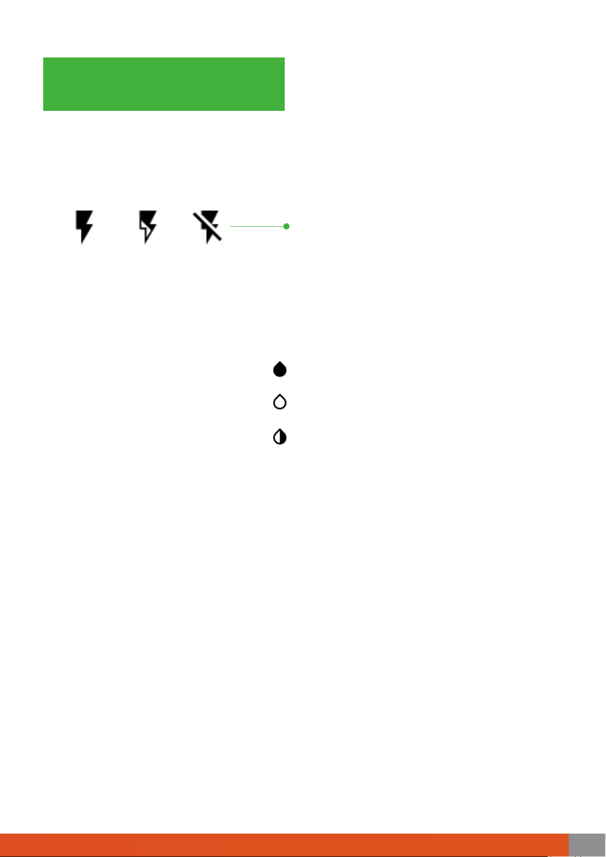
There are three modes for the power of the circular LED ash.
Circular LED ash
capacity
Full ash Half ash Flash light
turned off
Color mode
This feature allows you to capture black and shiny objects.
DRAKE
If the object is black use –
If the object is white use –
The default value of the color mode is
65
Page 68
Drake. User manual
Scanner
operation
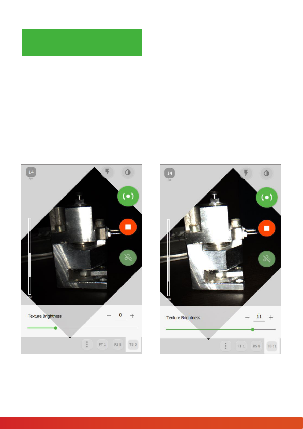
Texture Brightness
Make it higher or lower to make the texture more or less bright. This proves
especially useful for scanning humans as this setting helps achieve the most
natural-looking texture.
You also might like to leave the default value, and instead adjust brightness
when processing the model in Calibry Nest software.
66
66
Page 69
Scanner
operation
Wi-Fi Settings
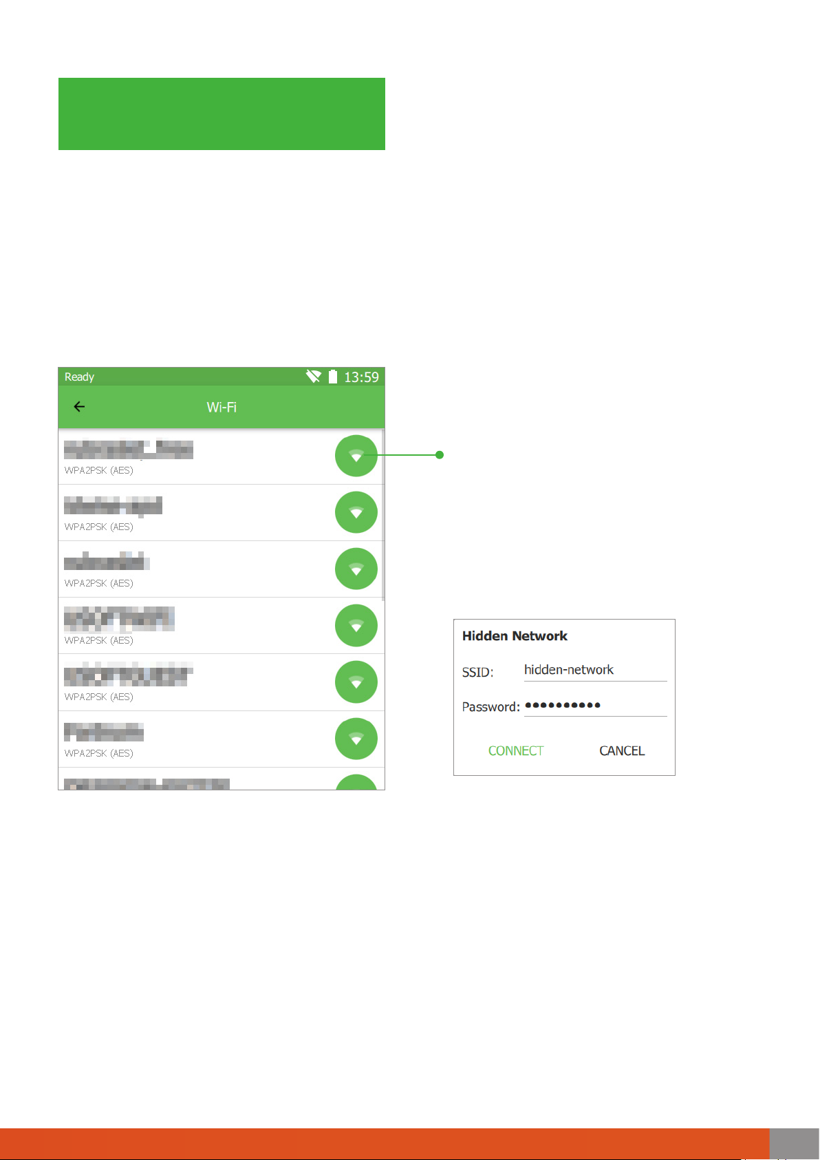
To enable wireless data transfer from Drake to a network computer via a local
Wi-Fi connection, rst plug in a USB Wi-Fi adapter. An indicator will appear
in the top right corner of the screen (an antenna with a line through it). This
indicates that the Wi-Fi adapter is plugged in, but not yet connected to the
local network. A list of available Wi-Fi connections can be found by selecting
the appropriate option on the side panel from the main screen.
DRAKE
Choose the network you would like to
connect to from the list. A pop-up dialog box
will prompt you to enter the Wi-Fi password.
Press CONNECT. If the network is hidden,
scroll to the bottom of the list and select
Hidden Network. Enter the name of the
network (SSID) and password and press
CONNECT.
After connecting, this network will be saved and you will not need to enter
your credentials again in the future. This network will now be rst in the list
of networks and when connected, an indicator signal strength will appear in
the status bar.
* Aside from a Wi-Fi USB adapter, you can also be using an Ethernet USB adapter to
connect to a local network.
Find the scanner under “Network” on any computer that is also connected to
the same network. Look for a device called “THOR” and after transferring the
data from the scanner, look for it in a folder by the name of “Scans”. For quick
access, press WIN+R: \\THOR\Scans and create a shortcut to this folder.
* Data transfer speeds over Wi-Fi depends on the type of network equipment you
have installed.
67
Page 70
Drake. User manual
Scanner
operation
Calibration of the scanner
Manual calibration
The Drake 3D scanner is a precise measurement instrument and is factorycalibrated. In order to ensure high accuracy of every scan, Thor3D has a
calibration procedure that the user can perform himself.
Preparation for calibration
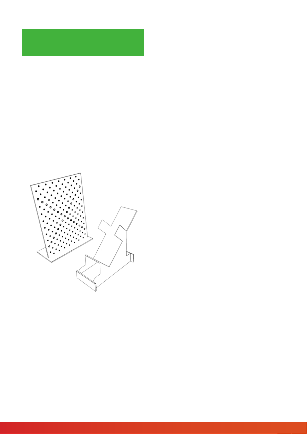
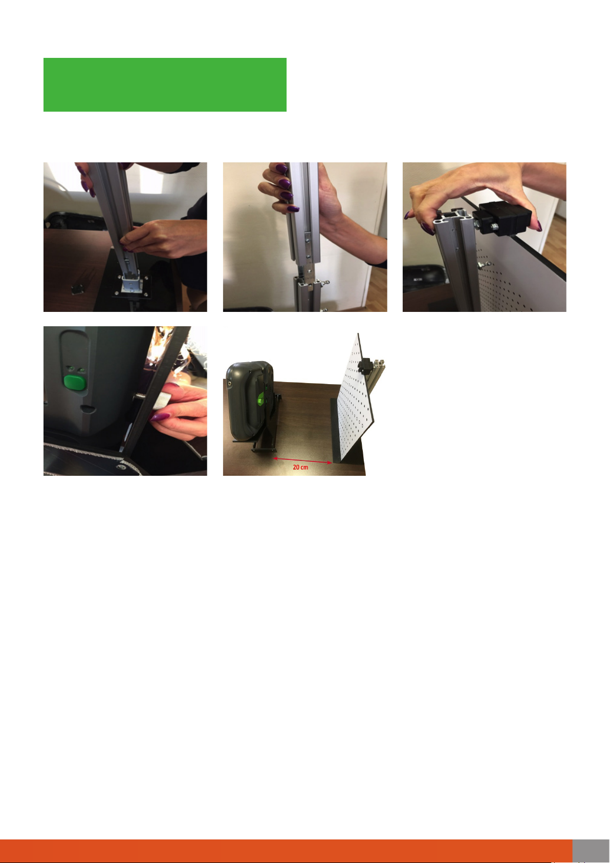
To calibrate the scanner, unpack the calibration stand and assemble it.
Attach the pole to the base
Attach the correct board to the base and the pole.
Ease the scanner into the stand and secure it by screwing in the tripod mount
at the base of the device
Place the stand with the scanner approximately 20cm (8in) away from the
board
You are ready to calibrate.
* Board will vary depending on which lens is being calibrated.
68
68
Page 71
Scanner
operation
Calibration of the scanner
DRAKE
Calibration procedure
To begin calibration procedure, turn on the scanner and open Side Panel.
• Select “Scanner” and “Calibration”
• Press “Start”
The device will start to scan and the screen will prompt you to move into the
rst position. To place the scanner perfectly in the rst position, follow the
prompts on the screen.
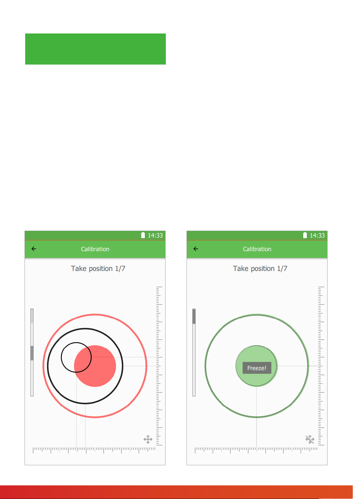
The scanner needs to be aligned in three ways:
1. Find the correct distance to the calibration board by moving the stand with
the scanner closer and further from it. The indicator on the left side of the
screen will illustrate when the device is at the correct distance.
2. Second, angle the scanner a few degrees to the right and to the left, until
the smaller of the two red circles is aligned to the same-sized black circle.
3. Thirdly, shift the stand with the scanner slightly to the left and right until
the larger red circle is aligned to the black circle of the roughly the same
size.
69
Page 72
Drake. User manual
Scanner
operation
Calibration of the scanner
Once the positioning is correct, the scanner will prompt you to Freeze and
the red indicator circles will turn green. Do not move the scanner while this
is happening. It will take 2-3 seconds to nish. Once nished, the screen will
prompt for second position.
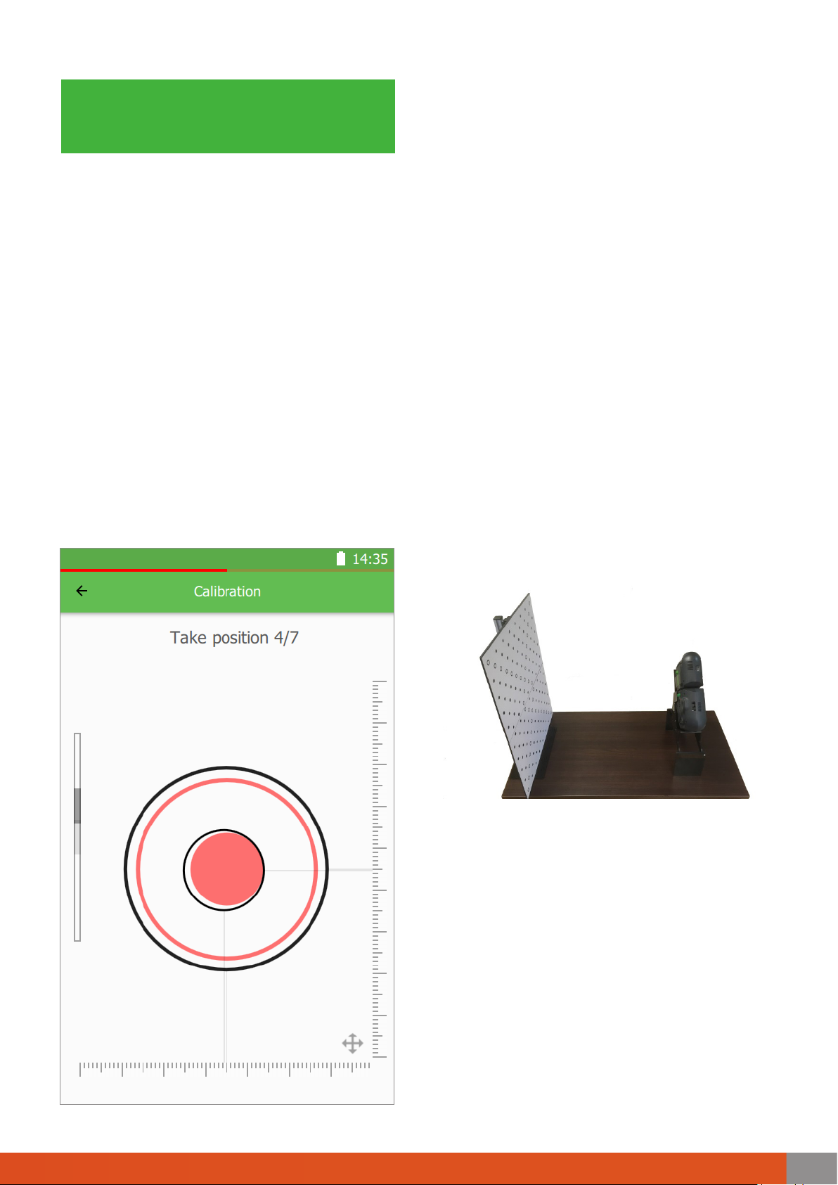
Move the scanner slowly away from the board and watch the distance
indicator for guidance as to how far to move. Once the software nishes
calibration in second position, it will prompt for the third, the fourth, etc.
There are 7 positions in total.
Once the scanner has been calibrated at all 7 positions, the software will
restart automatically and the device is ready for use.
70
70
Page 73
DRAKE
Scanner
operation
Calibration of the scanner
* To ensure the highest accuracy, do not calibrate the scanner in a well lit room (avoid direct sunlight)
and in high or low temperatures. The scanner is best calibrated in a room with temperatures between
21 and 24 degrees C (70 and 75 degrees F).
* Depending on your model, the distance from the board to the scanner will vary greatly. The scanning
board will also be different for each model. Drake MINI will use the smallest board with the smallest
circles on it and the rst position of the scanner will be approximately 18cm (7in) away from the board.
Drake MIDI will use the medium board and its starting position will be at approximately 32cm (12in)
away from the board. Drake MAXI needs the largest calibration (a combination of two medium boards)
and its starting position will be approximately 50cm (30in) away from the board.
* Calibration of Drake MAXI will also require the user to raise the scanner higher and two extra pieces of
the stand will be provided in the calibration kit. Attach the two extra “legs” to the main stand, thereby
raising the scanner off the table by 18cm (7in)
* The screen is less sensitive to the touch when the scanner is plugged in. During calibration, it is easier
and quicker to disconnect the power cable from the scanner.
71
Page 74
Drake. User manual
72
72
 Loading...