

Page 1

TIM150 1
COOK
LIKE
A
GOD
Page 2
USE AND CARE MANUAL
ICE MAKER
TIM1501
Page 3

TABLE OF CONTENTS
Ice Maker Safety··················································································· 2
Important Safeguards·································································· 3 - 5
Technical Information···········································································5
Component Locations········································································· 6
Ice Maker Installation·································································· 7 - 14
Unpacking··························································································· 7
Location Requirements··································································· 8-9
Electrical Requirements····································································10
Leveling The Ice Maker········································································11
Reversing The Door Swing························································· 11 - 12
Water Supply·············································································· 12 - 13
Drain·························································································· 13 - 14
Installation Types················································································15
Operation·····················································································16 - 20
Final Check List Before Operation ······················································16
Operating Method ······································································ 16 - 17
How The Machine Makes Ice······························································ 17
How The Machine Uses The Water······················································ 18
How The Pump Out Water Drain System Operates······················18 – 19
Normal Sounds··················································································· 20
Preparing The Ice Maker For Long Storage·········································· 20
Cleaning And Maintenance·························································· 21 - 25
Exterior Cleaning ················································································ 21
Interior Cleaning ················································································ 22
Condenser Cleaning············································································ 22
Water Distribution Tube Cleaning························································ 23
Ice-Making System Cleaning ····················································· 23 - 24
Control Panel ····················································································· 25
Ice Size Adjustment Guide ························································ 24 - 26
Major Functions·················································································· 26
Troubleshooting·········································································· 27 – 28
Warrany······················································································ 29 – 31
Page 4

ICE MAKER SAFETY
Your safety and the safety of others are very important.
We have provided many important safety messages in this manual
and on your appliance. Always read and obey all safety messages.
This is the Safety Alert Symbol. This symbol alerts you
to potential hazards that can injure or kill you and others.
All safety messages will follow the Safety Alert Symbol and
either the words DANGER, WARNING or CAUTION.
DANGER means that failure to heed this safety statement may
result in severe personal injury or death.
WARNING means that failure to heed this safety statement may
result in extensive product damage, serious personal injury or
death
CAUTION means that failure to heed this safety statement may
result in minor or moderate personal injury,or property or
equipment damage.
All safety messages will alert you to what the potential hazard is, tell you how to
reduce the chance of injury, and let you know what can happen if the instructions are
not followed.
IMPORTANT SAFETY INSTRUCTIONS WARNING:
To reduce the risk of fire, electric shock or injury when using your ice maker, follows these basic precautions:
· Plug into grounded 3-prong outlet.
· Do not remove grounding prong.
· Do not use an adapter.
· Do not use an extension cord.
· Disconnect power before cleaning
· Disconnect power before servicing.
· Replace all panels before operating.
· Use two or more people to move & install ice maker.
2
Page 5

IMPORTANT SAFEGUARDS
Before the ice maker is used, it must be properly positioned and installed as described
in this manual, so read the manual carefully. We strongly recommend that you have a
professional install your new machine. The warranty may be affected or voided by an
incorrect installation. To reduce the risk of fire, electrical shock or injury when using the
ice maker, follow basic precautions, including the following:
DANGER
• Plug into a grounded 3-prong outlet; do not remove grounding prong, do not use an adapter, and do
not use an extension cord.
• It is recommended that a separate circuit, serving only your ice maker, be provided. Use receptacles
that cannot be turned off by a switch or pull chain.
• Do not connect or disconnect the electric plug when your hands are wet.
• Never unplug the ice maker by pulling on the power cord. Always grip the plug firmly and pull straight
out from the outlet.
• Never clean ice maker parts with flammable fluids. Do not store or use gasoline or other flammable
vapors and liquids in the vicinity of this or any other appliances. The fumes can create a fire hazard or
explosion.
• Before proceeding with cleaning and maintenance operations, make sure the power line of the unit is
disconnected and the water line is shut off.
• Before operating, pull all panels back into place.
• Never allow children to operate, play with or crawl inside the ice maker.
• Do not touch the evaporator with your hand when the machine is operating.
• Unplug the ice maker or disconnect power before cleaning or servicing. Failure to do so can result in
electrical shock or death.
• Do not attempt to repair or replace any part of your ice maker unless it is specifically recommended in
this manual. All other servicing should be referred to a qualified technician.
WARNING
• Use two or more people to move and install the ice maker. Failure to do so can result in back or other
injury.
• To ensure proper ventilation for your ice maker, the front of the unit must be completely unobstructed.
Choose a well-ventilated area with temperatures above 45°F (7°C) and below 110°F (43°C).
• The ice maker should not be located next to ovens, grills or other sources of high heat.
• The ice maker must be installed with all electrical and water connections in accordance with state and
local codes. A standard electrical supply (115 V AC, 60 Hz, 15 A), properly grounded in accordance with
the National Electrical Code and local codes and ordinances, is required.
• Do not kink or pinch the power supply cord between the ice maker and cabinet.
3
Page 6

IMPORTANT SAFEGUARDS
• The fuse (or circuit breaker) size should be 15 amperes.
• It is important for the ice maker to be leveled in order to work properly. Otherwise water may not flow properly
through the evaporator (ice mold). The ice production will be less than normal. You may need to make several
adjustments to level it.
• All installations must be in accordance with local plumbing code requirements.
• Make certain that hoses are not pinched, kinked or damaged during installation.
• Check for leaks after water line is connected.
• Although the unit has been tested and cleaned at the factory, due to long-term transit and storage, the first
batch of cubes must be discarded.
• Remove the packing materials and clean the ice maker before using.
• Turn on the water supply tap before switching on the ice maker. Never turn the water supply tap off when the
ice maker is working.
• Except to take ice from the unit, keep the door closed in order to reduce ice melting and to promote proper ice
formation.
• If the ice maker will not be used for a long time, before the next use it must be thoroughly cleaned. Follow
carefully any instructions provided for cleaning or use of sanitizing solution. Do not leave any solution inside the
ice maker after cleaning.
• DO NOT use solvent-based cleaning agents or abrasives on the interior. These cleaners may transmit taste to
the ice cubes, or damage or discolor the interior.
• The ice machine cleaner contains acids. Do not use or mix with any other solventbased cleaning products.
Use rubber gloves to protect hands. Carefully read the safety instructions on the container of the ice machine
cleaner.
• Do not use the apparatus other than for its intended purpose.
SAVE THESE INSTRUCTIONS
ELECTRICAL CONNECTION
Do not, under any circumstances, cut or remove the third (ground) prong from the power cord. For personal
safety, this appliance must be properly grounded. The power cord of this appliance is equipped with a 3-prong
grounding plug that mates with a standard 3-prong grounding wall outlet to minimize the possibility of
electric shock hazard from the appliance. Have the wall outlet and circuit checked by a qualified electrician
to make sure the outlet is properly grounded. When a standard 2-prong wall outlet is encountered, it is your
responsibility and obligation to have it replaced with a properly grounded 3-prong wall outlet. The ice maker
should always be plugged into its own individual electrical outlet which has a voltage rating that matches the
rating label on the appliance. This provides the best performance and also prevents overloading house wiring
circuits which could cause a fire hazard from overheated wires. Never unplug your ice maker by pulling on the
power cord. Always grip the plug firmly and pull straight out from the outlet. Repair or replace immediately all
power cords that have become frayed or otherwise damaged. Do not use a cord that shows cracks or abrasion
damage along its length or at either end. When moving the ice maker, be careful not to damage the power cord.
EXTENSION CORD
Because of potential safety hazards under certain conditions, it is strongly
recommended that you do not use an extension cord with this ice maker.
4
Page 7

TECHNICAL INFORMATION
MODEL: TIM1501
ELECTRICAL POWER: 115VAC ~ 60HZ
POWER CONSUMPTION: 9.71 KWH/100 LBS OF ICE
ICEMAKING /HARVEST RATED CURRENT: 3.0A/4.0A
REFRIGERANT: R134A, 3.88 OZ
HIGH/LOW SIDE PRESSURE: 350 PSIG/130 PSIG
WIDTH X DEPTH X HEIGHT: 14.6" X 23.6" X 32.6"
UNIT WEIGHT: 84 LBS
MAXIMUM ICE STORAGE: 25 LBS
ICEMAKING CAPACITY: 50 LBS/DAY*
ICE SHAPE: CUBE
ICE CUBE DIMENSIONS: 7/8” X 7/8” X 7/8”
The technical data and performance index listed above
should be used for reference only. They are subject to
change.
The actual quantity of ice produced per day can vary with
environment and water conditions.
5
Page 8
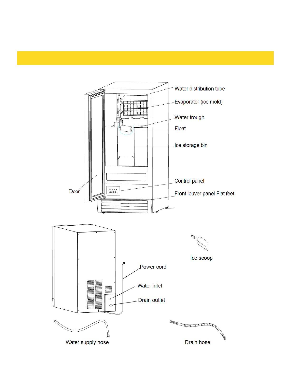
COMPONENT LOCATIONS
6
Page 9

ICE MAKER INSTALLATION
WARNING
Excessive Weight Hazard
Use two or more people to move and install ice
maker. Failure to do so can result in back or other
injury.
Remove packaging materials.
IMPORTANT: Do not remove any permanent instruction labels or the data
label on your ice maker.
Remove tape and glue from your ice maker before using.
• To remove any remaining tape or glue, rub the area briskly with your thumb.
Tape or glue residue can also be easily removed by rubbing a small amount of
liquid dish soap over the adhesive with your fingers. Wipe with warm water and
dry.
• Do not use sharp instruments, rubbing alcohol, flammable fluids, or abrasive
cleaners to remove tape or glue. These products can damage the surface of
your ice maker.
CLEANING BEFORE USE
After you remove all of the packaging materials, clean the inside of your ice
maker before using it. See the "Interior cleaning" in the Cleaning and Maintenance section.
7
Page 10
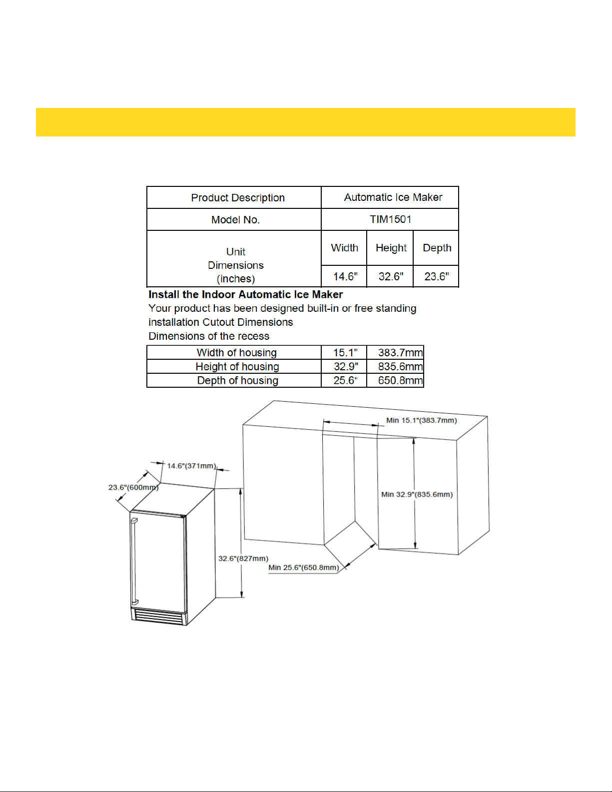
LOCATION REQUIREMENTS
8
When installing the ice maker under a counter, follow the recommended
spacing dimensions shown. Allow at least 2" (50.8 mm) of clearance at rear,
and ¼" (6.35mm)at sides for proper air circulation. The installation should
allow the ice maker to be pulled forward for servicing if necessary.
Page 11

LOCATION REQUIREMENTS
• This ice maker should be properly installed by qualified personnel.
• To ensure proper ventilation for your ice maker, the front of the unit must be completel unobstructed.
• Choose a well ventilated area with temperatures above 45°F (7°C) and below 110°F (43°C).
• The unit should not be located next to ovens, grills or other high heat sources.
• Installation of the ice maker requires a cold water supply inlet of ¼-in. (6.35mm) soft copper tubing
with a shut-off valve.
• The ice maker requires a continuous water supply with a minimum pressure of 15 psig and a static
pressure not to exceed 80 psig. The temperature of the water feeding into the ice maker should be
between 41°F (5°C) and 90°F (32°C) for proper operation.
WARNING
Normal operating ambient temperature should be between 45°F (7°C) to 110°F (43°C).
Normal operating water temperature should be between 41°F (5°C) and 90°F (32°C).
Operation of the ice maker for extended periods outside of these normal temperature
ranges may affect production capacity.
• It is strongly recommended that a water filter be used. A filter, if it is of the proper type, can remove
taste and odors as well as particles. Some water is very hard, and softened water may result in white,
mushy cubes that stick together. Deionized water is not recommended.
• The ice maker must be installed with electrical and water connections in accordance with all state and
local codes.
• The unit should be located on a firm and level surface. It is important for the ice maker to be leveled in
order to work properly. If needed, you can adjust the height of the ice maker by revolving the caster. See
the Leveling the Ice Maker section.
• A standard electrical supply (115V AC only, 60Hz, 15A), properly grounded in accordance with the
National Electrical Code and local codes and ordinances, is required.
IMPORTANT: Do not kink or pinch the power supply
cord between the icemaker and wall or cabinet.
9
Page 12
LOCATION REQUIREMENTS
ELECTRICAL REQUIREMENTS
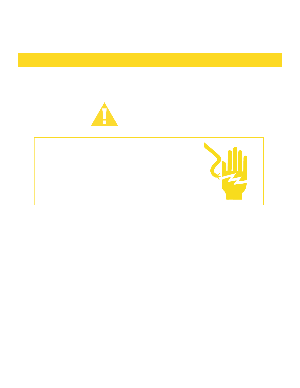
DANGER
Electrical Shock Hazard
• Plug into a grounded 3-prong outlet.
• Never remove the ground prong from the plug.
• Never use an adapter.
• Never use an extension cord.
Failure to follow these instructions can result in fire,
electrical shock or death.
Before you move your ice maker into its final location, it is
important to make sure you have the proper electrical connection:
A standard electrical supply (115V AC only, 60Hz, 15A), properly grounded in
accordance with the National Electrical Code and local codes and ordinances,
is required. The ice maker should always be plugged into its own individual
electrical outlet.
It is recommended that a separate circuit, serving only your ice maker, be
provided. Use a receptacle that cannot be turned off by a switch or pull chain.
The fuse (or circuit breaker) size should be 15 amperes.
Recommended grounding method
For your personal safety, this appliance must be grounded. This appliance is
equipped with a power supply cord having a 3-prong grounding plug. To minimize
possible shock hazard, the cord must be plugged into a mating 3-pronged and
grounding-type wall receptacle, grounded in accordance with the National
Electrical Code and local codes and ordinances. If a mating wall receptacle is
not available, it is the personal responsibility of the customer to have a properly
grounded, 3-prong wall receptacle installed by a qualified electrician.
10
Page 13
LOCATION REQUIREMENTS
LEVELING THE ICE MAKER
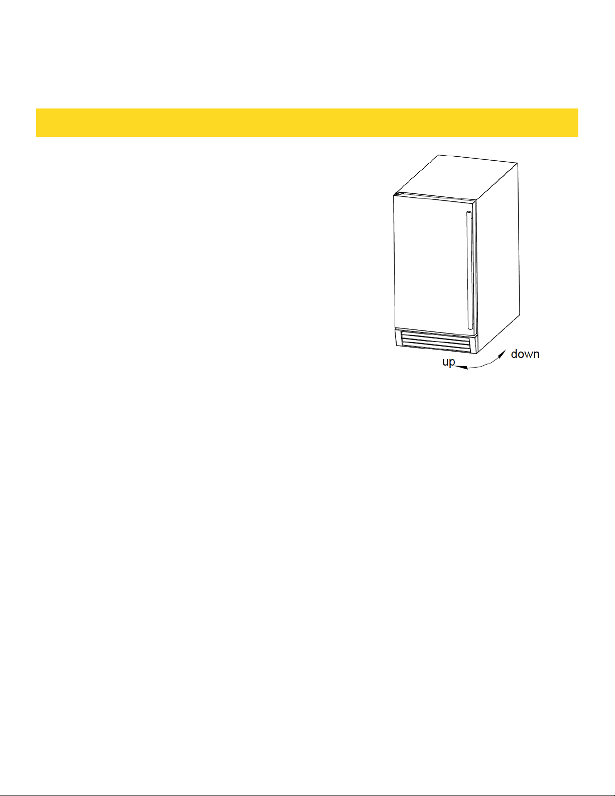
It is important for the ice maker to be leveled in
order to work properly. Otherwise water will not
flow properly through the evaporator (ice mold).
The ice production will be less than normal, and
may be noisy. The unit can be raised or lowered
by rotating the plastic sheaths around each of the
four rolling casters on the bottom of the machine.
If you find that the surface is not level, rotate the
casters until the ice maker becomes level. You
may need to make several adjustments to level it.
We recommend using a carpenter’s level to check
the machine.
1. Place a carpenter’s level on top of the unit to see if the ice maker is level from
front to back and side to side.
2. Adjust the height of the casters as follows:
Turn the leveling casters to the right to lower that side of the ice maker.
Turn the leveling casters to the left to raise that side of the ice maker.
You will find that the casters make it easy for one person to move the machine. This is useful for
cleaning and sanitizing the surface on which the ice maker is installed because it allows you to move
the unit and have easy access to the surface to be cleaned. IMPORTANT: When the ice maker is ready
to be installed in a cabinet or directly on the floor, you must adjust the feet to level the ice maker and
lock the rollers. If the floor is level, just revolve the two front feet to touch the floor. Reversing the
door swing Tools needed: flathead screwdriver, Phillips screwdriver
IMPOR TA NT: Before you begin, unplug the ice maker or disconnect power.
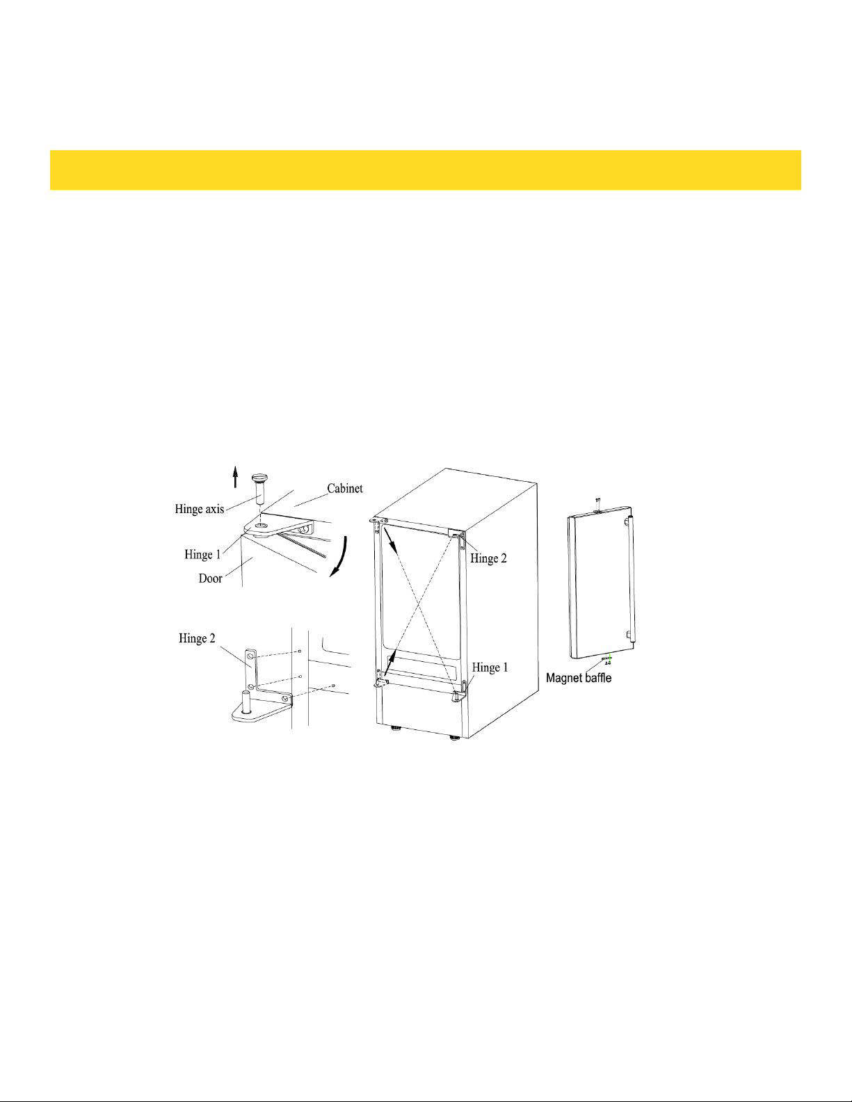
TO REMOVE DOOR FROM HINGES:
1. Using a flathead screwdriver, seperate the axis from the hinge 1. Set aside.
2. Open the door about 20°around the bottom hinge 2 axis, then lift the door off
the bottom hinge 2 and set door aside.
3. Using a flat screwdriver, remove the two plug buttons from the screw holes
on the door. Set aside.
4. Using a Phillips screwdriver, remove the magnet baffle, then place them on
the opposite side at the top of the door.
5. Push the two plug buttons into the spare screw holes.
11
Page 14
LOCATION REQUIREMENTS12LOCATION REQUIREMENTS
To replace door on hinges:
1. Using a flathead screwdriver, remove the plug buttons from the screw holes
opposite the door hinges, top and bottom. Set aside.
2. Replace the axis on the door hinge 1 and tighten it firmly. Remove the door
hinge 1 and place it on the opposite bottom side.
3. Remove the door hinge 2 and place it on the opposite top side. Separate the
axis from the hinge 2 and set it aside.
4. Keep the handle apart from the hinge side. Allign the door on the bottom
hinge 1 and replace axis on the hinge 2. Tighten it firmly.
5. Push the plug buttons into the original screw holes.
See Figure below.
Water Supply
The water supply should be ready at the point of installation. The water supply
pressure should be a minimum of 15 psig with a static pressure not more than
80 psig. (A wall outlet directly behind the ice machine will make installation
easier.)
IMPOR TA NT:
1. All installations must be in accordance with local plumbing code
requirements. Professional installation is recommended.
2. Make certain the hoses are not pinched or kinked or damaged during
installation.
3. Check for leaks after connection.
Tools required:
½-in. open-end wrench, Phillips screwdriver
Page 15
Connecting the water line:
1. Turn off main water supply. Turn on the nearest faucet long enough to clear line of
water.
2. Find a ½-in. to ¾-in. vertical cold water pipe near the installation location. The distance should be less than 6 feet. The water supply hose provided with the ice maker is
about 6 feet long.
3. A shut-off valve must be installed to the main water supply. If the water pipe
has a plain piece of copper tubing, attach a ¼” O.D. compression union to the tubing
and remove the nut.
4. Connect the nut of the water supply hose to the tap, and connect the other end with
the water inlet. Tighten firmly by hand, then one-half turn with wrench.
5. Turn on main water supply and tap. Check for water supply connection leaks. Tighten every connection (including connection at the water inlet).
IMPOR TA NT: When you connect the water supply hose and the drain hose, pay
attention to the indications of “Water inlet” and “Drain outlet” on the machine.
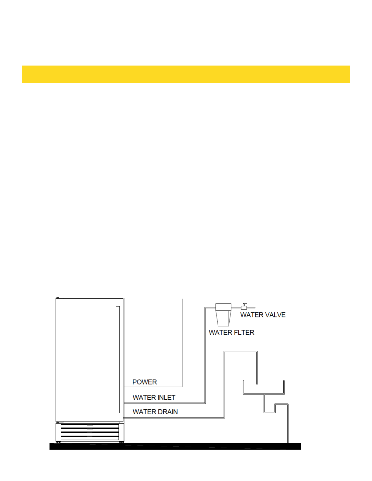
Drain
You must connect the drain line before using the ice maker. Follow the steps outlined
below. There are two types of ice machine modes, one that drains by gravity and one
that has an internal drain pump. This unit can pump out water up to a rise of 1.5m (59”)
or over a horizontal length of 1.5m (59”).
13
Page 16
LOCATION REQUIREMENTS
Connecting the drain line:
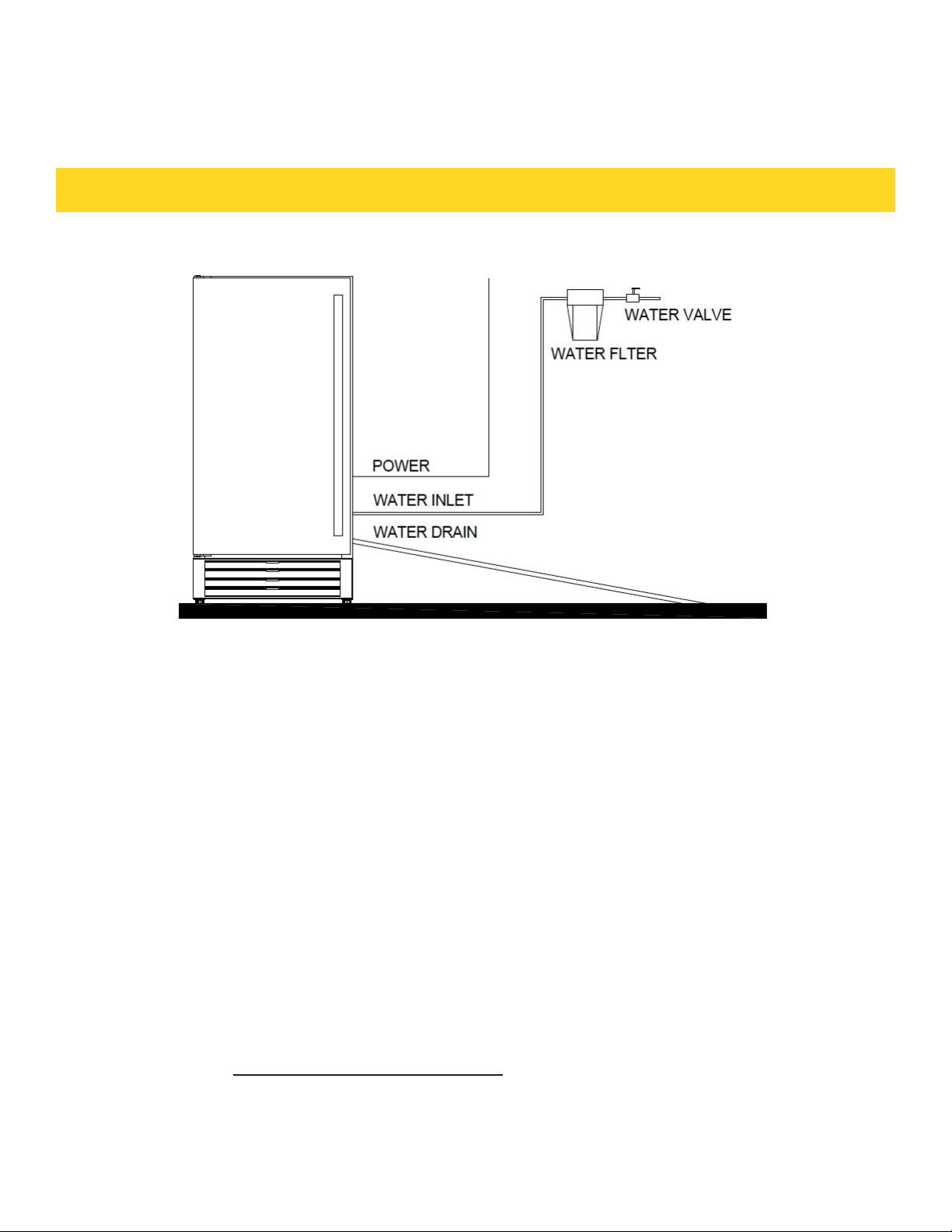
NOTE: If there is a drain line near the ice maker, the best choice is to drain
water to the drain line through the drain water hose provided with ice maker.
1. Locate the floor drain near the ice maker. The distance should be less than 5 feet
since the length of the long drain water hose provided with the ice maker is about 5
feet.
2. Find the drain outlet on the back of ice maker. Connect the drain outlet to the water
draining hose, and insert the other end of the hose into the drain line.
3. All horizontal runs of drain lines must have a fall of ¼” per foot. An air gap will
likely be required between the ice maker drain tube and the drain/waste receptacle. A
standpipe with a trap below it would be acceptable for the drain/waste receptacle. A
floor drain is also acceptable. If this is not possible, the use of a condensate pump is
recommended.
4. Pour 1 gallon of water into the ice storage bin to check for leaks in the drainage
system. Tighten any connections that leak.
IMPORTANT: This ice maker is not a freezer. Infrequent drainage will
cause a high rate of melting in the ice storage bin.
14
Page 17

LOCATION REQUIREMENTS
Installation Types
This ice maker has been designed for Mobile (free-standing) installation.
However, it can also be Enclosed (as under a cabinet) or Built-in (sealed to the
floor). In any case, there must be adequate air space around the unit for
ventilation.
Mobile installation:
A mobile installation will allow you to install the ice maker free-standing in any
place you desire provided you have access to a water supply. You must follow the
stated instructions for
a. Electrical requirements
b. Water supply
c. Leveling the ice maker.
Enclosed Installation:
An enclosed installation will allow you to install the ice maker under a cabinet
or in a kitchen cabinet provided the required clearance space around the ice
maker is respected. This installation has the same requirements as a mobile
installation.
Built-in installation:
If this method of installation is chosen, it will still be necessary to allow
adequate ventilation space around the unit. The following additional items must
be observed.
1. Place ice maker in front of installation location. Remove the feet and place the
unit flat on the floor or on a platform depending on your installation
requirements.
2. The water supply line must be plumbed before connecting to the ice maker.
3. Turn on main water supply and tap. Check for water supply connection leaks.
Tighten every connection (including connection at the water inlet).
4. If the electrical outlet for the ice maker is behind the cabinet, plug in the ice
maker.
5. Push the ice maker into position.
6. Seal all around the cabinet to the floor with an approved caulking compound.
IMPORTANT: Be sure the drain hose is connected and fed into the drain
line before the ice maker is moved into its final position.
15
Page 18
OPERATION
Final Check List before Operation
1. Have all packing materials and tape been removed from the interior and exterior of the ice maker?
2. Did you clean the ice storage bin?
3. Have the installation instructions been followed, including connecting the machine to water and
electricity?
. Has the machine been leveled?
5. Is the ice maker in a site where the ambient temperature is between 45°F (7°C) and 110°F (43°C) and
the water temperature between 41°F (5°C) and 90°F (32°C) all year- round?
6. Has the water supply pressure been checked to ensure a minimum of 15 psig with a static pressure
not to exceed 80 psig?
7. Is there a clearance of at least 4” (102mm) at the rear, and 1” (25 mm) at top and sides for proper air
circulation?
8. Has the power supply voltage been checked or tested against the nameplate rating?And has proper
grounding been installed in the ice maker?
9. Is the ice maker plugged in?
10. Have you turned on the main water supply and tap?
11. Have you checked for leaks at all water supply connections?
OPERATING METHOD
1. Turn on the water tap, let the water trough fill, then press the ON/OFF butto
on the front panel. The ice maker will start working automatically.
2. After 3 minutes, the machine will automatically go to the ice-making stage,
and the sound of water flowing will be heard.
3. When the batch of ice has been fully formed, ice will automatically be
harvested to the ice storage bin.
16
Page 19

OPERATION
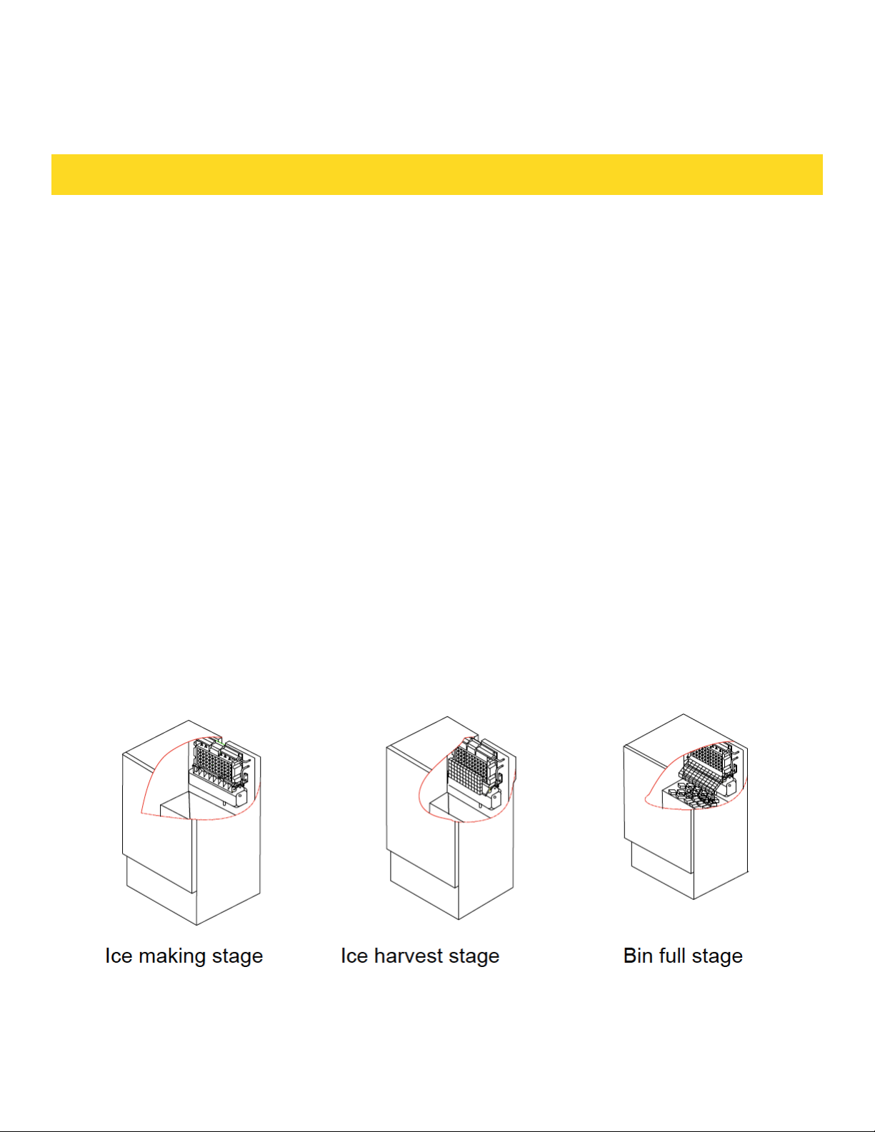
4. When the ice storage bin is full, the sheet of cubes will not fall completely and
will hold the bin-full probe open. The machine stops making ice automatically.
5. The unit will start making ice again after the ice cubes are removed. Then the
bin-full probe swings back to operating position.
6. Bin light (If present): The bin light will be controlled by magnetic reed
switch that has been installed in the inner of the door. It can be Turn On or Off
automatically with the door opening or closing.
7. Pump Water Drain system (If use): as soon as the ice melt water or other
surplus overflow water into the water reservoir reaches the maximum level,
the water lever switch close and transmit a low voltage current to PC board.
The PC board energises the water drain pump for 20 seconds pumping out
most of the water contained into the water reservoir.
IMPOR TA NT:
• Although the unit has been tested and cleaned at the factory, due to longterm
transit and storage, the first batch of cubes must be discarded.
• Never turn the water supply tap off when the ice maker is working.
• Never touch evaporator when unit is running!
• Except to take ice from the unit, keep the door closed to reduce melting and
insure proper ice formation.
How the machine makes ice
Set the ON/OFF button to the ON position. The machine will automatically go to
the ice making stage.
There are two distinct cycles: ice freeze and harvest.
The freeze cycle happens when water flows to the evaporator surface. The
harvest cycle is when the ice is released and water enters the machine. A
complete cycle takes about 20 minutes, but it depends on temperature and
operating conditions.
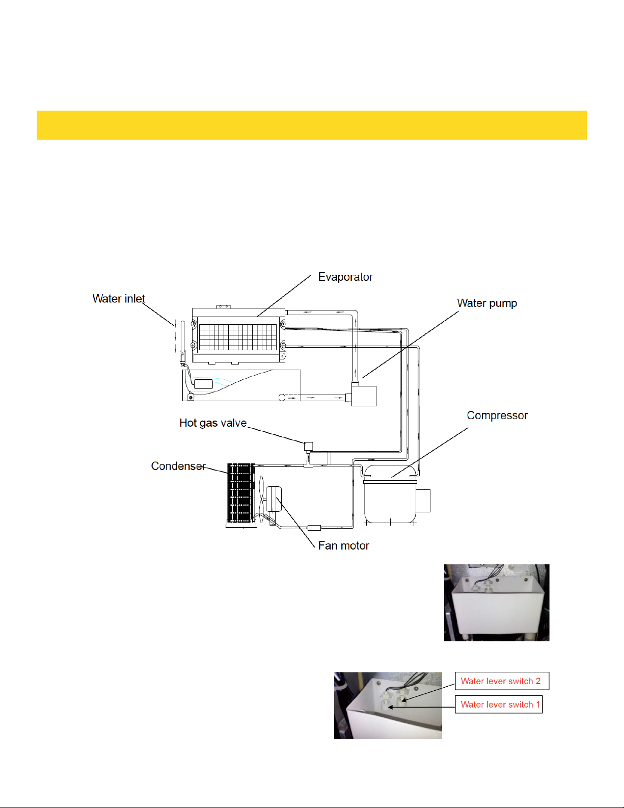
Freeze: During the freeze cycle the compressor is pumping refrigerant, the fan
motor is blowing air, and the water pump is circulating water. When the batch of
ice has been fully formed, the ice maker stops the freeze cycle and the harvest
cycle begins.
Harvest: During the harvest cycle the compressor is still operating, but the
water pump has stopped. The hot gas valve opens, diverting hot refrigerant gas
into the evaporator. The hot refrigerant gas warms the evaporator, causing the
cubes to slide as a unit off the evaporator and into the storage bin. The
freeze cycle will restart when all the cubes have been harvested.
17
Page 20
OPERATION
How the machine uses the water
The ice maker begins with a fixed charge of water that is contained in the water
trough. As the water flows to the freezing evaporator surface, the portion of
water that does not contain mineral impurities freezes and sticks to the ice cube
molds. The water containing impurities falls back into the water trough. During
the ice making process, fresh water enters into the water trough continuously as
the water in the trough freezes continuously in the evaporator.
18
How the pump out water drain system operates
The components of the Pump Out Water Drain System are:
Water reservoir
PC Board & Water lever switch 1, 2
Water Drain Pump
OPERATION
• All water coming from the overflow, and from the
melted ice is collected inside the water reservoir.
• As soon as the water into the water reservoir
reches the maximum level, the water lever switch 1
close, transmitting a low voltage current to PC Board.
Page 21
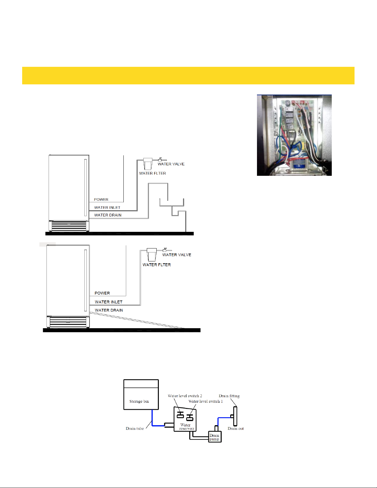
• The PC board activates the water drain pump for 20
seconds pumping out most of the water contained
into the water reservoir.
• The water can be pumped out up to 1.5m rise or to
1.5m on horizontal length.
• If the the water lever switch 2 close, transmitting a low voltage current to PC
Board. The PC board activates the buzzer alarm, informing that the drain
pump, water lever switch and drain tube may malfunction.
SCHEMATIC SYSTEM
19
Page 22

OPERATION
NORMAL SOUNDS
Your new ice maker may make sounds that are not familiar to you. Most of the
new sounds are normal. Hard surfaces like the floor and walls can make the
sounds louder than they actually are. The following list describes the sounds
that might be new to you and what may be causing them.
• Rattling noises may come from the flow of the refrigerant or the water line.
Items stored on top of the ice maker can also make noises.
• The high efficiency compressor may make a pulsating or high-pitched sound.
• Water running may make a splashing sound.
• You may hear air being forced over the condenser by the condenser fan.
• During the harvest cycle, you may hear the sound of ice cubes falling into the
ice storage bin.
PREPARING THE ICE MAKER FOR LONG STORAGE
If the ice maker will not be used for a long time, or is to be moved to another
place, it will be necessary to drain the system of water.
1. Shut off the water supply at the main water source.
2. Disconnect the water supply line from the water inlet.
3. Shut off the electric supply at the main electrical power source.
4. Take out the ice storage bin to remove any remaining ice and water. Dry the
bin.
5. Pull off the drainage tube of the water trough to drain off all water.
6. Leave the door open to allow for circulation and to prevent mold and mildew.
7. Leave water supply line and power cord disconnected until ready to reuse.
• Do not touch the power plug when your hands are wet.
• Never unplug the unit by pulling on the cord. Grasp the plug and pull out firmly.
20
IMPORTANT:
• Do not touch the power plug when your hands are wet.
• Never unplug the unit by pulling on the cord. Grasp the plug and pull out firmly.
Page 23

CLEANING AND MAINTENANCE
CAUTION
If the ice maker is left unused for a long time, before
the next use it must be thoroughly cleaned. Follow
carefully any instructions provided for cleaning or
use of sanitizing solutions. Do not leave any solution
inside the ice maker after cleaning.
Periodic cleaning and proper maintenance will ensure efficiency, top
performance, and long life. The maintenance intervals listed are based on
normal conditions. You may want to shorten the intervals if you have pets, or
there are other special considerations.
WHAT SHOULDN’T BE DONE
Never keep anything in the ice storage bin that is not ice: objects like wine and
beer bottles are not only unsanitary, but the labels may slip off and plug up the
drain.
WHAT PARTS SHOULD BE KEPT CLEAN
There are 5 things to keep clean:
1. The exterior
2. The interior
3. The condenser
4. Water distribution tube
5. The ice-making system
WARNING
Before proceeding with cleaning and maintenance
operations, make sure the power line of the unit is
disconnected and the water line is shut off.
EXTERIOR CLEANING
The door and cabinet may be cleaned with a mild detergent and warm water
solution such as 1 oz. of dishwashing liquid mixed with 2 gallons of warm water.
Do not use solvent-based or abrasive cleaners. Use a soft sponge and rinse with
clean water. Wipe with a soft clean towel to prevent water spotting. Stainless
steel can discolor when exposed to chlorine gas and moisture. Clean stainless
steel with a mild detergent and warm water solution and a damp cloth. Never
use an abrasive cleaning agent.
21
Page 24
CLEANING AND MAINTENANCE
Interior Cleaning
The ice storage bin should be sanitized occasionally. Clean the water trough
before the ice maker is used first time and reused after stopping for an
extended period of time. It is usually convenient to sanitize the trough after the
ice making system has been cleaned, and the ice storage bin is empty.
1. Disconnect the power to the unit.
2. Open the door and take out the removable ice storage bin. With a clean
cloth, wipe down the interior of unit and ice bin with a sanitizing solution
made of 1 ounce of household bleach or chlorine and 2 gallons of hot (95ºF
–115ºF) water.
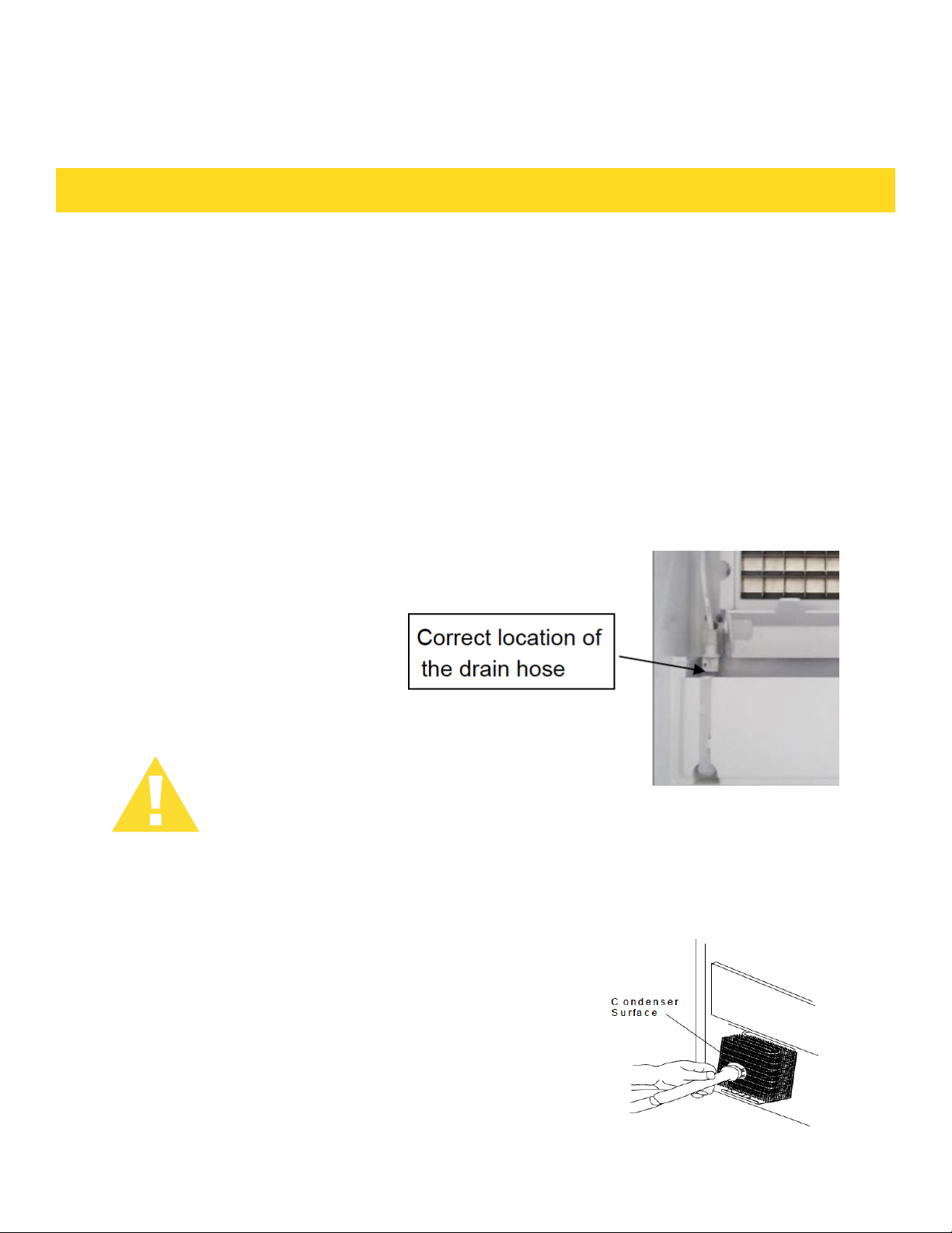
3. Pull off the drain hose of the water trough to drain off all water.
4. Rinse thoroughly with clear water.
5. After draining off all water, put back the drain hose of the water
trough into the original location.
6. Put the ice storage bin inside the unit.
7. Reconnect power to the unit.
The ice scoop should be washed regularly. Wash it just
like any other food container.
WARNING
DO NOT use solvent-based cleaning agents or abrasives on the interior. These
cleaners may transmit taste to the ice cubes and damage or discolor the interior.
Condenser Cleaning
A dirty or clogged condenser prevents proper airflow, reduces ice
making capacity, and causes higher than recommended operating
temperatures that may lead to component failure. Have the condenser cleaned at least once every six months.
1. Unplug the ice maker or disconnect power.
2. Gently pull off the lower front louver.
3. Remove dirt and lint from the condenser and the unit compartment with the brush attachment of a vacuum cleaner.
4. Reassemble the lower front louver.
5. Plug in the ice maker or reconnectpower.
22
Page 25

CLEANING AND MAINTENANCE
Water distribution tube cleaning
When you find the ice cubes are incompletely formed or the output is low,
the water distribution tube may be blocked. Turn off the power button, gently
take out the water distribution tube, locate the holes in the distribution tube
and use a pointed object such as a toothpick to dredge the holes. Then put the
water distribution tube back to its original position. If the tube is badly blocked,
clean it as follows:
1. Shut off the water supply
2. Disconnect the water hose from the distribution tube.
3. Gently take out the distribution tube.
4. With a brush, clean the tube with a dilute solution of warm water and a mild
detergent such as dishwashing liquid. After removing the dirt and lint from
the surface, rinse the tube with clean water.
5. Replace the distribution tube.
6. Reconnect the water supply.
Ice-making system cleaning
Minerals that are removed from the water during the freezing cycle will
eventually
form a hard, scaly deposit in the water system. Cleaning the system regularly
helps remove the mineral scale buildup. How often to clean the system depends
upon how hard your water is or how effective your filtration may be. With hard
water of 15 to 20 grains/gal. (4 to 5 grains/ liter), you may need to clean the
system as often as once every 6 months.
1. Make sure that all the ice is off the evaporator. If ice is being formed, wait
until the cycle is completed, then press the machine’s ON/OFF switch on the
control panel.
2. Remove all ice from the storage bin.
3. Keep the ice maker connected to the water supply. Pour 8 oz. of Nickel-
Safe Ice Maker Cleaner Solution into the water trough. Then press the ON/
OFF switch and the CLEAN button, initiating the wash cycle. The machine will
run in the Automatic Clean Mode.
4. Allow 30 minutes for proper cleaning. After cleaning, press the ON/OFF
switch again. Use a drain hose on the front of the water trough to drain off the
waste water to a convenient container.
NOTE: Don’t drain off the waste water to the inside of the cabinet.
5. Repeat steps 3 and 4 (without Ice Maker Cleaning Solution) three times to
rinse the ice making system thoroughly.
• NOTE: Ice Maker Cleaner Solution in the water bin during the rinse is
not needed.
23
Page 26

CLEANING AND MAINTENANCE
WARNING
The ice machine cleaner contains acids.
DO NOT use or mix with any other solvent-based cleaner
products. Use rubber gloves to protect hands. Carefully
read the material safety instructions on the container of the
ice machine cleaner. Discard the first batch of ice produced
after cleaning.
6. Prepare a sanitizing solution made of 1 ounce of household bleach and 2
gallons of hot water (95ºF to 115ºF). Wipe the entire bin inside and outside,
covering the entire surface of the walls.
7. Fill a spray bottle with the sanitizing solution and spray all corners and edges,
making sure to cover all surfaces with the solution.
8. Allow the solution to be in contact for at least 3 minutes, then dry.
9. Repeat step 5 to rinse the ice making system one more time.
10. Press the ON/OFF button again. The machine will return to the regular ice
making mode. Discard the first batch of ice.
24
Page 27
CLEANING AND MAINTENANCE
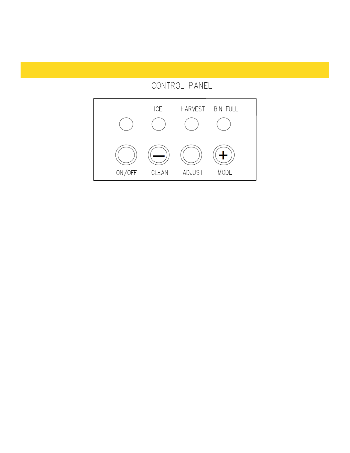
Description of LEDs and buttons:
1. Bin Full (Red) LED: Bin full indicator light
When this is lit, the ice storage bin is full of ice or there is something
blocking the bin-full probe. The unit will stop working. When ice cubes are
removed from the ice storage bin, freeing the bin-full probe, the red LED will
remain flashing for 3 minutes, then the unit will restart and return to the ice
making mode.
2. Ice Making (Green) LED: Ice making indicator light
When this is lit, the unit is working in the ice making mode controlled
by a temperature probe on the evaporator. When the green LED flashes, the
unit is working in the ice making mode controlled by a fixed timer.
3. Ice Harvest (Yellow) LED: Ice harvest indicator light
When this is lit, the unit is working in the ice harvest mode controlled by the
ice-full probe.
4. Mode button: Mainly for service. When this is pressed, the ice making mode
changes to the ice harvest mode or vice versa. The mode can be judged
from the status of the green and yellow LEDs.
5. Adjust button: Mainly for service. When it is pressed over 3 seconds, the
unit will enter the Ice Size Adjustment mode. The mode can be judged from
the status of the yellow LEDs.
Ice Size Adjustment Guide:
1. Press and hold the “Adjust” button for at least 3 seconds. The unit will enter
the Ice Size Adjustment mode. The “HARVEST” LED (yellow) will be blinking
continuously during the ice size adjustment. Release the button when the LED
blinks continuously to adjust the ice size.
25
Page 28

CLEANING AND MAINTENANCE
2. While in the Ice Size Adjustment mode, press the “Clean” (-) button or the
“Mode” (+) button for the desired ice size.
Smaller ice setting:
By pressing the “Clean” (-) button, you can decrease the size of the ice cubes.
The “ICE” LED (green) will flash as you lower the ice size and will finally be
blinking at the setting of smallest ice size.
Larger ice setting:
By pressing the “Mode” (+) button, you can increase the size of the ice cubes.
The “BIN FULL” LED (red) will flash as the larger size is set and will blink
when the setting of largest ice size has been reached.
After 10 seconds without any operation, the unit will return to the previous mode.
NOTE:
• If during the ice size adjustment mode the “BIN FULL”, “ICE” and
“HARVEST” LEDS blink all at once, this indicates that the unit is in the regular
(middle) setting of the ice size.
• When the machine is in the cleaning stage or ice full stage, the ice size
adjustment mode cannot be accessed.
MAJOR FUNCTIONS
1. The operating procedure is completely automatic.
2. When the ice storage bin is full of ice cubes, the machine stops making
ice automatically. It starts making ice again after ice cubes are
removed.
3. The different colors of the LED display indicate various work modes.
4. A sensitive probe and accurate timer enhance the performance of the
ice m aker.
5. A compressor protection system is built in.
26
Page 29
TROUBLESHOOTING
Before Calling for Service
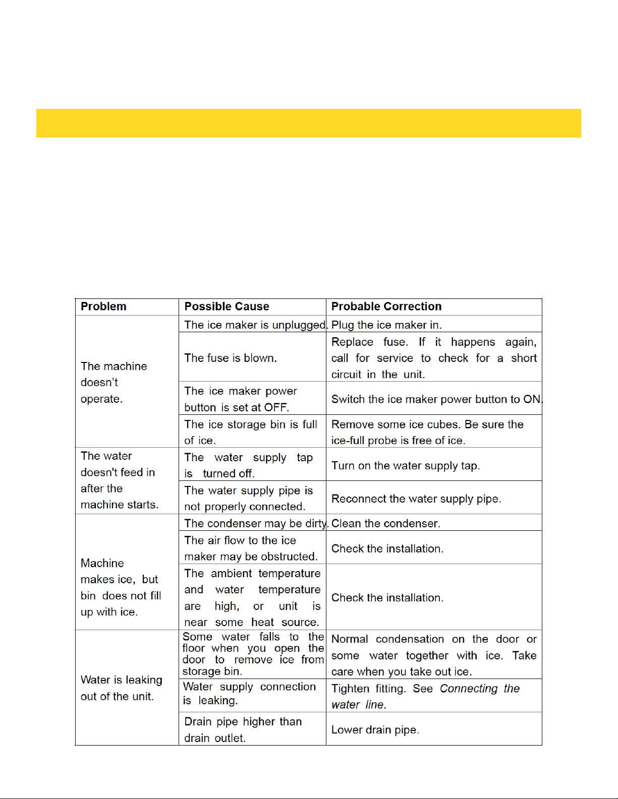
If the unit appears to be malfunctioning, read through the OPERATION
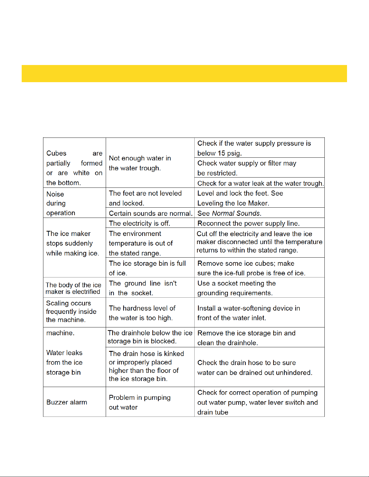
section of this manual first. If the problem persists, check the Troubleshooting
Guide on the following pages. Some of the problems mentioned in the Guide
can be solved easily without a service call.
TROUBLESHOOTING GUIDE
27
Page 30
TROUBLESHOOTING
28
Page 31

WARRANTY
WARRANTY & SERVICE
This product has been manufactured by Thor Group, 4651 E Airport Drive, California 91761
For Customer Service, please call (877) 288 - 8099
For the most up to date warranty and service policy, please refer to our website
WWW.THORKITCHEN.COM/WARRANTY-REGISTRATION
For in-warranty service requests, please visit our website atWWW.THORKITCHEN.COM/SERVICE
Please Note: You must provide proof of purchase or installation date for any
inwarranty service requests
29
Page 32
WELCOME
TO THE CLUB
You chose THOR Kitchen to enhance your culinary journey and
we’re stoked to have you in the club. Think of it as a secret
society of really savvy people, such as yourself, choosing
professional power and performance at an affordable price.
Register your product by following the steps below.
WARRANTY REGISTRATION
Scan theQR code or visit
thorkitchen.com/warranty
Input your product info
and select register
You’re done.
Let’s get cookin’.
WARRANTY NEED PARTS?
 Loading...