

Page 1
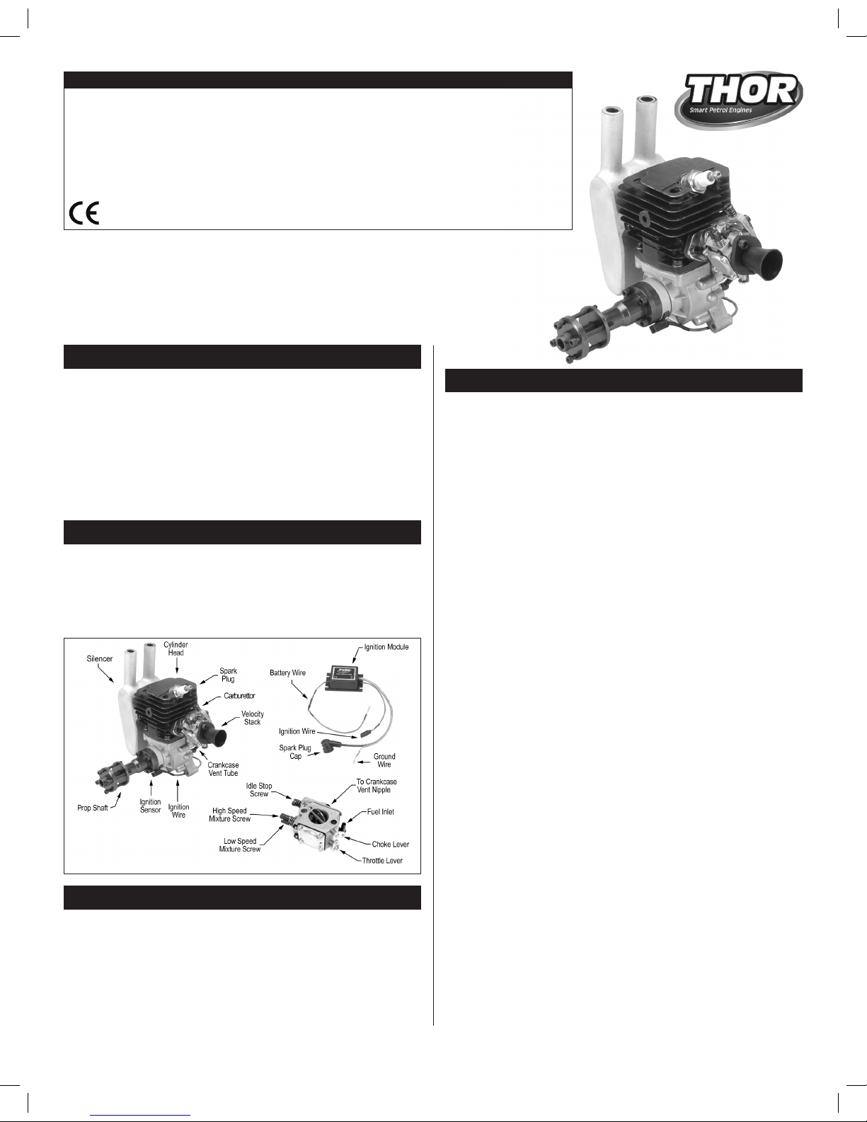
Thank you for choosing our superb new THOR 45 CDI petrol engine. The THOR
45 CDI engine is a single cylinder, two-stroke petrol engine incorporating
an easy-to-adjust Walbro carburettor with integrated pump, fully-electronic
ignition system and a high-quality, dual-ring piston for exceptional power
and ease of use. The THOR 45 CDI engine also features heavy-duty aluminum
engine mounts, a high-volume silencer and a velocity stack. We are confident
that this precision product will provide you with many hours of reliable, high-
performance flying.
This engine is intended for model aircraft use only. Do not use it in any other
application.
This is an air-cooled engine, so you must provide adequate cooling for the
engine and the exhaust.
Use a good-quality propeller and spinner. Always make sure to balance both
the propeller and the spinner before mounting them onto the engine.
When drilling the propeller to fit the propeller bolt, make sure that the hole
is centered and take care not to weaken the propeller by drilling holes in the
strengthening webs when you drill the four radial bolt holes.
Make sure that the propeller bolts are tightened securely and check them
for proper tightness regularly.
The ignition module should be mounted to avoid vibration, heat and fuel
oil.
You must use a kill switch (not supplied) between the ignition battery and
the ignition module.
To avoid radio "noise" caused by metal-to-metal contact, connect the throttle
cable to the throttle arm using a heavy-duty nylon clevis.
To prevent unwanted RF interference, always keep any part of the radio control system (servos, receiver, flight battery, aerial, etc) 300mm (12") away from
the ignition module. Perform a range check with the engine running. We find
the use of PCM receivers to be more reliable and therefore recommended.
Always use a Chicken Stick or wear a heavy-duty leather glove to start the
engine.
Ensure that the spark plug is in good condition, is set to the correct gap (see
specifications above), and is tightened completely.
Ensure that the spark plug cap is firmly seated on the spark plug.
Do not wear loose clothing or allow anything to be drawn into the spinning
propeller while the engine is running.
If you need to carry your model while the engine is running, be conscious of
the spinning propeller. Keep the airplane pointed away from you and others
at all times.
Do not attempt to make carburettor adjustments while the engine is
running. Always shut down the engine first.
Keep all spectators at a safe distance while the engine is running.
Never stand directly in the arc of the spinning propeller.
Make sure your aircraft is firmly secured when you start the engine. It's
advised to have a helper hold the aircraft while you start and run up the
engine.
INTRODUCTION
BECOMING FAMILIAR WITH YOUR ENGINE
We strongly recommend reading through these operating instructions in
their entirety to familiarise yourself with the features and operation of your
new engine. Whether this is your first petrol engine or if you've run them in
the past, following these operating instructions closely will reward you with
a great running and trouble-free engine.
1
WARNINGS AND PRECAUTIONS, CONTINUED
Displacement ..........................45cc (2.745in3)
Bore: ...................................... 43mm (1.693")
Stroke: ................................... 31mm (1.221")
Practical RPM: ........................1,600 - 7,800
Maximum Power Output: ........ 4.2hp
Weight w/Muffler: ....................1650g (58.2oz)
Ignition Type: ...................... DC-CDI (Fully Electronic)
Ignition Power Source: .......6V DC (5 Cell NiCd/NiMh)
Spark Plug Gap: ................. 0.7mm (0.028")
Static Ignition Timing: ......... 12°-14° BTDC
Fuel Required: .................... 89-91 Unleaded w/2-St. Oil
Fuel/Oil Ratio: ..................... 25:1 to 40:1
Oil Type: .............................. 2 Stroke Synthetic
(Castrol TTS or similar)
This engine is not a toy. It is a precision-built machine whose power is capable
of causing serious injury to yourself and others if abused or misused, or
if you fail to observe proper safety precautions while using it.
Mount the engine securely in the aircraft or on a suitable engine test stand
to run the engine. Follow the mounting instructions in your kit's instruction
manual for individual mounting recommendations. Do not clamp the engine
in a vice to test-run it.
WARNINGS AND PRECAUTIONS
Due to running manufacturing
changes and improvements, your
engine may differ slightly from
that shown.
THOR 45 CDI PETROL ENGINE
OPERATING INSTRUCTIONS
THOR 45 CDI ENGINE SPECIFICATIONS
Page 2
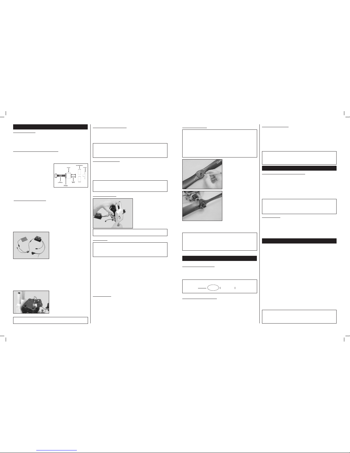
The silence r is moun ted to th e
engine using the two steel socketcap screws, two spring washers,
two square re taini ng nuts an d
the gasket provided. Also ma ke
sure to tighten the screws firmly.
Notice that the nuts slide behind
the muffler mounting flange on the
engine.
IMPORTANT The standard silencer can be mounted only in the direction
shown. Optional replacement silencers are available.
3
STARTING PROCEDURE
Propeller Installation
WARNING Before installing the propeller it must be properly balanced.
Balance the propeller AFTER drilling both the centre hole and the four radial
holes. Running yo ur engine us ing an out-o f-balanc e propelle r can lead
to excessive vibration, which will result in excessive stress and wear on
both the engine and the airframe. Balance the propeller usin g the method
recom mended by the propell er ma nufactu rer. Severa l pro ducts are
avail able to properly balance propellers. Ask your local retailer for more
information about these items.
The di amete r of the pro pelle r
ret aining bol t is 8mm (0.315 ").
Using a dril l b it or a propel ler
reamer , enla rge the hole in the
propeller hub to fit the retaining
bolt. Slide the p ropeller retaining
bolt and the propeller washer onto
the propeller, then use the holes in
the propeller washer to mark the
locations of the four ra dial retain-
ing bolts onto the propeller.
Remove the retaining nut and pro-
peller washer, then drill four 4mm
(5/32") diameter holes through the
prope ller. If you have one , w e
suggest using a drill press to drill
these holes.
Install your propeller loose to make
it easy to line up and thread the four radial retaining bolts into place. Fina lly,
tighte n the c entre bo lt, then tighte n the f our radi al bolts in a criss-cross
pattern.
WARNING If you are installing a spinner onto your engine, the cone of
the spinner must not rub against the propeller. Allowing the spinner cone
to rub against th e propeller could lead to propeller damage and eventual
propeller fai lure. We also strongly suggest balancing your spinner before
installing it.
We suggest using only high-quality propellers made from wood, carbon-fibre
or glass-reinforced nylo n. Don't forget to balance the propeller as described
in the previous section.
PROPELLER SIzE RECOMMENDATIONS FOR THOR 45 CDI ENGINE
Propeller Recommendation
PROPELLER, FUEL AND SPARK PLUG
Use for
Running-In
20 x 8 22 x 820 x 10
Spark Plug Recommendation
The spark plug included with your engine is designed specifically for your
engine. Factory replacements are available and can be purchased directly
from your THOR engine dealer. When pur chasing a new spark plug we
suggest double-checking the gap using a gap gauge tool found at auto-parts
shops. The spark plug gap should be set to a gap of 0.7mm (.028") with
the spark plug cold. Th e spar k plug should be replaced when signs of
electrode wear are present.
Fuel Recommendation
The fuel you u se sho uld b e high -octane (89 or 91) premi um un leaded
petrol mixed with a high-quality synthetic two-stroke engine oil (Castrol TTS
recommended) at a ratio of 25:1 for the first 2-3 hours of run-time and a
ratio of 40:1 thereafter. We don't suggest using more oil than recommended
since damage to the p iston rings and pi ston c ould r esult. We a lso do n't
sugg est adding per formance-boo sting additives to your fuel. Doing so
will void your engine's warranty.
IMPORTANT Always mix your fuel in a clean container and filter it before
filling your fuel tank. We also strongly recommend using an in-line fuel filter
between your fuel tank and the carburettor. 'Felt' type fuel tank clunks are
also recommended.
High and Low Speed Mixture Screws
The high speed mixture screw is used to meter the air/fuel mixture at full
throttle. The low speed mixture screw regulates the air/fuel mixture at idle
and during transition from idle to full throttle. Both mixture screws operate
the same. Turn the mixture screw(s) clockwise to lean the mixture or turn the
mixture screw(s) counterclockwise to richen the mixture. Both mixture screws
are preset from the factory for initial starting. They will need final adjusting to
suit your atmospheric conditions, fuel, temperature, altitude, etc.
If your high and low speed mixture screws get too far out of adjustment,
reset them to the factory settings:
High Speed Mixture Screw: 1.5 turns out from fully closed.
Low Speed Mixture Screw: 1.5 turns out from fully closed.
CARBURETTOR ADJUSTMENT SCREWS
Idle Stop Screw
Althoug h we suggest usin g your tran smitter's idle trim lever to set t he
idle speed of the engine, you can also set the idle speed of the engine
using the idle adjustm ent s crew o n the carb urettor. Turning the screw
clockwise will increase the idle speed and turning the screw counterclockwise
will decrease the idle speed. The screw is set at the factory and should not
require adjustment.
The starting procedure for the THOR 45 CDI engine is actually quite simple.
For ease of starting we recommend using a high-torque electric starter with a
good quality 12V car battery. The engine can be started by hand, but only using
a chicken stick. We strongly discourage it, but if you must use your hand to start
the engine, you MUST wear a heavy-duty leather glove.
Verify that the ignition kill switch is in the "off" position and fill the fuel tank
with fresh, filtered fuel. Before filling the fuel tank, gently shake your fuel
container to remix the oil and petrol mixture.
Open the throttle completely, close the choke and rot ate the propeller
by hand counterclockwise through the compression stroke 4-6 times to prime the
engine. Open the choke. The first start may require a lot more rotations to prime
the carburettor for the first time.
Set the throttle to idle, then pull the propeller slowly through the compression
stroke once, leaving the propeller just below the top of the next compression
stroke.
Turn on the kill switch and start the engine using an electric starter or by
hand. If starting by hand, the engine should start within about 5 or 6 flips.
Once the engine starts, maintain a fast idle for no less than 1 minute to allow
the engine to warm up.
IMPORTANT Make sure you never start the engine with the carburettor
set any higher than the idle setting. Trying to start the engine at a higher
throttle setting can result in the engine backfiring or lurching forward. This
can quickly lead to damage to the engine and/or personal injury.
2
The THOR 45 CDI engine features direct-to-firewall mounting. The firewall in
your model should be aircraft grade 5-ply plywood no less than 9.5mm (3/8")
thick and the firewall should be reinforced to meet the torque and weight of
the engine. Use only high-quality 5mm
steel cap screws and related hardware
to mount the engine.
Should you decide to mount the engine
using rubber shock mounts, we strongly
sug gest us ing hig h-qu alit y m ount s
designed specifically for single cylinder
petrol engines. Using the wrong type of rubber shock mounts can lead to an
erratic running engine and possible engine damage.
ENGINE INSTALLATION
Engine Orientation
The THOR 45 CDI engine features a high-quality Walbro carburettor with
an inte grated fuel pump, so the engi ne can be orientated in any position
on the firewall without the fuel-draw problems associated with non-pumped
engines.
Engine Bolts & Firewall Requirements
The ignition modu le sh ould be m ounted near the engine, as far away
from your airborne radio equipment as p ossible. It sho uld be protecte d
from excessive heat, vibration and fuel oil. We recommend wrapping it in
foam rubber (like used for your receiver), then securing it into place using
double-sided tape or silicone glue.
You will need to install a kill switch (sold separately) between the ignition module
and your ignition battery. The kill switch should be mounted in a convenient
location on the outside of the model far enough away from the engine so as not
to pose a risk when using the switch.
For models over 7kg in the U.K. this
switch should be operated by the radio
so that the engine can be switched off
by the ‘failsafe’ system.
To power the ignition system you will
need to use a separate battery pack
that is 6.0V (5 cells) and a capacity of
1100mAH to 3000mAH. NiCd or NiMH
cells can be used. The battery should be wired to the kill switch (making sure
that the polarity is correct) and mounted inside your model, at least 300mm
(12") away from the ignition module. For convenience, a charge jack can be
wired along with the kill switch so that you can charge the battery without
having to remove it from the model. A standard on/off switch (or connectors)
with a charge jack works well.
To ground the ignition syste m, slide the ‘ground’ cable harness over th e
threaded end of the spark plug, then install the spark plug into the engine
(make sure that it's tightened securely). Push the rubber cap over the end of
the spark plug until it snaps firmly down
into place.
Next, plug the ignition wire from the
engine into the matching ignition wire
from the ignition module.
IMPORTANT The ignition sensor is pre-installed at the factory in the
correct position. Do not attempt to adjust the sensor mount.
Ignition System Installation
Throttle Pushrod Installation
To reduce the chance of radio "noise", we don't recommend using a metal
pushrod wire. We suggest using a nylon tube-in-sleeve style pushrod. Make
sure to attach the pu shrod to the thro ttle lever using a heavy-duty nylon
clevis. You want to avoid any metal-to-metal contact.
IMPORTANT Do not remove the throttle lever spring. This spring helps
keep the carburetor butterfly aligned properly. Merely release the ends of
the spring so that it no longer holds the butterfly closed. This will ease the
strain on your throttle servo.
Choke Rod Installation
If the carburettor is accessible, we suggest leaving the choke open, and using
your finger to cover the carburettor opening to choke the engine. If this is not
possible, you can attach a choke rod to the choke lever. As with the throttle
pushrod, make sure to use a heavy-duty nylon clevis to secure the choke rod
to the choke lever.
IMPORTAN T If the choke ro d is more than 75mm (3") long, we sug gest supporting the ou ter end of the choke rod to pr event vibratio n from
damaging the choke mechanism.
Silencer Installation
IMPORTANT Because this is a petrol engine, your fuel system (fuel tank
and stopper assembly, fuel lines, filters, fuel valves, etc) must be designed
for use with petrol. Do not use accessories designed for use with glow fuel.
Do not use silicone-based materials.
The THOR 45 CDI engine uses a Walbro carburet tor wit h an integrated
fuel pump. For this reason, the location of the fuel tank is not critical. The
pump will draw fuel in to the carburettor regardless of the location of the
fuel tank. For best aircraft performance we suggest installing the fuel tank
over the models C/G so that no trim changes will be necessary as the fuel
quantity lowers in the tank.
We r ecommend using a fuel tank n o smaller than 570ml (20 oz) . Make
sure that the fuel tank is vented outside of the model during use. Exhaust
pressuri sation is no t requ ired a nd wou ld act ually be det rimental to the
running.
Fuel System
Proper cooling is vital to e nsure prope r running and longevity from your
engine. It is imperative that your model be constructed to provide adequate
airflow over the engine and muffler. This means having appropriately sized
air-intake and air-exit areas. For proper cooling the air-exit area should be 4
times the size of the air-intak e area. For exa mple, 65cm2 (10 in2) of airintake area will require 650cm2 (40 in2) of air-exit area. This formula ensures
that your engine will not overheat due to inadequate air flow.
Engine Cooling
Page 3
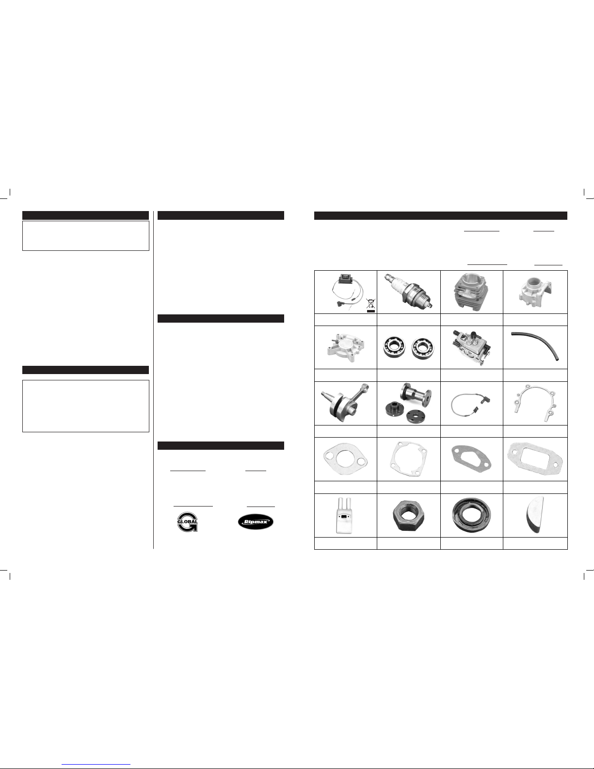
THOR 45 PETROL ENGINE REPLACEMENT PARTS LIST
THR45-0110
Crankcase - Front
THR45-0170
Bearings - Crankshaft
THR45-0360
Carburettor Assembly
THR45-0370
Crankcase Pressure Tube
THR45-0160
Crankshaft w/Connecting Rod
THR45-0190
Prop Mount Assembly
THR45-0310
Sensor
THR45-0150
Crankcase Gasket
THR45-0340
Carburettor Gasket - Outer (2)
THR45-0040
Cylinder Base Gasket
THR45-0330
Carburettor Gasket - Inner
THR45-0410
Silencer Gasket
THR45-0120
Crankcase - Rear
THR45-0010
CDI Ignition Module
THR45-0020
Spark Plug
THR45-0030
Cylinder
Global Services
18480 Bandilier Circle
Fountain Valley, CA 92708
Phone: (714) 963-0329
Fax: (714) 964-6236
Email: [email protected]
Ripmax Ltd.
241 Green Street,
Enfield, U.K. EN3 7SJ
Phone: (0) 20 8282-7500
Fax: (0) 20 8282-7501
Email: [email protected]
In North America:
In Europe:
TO ORDER RE PLACEMENT PARTS, PLE ASE VIS IT YOUR LOCAL THOR
PETROL ENGINE DEALER FIRST. I F YOUR LOCAL DEALER DOES NOT
STOCK THOR PET ROL ENGINE PARTS, PLEASE C ONTACT THE LOCAL
THOR PETROL ENGINE DISTRIBUTOR SHOWN HERE.
THR45-0380
Flat Standard Silencer
THR45-0210
Crankshaft Retaining Nut
THR45-0180
Crankshaft Seal
THR45-0200
Woodruff Key
Continued on Back Page
4
IMPORTANT During the running-in procedure, DO NOT run the engine
at full power for more than 10 seconds. This will ensure that the engine
does not overheat. Since you're running the engine on a test stand there
is much less cooling air flowing over the engine than if the engine was in a
model that was flying.
The running-in process allows the engine parts to perfectly fit each other and
properly prote ct each part fro m premature wear. We suggest that you start
the running-in process with the engine on a test stand for approximately 1
hour, then mount the engine into your model and fly. Running-in in the engine
is a simple process. Follow the suggestions below:
Use a fuel/oil mixture ration of 25:1 for the running-in process. The extra oil will
aid in the running-in process and help prevent overheating and premature wear.
This fuel mixture ratio should be used for the first 2-3 hours of runtime.
Use a smaller diameter propeller than you would normally use. We recommend
a 20 x 8. The smaller propeller will not load the engine as much.
Start the engine and allow the engine to idle for no less than 1 minute to
allow it to adquately warm up. After 1 minute slowly advance the throttle to
approximately half throttle and allow the engine run for 5 minutes, then bring
the engine back down to idle.
Continue to run the engine at varying throttle settings for approximately 1
hour, being conscious not to run the engine at full throttle for more than 10
seconds. Allow the engine a cool down period every 15 minutes or so. After 1
hour, the engine can be installed into your model and flown.
RUNNING-IN PROCEDURE
RUNNING THE ENGINE
IMPORTANT Be aware that when the engine is new, it wil not produce
the rpm and power that a well used engine will. Expect rpm's to increase as
you run the engine more and more. The engine will require about 12 - 20
hours of run-time before it will produce its full power potential.
VERY IMPORTANT Be careful never to lean the engine out too much.
Remember that the lubricants for your engine are suspended in the fuel. If
you lean out the fuel mixture too much you will also be lowering the amount
of lubricant entering your engine. Less lubricant means more chance of your
engine overheating and possible engine failure.
W hen you make adjustments to the carburettor, you m ust shut off the
engine using the kill switch.
You should use a 25:1 fuel/oil mixture ratio for the first 2-3 hours of runtime.
After that, you can use a 40:1 fuel/oil mixture ratio.
Mount the engine into your model. Start the engine and allow it to idle for
about 1 minute to allow it to adquately warm up. After 1 minute, advance the
throttle to full. Using a tachometer, adjust the high speed mixture screw for
full power, then turn the high speed mixture screw counterclockwise about 5°
to richen the mixture slightly. This is the setting at which you should fly the
model.
B ring the throttle down to idle and allow th e engine to idle for 30 seconds.
After 30 seconds, advance the throttle to full. The engine should transition
from idle to full power smoothly and quickly. If the engine quits suddenly, the
low sp eed mix ture is too lea n. Turn the lo w speed mixture screw counterclockwise 5° to richen the idle mixture. If the engine splutters and quits, the
low speed mixture is too rich. Turn the low speed mixture screw 5° clockwise
to lean the mixture. Start the engine and check the transition again. If it's still
not correc t, repeat this procedure until you're satisfied with the transition.
Unlike a glow engine, these needles require very little movement to change
the mixture.
Problem: The engine is flooded.
Solution : Remov e the spark plug and turn the e ngine u pside down t o
drain any excess fuel from th e engine. Dry off spark plug electrode an d
reinstall the spark plug.
Problem: The engine starts after being choked, but stops shortly after.
Solution: The low speed mixture is probably too lean. Readjust the low speed
mixture screw to 1.5 turns out from fully closed and readjust from there. This
problem can also be caused by a dirty carburettor or faulty ignition.
Problem: The engine runs rough and vibrates excessively
Solution: Balanc e the propelle r and spinner, and check to ens ure tha t
the propeller bolts are tight. Check the spark plug for excess carbon build
up and the proper gap s etting. Re place the spark plug and/or re set the
gap. Check to ensure that the engine mounting bolts are tight. Check for
over-rich mixtures.
Problem: The engine doesn't reach normal RPM at full throttle.
Solution: C heck the carburettor mixture settings. Check that you are not
using a propeller larger than recommended. Check that the engine is not
overheating and that you are using the recommended fuel/oil mixture ratio.
Check the spark plug for excessive carbon build up or other defects.
In North America: In Europe:
For warranty and technical support, please contact your local distributor:
Global Services
18480 Bandilier Circle
Fountain Valley, CA 92708
Phone: (714) 963-0329
Fax: (714) 964-6236
Email: [email protected]
The THOR 45 CDI Petrol Engine is distributed exclusively in North America by Global
Hobby Distributors and in Europe by Ripmax Ltd.
All contents copyright © 2005/7 Global Hobby Distributors Version 1.2 January 2007
Avoid running the engine under dusty conditions or where there are loose
rocks or sand.
Wipe the outside of the engine dry using a soft cloth.
Use a fuel filter between the fuel tank and the carburettor.
Periodically check to make sure all of the engine bolts are tight, including
the engine mounting bolts.
Periodically check to make sure that the timing sensor and ignition cable are
not chaffed or otherwise damaged.
Periodically check the condition and gap of the spark plug, especially when
a noticeable drop in performance is seen. If the spark plug electrode is damaged or worn, replace the spark plug.
Periodically check the condition of the spark plug cap and the grounding
cable. The boot should be soft and pliable, and not show any signs of cracking or other damage.
MAINTENANCE
SERVICE INFORMATION
Ripmax Ltd.
241 Green Street,
Enfield, U.K. EN3 7SJ
Phone: (0)20 8282-7500
Fax: (0)20 8282-7501
Email: [email protected]
TROUBLESHOOTING
Page 4
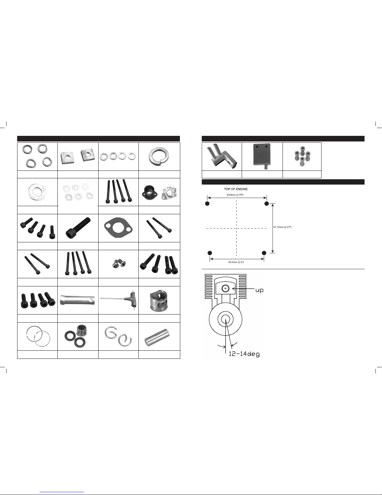
THOR 45 PETROL ENGINE MOUNTING BOLT PATTERN AND TIMING
Use this scale template to lay out the mounting bolt
pattern onto your model's firewall.
Use this information to help reset the timing, should it be necessary.
WIth the piston at TDC, the sensor 'plug' in the prop adapter should be
straight down. Next, adjust the sensor mount so that the sensor is 12º-14º to
the right (when looking at the front of the engine). A timing gauge attached
to the prop shaft should be used to help align the sensor mount correctly.
THR45-0230
M8 Crank Retaining Split Washer
THR45-0480
M5 Flat Washers
THR45-0460
M5x55 Mounting Bolts
THR45-0320
Carb Mount & Velocity Stack
THR45-0050
M5x15 Cylinder Head Bolts
THR45-0240
M8x40 Propeller Bolt
THR45-0350
Carburettor Insulator
THR45-0390
M5x40 Carb Bolts
THR45-0250
M4x40 Prop Retaining Bolts
THR45-0130
M5x25 Crankcase Bolts
THR45-0220
M8 Crank Retaining Washer
THR45-0140
M5 Crankcase Bolt Spring Washers
THR45-0400
M5 Silencer Mounting Nuts
THR45-0260
M4 Split Washers for Prop Adapter
THR45-0270
M4x10 Prop Adapter Bolts
THR45-0490
Spark Plug Wrench
THR45-0500
Hex Wrench
THR45-0060
Piston
THR45-0420
Pitt's-Style Silencer (Optional)
THOR 45 PETROL ENGINE REPLACEMENT PARTS LIST, CONTINUED....
THR45-0430
Quiet Silencer (Optional)
THR45-0070
Piston Ring Set
THR45-0080
Small End Bearing with Thrust Washers
THR45-0100
Circlips - Piston
THR45-0090
Piston Pin
THR45-0440
M5x60 Silencer Bolts (STD)
THOR 45 PETROL ENGINE REPLACEMENT PARTS LIST, CONTINUED....
THR45-0450
Engine Mount Spacers
THR45-0470
Sensor Mounting Screws
 Loading...