

Thomson CSF Detexis JETSAT User Manual

JETSAT FCC APPLICATION FCC ID: OYAJETSAT
EXHIBIT F

FCC ID: OYAJETSAT
23-25-22
THOMSON-CSF DETEXIS
System User Manual
JETSAT
SATCOM AERO I AES
NE 918.882 AN August 18/98
T1

FCC ID: OYAJETSAT
23-25-22
THOMSON-CSF DETEXIS
SYSTEM USER MANUAL
NOTE
IF ANY UNUSUAL OR SPECIAL SERVICE PROBLEMS ARISE,
CONTACT THOMSON-CSF DETEXIS.
Mailing address : THOMSON-CSF DETEXIS
55, Quai Marcel Dassault
92214 SAINT-CLOUD
FRANCE
PROPRIETARY NOTICE
This document contains proprietary information and such
information may not be disclosed to others for any purpose,
not used for manufacturing purposes without written
permission from THOMSON-CSF DETEXIS.
PN-1
August 18/98

FCC ID: OYAJETSAT
23-25-22
THOMSON-CSF DETEXIS
SYSTEM USER MANUAL
RECORD OF REVISIONS
REV.
NO.
REVISION
DATE
DATE
INSERTED
BY
REV.
NO.
REVISION
DATE
DATE
INSERTED
BY
RR-1/RR-2
August 18/98

FCC ID: OYAJETSAT
23-25-22
THOMSON-CSF DETEXIS
SYSTEM USER MANUAL
SERVICE BULLETIN LIST
The Service Bulletin listed below have been incorporated in this manual.
ATA NO.
(D.E. NO.)
MANUAL
REVISION
NUMBER
MANUAL
REVISION
DATE
COVERAGE
SB-1/SB-2
August 18/98

FCC ID: OYAJETSAT
23-25-22
THOMSON-CSF DETEXIS
SYSTEM USER MANUAL
LIST OF EFFECTIVE PAGES
SUBJECT PAGE DATE
Title Page T1 Aug 18/99
Proprietary
Notice
Record of
Revisions
Service Bulletin
List
List of Effective
Pages
General Table
of Contents
Introduction INTRO-1
Table of
Contents
List of Figures LF1-1
PN-1 Aug 18/99
RR-1
RR-2
SB-1
SB-2
LEP-1
LEP-2
GTC-1
GTC-2
INTRO-2
INTRO-3
INTRO-4
INTRO-5
INTRO-6
TC1-1
TC1-2
TC1-3
TC1-4
LF1-2
1 Aug 18/99
2 Aug 18/99
3 Aug 18/99
4 Aug 18/99
5 Aug 18/99
6 Aug 18/99
7 Aug 18/99
8 Aug 18/99
9 Aug 18/99
10 Aug 18/99
11 Aug 18/99
Aug 18/99
Blank
Aug 18/99
Blank
Aug 18/99
Aug 18/99
Aug 18/99
Blank
Aug 18/99
Aug 18/99
Aug 18/99
Aug 18/99
Aug 18/99
Aug 18/99
Aug 18/99
Aug 18/99
Aug 18/99
Blank
Aug 18/99
Blank
SUBJECT PAGE DATE
12 Aug 18/99
13 Aug 18/99
14 Aug 18/99
15 Aug 18/99
16 Aug 18/99
17 Aug 18/99
18 Aug 18/99
19 Aug 18/99
20 Aug 18/99
21 Aug 18/99
22 Aug 18/99
23 Aug 18/99
24 Aug 18/99
25 Aug 18/99
26 Aug 18/99
27 Aug 18/99
28 Aug 18/99
29 Aug 18/99
30 Aug 18/99
31 Aug 18/99
32 Aug 18/99
33 Aug 18/99
34 Aug 18/99
35 Aug 18/99
36 Aug 18/99
37 Aug 18/99
38 Aug 18/99
39 Aug 18/99
40 Aug 18/99
41 Aug 18/99
42 Aug 18/99
43 Aug 18/99
44 Aug 18/99
45 Aug 18/99
46 Aug 18/99
47 Aug 18/99
48 Aug 18/99
49 Aug 18/99
50 Blank
Table of
Contents
TC100-1
TC100-2
Aug 18/99
Aug 18/99
LEP-1
August 18/98

FCC ID: OYAJETSAT
23-25-22
THOMSON-CSF DETEXIS
SYSTEM USER MANUAL
SUBJECT PAGE DATE
List of Figures LF100-1
LF100-2
101 Aug 18/99
102 Aug 18/99
103 Aug 18/99
104 Aug 18/99
105 Aug 18/99
106 Aug 18/99
107 Aug 18/99
108 Aug 18/99
109 Aug 18/99
110 Aug 18/99
111 Aug 18/99
112 Aug 18/99
113 Aug 18/99
114 Aug 18/99
115 Aug 18/99
116 Blank
Aug 18/99
Blank
SUBJECT PAGE DATE
Table of
Contents
TC300-1
TC300-2
301 Aug 18/99
302 Aug 18/99
303 Aug 18/99
304 Aug 18/99
305 Aug 18/99
306 Aug 18/99
307 Aug 18/99
308 Aug 18/99
309 Aug 18/99
310 Aug 18/99
311 Aug 18/99
312 Aug 18/99
313 Aug 18/99
314 Aug 18/99
315 Aug 18/99
316 Aug 18/99
Aug 18/99
Blank
Table of
Contents
TC200-1
TC200-2
201 Aug 18/99
202 Aug 18/99
203 Aug 18/99
204 Aug 18/99
205 Aug 18/99
206 Aug 18/99
207 Aug 18/99
208 Aug 18/99
209 Aug 18/99
210 Aug 18/99
211 Aug 18/99
212 Aug 18/99
213 Aug 18/99
214 Aug 18/99
215 Aug 18/99
216 Aug 18/99
217 Aug 18/99
218 Aug 18/99
219 Aug 18/99
220 Aug 18/99
221 Aug 18/99
222 Aug 18/99
223 Aug 18/99
224 Blank
Aug 18/99
Aug 18/99
Table of
Contents
TC400-1
TC400-2
401 Aug 18/99
402 Aug 18/99
403 Aug 18/99
404 Aug 18/99
405 Aug 18/99
406 Aug 18/99
407 Aug 18/99
408 Aug 18/99
409 Aug 18/99
410 Aug 18/99
411 Aug 18/99
412 Aug 18/99
413 Aug 18/99
414 Aug 18/99
415 Aug 18/99
416 Aug 18/99
417 Aug 18/99
418 Aug 18/99
419 Aug 18/99
420 Aug 18/99
Aug 18/99
Aug 18/99
LEP-2
August 18/98

FCC ID: OYAJETSAT
23-25-22
THOMSON-CSF DETEXIS
SYSTEM USER MANUAL
GENERAL TABLE OF CONTENTS
Section/Title Page
INTERFACES..............................................................................................................1
SYSTEM CONFIGURATION INITIALIZATION .......................................................101
(M)CTU HANDSETS USER INSTRUCTIONS.........................................................201
BASIC MAINTENANCE USER GUIDE ...................................................................301
SDU INTEGRATED MAINTENANCE TERMINAL MENU .......................................401
GTC-1/GTC-2
August 18/98

23-25-22
1. General
A. AES Interfaces
This documents describes all the system interfaces from the user point of
view.
The other interfaces between AES LRUs e.g. SDU to HLD and HLD to IGA
are define in the installation manual.
System interfaces are described by sections
FCC ID: OYAJETSAT
THOMSON-CSF DETEXIS
SYSTEM USER MANUAL
INTRODUCTION
− AES A/C avionics interfaces
− AES cabin interfaces
− AES cockpit interfaces
− AES maintenance interfaces
B. Initialization
Telecommunication systems providing access to Public Switched
Telecommunication Ne twork (PSTN) with a high le vel of availability, security
and sharing common resources require a very reliable organization, in
INMARSAT AERO systems a part of this organization takes place in the AES
configuration.
As some AES configuration parameters impact the AES use ( such as Log_on
policy, prefered GES, etc), AES configuration is made available to the AES
user during the initialization process.
The JETSAT AES needs initialization before to be able to successfully log_on
and access to the private or public telecommunication networks via the
INMARSAT satellite constellation and the associated Ground Earth Stations
connected to these networks.
JETSAT initialization is made using SDU tables describing the user’s choices
and/or by using SDU’s strap option pins programmed in accordance with the
user’s choices.
INTRO-1
August 18/98

FCC ID: OYAJETSAT
23-25-22
THOMSON-CSF DETEXIS
SYSTEM USER MANUAL
(1) SDU Tables
JET initialization includes to provide accurate data to correctly fill the
following SDU tables with:
− System Configuration Table / Module (SCM), see note 1
− AES tables
• System table (ST)
• Owner/Operator Requirements Table (ORT)
• Owner/Operator Requirement Table Phone Book (ORTPB)
− MCDU pages table, see note 2.
Note 1: System configuration can alternatively be done using the strap
option pin programming ( see next paragraph). It is the user choice.
Note 2: MCDU SATCOM pages have only to be filled if the use of
MCDU(s) with SATCOM is requested by the user. MCDU SATCOM pages
can alternatively be initialized via the MCDU, in this case the user should
refer to MCDU user manual.
This JETSAT user manual provides the user with all the information
requested to correctly initialize all these tables.
SDU tables can be accessed and modified by several means:
− Airborne Data Loader connected to the SDU rear connector ADL port.
− Portable Data Loader connected to the SDU PDL front panel port.
− Maintenance Terminal ( PC based) connected to one of the two SDU
− maintenance ports ( serial RS232 link).
SDU ports are defined in the inter-wiring section of the JETSAT
Installation Manual.
(2) Pin programming/strap option definition:
If the user selects the pin programming or strap option, he has to wire the
pin programming SDU pins in accordance with his choices for JETSAT
initialization. Pin programming definitions are given in this manual.
INTRO-2
August 18/98

FCC ID: OYAJETSAT
23-25-22
THOMSON-CSF DETEXIS
SYSTEM USER MANUAL
C. (M)CTU/Handsets user instructions
This manual provides detailed instructions to use JETSAT CTU or
MCTU/digital handsets package.
D. Basic maintenance user guide
While not a maintenance manual, the present document provides the JETSAT
user with a description of all the maintenance messages displayed on the SDU
front panel screen and on the maintenance terminal when connected to one of
the two SDU maintenance ports
E. Other requirements to operate JETSAT
Obviously other items are requested to successfully operate JETSAT, JETSAT
installation is not described in this document, so the installer/user must refer to
JETSAT Installation Manual for detailed installation instructions , the list below
briefly indicates the minimum items requested to operate JETSAT:
Power supply: could be 28 DC or 115 v 400 Hz, both type of units are
available from DETEXIS. P/N and characteristics of both types are defined in
the JETSAT Installation Manual. Type selection has to be made before
ordering JETSAT in accordance with the aircraft primary power network to be
used. It is not recommended to mixed the two type of units.
It is requested that all the SATCOM LRUs are connected to the A/C primary
power network through a unique breaker, this will avoid erroneous failure
declarations when other JETSAT LRUs are powered after the SDU finished
the JETSAT system self tests.
A/C primary power network must comply with power supply applicable
chapters of DO160 D / ED14D specifications. Environmental conditions
JETSAT LRUs comply with are defined in the JETSAT Installation Manual
Cooling: JETSAT LRUs require air cooling . Air flows for each JETSAT LRU
are defined in JETSAT Installation Manual.
Navigation Data: To steer the antenna beam in the satellite direction JETSAT
requires Navigation Data from at least one A/C Inertial Navigation System (
JETSAT offers two INS ARINC 429 inputs). This (these) A/C Inertial
Navigation System(s) must comply with ARINC 704-6 specification. If no
ARINC 704-6 Inertial Navigation System is available, one can use the JETSAT
NRF option by ordering the JETSAT SDU with the NRU option and the
JETSAT NRU-F external antenna module. SDU/NRU LRU and NRU-F module
P/Ns and characteristics are defined in JETSAT Installation Manual . JETSAT
Navigation Data capabilities and NRF functionality’s are described in the
JETSAT product description manual, while INS and NRU-F wiring and
installation are available in the JETSAT Installation Manual.
INTRO-3
August 18/98

FCC ID: OYAJETSAT
23-25-22
THOMSON-CSF DETEXIS
SYSTEM USER MANUAL
ICAO address: The user must provide the ICAO address to the SDU and the
external CTU . The ICAO address is used by SATCOM to identify the A/C
“telephone number”. The ICAO address could be provided using the dedicated
25 SDU discrete inputs socalled “ICAO add. Interfaces” or via the SDU
dedicated ARINC 429 “AES ID serial input”. Both possibilities are described in
this manual. The choice is from the user. The CTU has only discrete inputs/pin
strapping capability.
INTRO-4
August 18/98

FCC ID: OYAJETSAT
23-25-22
THOMSON-CSF DETEXIS
SYSTEM USER MANUAL
2. Presentation of the manual
This manual is divided into separate sections and sub-sections as follows:
PRELIMINARY PAGES
− Title page
− Proprietary notice
− Record of revisions
− Service Bulletin list
− List of effective pages
− General table of contents
− Introduction
− Glossary
SYSTEM INTERFACES
SYSTEM CONFIGURATION INITIALIZATION
(M)CTU, HANDSETS USER INST RUCTIONS
BASIC MAINTENANCE USER GUIDE
SDU INTEGRATED MAINTENANCE TERMINAL MENU
INTRO-5
August 18/98

23-25-22
3. Glossary
FCC ID: OYAJETSAT
THOMSON-CSF DETEXIS
SYSTEM USER MANUAL
:
INTRO-6
August 18/98

FCC ID: OYAJETSAT
23-25-22
THOMSON-CSF DETEXIS
SYSTEM USER MANUAL
SYSTEM INTERFACES
TABLE OF CONTENTS
Page
1. Overall System Interfaces.......................................................................................1
2. AES A/C avionics interfaces synopsys.................................................................... 3
A. Synopsys ..........................................................................................................3
B. AES A/C avionics interfaces summary..............................................................4
C. EAS A/C avionics interfaces detailed................................................................5
(1) IRS interfaces...........................................................................................5
(2) NRU-F Interfaces......................................................................................6
(3) CFDS/CMC Interfaces..............................................................................6
(4) ADL interfaces..........................................................................................7
(5) APM interfaces.........................................................................................7
(6) FMC interfaces.........................................................................................8
(7) AES ID interfaces.....................................................................................8
(8) WOW interfaces.......................................................................................9
(9) Motion Sensor interfaces........................................................................10
(10) ICAO Address interfaces........................................................................10
(11) Status interfaces.....................................................................................12
(12) SDU Cross-talk interfaces......................................................................13
3. Cabin interfaces....................................................................................................15
A. Overall cabin interfaces (synopsys)................................................................15
B. Cabin interfaces summary..............................................................................16
C. Cabin interfaces detailed................................................................................16
(1) External CTU interfaces .........................................................................16
(2) Digital handset interfaces.......................................................................16
(3) Modem equipped devices.......................................................................17
(4) CPDF interfaces.....................................................................................17
(5) Analogue handset interfaces..................................................................18
4. Maintenance Interfaces.........................................................................................19
A. Maintenance interfaces summary...................................................................19
B. Maintenance interfaces detailed.....................................................................19
TC1-1
August 18/98

FCC ID: OYAJETSAT
23-25-22
THOMSON-CSF DETEXIS
SYSTEM USER MANUAL
(1) RS232 Serial Line interfaces..................................................................19
(2) Indicator interfaces.................................................................................20
(3) Push-buttons interfaces..........................................................................21
(4) LCD Display interfaces...........................................................................21
(5) Test headset interfaces..........................................................................22
(6) PDL interfaces........................................................................................22
(7) Op/Test interfaces..................................................................................23
5. Cockpit Interfaces .................................................................................................23
A. Overall cockpit interfaces................................................................................23
B. Cockpit data transmission interfaces..............................................................26
(1) Summary................................................................................................26
(2) Detail......................................................................................................26
C. Voice transmissions........................................................................................27
(1) Summary................................................................................................28
D. MCDU interfaces.............................................................................................28
(1) Physical interfaces .................................................................................28
(2) Function..................................................................................................28
E. Analogue voice interfaces...............................................................................29
(1) Physical interfaces .................................................................................29
F. RMP interfaces...............................................................................................30
(1) Physical interfaces : ...............................................................................30
6. SATCOM Pages....................................................................................................31
A. General presentation ......................................................................................31
(1) SATCOM MCDU MAIN MENU page......................................................31
(2) SATCOM DIRECTORY Page.................................................................33
(3) CATEGORY NUMBERS Pages.............................................................34
(4) SATCOM MANUAL DIAL Page..............................................................37
B. Placing an Air to Ground Call..........................................................................40
(1) Cockpit calls by manual dialing ..............................................................40
(2) Cockpit call with pre-selected numbers..................................................41
(3) Adding a phone number in the Directory................................................44
TC1-2
August 18/99

FCC ID: OYAJETSAT
23-25-22
THOMSON-CSF DETEXIS
SYSTEM USER MANUAL
C. Ground to Air Call Set-up (Figure 8)...............................................................45
D. HOLD function (Figure 9)................................................................................47
E. Call termination (Figure 10) ............................................................................48
(1) Satcom call is established (not on HOLD)..............................................48
(2) Satcom call is established (on HOLD)....................................................48
TC1-3/TC1-4
August 18/98

FCC ID: OYAJETSAT
23-25-22
THOMSON-CSF DETEXIS
SYSTEM USER MANUAL
LIST OF FIGURES
Figure 1 - System interface synopsys............................................................................2
Figure 2 - AES A/C avionics interfaces synopsys..........................................................3
Figure 3 - Cabin interfaces synopsys ..........................................................................15
Figure 4 - Audio Control Panel....................................................................................24
Figure 5 - AMU/SDU interface.....................................................................................25
Figure 6 - Cockpt interfaces synopsys.........................................................................26
Figure 7 - Call initiation on ACP...................................................................................39
Figure 8 - Ground to AIR Call......................................................................................46
Figure 9 - HOLD Function............................................................................................47
Figure 10 - Call termination .........................................................................................49
LF1-1/LF1-2
August 18/98

FCC ID: OYAJETSAT
23-25-22
THOMSON-CSF DETEXIS
SYSTEM USER MANUAL
SYSTEM INTERFACES
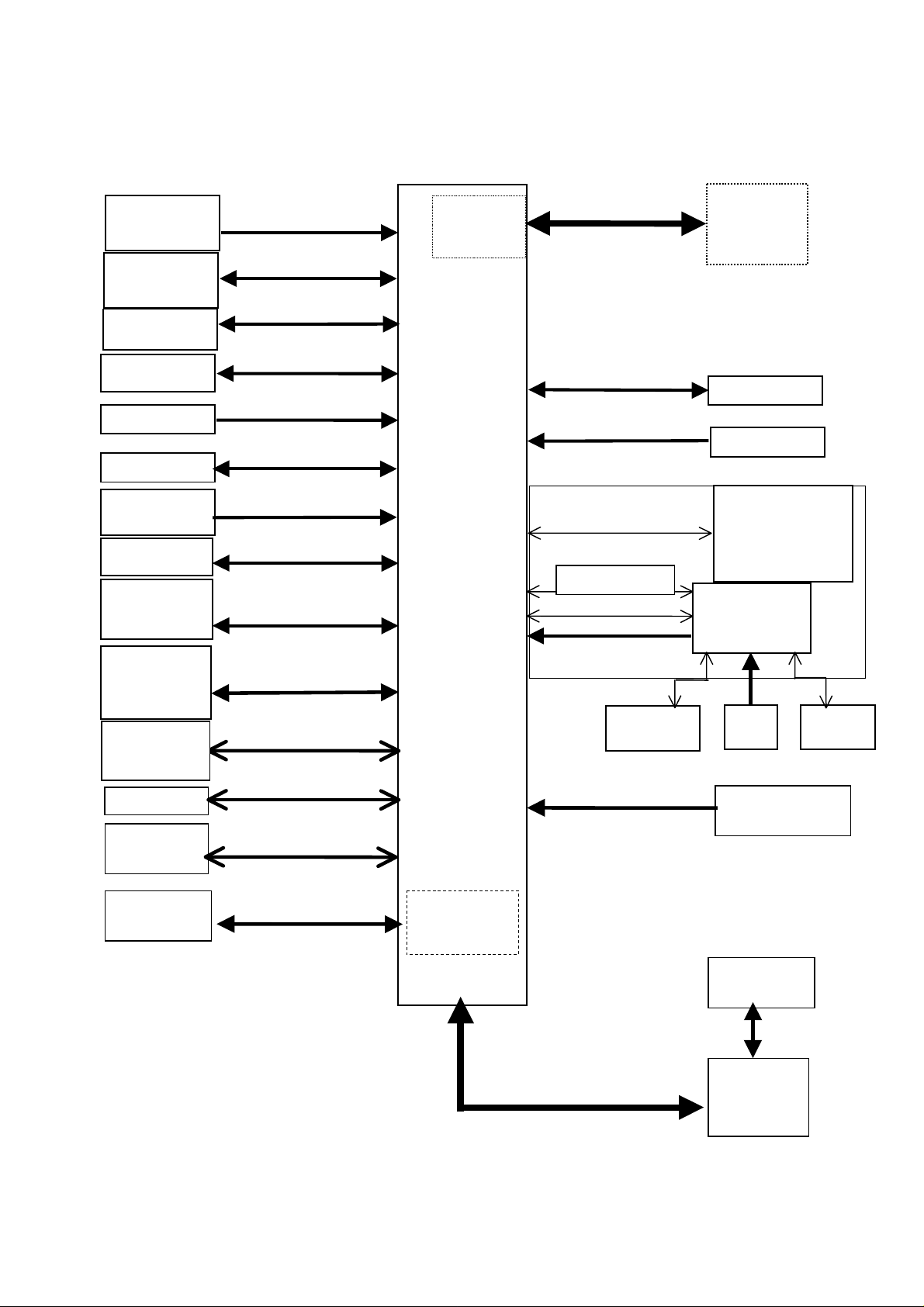
1. Overall System Interfaces
All JETSAT user interfaces are located in the SDU.
SDU/HLD/IGA interfaces are described in the JETSAT installation manual.
Page 1
August 18/99
FCC ID: OYAJETSAT
23-25-22
(
)
THOMSON-CSF DETEXIS
SYSTEM USER MANUAL
IRS
#1, #2
CMU/ACARS
/ATSU #1, #2 or
AFIS
MCDU
#1, #2, #3
CFDS
ADL
RMP
FMC
#1, #2
CPDF
DISCRETE
SIGNALS &
STATUS
ARINC 429
ARINC 429
ARINC 429
ARINC 429
ARINC 429
ARINC 429
ARINC 429
ARINC 429
DISCRETES
NRU
(option)
SDU
RF+DC
ARINC 429
DISCRETES
ARINC 429
FRONT PANEL
DISCRETES
Analogue DTMF
RS232 LINE
ARINC 429
NRU-F
ANTENNA
option
STU #2
AES ID
DISPLAY
INDICATORS
PUSH-BUTTON
SWITCHES
CONNECTOR
Audio
Management
System
Cockpit
Maintenance
device
2 Fax or PC
4 Analogue
handsets
Up to 32 Digital
handsets
ANALOGUE
&DISCRETES
RS232 LINE
2 x DTMF 2-wire
4 x 4-wire
4 S0 TELEPHONE
LOOPS
MCTU
(option)
CEPT-E1
HEADSET
DATA BUS
TEST
PDL
APM
Up to 128 Digital
handsets
External
CTU(s)
PC MAT
System interface synopsys
Figure 1
Page 2
August 18/99
FCC ID: OYAJETSAT
23-25-22
,
THOMSON-CSF DETEXIS
SYSTEM USER MANUAL
Note 1 : The use of MCTU or External CTU is mutually exclusive.
Note 2 : The use of Analogue or Digital Handsets is mutually exclusive.
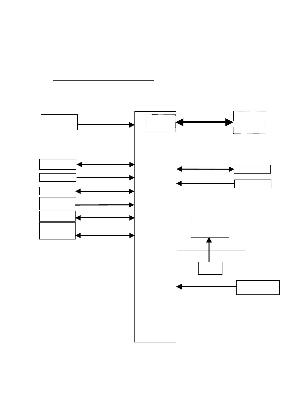
2. AES A/C avionics interfaces synopsys
A. Synopsys
IRS
#1
#2
CFDS
ADL
RMP
FMC
#1, #2
CPDF
DISCRETE
SIGNALS &
STATUS
ARINC 429
ARINC 429
ARINC 429
ARINC 429
ARINC 429
ARINC 429
DISCRETES
NRU
(option)
SDU
RF+DC
ARINC 429
DISCRETES
ARINC 429
FRONT PANEL
CONNECTOR
NRU-F
ANTENNA
(option)
SDU #2
AES ID
PDL
DATA BUS
AES A/C avionics interfaces synopsys
Figure 2
APM
Page 3
August 18/99

FCC ID: OYAJETSAT
23-25-22
THOMSON-CSF DETEXIS
SYSTEM USER MANUAL
B. AES A/C avionics interfaces summary
DESIGNATION
IRS
(Inertial Reference system)
NRU-F RF 1 TT-NRUF2a
CFDS/CMC
(Centralized Fault Display
System/Central Maintenance
I/F TYPE INPUT OUTPUT REFERENCE
ARINC 429
(HI speed)
ARINC 429
(LO speed)
2 ARINC 704
1 1 ARINC 604
ARINC624
ABD 048
Computer)
ADL
(Airborne Data Loader)
Data Loader
Link A and B
APM
(Aircraft personalit y Module)
FMC
(Flight Management
ARINC 429
(HI speed)
Discrete 2 ARINC 615
Discrete 1 8 ARINC 761
ARINC 429
(LO speed)
1 1 ARINC 615
2 ARINC 702
Computer)
AES ID ARINC 429
(HIorLO
1 TBD
speed)
WOW
(Weig ht On Wheels)
Motion Sensor
(Motion Sensor/Sensor
Discrete 3 ARINC 761
Discrete 2 ARINC 741
Program Select)
ICAO Addresses Discrete 24+1 ARINC 761
Status
(Fail warning,
Cockpit voice unavailable,
Discrete 7 ARINC 761
Cabin voice unavailable,
Packet data unavailable,
Packet data low speed
available, Link not ready,
SATCOM Inoperable)
Strap option Discrete 39 ARINC 761
• Multi Control
• BITE/Status
SDU Cross-talk ARINC 429
DSS
(Dual System Selection
Dual System Disable)
ARINC 429
(HI speed)
ARINC 429
(LO speed)
(HI speed)
Discrete 1 1 ARINC 761
1
1
1 1 ARINC 761
Page 4
August 18/99
FCC ID: OYAJETSAT
23-25-22
THOMSON-CSF DETEXIS
SYSTEM USER MANUAL
C. EAS A/C avionics interfaces detailed
(1) IRS in terfaces
(a) Physical interfaces
Two high speed ARINC 429 input interfaces are available to connect
up to two IRS.
The Strap option pins or the System Configuration Module (SCM)
define which IRS (#1 and/or #2) is connected to the SDU.
(b) Function
Data sent by the IRS’s ( in conformance with the ARINC 704
characteristics) is used by the SDU to :
− determine aircraft position and attitude in order to calculate the
pointing angles in elevation and azimuth towards the satellite to be
used by the HLD to drive the antenna.
− determine the aircraft velocity and the true heading, to calculate
the theoretical frequency Doppler shift between aircraft and
satellite in order to compensate RX and TX frequencies of the
AES transceiver.
If both primary and secondary IRS are connected to the SDU, data
from primary IRS are used, but the SDU will automatically use data
from secondary IRS if those from primary IRS are detected failed.
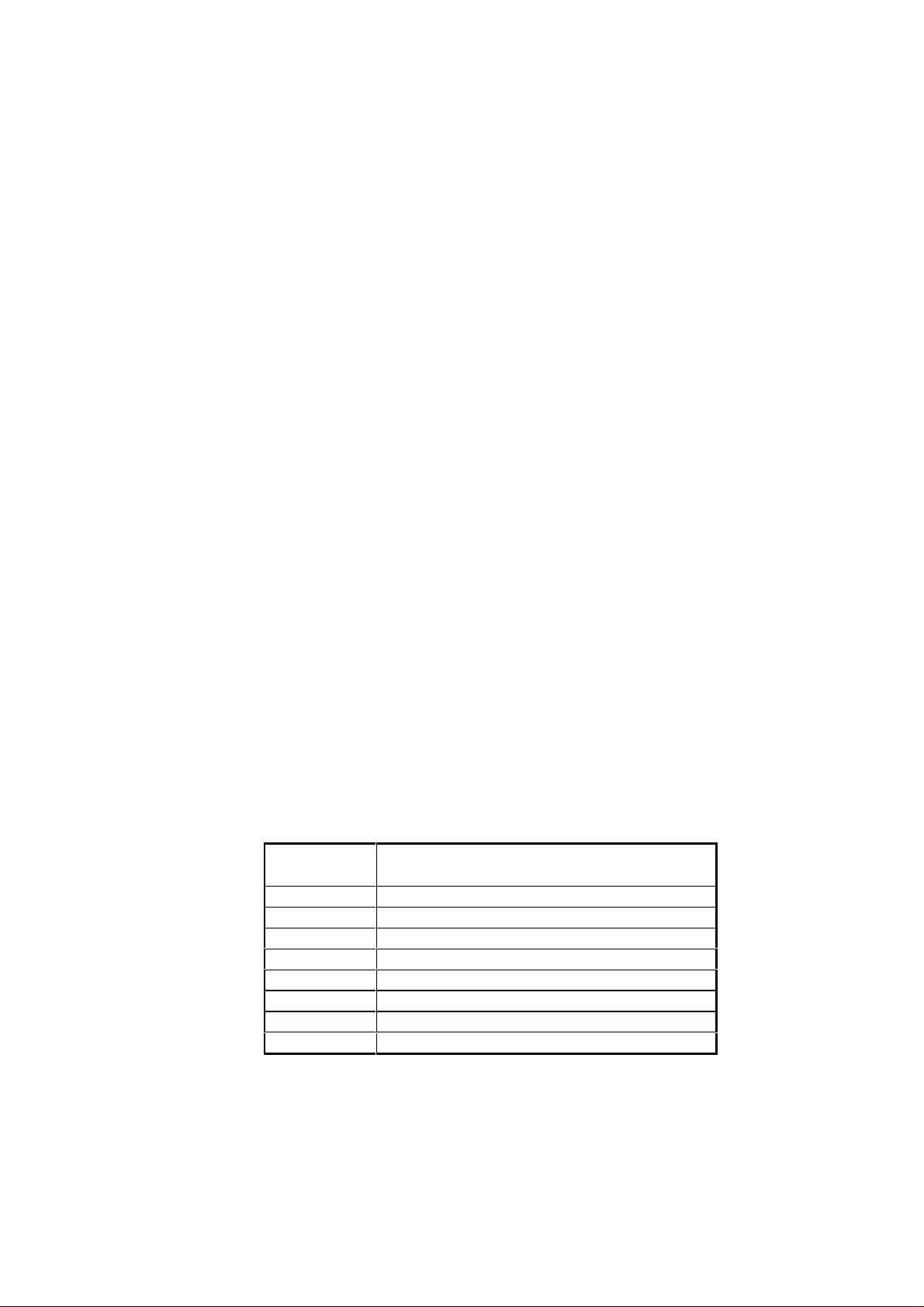
IRS labels are :
LABEL
NUMBER
310 Present position Latitude
311 Present position Longitude
312 Ground speed
313 Track angle
314 True heading
324 Pitch angle
325 Roll angle
361 Inertial altitude
DESIGNATION
Page 5
August 18/99

23-25-22
(2) NRU-F Interfaces
(a) Physical interfaces
The NRU-F interface consists in a single RF link which permits to
connect a NRU-F antenna, if the NRU module option is installed.
(b) Function
The NRU-F comprises a GPS antenna including input filter/LNA and
a three axes magnetometer.
The data received from the NRU-F allows to determine the aircraft
velocity, attitude and position (with the same accuracy as the one
provided by the IRS) when no IRS is available on the aircraft.
If both IRS’s and NRU-F are connected to the SDU, the IRS’s
information are priority share.
FCC ID: OYAJETSAT
THOMSON-CSF DETEXIS
SYSTEM USER MANUAL
(3) CFDS/CMC Interfaces
(a) Physical interfaces
Two low speed ARINC 429 interfaces (one input and one output)
permit to connect one CFDIU/CMC (Type 1 system as defined in
ABD 048).
The Strap option pins or the System Configuration Module (SCM)
define if a CFDIU/CMC is connected to the SDU.
(b) Function
CFDS function purpose is to analyze all BIT in order to detect, to
store in non-volatile memory and to report to CFDUI/CMC LRU
failures.
The system operates in two modes, normal mode and interactive
mode as specified in ABD 048 :
− In normal mode, the SDU continuously sends to the CFDIU/CMC
fault messages that indicates identity of a in-flight failed LRU to be
replaced, or identities of in-flight suspect LRU’s.
− In interactive mode, an operator can ask SDU :
• More failed LRU’s : f ailed LRU detected during the last 63 legs
and failed LRU detected on ground
Page 6
August 18/99
FCC ID: OYAJETSAT
23-25-22
THOMSON-CSF DETEXIS
SYSTEM USER MANUAL
• Details about a failure : aircraft, date, time, trouble shooting
data,…
• To start a system test to detect all current failures.
The SDU BITE format conforms with the ARINC 604 characteristics.
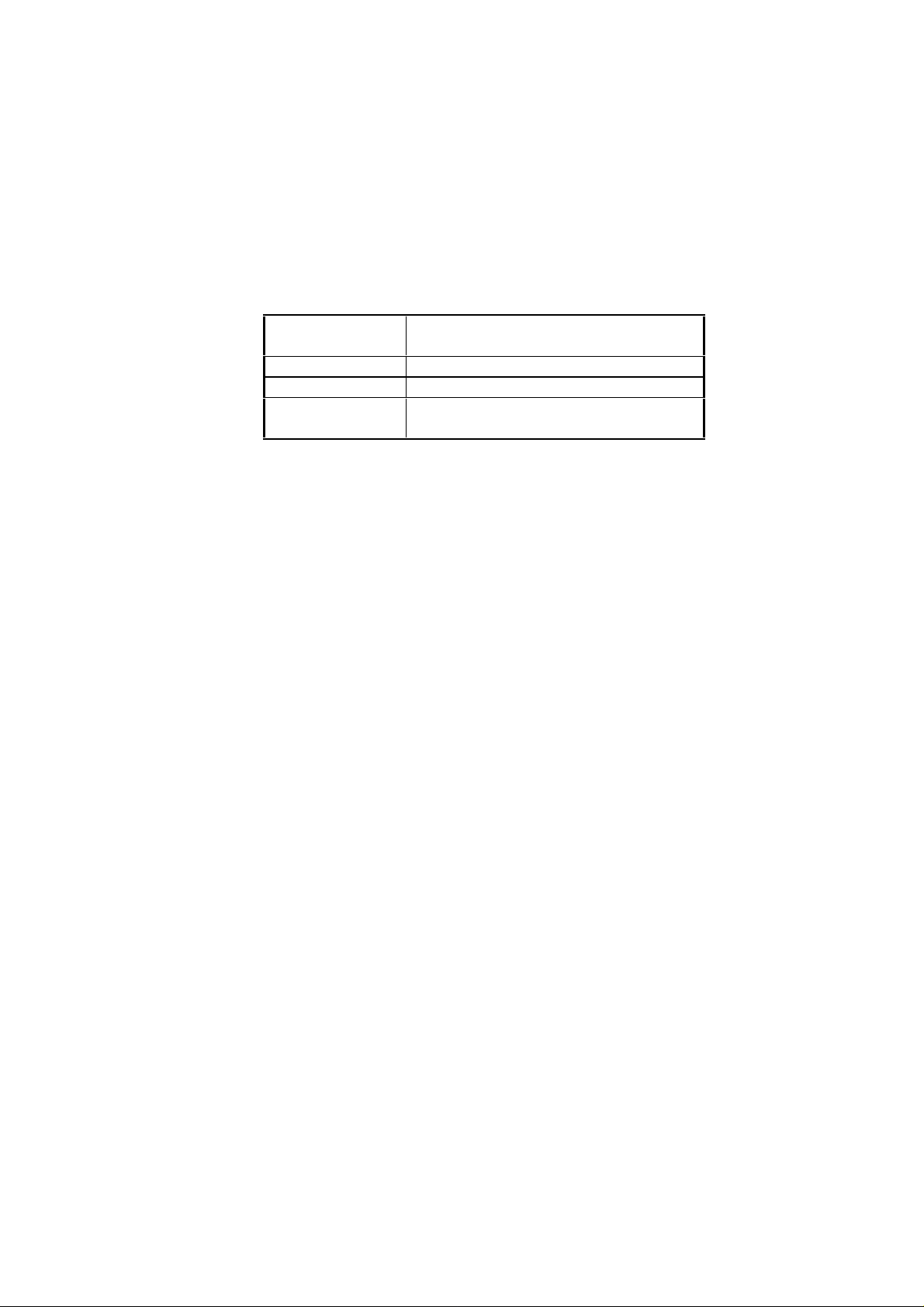
Related labels are :
LABEL
NUMBER
350-356, 377 Fault Summary Words
227 Command Summary Word
125, 126, 155,
301-303
(4) ADL interfaces
(a) Physical interfaces
Two high speed ARINC 429 interfaces (one input and one output)
and two discrete signals permit to connect one ADL unit.
(b) Function
The ADL allows the operator to modify the operational software of
the SDU, the AES Tables (ORT) or the SCM by uploading the
required version from a 3-1/2 inch floppy diskette.
DESIGNATION
Status word
The SDU address label is : 307
The data transfer protocol complies with the ARINC 615
characteristics.
Data transfer is authorized only when the SDU detects both discrete
strapped together.
(5) APM in terfaces
(a) Physical interfaces
Provision for nine discrete signals (one input and height outputs) and
associated circuitry is available in the SDU, in conformance with the
ARINC 607 characteristics supplement 2.
Page 7
August 18/99

23-25-22
(b) Function
Due to lack of definition in A 761 specification the related software
function is not implemented at time of issue.
(6) FMC interfaces
(a) Physical interfaces
Provision for two low speed ARINC 429 interfaces (two inputs) are
available in the SDU.
(b) Function
Due to lack of definition the related software function is not
implemented at time of issue.
FCC ID: OYAJETSAT
THOMSON-CSF DETEXIS
SYSTEM USER MANUAL
(7) AES ID interfaces
(a) Physical interfaces
One high or low speed ARINC 429 input interface permits to connect
one source of ICAO address
( MODE S, ...).
The Strap option pins or the System Configuration Module (SCM)
define the availability of ICAO Address from an ARINC 429 bus, and
the ARINC 429 bus speed.
(b) Function
The ICAO address is acquired at the SDU power up and stored to
non volatile memory. The acquired ICAO address has not to be
changed till next SDU power up.
The SDU selects the means of receiving the ICAO Address
information, in order of decreasing precedence, as follows :
− From CMU #1
− From CMU #2
− From AES ID
Page 8
August 18/99
FCC ID: OYAJETSAT
23-25-22
THOMSON-CSF DETEXIS
SYSTEM USER MANUAL
− From the APM
− From 25 ICAO Address discrete
Related labels are :
LABEL
NUMBER
275, 276 ICAO Addr ess
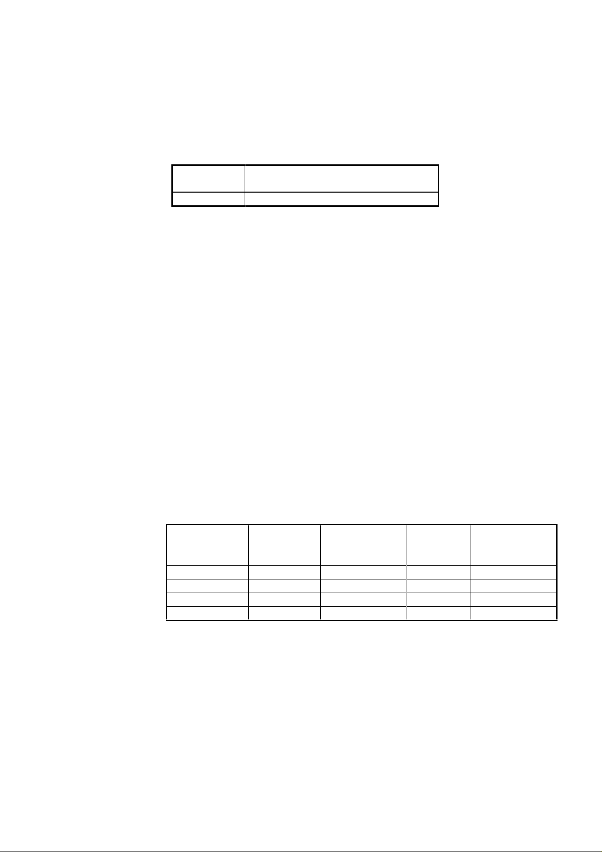
(8) WOW interfaces
(a) Physical interfaces
Three discrete inputs are available to enable the SDU to determine
whether or not the aircraft is on-ground.
(b) Function
− Input #1 and input #2 indicate the aircraft situation (in-flight or on-
ground), to authorize maintenance operations on the ground only
(such as data loading ), and to inhibit power up self tests during
flight to shorter the JETSAT “warmer time” when JETSAT is
powered lately during flight and calls have to be made urgently.
DESIGNATION
− “ Program Select ” input defines the “ true ” or “ false ” state of
inputs #1 and #2 (“ false ” state in open circuit and “ True ” state
when strapped with pin MP15K “ Common Address ”).
INPUT #1, #2 PROGRAM
SELECT
DC ground DC ground IN-FLIGHT No No
Open circuit DC ground ON-GROUND Yes Yes
DC ground Open circuit ON-GROUND Yes Yes
Open circuit Open circuit IN-FLIGHT No No
AIRCRAFT
SITUATION
SELF
TEST at
Power up
Maintenance
operations
authorized
Page 9
August 18/99

FCC ID: OYAJETSAT
23-25-22
THOMSON-CSF DETEXIS
SYSTEM USER MANUAL
(9) Motion Sensor interfaces
(a) Physical interfaces
Two discrete inputs are available to enable the SDU to determine
whether or not the aircraft is in motion.
(b) Function
− One input “ Motion Sensor ” defines the aircraft position, not used
by the application
− One input “ Sensor Program Select ” defines the “ true ” or “ false ”
state of “ Motion Sensor ” input (“ True ” state in open circuit and
“ false ” state when strapped with pin MP15K “ Common
Address ”)
These discrete are not used in the application software. They comply
with the ARINC 761 characteristics.
MOTION SENSOR
DC ground DC ground IN MOTION
Open circuit DC ground STOPPED
DC ground Open circuit STOPPED
Open circuit Open circuit IN MOTION
(10) ICAO Address interfaces
(a) Physical interfaces
Twenty five discrete inputs permit the SDU to acquire the ICAO
address :
− Twenty four inputs for the address bits “ bit #1 (MSB) to bit #24
(LSB) ”
SENSOR
PROGRAM
SELECT
AIRCRAFT
POSITION
− One input “ Common Address ”
(b) Physical interfaces
The acquired ICAO address is used to identify the AES.
Page 10
August 18/99

FCC ID: OYAJETSAT
23-25-22
THOMSON-CSF DETEXIS
SYSTEM USER MANUAL
Address bits left open circuit are on the binary “ one ” state and
address bits strapped with the “ common Address ” input are on the
binary “ zero ” state.
The ICAO address is acquired at the SDU power up and stored to
non volatile memory. The acquired ICAO address has not to be
changed till next SDU power up.
These discrete comply with the ARINC 761 characteristics.
PIN number Interpretation Signal name
MP13C ICAO address MSB
MP13D
MP13E
MP13F
MP13G
MP13H
MP13J
MP13K
MP14D
MP14E
MP14F
MP14G
I_ICAO_1
MP14H
MP14J
MP14K
MP15A
MP15B
MP15C
MP15D
MP15E
Page 11
August 18/99

FCC ID: OYAJETSAT
23-25-22
THOMSON-CSF DETEXIS
SYSTEM USER MANUAL
PIN number Interpretation Signal name
MP15F
MP15G
MP15H
MP15J ICAO address LSB
MP15K A/C Address common
I_ICAO_24
ICAOCOM
(11) Status interfaces
(a) Physical interfaces
Seven discrete outputs (0-28V) define the SDU or AES status :
(b) Function
− SATCOM fail warning : This discrete indicates that the SDU has
detected a JETSAT essential default, from the CBIT.
− Cockpit voice unavailable : This discrete indicates the AES is not
logged on and/or a failed PBIT result (Cockpit CODEC failed)
and/or no AMS is wired.
− Cabin voice unavailable : This discrete indicates the AES is not
logged on and/or a link loss with the MCTU or external CTU.
− Packet data unavailable : This discrete indicates the AES cannot
support such functionality (AES class 1 or 2 identified during logon
process).
− Packet data low speed only available : This discrete indicates the
AES cannot support such functionality (AES class 1 or 2 identified
during logon process).
− SATCOM inoperable : This discrete indicates that the SDU has
detected a JETSAT fatal error
− Link not ready : This discrete indicates that JETSAT is not logged
These discrete, when grounded, indicate a fail or unavailable
situation. At power up they all indicate a fail or unavailable situation.
They comply with the ARINC 761 characteristics.
Page 12
August 18/99
 Loading...