

Page 1

Power
Ethernet
DSL-
1
Internet
4
3
2
SHDSL Configuration Guide
R8.2 and higher
Thomson Gateway
Page 2

Page 3

Thomson Gateway
SHDSL Configuration Guide
R8.2 and higher
Page 4

Copyright
Copyright ©1999-2006 Thomson. All rights reserved.
Distribution and copying of this document, use and communication of its contents is not permitted without written authorization
from Thomson. The content of this document is furnished for informational use only, may be subject to change without notice,
and should not be construed as a commitment by Thomson. Thomson assumes no responsibility or liability for any errors or
inaccuracies that may appear in this document.
Thomson Telecom Belgium
Prins Boudewijnlaan, 47
B-2650 Edegem
Belgium
http://www.thomson-broadband.com
Trademarks
The following trademarks are used in this document:
SpeedTouch™ is a trademark of Thomson.
DECT is a trademark of ETSI.
Bluetooth® word mark and logos are owned by the Bluetooth SIG, Inc.
Ethernet™ is a trademark of Xerox Corporation.
Wi-Fi® and the Wi-Fi logo are registered trademarks of the Wi-Fi Alliance. "Wi-Fi CERTIFIED", "Wi-Fi ZONE", "Wi-Fi Alli-
ance", their respective logos and "Wi-Fi Protected Access" are trademarks of the Wi-Fi Alliance.
UPnP™ is a certification mark of the UPnP™ Implementers Corporation.
Microsoft®, MS-DOS®, Windows® and Windows NT® are either registered trademarks or trademarks of Microsoft Corpo-
ration in the United States and/or other countries.
Apple® and Mac OS® are registered trademarks of Apple Computer, Incorporated, registered in the United States and
other countries.
UNIX® is a registered trademark of UNIX System Laboratories, Incorporated.
Adobe®, the Adobe logo, Acrobat and Acrobat Reader are trademarks or registered trademarks of Adobe Systems, Incor-
porated, registered in the United States and/or other countries.
Other brands and product names may be trademarks or registered trademarks of their respective holders.
Document Information
Status: v2.0 (June 2008)
Reference: E-DOC-CTC-20080313-0001
Short Title: Config Guide: SHDSL R8.2 and higher
Page 5

E-DOC-CTC-20080313-0001 v2.0
i
Contents
About this SHDSL Configuration Guide ................................... 1
1 Introduction..................................................................................3
2 SHDSL Overview .........................................................................5
2.1 Standard Compliancy...................................................................................... 5
2.2 Transmission Convergence (TC) Layers .......................................................... 8
2.3 Capacity Characteristics ............................................................................... 10
3 Thomson SHDSL Devices ......................................................... 13
3.1 Portfolio Overview ........................................................................................ 13
3.2 Front Panel.................................................................................................... 14
3.3 Back Panel .................................................................................................... 15
3.4 LED Behaviour and Connector Layout .......................................................... 16
4 Configuring and Operating the SHDSL Interface ................... 19
4.1 Simple Back-to-Back Setup ........................................................................... 20
4.2 SHDSL CLI 1-2-3 ............................................................................................ 25
4.3 CLI Reference ................................................................................................ 27
5 Modem Options......................................................................... 35
5.1 Introduction .................................................................................................. 35
5.2 Modem-Option Reference ............................................................................. 36
Page 6

E-DOC-CTC-20080313-0001 v2.0
ii
Contents
Page 7

E-DOC-CTC-20080313-0001 v2.0
1
About this SHDSL Configuration Guide
About this SHDSL Configuration Guide
Used Symbols
Terminology
Generally, a Thomson Gateway of the SHDSL product portfolio will be referred to as a Thomson SHDSL
device in this SHDSL Configuration Guide.
Typographical Conventions
Following typographical convention is used throughout this manual:
This sample text indicates a hyperlink to a Web site.
Example: For more information, visit us at www.thomson-broadband.com
.
This sample text indicates an internal cross-reference.
Example: If you want to know more about guide, see “1 Introduction” on page 7”.
This sample text indicates an important content-related word.
Example: To enter the network, you must authenticate yourself.
This sample text indicates a GUI element (commands on menus and buttons, dialog box elements, file
names, paths and folders).
Example: On the File menu, click Open to open a file.
Documentation and software updates
Thomson continuously develops new solutions, but is also committed to improving its existing products.
For more information on Thomson's latest technological innovations, documents and software releases, visit
us at http://www.thomson-broadband.com
.
Disclaimer IP addresses
All Internet Protocol (IP) hosts that are part of examples in this document are assumed to be RFC1918
Category 1 hosts. They require no access to hosts in other enterprises or the Internet at large.
As such, all IP addresses are assumed to be of type private and may not be used outside this private context.
In addition, any use of actual IP addresses shown in documentation examples are inadvertent and
concomitant.
A note provides additional information about a topic.
A caution warns you about potential problems or specific precautions that need to be taken.
Page 8

E-DOC-CTC-20080313-0001 v2.0
2
About this SHDSL Co
nfiguration Guide
Page 9

E-DOC-CTC-20080313-0001 v2.0
3
1| Introduction
1 Introduction
Introduction
SHDSL is short for Symmetric High-speed Digital Subscriber Line and is one of the several DSL flavours
offered by telecommunication providers. Its main difference with the more popular Asymmetric Digital
Subscriber Line (ADSL) variant is that it provides symmetrical data rates.
The intention of this SHDSL Configuration Guide is the following:
Highlight the most important features and capabilities of Thomson’s SHDSL product portfolio.
Provide a legend for back panel and connector layout.
Explain the relevant SHDSL aspects in detail.
Familiarize the reader with Thomson’s SHDSL CLI and network OS via a simple back-to-back setup.
For in-depth SHDSL information, the interested reader is encouraged to read the relevant SHDSL standards,
which are publicly available on the ITU-T website: www.itu.int/ITU-T/
. See also section “2.1 Standard
Compliancy” on page 5 for more information.
Inevitably, in explaining the operation and configuration of the Thomson SHDSL devices, certain higher layer
aspects (bridging, routing, QoS, VLANs and so on) will be touched. These will be explained if necessary, but
for specific details the appropriate documentation must be consulted.
SHDSL features
All Thomson SHDSL devices support following SHDSL-specific features:
Flexible and cost-effective SHDSL product portfolio: 1-pair, 2-pair, 3-pair and 4-pair flavours.
Symmetrical data rates ranging from 192 kbps up to 5696 kbps per wire-pair.
Single hardware platform supporting two Transmission Convergence (TC) layers:
ATM over SHDSL: ATM cells mapped in SHDSL framing.
EFM over SHDSL: Ethernet frames mapped in SHDSL framing.
In case the TC-layer is set to ATM, support of the optional SHDSL-bonding feature, referred to as (ATM)
M-pair operation. Both the 2-wire/4-wire mode as well as the scalable M-pair mode are supported.
In case the TC-layer is set to EFM, support of the optional Physical Medium Entity Aggregation Function
(PAF).
Full standard compliancy: ITU-T G.991.2, ITU-T G.994.1 and IEEE 802.3-2005.
Capable of operating in either Customer Premises Equipement (CPE) mode or Central Office (CO) mode:
CPE mode (default): to connect to SHDSL DSLAM lines.
CO mode: to cover back-to-back applications (one device in CPE mode connected to a second device
in CO mode).
Per default interoperable with the most important DSLAM vendors.
Extended interoperability achieved via modem options.
Support of following auto-detection mechanisms:
Automatic synchronization to a specific rate or within a specified range (192 kbps - 5696 kbps).
Auto-detection of the TC-layer (ATM/EFM).
Single pair or M-pair operation via the auto-wire option in both ATM and EFM.
Automatic detection of the master-pair in case of ATM M-pair operation.
Page 10

E-DOC-CTC-20080313-0001 v2.0
4
1| Introduction
Terminology
This paragraph briefly describes several DSL-related terms that are used throughout this Configuration
Guide:
DSL line: this term refers to a copper wire-pair that can be connected to a DSL modem.
DSL link: this term refers to a DSL circuit in the SHDSL chip. Each DSL link is terminated on the back-
panel connector and can be connected to a single DSL line. A device with one DSL link is also referred to
as a single pair device. Similarly, a device with two DSL links is referred to as a 2-pair device, and so on.
DSL interface: Thomson SHDSL devices implement a logical DSL interface. Multiple DSL links can be
added to a single DSL interface. This way, the DSL interface can be used to refer to a single link or
multiple aggregated links.
DSL profile: this term refers to a set of configuration parameters that are applied to a single DSL interface.
It is assumed that the configuration parameters that are part of a DSL profile only change sporadically.
Internal channel: this term refers to an internal communication channel between the SHDSL chip and the
network processor (NWP). A DSL interface is associated with an internal channel, via which it exchanges
data traffic with the network processor. In practice, this internal channel is realized via a Utopia bus.
ATM M-pair operation: multiple SHDSL links are assigned to a single DSL interface and as such constitute
an ATM M-pair group. Data-traffic originating from the NWP will be byte interleaved over the members of
the M-pair group via the SHDSL bonding technique.
EFM M-pair operation: multiple SHDSL links are assigned to a single DSL interace and as such constitute
an EFM Physical medium entity Aggregation Function (PAF) group. Similar as with ATM M-pair, datatraffic originating from the NWP will be segmented over the members of the PAF group via the EFM PAF
function. From a high level perspective, the intention of an ATM M-pair group or an EFM-PAF group is
achieving a higher bandwidth for a given loop length or obtaining a longer reach for a given bandwidth.
For this reason, the terms EFM-PAF, EFM M-pair and PAF group will be used interchangeably in the
remainder of this document.
Overview
The remainder of this SHDSL Configuration Guide is organized as follows:
Chapter 2 provides a short overview of the SHDSL standards. It briefly explains the operation of the ATM and
EFM TC-layers and gives tentative figures of SHDSL’s link capacity.
The next chapter describes Thomson’s SHDSL product portfolio and explains the LED behaviour on the front
panel and the connectors on the back panel.
Chapter 4 explains the configuration and operation of the Thomson SHDSL interface in detail, using the
Command-Line Interface (CLI). The description of a simple back-to-back setup helps the SHDSL beginner to
get started, while the more experienced reader can find specific information in an alphabetic list of SHDSL
CLI commands.
Finally, the last chapter pays special attention to Thomson’s SHDSL modem options. These options are
mainly intended to achieve interoperability in cases where the CO’s SHDSL implementation deviates from
standard.
This results in the following chapters:
Topi c Page
“2 SHDSL Overview” 5
“3 Thomson SHDSL Devices” 13
“4 Configuring and Operating the SHDSL Interface” 19
“5 Modem Options” 35
Page 11

E-DOC-CTC-20080313-0001 v2.0
5
2| SHDSL Overview
2 SHDSL Overview
Overview
This chapter covers following topics:
2.1 Standard Compliancy
Introduction
Thomson’s SHDSL implementation attempts to be as compliant as possible with the relevant standards in
force at the time of product release. The main reason for this goal is to achieve as much interoperability with
as many as possible counterparts.
In particular, Thomson SHDSL devices are compliant with:
ITU-T G.991.2 and its annexes, which mainly specify:
The SHDSL specific framing, line-coding and possible data rates.
The ATM TC-layer.
The 2-wire/4-wire operation.
The more recent and scalable ATM M-pair operation.
ITU-T G.994.1, which specifies the handshake procedures for DSL transceivers.
IEEE 802.3-2005 Clauses 56, 61 and 63, which specify:
The EFM TC-layer.
The EFM M-pair operation.
Specific aspects of ITU-T G.994.1 (G.Hs), which are needed for SHDSL EFM operation.
Topi c Page
“2.1 Standard Compliancy” 5
“2.2 Transmission Convergence (TC) Layers” 8
“2.3 Capacity Characteristics” 10
Page 12

E-DOC-CTC-20080313-0001 v2.0
6
2| SHDSL Overview
ITU-T G.991.2
SHDSL is mainly standardized by ITU-T Recommendation G.991.2. This recommendation is often abbreviated
as G.SHDSL. The latest standardization activities resulted in Annex F and G, which allow for higher data rates
and are referred to as G.SHDSL bis. This recommendation also specifies the optional 2-wire/4-wire operation
and the more scalable M-pair mode, which are referred to as SHDSL bonding or simply G.Bond.
Following table provides an overview of the sections of ITU-T G.991.2 that are relevant to the Thomson
SHDSL devices:
ITU-T G.994.1
SHDSL is a complex link layer and to use it in a flexible way, some form of “auto-negotiation” is needed. For
this function, SHDSL transceivers rely on ITU-T Recommendation G.994.1, often abbreviated as G.Hs. This
recommendation specifies the mechanism and procedures that DSL transceivers must use to exchange their
individual capabilities and to select a common mode of operation. The recommendation is an integral part of
the start-up procedure for ITU-T G.991.2.
The Thomson SHDSL devices are compliant with following standard:
Standard Title Popular term
ITU-T G.991.2 (12/2003) Single-pair high-speed digital subscriber line (SHDSL)
transceivers
Annex A Regional requirements - Region 1 (North America) G.SHDSL
Annex B Regional requirements - Region 2 (Europe)
Annex E.9 TPS-TC for ATM transport
Annex F Region 1 requirements for payload data rates up to
5696 kbps
G.SHDSL bis
Clause 8.2 Data interleaving in M-pair mode G.Bond
ITU-T G.991.2 Am. 1 (07/2004) Single-pair high-speed digital subscriber line (SHDSL)
transceivers Amendment 1
ITU-T G.991.2 Am. 2 (02/2005) Single-pair high-speed digital subscriber line (SHDSL)
transceivers Amendment 2
Annex G Region 2 requirements for payload data rates up to
5696 kbps
G.SHDSL bis
Standard Title Popular term
ITU-T G.994.1 (02/2007) Handshake procedures for digital subscriber line
(DSL) transceivers
G.Hs
Page 13

E-DOC-CTC-20080313-0001 v2.0
7
2| SHDSL Overview
IEEE 802.3-2005
IEEE 802.3-2005 Clause 56 introduces Ethernet in the First Mile (EFM). Several physical layers are specified for
optical fiber media, voice grade copper pairs and passive optical networks (PONs). It also introduces an
Operations, Administration and Maintenance (OAM) mechanism to be used on point-to-point Ethernet links
(E-OAM). Clause 61 specifies items common to the 10PASS-TS and 2BASE-TL EFM systems which apply to
voice grade copper media. This clause also specifies the optional PAF function. Clause 63 is 2BASE-TL
specific, which is the EFM system used in combination with SHDSL modulation.
Following IEEE 802.3-2005 clauses are relevant to the Thomson SHDSL devices:
Standard Tit le
IEEE 802.3-2005 (12/2005) Part 3: Carrier Sense Multiple Access with Collision Detection (CSMA/CD)
access method and physical layer specifications
Clause 56 Introduction to Ethernet for subscriber access networks (Ethernet in the First
Mile)
Clause 61 Physical Coding Sublayer (PCS), Transmission Convergence (TC) sublayer,
and common specifications, type 10PASS-TS and type 2BASE-TL
Clause 63 Physical Medium Attachment (PMA) and Physical Medium Dependent
(PMD), type 2BASE-TL
Page 14

E-DOC-CTC-20080313-0001 v2.0
8
2| SHDSL Overview
2.2 Transmission Convergence (TC) Layers
Introduction
Thomson SHDSL devices support two Transmission Convergence (TC) layers: the traditional Asynchronous
Transfer Mode (ATM) TC and the newer Ethernet in the First Mile (EFM) TC.
A single platform such as the SHNT-F is capable of operating in any of the following configurations:
ATM TC on top of a single SHDSL link.
ATM TC on top of multiple SHDSL links configured in a single SHDSL 4-wire group or a scalable SHDSL
M-pair group.
EFM TC on top of a single SHDSL link.
EFM TC configured in a PAF group consisting of at least one and possibly multiple SHDSL links.
The remainder of this section briefly explains each combination and enumerates the main advantages and
disadvantages.
ATM TC - Single pair
In case the ATM TC-layer is enabled on a single SHDSL link, a stream of 53 byte ATM cells is converted into an
octet stream which is fed into the SHDSL transceiver.
Advantages:
ATM is a well proven technology.
This solution is multiprotocol, e.g. PPPoE over ATM, PPP over ATM (PPPoA) or Ethernet over ATM
(ETHoA).
Disadvantages:
Fixed 5 byte cell overhead + variable AAL5/fixed RFC 1483 overhead.
ATM TC - M-pair
If multiple SHDSL links are assigned to a DSL interface, then it can operate in 4-wire mode or in the scalable
M-pair mode. In this case, the cell stream is byte-interleaved over the two pairs (4-wire mode) or over the M
pairs (M-pair mode). This aggregation method is sometimes referred to as SHDSL bonding. This technique
requires that the SHDSL links within the bonding group are all in data mode and synchronized to the same
rate.
Advantages:
Deployed and proven track record.
No extra overhead due to M-pair operation.
Disadvantages:
The links must synchronize to the same rate.
All links must be simultaneously up.
Page 15

E-DOC-CTC-20080313-0001 v2.0
9
2| SHDSL Overview
EFM TC - Single pair
In case the EFM TC-layer is enabled on a single SHDSL link, a stream of variable-sized Ethernet frames is first
converted into 64 byte EFM fragments. Next, these fragments are 64/65-octet encoded and fed into the
SHDSL transceiver. This mechanism is also referred to as “basic EFM framing”.
Advantages:
Very low encapsulation overhead.
Disadvantages:
This solution is single protocol, i.e. Ethernet only (including PPPoE).
EFM TC - M-pair
If multiple SHDSL links are assigned to a DSL interface, a so-called PAF group is formed. Prior to applying
basic EFM framing, Ethernet frames are segmented in PAF segments. The individual PAF segments are
forwarded to any of the available SHDSL links within the PAF group. Each SHDSL link performs the further
EFM processing similar as for basic EFM framing.
Advantages:
For data transport it is sufficient that a single link is in showtime.
Links that are part of a PAF group may synchronize to different rates, which may differ to a ratio of four.
Disadvantages:
Slightly higher overhead if compared to basic EFM framing
Utopia data bus
In order to support the two TC-layers (ATM and EFM) on a single hardware platform, the Utopia bus is
selected as data bus for the communication between the SHDSL chip and the NWP. This Utopia bus enables
the customer to seamlessly switch between the two TC-layers.
The Utopia data bus is an ATM bus, implying that in case of EFM mode an ATM layer is still used internally.
The SHDSL chip terminates the ATM layer and expects to receive the data traffic on a PVC with address 0.32
(VPI.VCI). For more information, see “ Internal operation” on page 26.
Page 16

E-DOC-CTC-20080313-0001 v2.0
10
2| SHDSL Overview
2.3 Capacity Characteristics
Introduction
This section gives an idea of the maximum link capacity of a Thomson SHDSL device in case the TC-layer is
set to EFM.
Two cases should be considered:
EFM TC - Single pair
EFM TC - M-pair
G.SHDSL offers symmetrical data rates from 192 kbps up to 2312 kbps in 64 kbps increments. If G.SHDSL bis
is used, symmetrical data rates from 768 kbps up to 5696 kbps can be achieved, again in 64 kbps increments.
These values apply to a single DSL link. If multiple DSL links are used, the aggregated bandwidth can be up to
22.8 Mbps (four DSL links). However, the overhead due to EFM framing or the EFM M-pair operation must
also be taken into account.
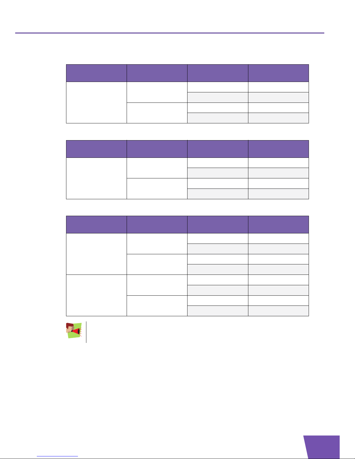
EFM TC - Single pair
Following table shows the maximum link capacity of a single DSL link for different (untagged) Ethernet frame
sizes. We assume that the DSL link has a fixed bandwidth of 5696 kbps.
EFM TC - M-pair
Following table shows the maximum link capacity of a PAF group with two DSL links for different (untagged)
Ethernet frame sizes and different PAF fragment sizes. We assume that the PAF group contains two DSL links,
each with a fixed bandwidth of 5696 kbps. This results in an aggregated bandwidth of 11 392 kbps.
Ethernet frame size (bytes) Maximum link capacity (fps) Encapsulation efficiency (%)
64 10 028 90
128 5 235 94
256 2 676 96
512 1 353 97
1024 680 98
1518 459 98
Disclaimer: the values in this table are for information purposes only. Actual results may vary,
depending on many factors (e.g. noise environment, distance to DSLAM, DSLAM configuration and
others).
Ethernet frame
size (bytes)
Maximum link capacity (fps)
PFS = 64 PFS = 128 PFS = 256 PFS = 512
64 19 243 19 243 19 243 19 243
128 9 687 10 245 10 245 10 245
256 4 860 5 141 5 294 5 294
512 2 434 2 575 2 652 2 692
Page 17

E-DOC-CTC-20080313-0001 v2.0
11
2| SHDSL Overview
1024 1 217 1 289 1 327 1 347
1518 824 868 895 909
PFS is short for PAF Fragment Size (octets). By default, the PFS is set to 256 octets.
Disclaimer: the values in this table are for information purposes only. Actual results may vary,
depending on many factors (e.g. noise environment, distance to DSLAM, DSLAM configuration and
others).
Ethernet frame
size (bytes)
Maximum link capacity (fps)
PFS = 64 PFS = 128 PFS = 256 PFS = 512
Page 18

E-DOC-CTC-20080313-0001 v2.0
12
2| SHDSL Overview
Page 19

E-DOC-CTC-20080313-0001 v2.0
13
3| Thomson SHDSL Devices
3 Thomson SHDSL Devices
Overview
This chapter covers following topics:
3.1 Portfolio Overview
SHDSL product portfolio
This document is applicable to following Thomson SHDSL devices:
TG605s
ST620s
TG628s
Product capabilities and limits
Following table lists the capabilities and the upper limits for the different SHDSL devices:
Topi c Page
“3.1 Portfolio Overview” 13
“3.2 Front Panel” 14
“3.3 Back Panel” 15
“3.4 LED Behaviour and Connector Layout” 16
Capabilities TG605s
(1-pair)
TG605s
(2-pair)
ST620s TG628s
Board Mnemonic (name) SHNT-G SHNT-G SHNT-D SHNT-F
Product ID (PID) 1 0 0 0
Maximum number of DSL links 1 2 2 4
Maximum number of DSL interfaces 1 1 1 1
Maximum number of DSL profiles 2 4 4 4
For more information on the terminology used in this table, see “ Terminology” on page 4.
Page 20

E-DOC-CTC-20080313-0001 v2.0
14
3| Thomson SHDSL D
evices
3.2 Front Panel
Layout
The following illustration shows the front panel of a Thomson SHDSL device (TG628s):
LEDs
The Thomson SHDSL device is equipped with a number of LEDs on its front panel, indicating the state of the
device during normal operation.
The following table shows the meaning of the different LEDs of a TG628s, which supports four DSL links and
has a LED per DSL link:
Ethernet
Power
3
4
DSL-1
2
Internet
Indicator name Description
Power Power switched on or off, bootloader activity and device malfunctions
Ethernet Presence of an Ethernet connection and Ethernet activity
DSL-4 DSL activity on DSL link 3
DSL-3 DSL activity on DSL link 2
DSL-2 DSL activity on DSL link 1
DSL-1 DSL activity on DSL link 0
Internet Presence of an Internet connection and Internet activity
Page 21

E-DOC-CTC-20080313-0001 v2.0
15
3| Thomson SHDSL Devices
3.3 Back Panel
Layout
Following illustration shows the back panel of the Thomson Gateway:
Buttons and connectors
The Thomson Gateway is equipped with the following buttons and connectors on its back panel.
Listed from left to right:
Power socket
On/Off switch
Serial interface
Reset button (to reset the device to the manufacturing defaults)
Four Ethernet connectors
DSL connectors (for example two in case of a TG628s)
Reset
ON
OFF
2 3 41
Console22V DC DSL-0 DSL-1
Page 22

E-DOC-CTC-20080313-0001 v2.0
16
3| Thomson SHDSL D
evices
3.4 LED Behaviour and Connector Layout
DSL LED behaviour
The behaviour of the DSL LEDs indicates the different phases in the DSL start-up process:
DSL connector
The pins of the DSL connector are numbered from left to right as shown in following illustration:
Two types of DSL connectors are used:
RJ11: this connector uses only one pair of pins (pins 3&4) in a 6-pin jack. RJ11 supports a single DSL line.
RJ14: this connector uses two pairs of pins (pins 3&4 and pins 2&5) in a 6-pin jack. RJ14 supports two
DSL lines.
Signal-to-pin assignment
The signal-to-pin assignment is as follows:
TG605s (1-pair variant):
Step DSL link status LED state
1 Silent Off
2 Sending G.Hs tones Green - Blinking at 2 Hz
3 G.Hs message exchange Green - Blinking at 4 Hz
4 Line training and initializing Green - Blinking at 4 Hz
5 Data mode achieved (showtime) Green - Solid
123456
Connector name
on back panel
Link ID [0..3] RJ11 Pin [1..6] Signal (Tip/Ring)
DSL-0 0 3 Ring
4 Tip
Page 23
E-DOC-CTC-20080313-0001 v2.0
17
3| Thomson SHDSL Devices
TG605s (2-pair variant):
ST620s:
TG628s:
Connector name
on back panel
Link ID [0..3] RJ14 Pin [1..6] Signal (Tip/Ring)
DSL-0 0 3 Ring
4 Tip
32Tip
5 Ring
Connector name
on back panel
Link ID [0..3] RJ14 Pin [1..6] Signal (Tip/Ring)
DSL-0 0 3 Ring
4 Tip
32Tip
5 Ring
Connector name
on back panel
Link ID [0..3] RJ14 Pin [1..6] Signal (Tip/Ring)
DSL-0 0 3 Ring
4 Tip
32Tip
5 Ring
DSL-1 1 2 Tip
5 Ring
2 3 Ring
4 Tip
The layout of connector DSL-1 requires special attention:
Link ID 1 corresponds to pins 2 and 5.
Link ID 2 corresponds to pins 3 and 4.
Page 24

E-DOC-CTC-20080313-0001 v2.0
18
3| Thomson SHDSL D
evices
Page 25

E-DOC-CTC-20080313-0001 v2.0
19
4| Configuring and Operating the SHDSL Interface
4 Configuring and Operating the SHDSL Interface
Introduction
The purpose of this chapter is to explain the configuration and operation of the Thomson SHDSL interface in
detail, via the CLI commands located in the xdsl CLI sub-tree:
The simple back-to-back setup illustrates the CPE and CO mode of SHDSL devices.
The CLI 1-2-3 explains how to establish an SHDSL connection with minimal configuration efforts.
The more experienced reader is provided with the fine details in the CLI reference.
DSL interface and DSL profile
Thomson introduces the concept of an SHDSL interface to allow the configuration of the SHDSL chip for
different use cases and to allow specific decisions during connection establishment. This way, advantage is
taken of the flexibility of the SHDSL chip.
A DSL interface configuration is split in two parts for reasons of convenience:
A first part that is accessed via dedicated CLI interface commands and that may require a change during
device installation.
A second part that is assumed to change only sporadically and that is therefore embedded in a so-called
DSL profile.
Overview
This chapter covers following topics:
Topi c Page
“4.1 Simple Back-to-Back Setup” 20
“4.2 SHDSL CLI 1-2-3” 25
“4.3 CLI Reference” 27
Page 26

E-DOC-CTC-20080313-0001 v2.0
20
4| Configuring and O
perating the SHDSL Inter
face
4.1 Simple Back-to-Back Setup
Introduction
This section describes a simple SHDSL back-to-back setup. A first SHDSL device is operated in CPE mode and
is connected to a second one in CO mode. Both SHDSL devices are configured for transparent bridging.
Back-to-back setup
To create the setup, connect two PCs and two Thomson SHDSL devices as shown in following illustration:
Assumptions
The remainder of this section is based on the following assumptions:
PC1 is configured with IP address 10.0.0.1 and netmask 24.
PC2 is configured with IP address 10.0.0.254 and netmask 24.
The configuration of the SHDSL devices will be done by executing CLI commands over a serial
connection.
Before you start
Before you start, prepare the SHDSL devices as follows:
Reset the Thomson Gateway to the factory defaults and reboot the device:
Set the timeout of the CLI session to a suitable value, e.g. 15 minutes (900 seconds):
COCPE
DSL line(s)
PC2PC1
Ethernet Ethernet
10.0.0.1/24 10.0.0.254/2410.0.0.10/24 10.0.0.20/24
{Administrator}=>:system reset factory=yes proceed=yes
{Administrator}=>:env set var=SESSIONTIMEOUT value=900
Page 27

E-DOC-CTC-20080313-0001 v2.0
21
4| Configuring and Operating the SHDSL Interface
Remove the factory default interfaces and settings that you do not need for the configuration:
Disable the broadcast filter on the bridge. This way, broadcasts (e.g. ARP requests) that arrive on a WAN
interface are correctly received by the SHDSL device (and not dropped):
Make these changes permanent. This will be the starting point for our configuration:
Configure the CO
Configure a Thomson SHDSL device in CO mode as follows:
Configure the prompt to easily identify the device that is being configured:
To configure SHDSL, execute following CLI commands:
Configure the IP address as follows:
Save the configuration:
{Administrator}=>:ip ifdelete intf=dmz1
{Administrator}=>:ip ifdelete intf=guest1
{Administrator}=>:ip ifdelete intf=wan1
{Administrator}=>:ip ipdelete addr=10.0.0.138
{Administrator}=>:ip ipdelete addr=192.168.1.254
{Administrator}=>:eth flush
{Administrator}=>:eth vlan flush
{Administrator}=>:eth bridge ifdelete intf=Internet_8_35
{Administrator}=>:eth bridge ifdelete intf=Internet_0_35
{Administrator}=>:atm ifdelete intf=atm_8_35
{Administrator}=>:atm ifdelete intf=atm_0_35
{Administrator}=>:atm phonebook delete name atm_pvc_8_35
{Administrator}=>:atm phonebook delete name=atm_pvc_0_35
{Administrator}=>:eth bridge config filter=none
{Administrator}=>:saveall
{Administrator}=>:env set var=PS1 value="%env(Usr_Prompt)%groupx[]=>"
=>:env set var=Usr_Prompt value={TG628s-CO}
{TG628s-CO}=>:xdsl ifdetach name=dsl0
{TG628s-CO}=>:xdsl ifdelete name=dsl0
{TG628s-CO}=>:xdsl ifadd name=dsl0 profile=def-co
{TG628s-CO}=>:xdsl add name=dsl0 wirepair=link0
{TG628s-CO}=>:xdsl add name=dsl0 wirepair=link1
{TG628s-CO}=>:xdsl add name=dsl0 wirepair=link2
{TG628s-CO}=>:xdsl add name=dsl0 wirepair=link3
{TG628s-CO}=>:xdsl ifattach name=dsl0
{TG628s-CO}=>:ip ipadd intf=lan1 addr=10.0.0.20 netmask=24 addroute=enabled
{TG628s-CO}=>:saveall
Page 28

E-DOC-CTC-20080313-0001 v2.0
22
4| Configuring and O
perating the SHDSL Inter
face
Configure the CPE
Configure a Thomson SHDSL device in CPE mode as follows:
Configure the prompt to easily identify the device that is being configured:
Configure the IP address as follows:
Save the configuration:
{Administrator}=>:env set var=PS1 value="%env(Usr_Prompt)%groupx[]=>"
=>:env set var=Usr_Prompt value={TG628s-CPE}
{TG628s-CPE}=>:ip ipadd intf=lan1 addr=10.0.0.10 netmask=24 addroute=enabled
{TG628s-CPE}=>:saveall
By default, a Thomson SHDSL device is configured in CPE mode. No extra configuration of SHDSL
is required.
Page 29

E-DOC-CTC-20080313-0001 v2.0
23
4| Configuring and Operating the SHDSL Interface
Result
When the configuration of the devices is finished, following results can be expected:
The DSL LEDs should behave like described in section “ DSL LED behaviour” on page 16 (off - 2 Hz - 4 Hz
- solid green).
Once the SHDSL links achieve showtime, information on the DSL interfaces can be displayed as follows:
{TG628s-CPE}=>:xdsl iflist name=dsl0
DSL-interface: dsl0
-------------State:
-----Modemstate : Up
xDSL Type : SHDSL
xDSL Standard & Annex : ITU-T G.991.2 - Annex: B&G - TPS-TC: EFM
xDSl Line code : 32-TCPAM
PME Aggregation Function (PAF): Enabled - Activated
Aggr BW (Down/Up - kbit/s) : 22784/22784
Eth Frames TX/RX : 1/0
Number of resets : 1
Uptime (Days hh:mm:ss) : 0 Days 00:02:03
Configuration:
-------------Profile : def-cpe
Ul-mode : auto
Wire-mode : auto
Int-channel : dsl0
Interface State : attached
Link Info : 0123
Line Info:
---------Link ID : Link0 Link1 Link2 Link3
Line State : Showtime Showtime Showtime Showtime
Bandwidth(Down/Up - kbit/s) : 5696/5696 5696/5696 5696/5696 5696/5696
Margin Downstream (dB) : 19 19 19 19
Attenuation Downstream (dB) : 1 0 1 0
Power Backoff Upstream (dB) : 6 6 6 6
Tx Power Upstream (dBm) : 8 8 8 8
Tip/Ring Reversal : No No No No
Errored Seconds : 0 0 0 0
Severe Errored Seconds : 0 0 0 0
Loss Of Sync Word Seconds : 0 0 0 0
Unavailable Seconds : 0 0 0 0
{TG628s-CPE}=>
Page 30

E-DOC-CTC-20080313-0001 v2.0
24
4| Configuring and O
perating the SHDSL Inter
face
You should be able to ping from PC1 to PC2 successfully as soon as the SHDSL connection is established.
{TG628s-CO}=>xdsl iflist name=dsl0
DSL-interface: dsl0
-------------State:
-----Modemstate : Up
xDSL Type : SHDSL
xDSL Standard & Annex : ITU-T G.991.2 - Annex: B&G - TPS-TC: EFM
xDSl Line code : 32-TCPAM
PME Aggregation Function (PAF): Enabled - Activated
Aggr BW (Down/Up - kbit/s) : 22784/22784
Eth Frames TX/RX : 2/5
Number of resets : 1
Uptime (Days hh:mm:ss) : 0 Days 00:05:23
Configuration:
-------------Profile : def-co
Ul-mode : EFM
Wire-mode : 4pair
Int-channel : dsl0
Interface State : attached
Link Info : 0123
Line Info:
---------Link ID : Link0 Link1 Link2 Link3
Line State : Showtime Showtime Showtime Showtime
Bandwidth(Down/Up - kbit/s) : 5696/5696 5696/5696 5696/5696 5696/5696
Margin Downstream (dB) : 19 19 19 18
Margin Upstream (dB) : 19 19 19 18
Attenuation Downstream (dB) : 1 0 1 0
Attenuation Upstream (dB) : 1 1 1 1
Power Backoff Downstream (dB) : 6 6 6 6
Power Backoff Upstream (dB) : 6 6 6 6
Tx Power Downstream (dBm) : 8 8 8 8
Tx Power Upstream (dBm) : 8 8 8 8
Tip/Ring Reversal : No No No No
Errored Seconds : 1 1 1 1
Severe Errored Seconds : 1 1 1 1
Loss Of Sync Word Seconds : 0 1 1 1
Unavailable Seconds : 0 0 0 0
{TG628s-CO}=>
Page 31

E-DOC-CTC-20080313-0001 v2.0
25
4| Configuring and Operating the SHDSL Interface
4.2 SHDSL CLI 1-2-3
Introduction
In order to get a Thomson SHDSL device up and running with minimal configuration effort, the Thomson
Gateway is provided with a default SHDSL configuration, configuring the device in CPE mode. The main
characteristics of this default configuration are:
The DSL interface uses the default CPE profile.
All DSL links are added to the DSL interface.
The default TC-layer is EFM.
This section describes how you can quickly modify the default SHDSL configuration.
Basic configuration steps
If you want to quickly modify the default configuration of SHDSL on your Thomson Gateway, execute
following steps:
1 Delete the existing DSL interface.
2 Create a DSL profile. This step is optional, you can also use one of the two default profiles.
3 Create a new DSL interface.
4 Associate DSL links with the newly created DSL interface.
5 Configure the DSL interface. This step is optional, you can also use the default configuration.
6 Activate the DSL interface.
CLI commands
Execute the basic configuration steps to quickly configure a Thomson SHDSL device in CPE mode or
CO mode:
1 Delete the existing DSL interface:
2 Decide which one of the two default DSL profiles you want to use:
def-co: a profile that can be used to configure a device in CO mode.
def-cpe: a profile that can be used to configure a device in CPE mode.
3 Create a new DSL interface and specify the selected DSL profile:
4 Associate all DSL links with the new DSL interface.
For more detailed configuration information, see “4.3 CLI Reference” on page 27.
=>:xdsl ifdetach name=dsl0 (optional)
=>:xdsl ifdelete name=dsl0
=>:xdsl ifadd name=dsl_new profile=def-co
=>:xdsl add name=dsl_new wirepair=link0
=>:xdsl add name=dsl_new wirepair=link1
=>:xdsl add name=dsl_new wirepair=link2
=>:xdsl add name=dsl_new wirepair=link3
Page 32

E-DOC-CTC-20080313-0001 v2.0
26
4| Configuring and O
perating the SHDSL Inter
face
5 Use the default configuration of the DSL interface.
6 Activate the DSL interface.
Internal operation
The Utopia data bus, which is an ATM bus, is used for communication between the SHDSL chip and the NWP.
For correct internal operation in case of EMF TC, an ATM interface with destination PVC 0.32 is required. This
interface is present by default and should not be removed from the configuration. However, if these items
have been removed, they can be created as follows:
Create a phone-book entry for a PVC with VPI.VCI value 0.32:
Create an ATM interface on top of the phonebook entry:
Create an Ethernet bridge port connected to the ATM interface:
=>:xdsl ifattach name=dsl_new
=>:atm phonebook add name=atm_pvc_0_32 addr=0.32
=>:atm ifadd intf=atm_0_32
=>:atm ifconfig intf=atm_0_32 dest=atm_pvc_0_32 ulp=mac
=>:atm ifattach intf=atm_0_32
=>:eth bridge ifadd intf=eth-br-dsl
=>:eth bridge ifconfig brname=bridge intf=eth-br-dsl dest=atm_0_32
=>:eth bridge ifattach intf=eth-br-dsl
Page 33

E-DOC-CTC-20080313-0001 v2.0
27
4| Configuring and Operating the SHDSL Interface
4.3 CLI Reference
Overview
This section describes following SHDSL-related CLI commands:
“:xdsl add” on page 27
“:xdsl delete” on page 27
“:xdsl ifadd” on page 28
“:xdsl ifattach” on page 28
“:xdsl ifconfig” on page 28
“:xdsl ifdelete” on page 29
“:xdsl ifdetach” on page 29
“:xdsl iflist” on page 29
“:xdsl list” on page 31
“:xdsl profile add” on page 32
“:xdsl profile delete” on page 32
“:xdsl profile list” on page 32
“:xdsl profile modify” on page 33
:xdsl add
To assign a DSL link to a DSL interface, execute the command :xdsl add.
Following two parameters must be specified:
name: the name of the DSL interface, which must be readily available and in detached state.
wirepair: the name of a DSL link that is available.
For example, add the DSL links with link ID 0 and link ID 3 to a DSL interface:
:xdsl delete
To remove a DSL link from a DSL interface, execute the command :xdsl delete.
Following two parameters must be specified:
name: the name of the DSL interface, which must be in detached state.
wirepair: the name of the DSL link.
For example, remove the DSL link with link ID 0 from a DSL interface:
=>:xdsl add name=dsl0 wirepair=link0
=>:xdsl add name=dsl0 wirepair=link3
The maximum number of DSL links is limited. For more information, see “ Product capabilities and
limits” on page 13.
=>:xdsl delete name=dsl0 wirepair=link0
Page 34

E-DOC-CTC-20080313-0001 v2.0
28
4| Configuring and O
perating the SHDSL Inter
face
:xdsl ifadd
To create a new DSL interface, execute the command :xdsl ifadd.
Following two parameters must be specified:
name: the name of the new DSL interface.
profile: the name of a DSL profile that was created in advance.
For example, create a new DSL interface:
As soon as the new DSL interface is created, i.e. the interface name and profile name are specified, the
configuration parameters are set to default values, which depend on the profile type of the DSL interface. For
more information on the default configuration, see “ :xdsl iflist” on page 29.
:xdsl ifattach
To activate a DSL interface, execute the command :xdsl ifattach. Immediately after activating a DSL
interface, the G.Hs exchange starts.
The following parameter must be specified:
name: the name of the DSL interface to be activated.
For example, activate a DSL interface as follows:
:xdsl ifconfig
To configure a DSL interface, execute the command :xdsl ifconfig. Prior to configuring a DSL interface,
it must be set to detach mode.
The following parameter must be specified:
name: the name of the DSL interface to be configured.
Optionally, following parameters can be specified:
ul-mode: the Transmission Convergence (TC) layer. Two values are possible:
atm: Asynchronous Transfer Mode. This is the default value.
efm: Ethernet in the First Mile.
wire-mode: the DSL wire configuration of the device. The possible values depend on the profile type of
the DSL interface:
If the profile type is CPE, the parameter can be set to 1pair, ..., mpair and auto.
The default value is auto.
If the profile type is CO, the parameter can be set to 1pair, ..., mpair.
The default value is mpair.
=>:xdsl ifadd name=dsl0 profile=test-co
The maximum number of DSL interfaces is limited. For more information, see “ Product
capabilities and limits” on page 13.
=>:xdsl ifattach name=dsl0
In case of previous releases, a device reboot may be necessary to successfully change the
TC-layer from ATM to EFM (or vice versa).
Page 35

E-DOC-CTC-20080313-0001 v2.0
29
4| Configuring and Operating the SHDSL Interface
int-channel: this parameter indicates the internal communication channel used by the DSL interface.
none: if this parameter is set to none, the DSL link(s) can still be initialized but not the ATM channel.
This value is mainly intended for testing purposes only.
dsl0
For example, configure a DSL interface as follows:
:xdsl ifdelete
To delete a DSL interface, execute the command :xdsl ifdelete and specify following parameter:
name: the name of the DSL interface to be deleted.
For example, delete a DSL interface as follows:
:xdsl ifdetach
One may detach a DSL interface to:
Restart the SHDSL link activation procedure.
Modify the configuration of the DSL interface.
Add or delete DSL links to the DSL interface.
To de-activate a DSL interface, execute the command
:xdsl ifdetach and specify following parameter:
name: the name of the DSL interface to be de-activated.
For example, de-activate a DSL interface as follows:
:xdsl iflist
This command shows various information on a DSL interface:
State section: this section is displayed if the interface is attached, irrespective its operational state (up/
down).
Configuration section: this section is displayed irrespective the administrative mode (attached/detached)
and operational state (up/down) of the interface.
Line section: this section is displayed if the interface is up.
=>:xdsl ifconfig name=dsl0 ul-mode=atm wire-mode=2pair int-channel=dsl0
The assigned profile can not be changed with this command. If you want to change the assigned
profile, delete the interface and create a new one with the correct profile.
=>:xdsl ifdelete name=dsl0
=>:xdsl ifdetach name=dsl0
Page 36

E-DOC-CTC-20080313-0001 v2.0
30
4| Configuring and O
perating the SHDSL Inter
face
To display summarized information (only the state sections) on all DSL interfaces, execute the command
:xdsl iflist.
If the TC-layer is set to ATM, following information is displayed:
If the TC-layer is set to EFM, the state section contains an additional PME Aggregation Function (PAF)
field. This field contains two subfields:
Configuration field: two values are possible:
Enabled: this value reflects an auto or M-pair wire-mode.
Disabled: this value reflects the single pair wire-mode.
Operational field: this field is only relevant if the interface is up. Two values are possible:
Activated: this means that PAF is activated when the link is established.
De-activated: this means that PAF is de-activated when the link is established.
If the TC-layer is set to EFM, following information is displayed:
=>:xdsl iflist
DSL-interface: dsl0
-------------State:
-----Modemstate : Up
xDSL Type : SHDSL
xDSL Standard & Annex : ITU-T G.991.2 - Annex: B&G - TPS-TC: ATM
xDSl Line code : 32-TCPAM
Aggr BW (Down/Up - kbit/s) : 22784/22784
ATM Cells TX/RX : 0/153
Number of resets : 1
Uptime (Days hh:mm:ss) : 0 Days 03:50:15
=>
=>:xdsl iflist
DSL-interface: dsl0
-------------State:
-----Modemstate : Up
xDSL Type : SHDSL
xDSL Standard & Annex : ITU-T G.991.2 - Annex: B&G - TPS-TC: EFM
xDSl Line code : 32-TCPAM
PME Aggregation Function (PAF) : Enabled - Activated
Aggr BW (Down/Up - kbit/s) : 11392/11392
Eth Frames TX/RX : 0/0
Number of resets : 1
Uptime (Days hh:mm:ss) : 0 Days 00:01:12
=>
Page 37

E-DOC-CTC-20080313-0001 v2.0
31
4| Configuring and Operating the SHDSL Interface
To display extended information on a specific DSL interface, execute the command :xdsl iflist and
specify the name of a specific interface.
If the profile type is CO, the default parameter values are displayed as follows:
If the profile type is CPE, the default parameter values are displayed as follows:
:xdsl list
To list the DSL links and to which DSL interfaces these links are assigned, execute following command:
=>:xdsl iflist name=dsl0
DSL-interface: dsl0
-------------State:
-----Modemstate : Down
xDSL Type : SHDSL
Configuration:
-------------Profile : test-co
Ul-mode : ATM
Wire-mode : 4pair
Int-channel : dsl0
Interface State : detached
Link Info :
=>
=>:xdsl iflist name=dsl0
DSL-interface: dsl0
-------------State:
-----Modemstate : Down
xDSL Type : SHDSL
Configuration:
-------------Profile : test-cpe
Ul-mode : ATM
Wire-mode : auto
Int-channel : dsl0
Interface State : detached
Link Info :
=>
=>:xdsl list
Available links Assignment
--------------- ---------link0 dsl0
link1 free
link2 free
link3 dsl0
=>
Page 38

E-DOC-CTC-20080313-0001 v2.0
32
4| Configuring and O
perating the SHDSL Inter
face
:xdsl profile add
To create a new DSL profile, execute the command :xdsl profile add.
Following two parameters must be specified:
name: the name of the new DSL profile.
type: the profile type. Two values are possible:
cpe
co
For example, create a new profile as follows:
As soon as a new DSL profile is created, i.e. the name and type parameters are specified, the configuration
parameters are set to default values:
If the type is CO, the default parameter values are the same as the parameters of the profile def-co.
If the type is CPE, the default parameter values are the same as the parameters of the profile def-cpe.
For information on these profiles, see “ :xdsl profile list” on page 32.
:xdsl profile delete
To delete a DSL profile, execute the command :xdsl profile delete. and specify following parameter:
name: the name of the DSL profile to be deleted.
For example, delete a DSL profile as follows:
:xdsl profile list
To display the configuration information of all DSL profiles, execute the command :xdsl profile list.
To display the configuration information of a specific DSL profile, execute the command
:xdsl profile list and specify the name of the DSL profile.
=>:xdsl profile add name=test-profile type=cpe
The maximum number of DSL profiles is limited. For more information, see “ Product capabilities
and limits” on page 13.
=>:xdsl profile delete name=test-profile
A DSL profile can not be deleted if it is in use by a DSL interface. In this case, the DSL interface
must be associated with another profile or deleted first.
Page 39

E-DOC-CTC-20080313-0001 v2.0
33
4| Configuring and Operating the SHDSL Interface
For example, display information on the default DSL profiles as follows:
:xdsl profile modify
To modify the configuration of a DSL profile, execute the command :xdsl profile modify.
Following parameter must be specified:
name: the name of the DSL profile to be modified.
The optional parameters are conditional, i.e. they depend on the profile type:
For both CO and CPE:
paffragmentsize: this parameter is only relevant if EFM will be used as TC-layer mode and a PAF
group is configured. The parameter determines the size in bytes of an Ethernet segment. This is a
value within the range from 64 through 512. The value must also be a multiple of four.
CPE specific parameters: these parameters are referred to as the “physical layer options” or “modem
options”. For more information on these parameters, see “5 Modem Options” on page 35.
atmupfast
automaster
fastdrop
force-enhanced
force-shdsl
=>:xdsl profile list name=def-cpe
Profile: def-cpe
---------------Profile Type : CPE
PAF Fragment Size (octets) : 256
Physical Layer Options (Modem-Options)
ATM Up Fast : disabled
Auto Master : disabled
Fast Drop : disabled
Force Enhanced : disabled
Force SHDSL : disabled
Force TCPAM16 : disabled
Force TCPAM32 : disabled
Line Probing : enabled
Simulate Line Probing : disabled
Vendor Specific Octets : 0000
DISCLAIMER: The xDSL Physical Layer Options are intended for qualified personnel only.
=>:xdsl profile list name=def-co
Profile: def-co
--------------Profile Type : CO
PAF Fragment Size (octets) : 256
xDSL Annex : ITU-T G.991.2 Annex B&G
Min. Bandwidth (kbit/s) : 192
Max. Bandwidth (kbit/s) : 5696
Linecode : Auto
Margins Current (dB) : 0
Margins Current Status : Enabled
Margins Worst (dB) : 0
Margins Worst Status : Disabled
Monitoring : Disabled
=>
Page 40

E-DOC-CTC-20080313-0001 v2.0
34
4| Configuring and O
perating the SHDSL Inter
face
force-tcpam16
force-tcpam32
lineprobing
simulate-lp
vendor-specific
The profile type is CO:
annex: this parameter indicates which regional requirements are taken into account:
af: the regional requirements of ITU-T G.991.2 Annex A&F (North America) are used.
bg: the regional requirements of ITU-T G.991.2 Annex B&G (Europe) are used.
minbw: this is the minimum bandwidth at which the DSL modem should initialize.
maxbw: this is the maximum bandwidth at which the DSL modem should initialize.
linecode: this parameter indicates the line coding used for data transfer:
16-tcpam
32-tcpam
auto
margincurrent: the current noise margin value, expressed in dB.
The noise margin indicates the amount that the noise may increase (and as a consequence the SNR
may decrease), but at which the modem must remain synchronized.
marginworst: the worst noise margin value, expressed in dB.
margincurrentenable: this parameter is used to enable or disable the use of the current noise margin
value.
marginworstenable: this parameter is used to enable or disable the use of the worst noise margin
value.
monitoring: this parameter is used to enable or disable Transmission Quality (SNR) monitoring.
The profile type can not be changed with this command. If you want to change the profile type,
delete the profile and create a new one with the correct profile type.
The configuration of a DSL profile can not be modified if it is used by an attached DSL interface. In
this case, the DSL interface must be detached first.
Page 41

E-DOC-CTC-20080313-0001 v2.0
35
5| Modem Options
5 Modem Options
5.1 Introduction
The modem options, also referred to as the physical layer options, are part of a DSL profile of type CPE.
These modem options are used during the SHDSL handshake procedure, when the CPE establishes a
connection with the CO.
D
Disclaimer: the modem options are intended for qualified personnel only. Always get in touch with
Thomson if you want to modify the default modem option settings.
Page 42

E-DOC-CTC-20080313-0001 v2.0
36
5| Modem Options
5.2 Modem-Option Reference
Following modem options exist on Thomson’s SHDSL devices:
atmupfast: this modem option indicates when the ATM Transmission Convergence (TC) layer is enabled.
If disabled, the ATM TC layer is enabled when the DSL link status achieves data mode.
If enabled, the ATM TC layer is already enabled at the beginning of the SHDSL training. This can be
necessary if the DSLAM requires that the ATM TC layer is synchronized within a few seconds.
By default, this option is disabled.
automaster: this modem option indicates whether auto-detection of the master link is enabled or not.
If disabled, auto-detection is disabled.
If enabled, the master link is detected automatically. This can be necessary if the DSLAM uses 4-wire
enhanced mode.
By default, this option is disabled.
fastdrop: this modem option indicates when a link is dropped.
If disabled, the modem receives an event from the physical layer when the link is dropped.
If enabled, the modem drops the link if it receives a trigger indicating that the Signal-to-Noise Ratio
(SNR) dropped below 0 dB. In this case, the link is dropped sooner as the modem does not try to
recover the link first.
By default, this option is disabled.
force-enhanced:
If disabled, auto-detection of standard/enhanced mode is used.
If enabled, the CPE device is forced to start in 4-wire enhanced mode.
By default, this option is disabled.
force-shdsl:
If disabled, the new style capabilities list (CL) is used during G.Hs. If this capabilities list does not
result in a common mode of operation, the old style capabilities list is used.
If enabled, the old style capabilities list is used from the beginning. This way, the CPE is forced to use
the old SHDSL standard (no EFM, no G.SHDSL bis and no M-pair mode). As a result, the
synchronization time decreases if this option is used in case of older DSLAMs, which do not
understand the new style. It also prevents older DSLAMs to end up in a lock-up state.
By default, this option is disabled.
force-tcpam16:
If disabled, the modem supports both 16-TCPAM and 32-TCPAM line coding.
If enabled, the modem is forced to use 16-TCPAM line coding only. Some DSLAMs do not like 32-
TCPAM line coding.
By default, this option is disabled.
force-tcpam32:
If disabled, the modem supports both 16-TCPAM and 32-TCPAM line coding.
If enabled, the modem is forced to use 32-TCPAM line coding only. This option is mainly used for
testing purposes.
By default, this option is disabled.
lineprobing:
If enabled, line probing is enabled.
If disabled, line probing is disabled. This can be useful for test purposes.
By default, this option is enabled.
Page 43

E-DOC-CTC-20080313-0001 v2.0
37
5| Modem Options
simulate-lp:
If disabled, line probing is not simulated.
If enabled, line probing is simulated. This option can be used if the DSLAM does not send probing
tones when asked during training. The simulation starts with a low connect rate. Then, it measures
the SNR in showtime and based on that changes the connect rate and re-synchronizes until it has an
acceptable SNR. This may take one or two re-synchronizations.
By default, this option is disabled.
vendor-specific: this information field is included in the CL and CLR messages of the G.Hs procedure. The
length of this field is two octets. The vendor specific octets are set to the specified octets, for example
0xFF 0x00 (specified as the string ‘ff00’). If not specified, the vendor specific octets are set to 0x00 0x00
(‘0000’).
Page 44

E-DOC-CTC-20080313-0001 v2.0
38
5| Modem Options
Page 45

Page 46

THOMSON Telecom Belgium
Prins Boudewijnlaan 47
2650 Edegem
www.thomson-broadband.com
© Thomson 2008. All rights reserved.
E-DOC-CTC-20080313-0001 v2.0.
 Loading...