


THE BEE DEAN RV335 SECAM VIDEO LAN CONTRACTO • • -18
- 1 : ON/OFF SWITCH
- 2 : NTSC HUF
- 3 · AVERAGE VOLUME LEVEL
- 4 : INPUT AND STANDARD SWITCH
- 5 : AVERAGE BRIGHTNESS LEVEL
- 6 : AVERAGE COLOR LEVEL
- 7 : CONVERGENCE PATTERN KEY
- 8 : AVERAGE CONTRAST LEVEL
- 9 : VOLUME INCREASE
- 10 : VOLUME DECREASE
- DESCRIPTION
The TVP 01 videoprojector is designed for observing a video picture on a large screen in the various standards PAL, SECAM, NTSC (4.43 and 3.58 MHz).
The videoprojector optical system is made up of three • light guns •, red, green and blue, arranged on line, analogous to those in a color cathode-ray tube, and a 88" flat screen (2.24 m diagonal) EVP 881 or a 72" concave screen (1.82 m diagonal) EVP 721 or 50" (1.27 m diagonal) EVP 501 on which the three color images are superior three color images are suc
Each « gun » is made up of a monochrome tube (red, green, blue) which has the doube function of converting the video-electric data into an image, and of producing luminous energy. There is also an optical projection system which transmits this energy to make the luminous « object » on the surface is energy to make the luminous - object - on the
The projection tubes are special tubes operating on 28 kV with beam current of around 300 µA per tube to form a high resolution image with great luminosity. The width of the image on each tube is 4" (102 mm) at the center. Images are pre-distorted electronically on the tubes so that their screen configuration is correct.
Each projection lens contains three components. The use of plastic for these lenses provides non-spherical surfaces ensuring high performance with a low number of optical components and a lighter weight than with glass lenses. They have been designed to project an image on a spherical or flat screen. The spherical one, made of a sheet of laminated aluminum, protected by a polyester coating, has directional characteristics : it reflects light only in the useful field. This gives it a high luminosity and a gain of about 7 times compared to a diffusion screen. The spherical shape of the screen provides a uniform luminosity distribution over the whole provides a unifo
With its molded plastic portable case and an infra-red remote control, it can be either :
- installed on the floor using floor installation kit KMS 01. - installed on the ceiling using ceiling installation kit KMP 01.
FEATURES
- 1. MECHANICAL
- Measurements : W 580 D 585 H 234 mm Weight : 23 kg. '
- 11 : ON/OFF INDICATOR LIGHT
- 12 : SECAM INDICATOR LIGHT
- 13 : INPUT SELECTOR
- 14 : VIDEO AND AUDIO 1 INPLITS
- 15 : NTSC 3.58 MHz INDICATOR LIGHT
- 16 : PAL INDICATOR LIGHT
- 17 : VIDEO AND AUDIO 2 INPUTS
- 18 : MAINS SOCKET
For Service Manuals Conta MAURITRON TECHNICAL SERVICES 8 Cherry Tree Rd. Chinnor Oxon OX9 4QY
Tel:- 01844-351694 Fax:- 01844-352554
Email:- enquines@mauntron.co.uk
- 2. ELECTRICAL
- Controls :
- Step by step switch for VIDEO 1 AUDIO 1 or VIDEO 2 AUDIO 2 and SECAM, PAL, NTSC 3.58 or NTSC 4.4 standard.
- stanoaro. input selection of VIDEO 1 AV, VIDEO TUNER or SCART using a three-position switch. Standard display of SECAM, PAL, NTSC 3.58 by three LED.
- Push button for internal convergence pattern (NTSC position Rotary potentiometers for average level of VOLUME BRIGHTNESS COLOR CONTRAST.
- ---- Rotary potentiometer for NTSC HUE.
- Continuous action + or buttons for VOLUME control. Push button switch for ON/OFF control.
- ON/OFF indicator by LED.
- Remote control emitter :
- Remote control emitter: Selection keys for inputs and standards: «VIDEO 1 -AUDIO 1 NTSC 4.4 → VIDEO 1 AUDIO 1 NTSC 3.5 ».
- Continuous action + or keys for VOLUME BRIGHTNESS COLOR CONTRAST.
- Average level key for VOLUME BRIGHTNESS COLOR CONTRAST
- Key for audio mute
- Flat screen : 88" 2.24 m diagona Concave screen : 72" 1.82 m diagona 50" 1.27 m diagonal Flat screen
- Optical system : 3 tubes of 7" (178 mm) on line. 3 lenses F : 1.0/127 mm.
- Light : 25 cd/m2 for 88" screen (Gain = 1). 200 cd/m2 for 72" screen (Gain = 8). 400 cd/m2 for 50" screen (Gain = 8).
- Flux : 120 lumen.
- Contrast : > 20.
- Resolution (at the center) : 500 TV lines.
- Viewing area : ewing area : From 5 to 30 m for 88" screen omnidirectional. From 4.5 to 25 m for 72" screen (Horizontal angle : 40°. From 3 to 16 m for 50" screen / Vertical angle : 20°.
- Video standards : PAL SECAM NTSC 3.58 MHz NTSC 4.43 MHz.
- Video Inputs : SCART plug : RVB and Video Composite 1 V/75 Q. 1 V/75 M. 2 BNC sockets 1 V/75 Ω.
- Video outputs : SCART plug : Video Composite 1 V/75 Q.
- Sound inputs : 1 input through SCART plug. 2 inputs on CINCH plugs 100 mV/5.6 k
- Sound power : 3 W with 10 % distortion.
- Loudspeaker : Z = 16 Q.
- Power supply : 95 to 260 V alternating current 50-60 Hz and direct current without switching.
- Energy consumption : < 100 W with maximum brightness

SPECIFICATION SHEET TVP 01
TVP 01
In the table of contents of the « specification sheets » are listed all the chapters forming this evolutive service manual. Due to our paging system, future issues may be added to or substitued for the existing ones.
Dans le sommaire des «fiches spécifiques », sont énumérés les différents chapitres qui, à terme, constitueront cette documentation technique à caractère évolutif. Par notre système de numérotation des pages, nos parutions à venir s'ajouteront ou se substitueront à celles existantes.
|
THE QUALITY OF T
BEST THAT IS A LEGENDES AND MESUREMIN LEGENDES ET CONDITION |
HIS MANUAL IS THE
JAILABLE ENT CONDITIONS NS DE MESURES |
|---|---|
| Délimitation des circuits imprimés. | |
| - Connection points by connectors. | Points de raccordement par connecteurs. |
| Points de raccordement par cosses enfichables. | |
| Points de raccordement par fils soudés. | |
| Ø : Test points. | Points tests. |
| (Z) : | |
|
-O : AC voltages measured with a thermal volt-
meter. |
Tensions alternatives relevées par un voltmètre thermique. |
| C : DC voltages measured with respect to ground with a 40 kΩ/V voltmeter. | Tensions continues relevées par rapport à la masse avec un voltmètre de 40 kΩ/V. |
| DC voltages measured with respect to a reference point PR with an electronic volt-meter. |
Tensions continues relevées par rapport à un
point de référence PR avec un voltmètre électronique. |
| : DC voltages measured with respect to ground with a 40 kQ/V voltmeter. | Tensions continues relevées par rapport à la masse avec un voltmètre de 40 kQ/V. |
| Avec signal couleur SECAM Avec signal couleur PAL Avec signal couleur NTSC. | |
|
TV : For video, SECAM bar test pattern, 100 %
white, 1 V input level. |
En Vidéo, mire de barres SECAM, blanc 100 %,
niveau d'entrée 1 V. |
|
Color, Contrast, Brightness at middle posi-
tions, Mains 220 V-AC. |
Couleur, Contraste, Lumière à mi-course.
Secteur 220 V ~. |
NOTE : To facilitate the reading, the diagram of the ICC 2 P hoard has been divided into 2 parts :
— ICC 2 P 1/2 - Chrominance Decoding Circuit - Signal Switching.
--- ICC 2 P 2/2 - Sweep Circuit - LF Amplifier.
The whole diagram can be reconstituted by assembling 2nd part in chapter VI and the 1st part in chapter V so points P1 to P10 of the two parts coincide with one and
NOTA : Afin de faciliter la lecture du schéma, la platine ICC 2 P a été divisée en 2 parties : - ICC 2 P 1/2 - Circuit Décodage Chrominance - Commutations
signaux
- ICC 2 P 2/2 - Circuit Balayage - Amplificateur BF.
La reconstitution totale du schéma peut être réalisée en super-posant la planche du chapitre VI à celle du chapitre V de façon à faire coïncider les points P1 à P10 des deux chapitres entre
The symbols used here are from the INTERNATIONAL ELECTROTECHNICAL COMMISSION PUBLICATIONS 117 and 147, I.E.C. Central Office : 1, Varembé street, GENEVA, SWITZERLAND.
Les symboles employés sont extraits des PUBLICATIONS 117 et 417 de la COMMISSION ELECTROTECHNIQUE INTERNATIONALE, Bureau Central de la C.E.I., 1, rue de Varembé, GENEVE, SUISSE.
GRAPHIC SYMBOLS
| : | On - Off | : Marche - Arrêt | |
|---|---|---|---|
| : | Volume | : Volume | |
| -Ö- | : | Brightness | : Luminosité |
| · · | : | Contrast | : Contraste |
| : | Color | : Couleur | |
| : |
,
Hue |
: Teinte | |
| : | Normal run | : Défilement normal | |
| · | : | Loudspeaker | : Haut-parleur |
| M | • | Audio mute | : Silencleux |
| • | Medium (evel | Niveau moven | |
| • | : Entrée d'un signal | ||
| : | |||
| : |
Output For Service Manuals Contact
MAURITRON TECHNICAL SERVICES 8 Charm Tree Bd. Chippor |
: Sortie d'un signai | |
| : |
Video Oxon OX9 4QY
Tet- 01844-351694 Fax: 01844-352554 |
: Vidéo | |
| : | Sound Email:- enquiries@mauritron.co.uk | : Son | |
| : | Picture height | : Amplitude Verticale | |
| : | Horizontal Synchronization | : Synchronisation Horizontale | |
| : | Horizontal picture shift | : Cadrage Horizontal | |
| : | East-West Pillow Distorsion amplitude | : Amplitude Coussin Est-Ouest | |
| : | Convergence pattern | : Mire de Convergence | |
| D | : | Amplifier | : Amplificateur |
| X | : | Adjustable amplifier | : Amplificateur réglable |
| ~ | : |
Medium Frequencies (for Instance
Audio Frequency) |
: Fréquences Médianes (par exemple Fr
ce Audio) |
| : | Minimum adjustment | : Ajustement à un minimum | |
| : | Converter | : Convertisseur | |
| : . | Discriminator or Demodulator | : Discriminateur ou Démodulateur | |
| OSC | : | Oscillator | : Oscillateur |
|
У
У |
: | Phase changing network (phase shifter) | : Réseau changeur de phase (déphaseu |
| G | : | Generator | : Générateur |
| • : | Rejector | : Réjecteur | |
| Ж. | : | Adjustable selective filter | : Filtre sélectif réglable |
| : | Treshold device | : Dispositif à seuil | |
BER CAN N
IN THIS CA
ANS CE CAS, LA RESPONSABILITÉ ABRICANT N'EST PLUS ENGAGÉE. DU

IV/ 6
POWER SUPPLY ADJUSTMENT
1. ADJUSTMENT OF + 90 V
Adjustment conditions
- Mains power supply voltage 220 V. AC.
- Signal at video input.
- Brightness, Contrast and Color potentiometers at mid-positions.
- Volume potentiometer at minimum position.
- Electronic voltmeter connected to 4 of connector BP 02 (see Adjuster Locations).
Adjustment
Adjust the potentiometer PP 03 to obtain a voltage of + 90 V.
2. CHOPPING FREQUENCY
Adjustment conditions
- Mains power supply voltage 220 V AC.
- Signal at video input.
- Oscilloscope connected to point 16 of the transformer UP 01 secondary and the ground of the PA-TVP power supply board (see chapter VII).
Adjustment
- Adjust the potentiometer PP 01 to obtain a frequency :
f = 17.85 kHz i.e. t = 56 µs
For Service Manuals Contact MAURITRON TECHNICAL SERVICES 8 Cherry Tree Rd, Chinnor Oxon OX9 4QY Tet:- 01844-351694 Fax:- 01844-35254 Email:- enquiries@mauritron.co.uk
3. CUT-OUT
Adjustment conditions
- Mains power supply voltage 220 V AC.
- --- Signal at video input.
- Disconnect the + 23 V, + 15 V and 15 V outputs from the PA-TVP power supply board.
- Disconnect the + 90 V output and connect it to a variable load of approximately 100 Ohms.
- Adjust the load to obtain 1.1 A current at the + 90 V output using an electronic amperemeter.
- Connect an oscilloscope to point 16 of the transformer UP 01 secondary and ground.
Adjustment
--- Adjust the potentiometer PP 02 to reach the cut-out limit, i.e., the point at which the chopping frequency decreases.
4. X-RAY PROTECTION
The circuit PLX 01 is made to prevent high voltage under fault condition, to reach elevated value possibl producing X radiation. The potentiometer is sealed a the factory after being adjusted for a maximum high voltage of 30 kV.
When operating, this circuit cut-off the signal of drive TL 01 and consequently the high voltage.
WARNING : components esential for X-radiation safety :
- ---- Fly-back transformer UL 02.
- High voltage multiplier with bleeder.
- Capacitor CL 25 12 nF.
- PLX board.
In case of replacement of components essential fo X-radiation safety, it is necessary to check the X-raprotection module and readjust if needed.
Checking of X-Radiation Protection
- Monitor the high voltage with kV meter (scale ≥ 30 kV), ground of kV meter directly connected to ground of CRT.
- --- Switch to internal pattern generator with Brightness contrast minimum.
- Increase slowly voltage U 2 with potentiometer PP 0 on power supply to increase high voltage. Chec the maximum high voltage before triggering th protection circuit
29.5 kV ≤ high voltage ≤ 30 kV
NOTE : If it is not possible to reach 30 kV with PP 0. Decrease U 2. Switch off the projector and add resistor R = 24 kΩ in parallele on RP 37.
Alignment of X-Radiation Protection
If the triggering level is not correct an adjustment o potentiometer PL 10 is necessary.
ATTENTION : this potentiometer is sealed. For continue X-Radiation Protection and Product safety it is necessar to follow strictly the procedure and use accurate k' meter.
The sealed potentiometer must be replaced by a new one.
- Turn potentiometer PL 10 to ground side : clock wis from component side.
- --- Monitor the high voltage with kV meter.
- Increase U 2 with PP 03 for 30 kV on kV meter
- --- Increase very slowly the potentiometer PL10 up t the triggering point.
- Reduce PP 03 to minimum.
- Switch off and on the projector to reset the X-Ra protection.
- Monitor U 2 : pin 4 of connector BP 02. Wit brightness, contrast, saturation controls at mic positions.
--- Adjust PP 03 for U 2 = 90 V.
- Seal PL 10 with Loctite.
IV/
~

Fig. 1
For Service Manuals Contact MAURITRON TECHNICAL SERVICES 8 Cherry Tree Rd, Chinnor Oxon OX9 4QY Tel:-01844-351694 Fax:-01844-352554 Email:-enguines@mauritron.co.uk

CONVERGENCE ADJUSTMENT TEMPLATE

IV/ 8
VIDEO-PROJECTOR ADJUSTMENT
The special installations involved, together with the maintenance essential to the video-projector reproducing quality, call for the disassembly of certain parts such as the optical assembly, or some mechanical adjusters. This work implies the readjustment of all or part of the video-projector.
The following chapter outlines a method for the complete adjustment of the video-projector. In the most complex cases, the following operations must be performed step by step. However it is possible to perform only the operations required for the proper adjustment of the video-projector. For instance, the convergence adjustment template supplied with the appliance can be used alone to adjust dynamic convergences.
1. PRELIMINARY CONDITIONS
-
1
1-
/
≣ົ≿
For Sérvice Merúlais : MAURITRON TECHNICAL ; B Cherry Tree Rd, C Oxon OX9 4QN Email- errorútecemeurit
- The chassis is in working conditions, all the boards have been checked and adjusted separately.
- The projector is installed in accordance with the assembly instructions; the distance and its position with respect to the screen must be imperatively respected.
- Remove the upper cabinet as well as the rear cover.
- --- All the potentiometers of the convergence board PC 01 should be set to the mid-positions as well as the concentration potentiometers PL 05, PL 06 and PL 07 (see Adjuster Locations).
- Unscrew and remove the four bolts (6) in order to remove the optical assembly of the green tube (fig. 1).
- Turn on the appliance.
- Switch on the built-in convergence test pattern (NTSC position), or for greater accuracy, use a standardized test pattern of 1 V positive.
IMPORTANT NOTE : Before adjusting, it is essential to run the appliance for at least 30 minutes.
2. ADJUSTMENT OF THE GREEN TUBE (fig. 2)
- It must be possible to observe an image with the green tube.
- Adjust the static convergence potentiometers PQ 01, PQ 02, PO 03, PO 04, PO 05, and PO 06 to obtain 0 V on the wipers (see Adjuster Locations).
-
-- Set the magnetic framing rings (1) and (2) of the 3 tubes, located at the rear of each deviation-convergence assembly, to the opposite field positions. This means turning one of the two rings with respect to the other in order to cancel out their effects.
- This is obtained if, by turning the two rings (1) and (2) together, they have no further effect on framing.
- --- Disconnect the connector BQ 06 from the green tube convergence coils on the convergence board PC 01 (see Adjuster Locations).
- Loosen the attaching screw (3) securing the collar fixing the green tube deviation-convergence assembly, then turn it to the right or to the left to obtain, with the green tube an absolutely horizontal image.
- -- Check the horizontal linearity, if necessary adjust the linearity coil LL 06 on the basic chassis ICC 2 P (see Adjuster Locations).
The adjustment is correct when the right-hand side of the image is symmetrical to the left-hand side and when adjustment has minimum effect on the left-hand side.
-
Adjust the east-west amplitude PG 02 on basic chassis ICC 2 P so that the voltage on the collector of the transistor TG 02 of the east-west correction power stage is 46 V (see chapter VI).
- Under these conditions, the green tube horizontal amplitude should be 4 inches (approximately 102 mm) at the center of the image.
- -- Adjust the vertical amplitude PF 01 to obtain the format 3 × 4, i.e., 3 inches 77 mm (see Adjuster Locations).
- Check the horizontal image phase which should be centered with respect to the sweep, otherwise readjus PL 03 (see Sweep Adjustments).
- --- The image should be centered by the green tube in vertical and in horizontal; if necessary, readjust the magnetic framing rings (1) and (2).
- The above adjustments make it possible to adjust the green tube for the image geometry and to use it as a reference. In practice, these adjustments should generally be reworked while performing screen adjust ments (see Sweep Adjustments).
3. ADJUSTMENT OF GREEN ON SCREEN (fig. 1)
- Fit the green tube optical assembly.
- ---- Plug in the green tube convergence coll connecto BQ 06 on the convergence board PC 01.
- Obstruct the optical systems of the blue and retubes.
- Loosen the screw (3) securing the focus adjustmen of the green tube optical system (focussing at the center). Adjust its focus by turning the whole optical system to the right or to the left; adjust the gree tube concentration potentiometer PL 06; repeat alter nately these two adjustments until optimum i obtained for a medium beam current.
Adjustment is facilitated by using a text (Antiope)
- After adjusting, lock the screw (3) to secure th optical focus setting.
- Loosen the screw (7) securing the adjustment of th front part of the green tube optical system (focussin at corners). Turn the front part to the right or t the left to obtain the best concentration at th screen corners.
- After adjusting, lock the screw (7).
- If the projector is properly positioned with respito the screen, the image observed on the scree should be centered and the horizontal bars should t parallel to the screen edges.
4. ADJUSTMENT OF GREEN ON THE CONVERGENCE BOARD PC 01 (fig. :
- --- The order of the dynamic convergence adjustment and their areas of effect are indicated in figure
- --- For the green, adjust those numbered from (1) to (§
- The adjustments numbered (7) and (9) are to the left at the medium setting, and to be reworked necessary for adjusting on another color.
- The adjustment (8) must be done again if the angul position of the projector with respect to the scree becomes different (special installation).
IV/.
5. ADJUSTMENT OF RED ON SCREEN
- Disobstruct the optical system of the red tube and obstruct that of the green tube.
- Loosen the screw (3) securing the focus adjustment of the red tube optical system (fig. 1). Adjust its focus by turning the whole optical system to the right or to the left (focussing at the center); adjust the concentration potentiometer PL 05 of the red tube, repeat alternately these two adjustments until optimum is obtained.
- After adjusting, lock the screw (3) to secure the optical focus setting (fig. 1).
- Loosen the screw (7) securing the adjustment of the front part of the red tube optical system (fig. 1). Turn the front part to the right or to the left to obtain the best concentration at the screen corners.
- After adjusting, lock the screw (7) (fig. 1).
- Disobstruct the optical system of the green tube.
- Loosen the attaching screw (3) securing the collar fixing the red tube deviation-convergence assembly, then turn it to the right or to the left so that the horizontal red bars are parallel to the green bars at the center of the image (fig. 2).
- Lock the attaching screw (3) of the deviation-convergence assembly (fig. 2).
6. ADJUSTMENT OF RED MECHANICAL CONVERGENCE
- --- This adjustment must be done again in the event of changing screen format or of particular installations.
- Preset the horizontal linearity PQ 24 and the horizontal amplitude PQ 18 : (14) and (13) of fig. 3.
- Loosen the two bolts (2) fixing the optical tube assembly on the upper crosspiece, and the two bolts (1) on the lower crosspiece (fig. 1).
- Turn the assembly in the horizontal plane so that the vertical red bars superpose themselves on the green bars as accurately as possible.
- -- Tighten and lock the four bolts (1) and (2) (fig. 1).
7. ADJUSTMENT OF RED
ON THE CONVERGENCE BOARD PC 01 (fig. 3)
- --- The order of the dynamic convergence adjustments and their areas of effect are indicated in figure 3.
- For the red, adjust those numbered from (10) to (18).
- If necessary, readjust the magnetic framing rings (1) and (2) of the red tube deviation-convergence assembly (fig. 2).
8. ADJUSTMENT OF RED STATIC CONVERGENCE
- In practice, it is always necessary to readjust the red static convergence.
- Adjust the potentiometers PO 02 for the red vertical static and PO 05 for the red horizontal static so that the vertical and horizontal red bars superpose themselves on the green bars (see Adjuster Locations).
9. ADJUSTMENT OF BLUE ON SCREEN
- Disobstruct the optical system of the blue tube and obstruct the optical system of the red and green tubes.
- Loosen the screw (3) securing the focus adjustment of the blue tube optical system (fig. 1). Adjust its focus by turning the whole optical system to the right or to the left (focussing at the center); adjust the concentration potentiometer PL 07 of the blue tube, repeat alternately these two adjustments until optimum is obtained.
- After adjusting, lock the screw (3) to secure the optical focus setting (fig. 1).
- Loosen the screw (7) securing the adjustment of the front part of the blue tube optical system (fig. 1). Turn the front part to the right or to the left to obtain the best concentration at the screen corners. After adjusting, lock the screw (7) (fig. 1).
- Disobstruct the optical system of the green tube.
- Loosen the attaching screw (3) securing the collar fixing the blue tube deviation-convergence assembly, then turn it to the right or to the left so that the horizontal blue bars are parallel to the green bars at the center of the image (fig. 2).
- Lock the attaching screws (3) of the deviation-convergence assembly (fig. 2).
10. ADJUSTMENT OF BLUE MECHANICAL CONVERGENCE
- This adjustment must be done again in the event of changing screen format or of particular installations.
- Preset the horizontal linearity PQ 25 and the horizontal amplitude PQ 20 : (23) and (22) of fig. 3.
- --- Loosen the two bolts (4) fixing the optical tube assembly on the upper crosspiece, and the two bolts (5) on the lower crosspiece (fig. 1).
- Turn the assembly in the horizontal plane so that the vertical blue bars superpose themselves on the green bars as accurately as possible.
- Tighten and lock the four bolts (4) and (5) (fig. 1).
11. ADJUSTMENT OF BLUE ON THE CONVERGENCE BOARD PC 01 (fig. 3)
- The order of the dynamic convergence adjustments and their areas of effect are indicated in figure 3.
- For the blue, adjust those numbered from (19) to (27).
- If necessary, readjust the magnetic framing rings (1) and (2) of the blue tube deviation-convergence assembly (fig. 2).
12. ADJUSTMENT OF BLUE STATIC CONVERGENCE
- In practice, it is always necessary to readjust the blue static convergence.
- Adjust the potentiometers PO 03 for the blue vertical static and PO 06 for the blue horizontal static so that vertical and horizontal blue bars superpose themselves on the green bars (see Adjuster Locations).
- When the green tube optical system disobstructed, the convergence test pattern should appear in black and white on the screen.
- Correct eventual convergence faults by the adjustments described above, according to the faults found.
NOTE : The areas of effect of the static and dynamic convergence adjustments are also given in the diagram of the convergence plate PC 01 and PFS-TVP in chapter VIII.

2 MTSN 14 P

For Service Manuals Contact MAURITRON TECHNICAL SERVICES 8 Cherry Tree Rd, Chinnor Oxon OX9 4QY Tet: 01844-351694 Fax:- 01844-352554 Email: enquiries@mauritron.co.uk

IX 11 - MC 14053
(1) ICC 2 P 1/2 - (2) MTSN 14 P
V/

TVP 01
3 PA - TVP

VII/2
3 PA - TVP
TVP 01

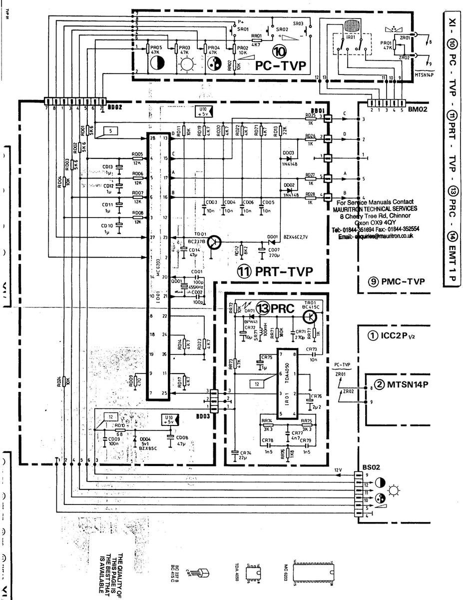
BLOCK DIAGRAMS
10 PC-TVP - 13 PRC - 11 PRT-TVP - 9 PMC-TVP - 12 PAS-TVP
| QELIMITATION DES CIRCUITS | PRINTED CIRCUITS LIMITS |
GEDRÜCKTE SCHALTUNGEN
ABGRENZUNG |
|
|---|---|---|---|
| 23 |
POINTS DE RACCORDEMENT
PAR CONNECTEURS |
CONNECTORS JOINING POINTS |
MEHRFACHSTECKER KONTAKT
PUNKT |
| Ċ | ATTENTE (VEILLE) | STAND-BY | BEREITSCHAFT . |
|
POINT DE RACCORDEMENT PAR
COSSE ENFICHABLE |
PLUG JOINING POINT | STECKER KONTAKT PUNKT | |
| ━+━ | FIL SOUDE SUR CIRCUIT IMPRIME | WIRE SODERING POINT | DRAHT LÖSTELLE |
| _ ( 2) | PREFORMAGE ZZ | SAFETY PREFORMING | Z Z GESTALTET VIDERSTANDE |
| RESISTANCE FUSIBLE | FUSING RESISTOR | SICHERHEIT VIDERSTANDE | |
| +12 V | DEPART TENSION ALIM | FROM POWER SUPPLY | VON NETZ TEIL |
| +12V | TENSION ALIM REÇUE | NACH NETZ TEIL | |
| VOLUME | VOLUME | LAUTSTARKE | |
| $ | LUMIERE | BRIGHTNESS | HELLIGKEIT |
| • | CONTRASTE | CONTRAST | KONTRAST |
| • | SATURATION COULEUR | COLOUR SATURATION | FARBSATTIGUNG |
| →| ←. | VALEUR MOYENNE | BASIC ADJUSTMENT | GRUNDEINSTELLUNG |
| × | SUPPRESSION SON | SOUND PAUSE | TON - STOP |
| TEINTE | HUE | FARBTON | |
| 0 | MARCHE - ARRET | ON - OFF | EIN. AUS |
| Ē | HAUT-PARLEUR . | LOUD. SPEAKER | LAUTSPRECHER |
| Π| PERI TELEVISION | EUROPEAN STANDARD BUSH | EUROPA РNORMBUCHSE |
For Service Manuals Contact MAURITRON TECHNICAL SERVICES 8 Cherry Tree Rd, Chinnor Oxon OX9 4QY Tel: 01844-351694 Fax:- 01844-352554 Email:- enquiries@mauritron.co.uk
BOARD INTERCONNECTIONS
111/.
TVP 01


| CODE | DESCRIPTION | ITEM |
| 196 TX 1847 | PCB, CONTROLS ( PC-TVP ), CPL. | |
| 101 TX 5989 | SWITCH | 1801 |
| 101 TX 2621 | SWITCH | SB01-→03 |
| 207 TX 0670 | POTENTIOMETER 47 k Q A | PR01 |
| 207 TX 1671 | PR02 | |
| 207 TX 2121 | PR03 | |
| 196 TX 1848 |
PCB, REMOTE CONTROL RECEIVER
(PRT-TVP), CPL. |
|
| 276 TX 0554 | IC MC6203 | ID01 |
| 240 TX 0229 | ELECTROLYTIC CAPACITOR 220µF 16V | CD07 |
| 207 TX 1316 | ELECTROLYTIC CAPACITOR 47µF 16V | CD08-14 |
| 207 TX 1075 | ELECTROLYTIC CAPACITOR 1µF 63V | CD10→13 |
| 101 TX 2879 | 6-PIN CONNECTOR | BD01 |
| 101 TX 2872 | 8-PIN CONNECTOR | BD02 |
| 101 TX 3120 | 3-PIN CONNECTOR | 8D03 |
| 273 TX 0194 | DIODE BZX46C2V7 | 0001 |
| 273 TX 0200 | DIODE 1N4148 | 0002-03 |
| 273 TX 0314 | DIODE BZX85C5V1 | 0004 |
| 101 TX 3618 | CERAMIC FILTER | 0001 |
| 101 TX 2141 | IC SOCKET, 2X14 PATHS | |
| 270 TX 0518 | TRANSISTOR BC237B | TD01 |
| 196 TX 1849 |
PCB, STANDARD DISPLAY ( PAS-TVP ),
CPL. |
|
| 102 TX 0966 | SWITCH | SM01 |
| 101 TX 2872 | 8-PIN CONNECTOR | 8M05 |
| 273 TX 1221 | DIODE LED GREEN COV25-5 | DM51-52- |
| 070 72 1000 | 54 | |
| 2/3 1X 1222 | DIODE LED RED CUVZU-4 | UM53 |
| 196 TX 1850 |
PCB, INFRARED RECIEVER ( PRC-TVP ),
CPL. |
|
| 276 TX 0423 | IC TDA4050 | IRO1 |
| 243 TX 0005 | TANTALUM CAPACITOR 10µF 16V | CR72 |
| 207 TX 0404 | TANTALUM CAPACITOR 22µF 16V | CR74 |
| 207 TX 0252 | TANTALUM CAPACITOR 1µF 35V | CR75 |
| 243 TX 0010 | TANTALUM CAPACITOR 2.2µF 16V | CR76 |
| 273 TX 0855 | DIODE BPW41 | DR71 |
| 101 TX 3619 | CHOKE COIL | SR71 |
| 270 TX 1161 | TRANSISTOR BC415C | TR01 |
| 196 TX 2038 | PCB,X-RAY PROTECTION ( PLX01 ), CPL. | |
| 207 TX 1561 | ELECTROLYTIC CAPACITOR 47µF 50V | CL51 |
| 273 TX 0031 | DIODE BZX46C12 | DL40 |
| 207 TX 0340 | ADJUSTABLE POTENTIOMETER 4.7k Ω | PL10 |
| 270 TX 0888 | THYRISTOR BRY55S-30 | DL41 |
| 270 TX 0648 | TRANSISTOR BC5478 | TL10 |
B) EQUIPMENT AND SECURING PARTS
| CODE | DESCRIPTION |
|---|---|
| 101 TX 1855 | PLASTIC CLAMP, SINGLE |
| 705 TX 0546 | PLASTIC CHASSIS |
| 534 TX 0109 | DEFLECTOR |
| 553 TX 0128 | OPTICAL ASSY ( DELTA 3 ) |
| 553 TX 0150 | OPTICAL ASSY ( DELTA 2D ) |
| 580 TX 0426 | LOUDSPEAKER DIAMETER: 10 cm Z:16 Ω |
| 614 TX 2770 | PLASTIC PROTECTION |
| 614 TX 2772 | PLASTIC PROTECTION |
| 102 TX 0972 | PLASTIC SUPPORT |
| CODE | DESCRIPTION |
|---|---|
| 614 TX 2767 | PLASTIC SUPPORT |
| 614 TX 2768 | PLASTIC SUPPORT |
| 614 TX 2769 | PLASTIC SUPPORT |
| 102 TX 0975 | DISTRIBUTOR SUPPORT |
| 750 TX 0049 | CATHODE RAY TUBE, BLUE |
| 750 TX 0047 | CATHODE RAY TUBE, RED |
| 750 TX 0048 | CATHODE RAY TUBE, GREEN |
C) CONTROL ASSEMBLY PARTS
CONTROLS
| CODE | DESCRIPTION | ITEM |
|---|---|---|
| 102 TX 0973 | MAINS SOCKET HOUSING | |
| 101 TX 9016 | SWITCH | 1 |
| 824 TX 0072 | MAINS CABLE | |
| 102 TX 0446 | BNC-SOCKET | |
| 102 TX 0448 | CINCH-SOCKET | |
| 614 TX 2771 | SUPPORT, SOCKETS |
REMOTE CONTROL
| CODE | DESCRIPTION | ITEM |
|---|---|---|
| 925 TX 0276 | REMOTE CONTROL ASSY (EMT1P) | |
| 196 TX 1854 | PCB INFRARED TRANSMITTER, CPL (PEIT1P) | |
| 276 TX 0552 | IC MC14497 | 1711 |
| 240 TX 0105 | ELECTROLYTIC CAPACITOR 1000µF 10V | CT13 |
| 273 TX 0200 | DIODE 1N4148 | DT11 |
| 273 TX 0740 | DIODE INFRA-RED LD271 | DT12→14 |
| 273 TX 1223 | DIODE LED RED LD30A | DT15 |
| 102 TX 0968 | CERAMIC FILTER 500 KHZ | AT11 |
| 101 TX 2376 | BATTERY SNAP, CPL | |
| 101 TX 6436 | IC (2X9 LEADS) SUPPORT | |
| 270 TX 0650 | TRANSISTOR BC548B | BT11 |
| 270 TX 0518 | TRANSISTOR BC237B | BT12 |
D) OUTER PARTS
| CODE | DESCRIPTION |
|---|---|
|
168 TX 1606
166 TX 0539 705 TX 0543 705 TX 0544 715 TX 0910 715 TX 0911 614 TX 2765 705 TX 0542 705 TX 0541 705 TX 0541 705 TX 0545 102 TX 0970 102 TX 0970 102 TX 0971 614 TX 2773 101 TX 3147 166 TX 2121 614 TX 2766 614 TX 2764 |
KNOB, BLACK
KNOB, BLACK RUBBER PROTECTION LENS PROTECTION LOWER CABINET UPPER CABINET CONTROL TRIM RIHGT PLASTIC PANEL PLASTIC PANEL PLASTIC PANEL PLASTIC FOT HANDLE, CPL PROTECTION PUSH BUTTON ON/OFF COVER (UPPER CABINET) PLASTIC COVER |
A) CHASSIS PARTS
-
| L | CODE | DESCRIPTION | ITEM |
|---|---|---|---|
| 796 TX 8528 | CHASSIS ICC2P, CPL. | • | |
| 101 TX 3272 | COIL | LC02 | |
| 101 TX 1900 | COIL | 1003 | |
| 276 TX 0580 | INTEGRATED CIRCUIT TDA3300B | IC01 | |
| ł | 276 TX 0731 | INTEGRATED CIRCUIT TEA1020 | IFO1 |
| l | 276 TX 0746 | INTEGRATED CIRCUIT TDA2593 | ILO1 |
| 276 TX 0171 | INTEGRATED CIRCUIT SFC2812EC OR MC7812CT | IL02 * | |
| 276 TX 0872 | INTEGRATED CIRCUIT TDA2006P | IS02 | |
| l | 276 TX 0314 | INTEGRATED CIRCUIT MC14053 | IX11 |
| 240 TX 0187 | electrolytic capacitor 10µF 25V |
CCU8-24-
64-CL38 |
|
| 1 | 240 TX 0007 | ELECTROLYTIC CAPACITOR 100µF 25V | CC41-CS32 |
| 240 TX 0116 | ELECTROLYTIC CAPACITOR 2.2µF 63V |
CC43-46-
CF03 |
|
| 207 TX 1075 | ELECTROLYTIC CAPACITOR 1µF 63V |
CC51-→53-
68-CS31- CS35-CX04 |
|
| 240 TX 0186 | ELECTROLYTIC CAPACITOR 220µF 25V | CF02-CL02 | |
| I | 240 TX 0183 | ELECTROLYTIC CAPACITOR 47µF 25V | CF04 |
| I | 207 TX 1223 | ELECTROLYTIC CAPACITOR 2200µF 25V | CF07-CL34 |
| 240 TX 0014 | electrolytic capacitor 4.7µF 63V |
C G O 1
CS42CX01 |
|
| I | 207 TX 0188 | POLYPROPYLENE CAPACITOR 4,7nF 1,6kV | CG05 |
| 207 TX 1029 |
NON-POLARIZED ELECTROLYTIC CAPACITOR
22µF 50V |
CLO3 | |
| 207 TX 1233 | METALLIZED POLYESTER CAPACITOR 33nF 10% | CL13 | |
| 240 TX 0119 | ELECTROLYTIC CAPACITOR 10µF 63V | CL22 | |
| 207 TX 0205 | POLYPROPYLENE CAPACITOR 10nF 1,6kV | CL25 | |
| 207 1X 0663 | 250V | CL27 | |
| 241 TX 0001 | ELECTROLYTIC CAPACITOR 4.7µF 275V | | CL30 | |
| 207 TX 1506 | LLECTROLYTIC CAPACITOR 150µF 160V | CP33 | |
| 240 TX 0181 | ELLIHULTHU CAPACITUH 4/UMF 40V | 1000 | |
| 207 1X 0934 | ELECTROLYTIC CAPACITOR 22.45 254 | 0000 | |
| 102 TY DOGO | RPIN CONNECTOR | BC03 | |
| 101 TX 6745 | 7-PIN CONNECTOR | BLO1 | |
| 101 TX 6747 | 13-PIN CONNECTOR | BS02 | |
| 273 TX 0200 | DIODE 1N4148 |
D C 1 0
30→32- 48-49- 51-81- 82-0F02- 0L02-32- 0S17-0X01 |
|
| 273 TX 0025 | DIODE 1N4001 | DF01-DP38 | |
| 273 TX 0650 | DIODE H572-1 OR PLR2OT | DG01-02 | |
| 273 TX 0033 | DIODE BA157 | DLO1 | |
| 273 TX 0552 | DIODE BA158 | DL05 | |
| 273 TX 0862 | DIODE MR854 | DL10 | |
| 273 TX 0089 | DIODE BZX46C4V7 | DP39 | |
| 273 TX 0500 | DIODE BZX46C9V1 | DP41 | |
| 273 TX 0866 | DIODE BZX46C3V9 | 001 | |
| 101 TX 6750 | DELAY LINE 390NS | 1004 | |
| 101 TX 6748 | DELAY LINE 64MS | ||
| 238 1X 0021 | PCPE | ||
| 20/ 1X 16/0 | AD HISTADLE PUTENTIONETER TUU KS | PC03 | |
| 20/18/034/ | PC02 | ||
| 207 1X 0122 | AD INSTABLE POTENTIONETED 224 36 | PI 01.02 | |
| 101 TY 5642 | SCART PERLTY SOCKET | RX10 | |
| 101 17 0045 | CRYSTAL & A339818mH7 | 0003 | |
| CODE | DESCRIPTION | ITEM |
| 102 TX 0960 | CRYSTAL '3.579545mHZ | 0C04 |
| 207 TX 2111 | FILM BESISTOR 464k Q 1% 0.25W | 8F07 |
| 207 TX 0192 | WIRE RESISTOR 1 Q 5% 2W | RF16 |
| 207 TX 1858 | FILM RESISTOR 357 k Ω 1% 0.25W | RF22 |
| 207 TX 2113 | NTC THERMISTOR 470 Q 0.50W | RG03 |
| 207 TX 1517 | FILM RESISTOR 22 Q 5% 0.25W | RG06 |
| 207 TY 2114 | LAYER RESISTOR 33 O 5% 0.50W | BL33 |
| 207 TX 1510 | FILM RESISTOR 0.1 Q 5% 0.40W | RL36-45 |
| 203 TX 0006 | LAYER RESISTOR 39 Q 5% 4W | RL40 |
| 207 TX 1511 | EILM RESISTOR 1 Q 5% 0.30W | R149 |
| 207 TX 2115 | LAYER RESISTOR 0.58 Q 5% 0.50W | BL58 |
| 101 TX 1792 | CHOKE | 1001-18- |
| ···· | 1101 | |
| 101 TX 6751 | СНОКЕ | LC40 |
| 101 TX 2374 | CHOKE 10mH | LFO1 |
| 101 TX 3081 | СНОКЕ | LF02-LLO2 |
| 101 TX 4939 | СНОКЕ | lgo1 |
| 101 TX 4929 | CHOKE COIL | lp03-04 |
| 102 TX 0959 | LINEARITY CHOKE | LL06 |
| 101 TX 4971 | 2X20-PATH IC SOCKET | |
| 423 TX 0226 | POWER TRANSFORMER | UGO1 |
| 423 TX 0174 | POWER TRANSFORMER | ULO1 |
| 534 TX 0108 | VHT TRANSFORMER | ULO2 |
| 270 TX 0649 | TRANSISTOR BC557B | TC01-TX02 |
| 270 TX 1021 | TRANSISTOR BF422 | TG01 |
| 270 TX 1170 | TRANSISTOR BF760 . | TGO2 |
| 270 TX 1283 | TRANSISTOR BC639 | TLO1 |
| 270 TX 1235 | TRANSISTOR BU500D OR BU208D OR S2818 | T1 04 |
| 270 TX 0544 | TRANSISTOR BC337-25 | TP32 |
| 270 TX 0726 | TRANSISTOR BC237C | TS30 |
| 270 TX 0518 | TRANSISTOR BC2378 | TX01-03 |
| 534 TX 0110 | TRIPLER, CPL ( WITH FOCUS DIVIDER ) | |
| 596 TX 1141 |
PCB, PAL/SECAM/NTSC SWITCHING
(MTSN14P), CPL. |
|
| 311 TX 0044 | COIL | 1072 |
| 101 TX 1900 | COL | LC73 |
| 276 TX 1038 | INTEGRATED CIRCUIT TDA3030B | 1002 |
| 240 TX 0164 | ELECTROLYTIC CAPACITOR 10µF 16V | CC71-86 |
| 101 TX 6758 | 11-PIN CONNECTOR (CONNECTION | |
| ICC2P/MTSN14P } | BC01-02 | |
| 273 TX 0200 | DIODE 1N4148 | DC71-72- |
| 207 TV 1871 | AD INSTADIC DOTENTIONETED 104 O | DR72 |
|
20/ 18 10/1
207 דע המזיד |
PND1 | |
| 101 TV 03// | CHOKE | 1071 |
| 101 IA 0/05 | IN SOCKET 2X14 PATHS | |
| 270 TX 0517 | TRANSISTOR BC307B | TC71-73- |
| ATA TH AFIE | TO AMOINTON DOGOTO | |
| 270 IX 0518 | THANSISTUR BUZ378 | TN01→03- |
|
05→07-
09-→11 |
||
| 798 TY 0570 | ļ | |
| 147 TV 0017 | DOLYDODDY ENE CADACITOD DOLE EN 144 | 001 |
| 24/ 1X 001/ | FULTENUTLENE GAPACITUR JJOR DA IKV | CPUI |
| 240 17 0100 | CEUS | |
|
240 IX 0100
240 TV 0014 |
FIETROLYTIC CAPACITOR A 7.15 62V | CP10 |
| 240 1A 0014 | CP13 | |
| 240 1 100 | CP15.10 | |
| 240 14 0003 | LEEVINGEING UNINGIUN T/UPLE 201 | 20 |
| 207 TX 1506 | ELECTROLYTIC CAPACITOR 150µF 160V | CP17 |
PARTS LISTS
TVP 01
| CODE | DESCRIPTION | TTEM |
| 240 TX 0008 | ELECTROLYTIC CAPACITOR 10011F 40V | CP18 |
| 207 TX 0695 | ELECTROLYTIC CAPACITOR 2204E 385V | CP21 |
| 249 TX 0030 | CERAMIC CAPACITOR INF INV | CP22-23 |
| 207 TX 1236 | METALLIZED POLYESTER CAPACITOR 0.14E 1KV | CP24-29 |
| 207 TX 0892 | CERAMIC CAPACITOR 3.3nF 400V | CP25-26 |
| 101 TX 6745 | 7-PIN CONNECTOR | BP02 |
| 273 TX 0538 | DIODE BY299 | DP01-18- |
| 273 TY 0205 | DIODE PLR2T |
19-21
DP02-03- |
| 210 17 0200 | 05-11- | |
| 15-16- | ||
| 273 TX 0200 | DIODE 1N4148 | DP04-07- |
| 08-12- | ||
| 272 TV 0500 | 20 | |
| 273 1X 0500 | npna | |
| 273 17 0020 | ||
| 273 17 0031 | DP14 | |
| 273 1X 0037 | DIODE BA167 | DP17.21. |
| 2/3 14 0033 | 32 | |
| 273 TX 0675 | DIODE MR856RL | DP22-→25 |
| 273 TX 0470 | DIODE BY255 | DP26-→29 |
| 101 TX 2734 | GLASS FUSE 1.6A | FP01 |
| 291 TX 0011 | TIME-LAG GLASS FUSE 2.5A | FP02 |
| 238 TX 0065 | ADJUSTABLE POTENTIOMETER 2,2 k Ω | PPOT |
| 238 TX 0039 | PP02 | |
| 207 1X 0377 | PPU3 | |
| 207 1X 0642 | WIRE RESISTUR 4/U $2 TU% TW | W-U3 |
| 207 1X 2116 | WINE RESISTUR 2/12 5% /W | HPU8 |
| 207 1X 0040 | WIRE RESISTUR 1,5 12 10% OW |
8P20-50-
51 |
| 220 TX 0066 | wire resistor 0,82 Ω 10% 4,5w | RP23 |
| 207 TX 2117 | Layer Resistor 0,15 Ω 10% 0,40W | RP44-48 |
| 207 TX 1510 | Film resistor 0.1 Ω 5% 0.40W | RP47-49- |
| 207 TX 2118 | LAYER RESISTOR 10 MOHM 10% 1W | RP58 |
| 101 TX 3081 | СНОКЕ | LP01 |
| 423 TX 0095 | FILTER CHOKE | LPO2 |
| 116 TX 0007 | FUSE-HOLDER | |
| 270 TX 0888 | THYRISTOR BRY55S-30 | TP09 |
| 433 TX 0383 | POWER TRANSFORMER | UP01 |
| 270 TX 1020 | TRANSISTOR BUY69A | TP01 |
| 270 TX 0690 | TRANSISTOR BC327/25 | TP02-05- |
| 270 TX 0726 | TRANSISTOR BC237C | TP03 |
| 270 TX 0518 | TRANSISTOR BC237B | TP04-08 |
| 270 TX 0517 | TRANSISTOR BC307B | TP07 |
| 796 TX 0530 | PCB CONVERGENCES ( PC01 ), CPL. | |
| 276 TX 1046 | IC TI 431C | 0001 |
| 276 TX 1047 | INTEGRATED CIRCUIT TLOB2CP OR MC34002P | 1001>06- |
| 240 TY 0197 | ||
| 240 17 0107 | 09 | |
| 207 TX 1253 | ELECTROLYTIC CAPACITOR 1000µF 25V | CQ02-15 |
| 240 TX 0007 | ELECTROLYTIC CAPACITOR 100µF 25V | C005 |
| 101 TX 3304 | 3-PIN CONNECTOR | BQO1 |
| 101 TX 3305 | 4-PIN CONNECTOR | B003 |
| 102 TX 0961 | 8-PIN CONNECTOR | 8004 |
| 101 TX 2873 | 5-PIN CONNECTOR | 8005→07 |
| 273 TX 0200 | DIODE 1N4148 | D002 |
| 207 TX 0122 | ADJUSTABLE POTENTIOMETER 22k Q | P007+33 |
| 207 TX 2119 | LAYER RESISTOR 2,4 k \Q 1% 0,25W | R004 |
| 207 TX 1577 | LAYER RESISTOR 22 Ω 0.5W | R0085-086- |
| 101-102- | ||
| 109-110- | ||
| • | 126-127 |
| CODE | DESCRIPTION | ITEM |
|---|---|---|
| 101 TV 4000 | 100102 | |
|
101 1X 4929
270 TV 1491 |
1001-02
1001-503 |
|
| 270 TX 1401 | TRANSISTOR RE7464 | T001>03 |
| 270 TX 1482 | TRANSISTOR BI239 | T005-07- |
| 09-11- | ||
| 13-15 | ||
| 270 IX 1483 | TRANSISTUR BUZ4U | 10.12- |
| - | 14-16 | |
| 1 |
PCB, STATIC CUNVERGENCE (PFS-
TVP) including : |
|
| 506 TY 1402 | ENCLIS AD HISTMENT ASSY | |
| 207 TX 1670 | AD HISTARI F POTENTIOMETER 100 k Q | 2001>06 |
| 196 TX 1843 | PCB VIDEO AMPLIFIER RED ( PAV-R ) CPL | |
| 196 TX 1844 | PCB VIDEO AMPLIFIER GREEN ( PAV-V ) | |
| 196 TX 1845 | PCB VIDEO AMPLIFIER BLUE (PAV-B) | |
| 240 TX 0014 | ELECTROLYTIC CAPACITOR 4.7µF 63V | CV03 |
| 207 TX 0653 | CERAMIC CAPACITOR 4.7nF 3kV | CV04 |
| 273 IX 0200 | DIODE 1N4148 | DVU3-04 |
| 2/3 1X U1/1 | UNUE IN 4004 | UVU5 |
|
101 1A 4832
207 TY 0377 |
||
| 207 TX 1226 | ADJUSTABLE FOTENTIOMETER 1 MOHM | PV02 |
| 207 TX 1468 | FILM RESISTOR 1k Q 5% 0.25W | RV10 |
| 102 TX 0963 | SUPPORT CATHODE RAY TUBE | |
| 270 TX 0822 | TRANSISTOR BF758 | TV01 |
| 270 TX 1021 | TRANSISTOR BF422 | TV02 |
| 270 TX 1172 | TRANSISTOR BF423 | TV03 |
| 196 TX 1846 | INTERMEDIATE PCB, CPL. ( PIR1 ) | |
| 241 TX 0001 | ELECTROLYTIC CAPACITOR 474E 275V | CB01 |
| 101 TX 6745 | 7-PIN CONNECTOR | B008→10 |
| 500 TV 1400 | ||
| 209 TX 1492 | PUCUS ALUUSIMENI ASSY | 0105 .07 |
| 200 TX 2004 | SPECIAL RESISTOR 56 MOHM | RI 70 |
| 596 TX 1142 | PCB, PATTERN AND SWITCHING ( PMC- | |
| 276 TX 1048 | INTEGRATED CIRCUIT SN74LSDON | IM01-02 |
| 276 TX 1049 | IC SN74LS03 | IM03 |
| 276 TX 1050 | IC MM5322N | IM04 |
| 276 TX 0314 | INTEGRATED CIRCUIT MC14053 | IM05 |
| 276 TX 0170 | INTEGRATED CIRCUIT TDA1048 | IM06 |
| 240 TX 0183 | ELECTROLYTIC CAPACITOR 47µF 25V | CM01-06- |
| 207 TX 1075 | ELECTROLYTIC CAPACITOR 114F 63V | CM09 |
| 240 TX 0187 | ELECTROLYTIC CAPACITOR 10µF 25V | CM10-11 |
| 102 TX 0967 | 6-PIN CONNECTOR | BIO1 |
| 101 TX 3305 | 4-PIN CONNECTOR | BM01 |
| 101 TX 2873 | 5-PIN CONNECTOR | BM02 |
| 101 1X 312/ | ID-PIN CONNECTOR | BM03 |
|
101 1X 0/00
273 TY 0314 |
0501
DM01 |
|
| 273 TX 0314 | DIODE BZX46C7V5 | DM01 |
| 273 TX 0200 | DIODE 1N4148 | DM03 |
| 102 TX 0965 | CERAMIC FILTER 378 KHZ | QM01 |
| 207 TX 0419 | FILM RESISTOR 4.75k Ω 1% 0.25W | RM31 |
| 207 TX 0420 | FILM RESISTOR 15.4k Ω 1% 0.25W | RM34 |
| 101 TX 0695 | IC SOCKET 2X7 PATHS | |
| 101 TX 2704 | I'L' SOCKET 2X8 PATHS | - |
| 270 IX 0517 | TRANSISTOR DC327 10 | IM01-03 |
|
270 TX 0522
270 TY 0510 |
TMUZ | |
| 21014 0010 | | 110/10/07 DU20/D | | €MU4->U/ |
PARTS LIST
TVP 01
1
HOUSING, REMOTE CONTROL
| CODE | DESCRIPTION |
|---|---|
|
600 TX 0445
600 TX 0446 |
LOWER CABINET
UPPER CABINET, CPL |
| 152 TX 2971 | BATTERY LID COVER |
| 102 TX 0969 | FILTER, INFRARED |
E) ACCESSORIES
| CODE | DESCRIPTION |
|---|---|
| 925 TX 0277 | CONVERGENCE CONTROL CARD |
| 758 TX 1429 | PACKAGING,CPL |
| 966 TX 0370 | SERVICE MANUAL TVP01 |
| 966 TX 0275 | OPERATING INSTRUCTIONS TVP01 |
For Service Manuals Contact MAURITRON TECHNICAL SERVICES 8 Cherry Tree Rd, Chinnor Oxon OX9 4QY Tel:- 01844-351694 Fax:- 01844-352554 Email:- enquiries@mauritron.co.uk
TVP 01


THE QUALITY OF THIS PAGE IS THIS BEST THAT THE BEST THAT IS AVAILABLE
For Service Manuals Contact MAURITRON TECHNICAL SERVICES 8 Cherry Tree Rd, Chinnor Oxon OX9 4QY Tel:- 01844-351694 Fax:- 01844-352554 Email:- enquiries@mauritron.co.uk

ali ana ina ina kana ang


a:-*


-

11111
10 411


 Loading...