

Page 1
Power
E
th
ern
et
W
LA
N
Plug-in
ISDN
Internet
DS
L
VLAN Configuration Guide
R7.4 and higher
Thomson Gateway
Page 2

Page 3

Thomson Gateway
VLAN Configuration Guide
R7.4 and higher
Page 4

Copyright
Copyright ©1999-2008 Thomson. All rights reserved.
Distribution and copying of this document, use and communication of its contents is not permitted without written authorization
from Thomson. The content of this document is furnished for informational use only, may be subject to change without notice,
and should not be construed as a commitment by Thomson. Thomson assumes no responsibility or liability for any errors or
inaccuracies that may appear in this document.
Thomson Telecom Belgium
Prins Boudewijnlaan, 47
B-2650 Edegem
Belgium
http://www.thomson-broadband.com
Trademarks
The following trademarks may be used in this document:
DECT is a trademark of ETSI.
Bluetooth® word mark and logos are owned by the Bluetooth SIG, Inc.
Ethernet™ is a trademark of Xerox Corporation.
Wi-Fi® and the Wi-Fi logo are registered trademarks of the Wi-Fi Alliance. "Wi-Fi CERTIFIED", "Wi-Fi ZONE", "Wi-Fi Alli-
ance", their respective logos and "Wi-Fi Protected Access" are trademarks of the Wi-Fi Alliance.
UPnP™ is a certification mark of the UPnP™ Implementers Corporation.
Microsoft®, MS-DOS®, Windows®, Windows NT® and Windows Vista® are either registered trademarks or trademarks
of Microsoft Corporation in the United States and/or other countries.
Apple® and Mac OS® are registered trademarks of Apple Computer, Incorporated, registered in the United States and
other countries.
UNIX® is a registered trademark of UNIX System Laboratories, Incorporated.
Adobe®, the Adobe logo, Acrobat and Acrobat Reader are trademarks or registered trademarks of Adobe Systems, Incor-
porated, registered in the United States and/or other countries.
Other brands and product names may be trademarks or registered trademarks of their respective holders.
Document Information
Status: v1.0 (March 2008)
Reference: E-DOC-CTC-20080229-0001
Short Title: Config Guide: VLAN R7.4 and higher
Page 5

E-DOC-CTC-20080229-0001 v1.0
i
Contents
About this VLAN Configuration Guide ..................................... 1
1 Introduction..................................................................................3
2 VLAN Overview ........................................................................... 5
3 Creating VLANs on the Thomson Gateway.............................. 9
4 Ethernet Bridge and VLANs......................................................11
4.1 VLAN Learning Constraints........................................................................... 12
4.2 Static Entries with VLANs ............................................................................ 14
4.3 VLAN Awareness .......................................................................................... 16
4.4 Port VLAN Membership ................................................................................ 17
4.5 Optional Incoming Traffic Validation............................................................ 20
4.6 Dynamic VLAN Membership ......................................................................... 22
4.7 Unknown VID Policy ..................................................................................... 25
4.8 Extra Tagging (Stacked VLANs) .................................................................... 28
5 Logical Ethernet Interfaces and VLANs................................... 33
5.1 WAN-side VLAN Tagging............................................................................... 34
5.2 VLAN Routing on the Thomson Gateway...................................................... 35
Page 6

E-DOC-CTC-20080229-0001 v1.0
ii
Contents
Page 7

E-DOC-CTC-20080229-0001 v1.0
1
About this VLAN Configuration Guide
About this VLAN Configuration Guide
Used Symbols
Terminology
Generally, the Thomson Gateway356 will be referred to as Wireless USB Adaptor in this VLAN Configuration
Guide.
Typographical Conventions
Following typographical convention is used throughout this manual:
Sample text indicates a hyperlink to a Web site.
Example: For more information, visit us at www.thomson-broadband.com
.
Sample text indicates an internal cross-reference.
Example: If you want to know more about guide, see “1 Introduction” on page 7”.
Sample text indicates an important content-related word.
Example: To enter the network, you must authenticate yourself.
Sample text indicates a GUI element (commands on menus and buttons, dialog box elements, file
names, paths and folders).
Example: On the File menu, click Open to open a file.
Documentation and software updates
Thomson continuously develops new solutions, but is also committed to improving its existing products.
For more information on Thomson's latest technological innovations, documents and software releases, visit
us at http://www.thomson-broadband.com
.
A note provides additional information about a topic.
A caution warns you about potential problems or specific precautions that need to be taken.
Page 8
E-DOC-CTC-20080229-0001 v1.0
2
About this VLAN Con
figuration Guide
Overview
First, this VLAN Configuration Guide shortly lists the VLAN features of the Thomson Gateway and the
relevant standards. Some background information on several VLAN-related concepts is also provided. Next,
this document describes the configuration of each VLAN feature on the Thomson Gateway in detail. CLI
(Command Line Interface) commands are used for the configuration.
This document is structured as follows:
Topi c Page
“1 Introduction” 3
“2 VLAN Overview” 5
“3 Creating VLANs on the Thomson Gateway” 9
“4 Ethernet Bridge and VLANs” 11
“5 Logical Ethernet Interfaces and VLANs” 33
Page 9

E-DOC-CTC-20080229-0001 v1.0
3
1| Introduction
1 Introduction
Introduction
Virtual Local Area Networks, commonly known as VLANs, are the subject of this document. In this chapter,
we shortly list the VLAN features that are supported by the Thomson Gateway, the relevant standards and
related documents.
Supported VLAN features
Thomson Gateway devices support following VLAN features:
Creation of VLANs on the Thomson Gateway
VLAN features of the Ethernet bridge
VLAN learning constraints for dynamic entries
Creation of static entries with VLANs
VLAN awareness of the bridge
Tagged and untagged VLAN membership of bridge ports
Port VID of a bridge port
Acceptance of only VLAN-tagged frames
Ingress filtering of VLAN-tagged frames
Dynamic VLAN membership
Unknown VID policy
Extra tagging (stacked VLANs)
VLAN features of the logical Ethernet interfaces
WAN-side VLAN tagging
Support of VLAN routing on the Thomson Gateway
Standards compliancy
Thomson Gateway devices are compliant with following standards, which are relevant to Ethernet, Ethernet
bridging, VLAN bridging, VLAN user priorities and stacked VLANs:
IEEE Std 802.3 - 2000: Part 3: Carrier sense multiple access with collision detection (CSMA/CD) access
method and physical layer specifications.
IEEE Std 802.1D - 2004: IEEE standard for local and metropolitan area networks - Media Access Control
(MAC) bridges.
IEEE Std 802.1Q - 1998: IEEE standard for local and metropolitan area networks - Virtual bridged local
area networks.
IEEE Std 802.1p: Traffic Class Expediting and Dynamic Multicast Filtering. This standard is merged into
802.1D-2004.
IEEE Std 802.1ad - 2005: IEEE standard for local and metropolitan area networks - Virtual bridged local
area networks - Amendment 4: Provider bridges.
Related documents
Other Layer 2 related features, such as Ethernet and Ethernet QoS, are described in other documents. See the
“Ethernet Configuration Guide” and the “Ethernet QoS Configuration Guide” for more information.
Page 10

E-DOC-CTC-20080229-0001 v1.0
4
1| Introduction
Page 11
E-DOC-CTC-20080229-0001 v1.0
5
2| VLAN Overview
2 VLAN Overview
What is a VLAN?
A VLAN is a Layer 2 method of creating independent logical networks within a single physical network. Hosts
in the same VLAN behave as if they are connected to the same LAN segment, even though they may be
physically connected to different LAN segments.
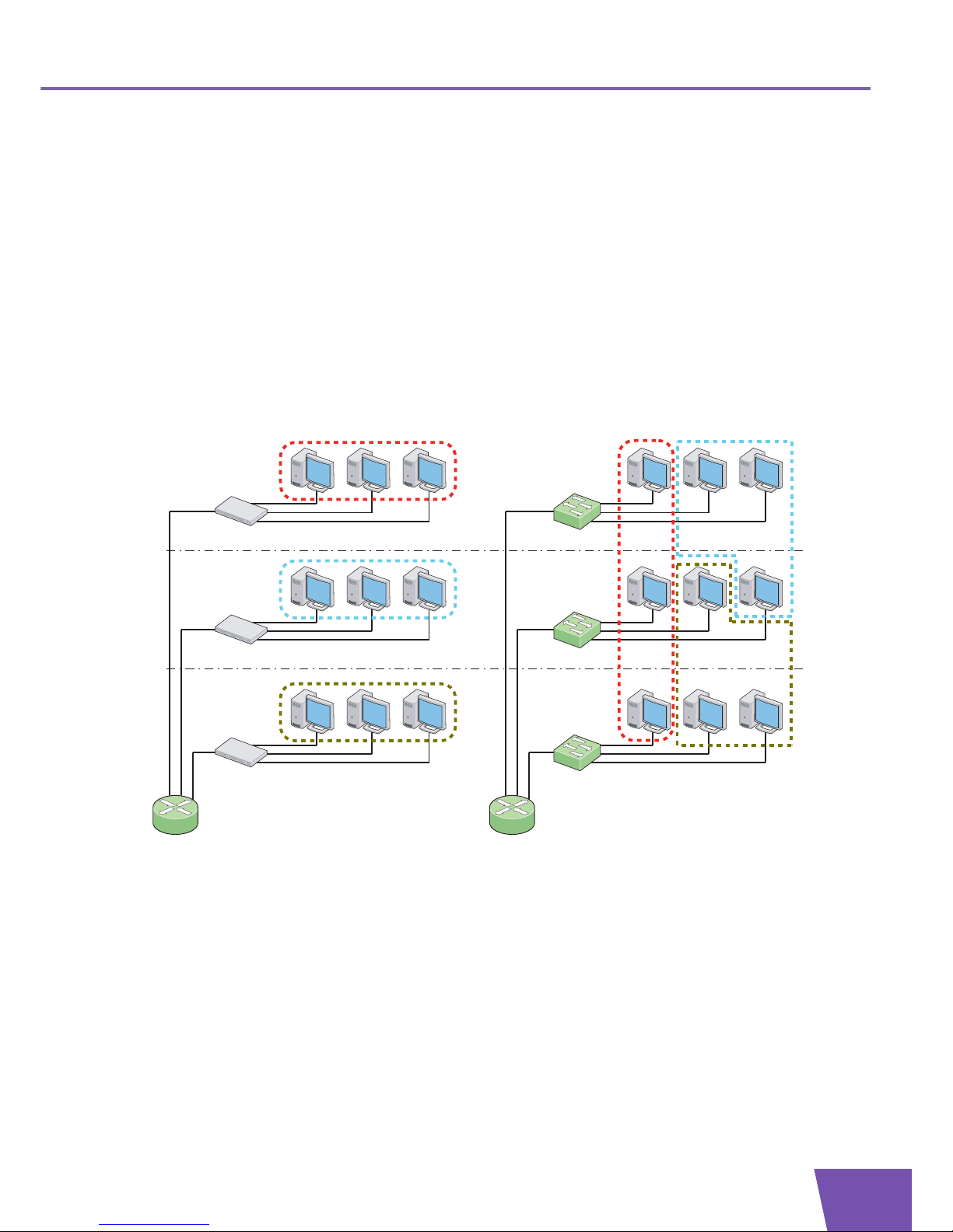
The primary use of VLANs is to split large switched networks, which are large broadcast domains. While
traditional LAN segmentation adds routers to the network to split a broadcast domain, VLAN segmentation
adds VLAN-aware switches. Routers are only needed to communicate between two VLANs.
Following illustration shows the difference between traditional physical LAN segmentation and logical VLAN
segmentation:
Advantages of using VLANs
The use of VLANs is very popular in today’s networks, because VLANs offer several advantages:
Increased performance:
VLANs increase the number of broadcast domains but reduce the size of each broadcast domain. As
this limits broadcast storms, multicast traffic, chatty protocols and so on, overall network traffic is
reduced.
VLAN-aware switches add no substantial latency compared to routers, as the amount of routing
(Layer 3 forwarding) is reduced.
Snooping is limited, which increases the network security.
Router
VLAN1 VLAN2
VLAN3
VLAN Switch
VLAN Switch
VLAN Switch
LAN3
Hub
Router
LAN1
Hub
LAN2
Hub
Traditional LAN segmentation VLAN segmentation
Page 12
E-DOC-CTC-20080229-0001 v1.0
6
2| VLAN Overview
Topological independence: the use of VLANs allows non-physical grouping of nodes that share similar
resources. This results in the creation of logical networks, independent of the physical location of the
involved nodes. Hardware requirements are reduced, as networks can be separated logically instead of
physically.
Ease of administration: the management efforts to create (logical) networks are reduced:
Nodes can easily change their VLAN membership.
Network topology changes, for example a host moving to another location, no longer require
hardware changes but can be done via software.
Cost-effectiveness is improved: less routers, which are costly, are needed and VLAN-aware switches are
used instead. Routers are only needed to communicate between two VLANs.
Additional features: the VLAN user priority allows Layer 2 traffic separation.
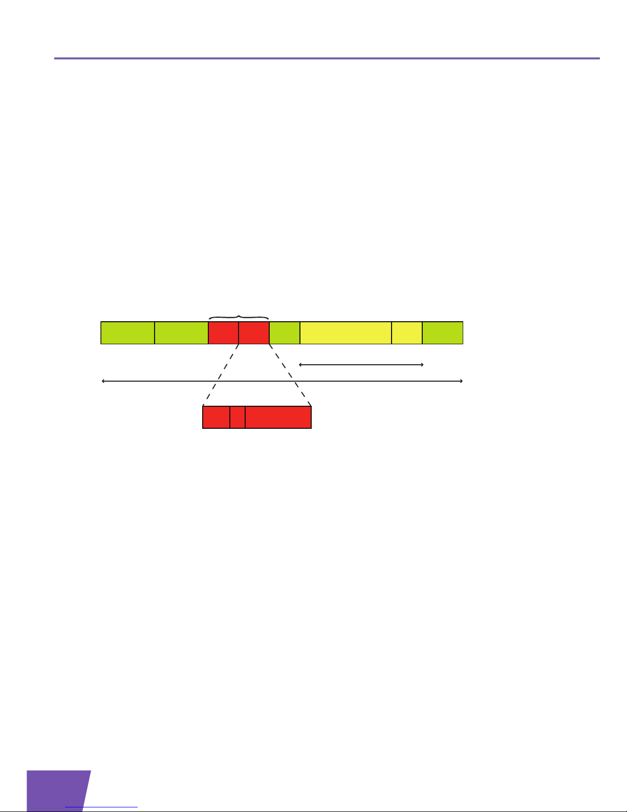
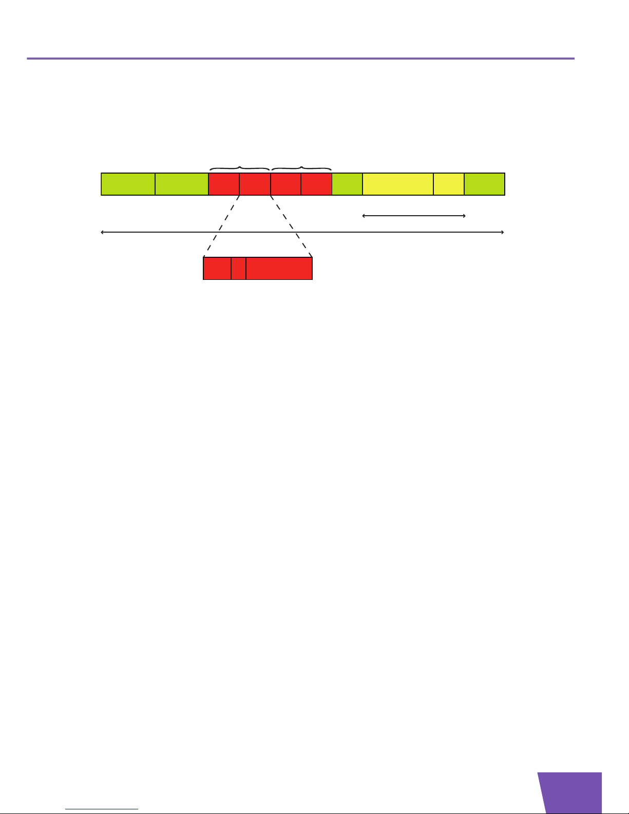
VLAN-tagged frame format
In order to support VLANs, the Ethernet frame format is extended with a VLAN tag, indicated in red in the
following illustration:
A VLAN tag consists of following fields:
Tag Protocol Identifier (TPID): this field is located at the same place as the Length/Type field of untagged
frames. The value of the field is always equal to 0x8100, which indicates that the frame is tagged and that
the original Length/Type field is located after the VLAN tag.
Tag Control Information (TCI):
User Priority Field: this field indicates the 802.1p user priority.
Canonical Format Indicator (CFI)
VLAN Identifier (VID): this field identifies the VLAN to which the frame belongs.
Destination
MAC Address
Source
MAC Address
Length/
Type
TPID TCI
FCS
662 422
PadData/LLC
0 .. 1500 46 .. 0 bytes
Min. 46 bytes - Max. 1500 bytes
Min. 68 bytes - Max. 1522 bytes
Priority CFI VID
3 1 12 bits
VLAN tag
Page 13
E-DOC-CTC-20080229-0001 v1.0
7
2| VLAN Overview
Stacked VLAN frame format
VLAN stacking means that a frame contains two VLAN tags. An example of a stacked VLAN frame format is
shown in the following illustration:
An S-tag can be distinguished from a C-tag as follows:
The value of the TPID field of an S-tag is set to 0x88a8.
An S-tag contains a DEI (Drop Eligible Indicator) field instead of a CFI field.
Destination
MAC Address
Source
MAC Address
Length/
Type
TPID TCI
FCS
662 422
PadData/LLC
0 .. 1500 46 .. 0 bytes
Min. 46 bytes - Max. 1500 bytes
Min. 72 bytes - Max. 1526 bytes
TPID TCI
22
Customer
VLAN tag
= C-tag
Service Provider
VLAN tag
= S-tag
Priority DEI VID
3 1 12 bits
Page 14

E-DOC-CTC-20080229-0001 v1.0
8
2| VLAN Overview
Page 15

E-DOC-CTC-20080229-0001 v1.0
9
3| Creating VLANs on the Thomson Gateway
3 Creating VLANs on the Thomson Gateway
Introduction
This chapter describes the creation of new VLANs on the Thomson Gateway. As soon as a VLAN is created, it
can be used for:
VLAN bridging by the Ethernet bridge.
WAN-side VLAN tagging by logical Ethernet interfaces.
VLAN routing.
The CLI commands explained in this chapter belong to the command group
:eth vlan.
Creating a new VLAN
To create a new VLAN, use the command :eth vlan add.
Two parameters must be specified:
Name: the name of the new VLAN.
Vid (VLAN identifier): the VID of the new VLAN.
This VID corresponds to the value of the VID field of VLAN-tagged frames that belong to this VLAN. As
this VID field has a size of 12 bits, the VID can be a number within the range from 0 through 4095.
However, following VIDs are reserved and can not be used to create a new VLAN:
0: this value indicates that the VLAN tag contains only user priority information and no VID.
1: this value indicates the default VID. This value is already in use by the default VLAN on the bridge.
4095: this value is reserved.
Optionally, following parameter can be specified:
Addrule: this parameter indicates whether the default VLAN learning constraint is used. If the parameter
is not specified, the parameter is enabled.
If the parameter is enabled, the default VLAN learning constraint is used. This means that Shared
VLAN Learning (SVL) is being used between the new VLAN and the default VLAN.
If the parameter is disabled, a separate filtering database is created for the new VLAN and
Independent VLAN Learning (IVL) is being used implicitly.
For example, to create a data, video and voice VLAN, execute following commands:
It is recommended to disable this parameter when creating a new VLAN. In this case, the same
MAC address can be used in different VLANs. No MAC address conflicts occur when different
VLANs are connected to the same device (for example a router at the WAN side).
For more information on the configuration of VLAN learning constraints, see “4.1 VLAN
Learning Constraints” on page 12.
=>:eth vlan add name=data vid=2
=>:eth vlan add name=video vid=3 addrule=enabled
=>:eth vlan add name=voice vid=4 addrule=disabled
Page 16

E-DOC-CTC-20080229-0001 v1.0
10
3| Creating VLANs o
n the Thomson Gateway
Listing all VLANs
To list all VLANs that were created in the previous example, execute following command:
Deleting a VLAN
To delete a specific VLAN, use the command :eth vlan delete.
One parameter must be specified:
Name: the name of the VLAN to be deleted.
For example, to delete the voice VLAN, execute following command:
Flushing all VLANs
To delete all VLANs at once, execute following command:
=>:eth vlan list
Vid Name
--- ---1 default
2 data
3 video
4 voice
The number of active VLANs is the number of VLANs that are in use at a certain moment. The
maximum number of active VLANs that the bridge can support at any time is 15, including the
VLANs that are already created by default.
=>:eth vlan delete name=voice
=>:eth vlan list
Vid Name
--- ---1 default
2 data
3 video
You cannot delete the default VLAN (VID=1).
Even if one or more bridge ports are member of the deleted VLAN, the VLAN is deleted without
warning. Each affected bridge port becomes untagged member of the default VLAN.
=>:eth vlan flush
=>:eth vlan list
Vid Name
--- ---1 default
You cannot flush the default VLAN (VID=1).
Even if one or more bridge ports are member of the flushed VLANs, the VLANs are deleted without
warning. All bridge ports become untagged members of the default VLAN.
Page 17

E-DOC-CTC-20080229-0001 v1.0
11
4| Ethernet Bridge and VLANs
4 Ethernet Bridge and VLANs
Introduction
This chapter describes the VLAN features of the Ethernet bridge in detail. These VLAN features can be
grouped as follows:
Ethernet bridge:
The learning process is extended with the use of VLAN learning constraints.
Static entries can be configured per VLAN or for all VLANs.
VLAN awareness of the bridge.
Ethernet bridge ports:
Tagged and untagged VLAN membership of the bridge ports.
Control of unexpected incoming frames on a bridge port.
Advanced VLAN features:
Dynamic VLAN membership.
Unknown VID policy.
Extra tagging.
Overview
This chapter is structured as follows:
Topi c Page
“4.1 VLAN Learning Constraints” 12
“4.2 Static Entries with VLANs” 14
“4.3 VLAN Awareness” 16
“4.4 Port VLAN Membership” 17
“4.5 Optional Incoming Traffic Validation” 20
“4.6 Dynamic VLAN Membership” 22
“4.7 Unknown VID Policy” 25
“4.8 Extra Tagging (Stacked VLANs)” 28
Page 18

E-DOC-CTC-20080229-0001 v1.0
12
4| Ethernet Bridge a
nd VLANs
4.1 VLAN Learning Constraints
Introduction
The supported self-learning VLAN bridge functionality operates according to IEEE 802.1Q. This learning
process creates the dynamic entries in the filtering data base(s) of the Ethernet bridge.
The CLI commands explained in this section belong to the command group
:eth bridge rule.
Multiple filtering data bases
The Ethernet bridge supports multiple filtering data bases. Each filtering data base can be shared by multiple
VLANs.
VLAN learning constraints
The VLAN learning constraints used by the learning process determine which dynamic entries are created in
which filtering data bases.
Following VLAN learning constraints exist:
Shared VLAN Learning (SVL): only one filtering data base is supported, shared by all VLANs. This means
that if an individual MAC address is learned in one VLAN, that learned information can be used in
forwarding decisions taken for that address by all other VLANs.
In this case, only one entry for a specific MAC address can exist. The same MAC address can not be
forwarded differently in different VLANs.
Independent VLAN Learning (IVL): multiple filtering data bases are supported and each data base is used
by only one VLAN. This means that if an individual MAC address is learned in one VLAN, that learned
information is only used in forwarding decisions taken for that address by that VLAN.
In this case, the same MAC address can be used in different VLANs, as each filtering data base can
contain an entry for that MAC address. This way, the Thomson Gateway can be connected to the same
device via different connections.
Shared VLAN Learning/Independent VLAN Learning (SVL/IVL): this is a combination of SVL and IVL.
Creating a new VLAN learning constraint
To create a new VLAN learning constraint, use the command :eth bridge rule add.
Following two parameters must be specified:
Type : the type of the VLAN learning constraint. This type can be set to:
Shared
Independent
Vlan: the VLAN to which the constraint belongs.
Depending on the selected type, one of the following parameters must be specified:
Vlan2: if the type is set to shared, this parameter indicates a second VLAN. As a result, Shared VLAN
Learning is used between the VLANs identified by the pair of VLANs (Vlan and Vlan2).
Isi: if the type is set to independent, this parameter indicates the Independent Set Identifier (ISI). The ISI is
a number within the range from 0 through 32. As a result, Independent VLAN Learning is used between
all VLANs with the same ISI.
Page 19

E-DOC-CTC-20080229-0001 v1.0
13
4| Ethernet Bridge and VLANs
For example, create VLAN learning constraints so that Shared VLAN Learning is used between the default,
data and video VLANs and Independent VLAN Learning is used between the video and voice VLAN:
Listing all VLAN learning constraints
To list all VLAN learning constraints, execute following command:
Deleting a VLAN learning constraint
To delete a VLAN learning constraint, use the command :eth bridge rule delete.
One parameter must be specified:
Index: this parameter indicates the index of the VLAN learning constraint to be deleted.
For example, delete the first two VLAN learning constraints as follows:
Flushing all VLAN learning constraints
To delete all VLAN learning constraints at once, execute following command:
=>:eth bridge rule add type=shared vlan=data vlan2=default
=>:eth bridge rule add type=shared vlan=video vlan2=default
=>:eth bridge rule add type=independent vlan=video isi=0
=>:eth bridge rule add type=independent vlan=voice isi=0
Be careful during the creation of VLAN learning constraints, as inconsistencies are not always
reported by the Thomson Gateway.
=>:eth bridge rule list
Index Type VLAN Parameter
----- ---- ---- --------1 shared data Shared with VLAN: default
2 shared video Shared with VLAN: default
3 independent video Independent set identifier: 0
4 independent voice Independent set identifier: 0
If the list has no entry for a specific VLAN, Independent VLAN learning (IVL) is being used implicitly.
=>:eth bridge rule delete index=1
=>:eth bridge rule delete index=2
=>:eth bridge rule list
Index Type VLAN Parameter
----- ---- ---- --------3 independent video Independent set identifier: 0
4 independent voice Independent set identifier: 0
Before deleting a constraint, list all VLAN learning constraints to obtain the correct index of the
constraint to be deleted.
=>:eth bridge rule flush
=>:eth bridge rule list
Index Type VLAN Parameter
----- ---- ---- ---------
Page 20

E-DOC-CTC-20080229-0001 v1.0
14
4| Ethernet Bridge a
nd VLANs
4.2 Static Entries with VLANs
Introduction
A static entry is defined as an entry that has not been obtained through the learning process. This section
describes the configuration of static entries in combination with VLANs.
Creating static entries
To create a static entry, use the command :eth bridge macadd.
Optionally, the parameter
vlan can be specified:
If a VLAN is specified, one entry for that particular VLAN is added to the filtering database:
If no VLAN is specified, an entry for each VLAN is added to the filtering database:
On the assumption that only a default and video VLAN exist, the resulting filtering database looks as follows:
Deleting static entries
To delete a static entry, use the command :eth bridge macdelete.
Optionally, the parameter
vlan can be specified:
If the entry was created for a specific VLAN, that VLAN must be specified when removing the entry from
the filtering database:
If the entry was created for all VLANs, no VLAN must be specified when removing the entries from the
filtering database:
=>:eth bridge macadd hwaddr=00:00:00:00:00:01 intf=ethport1 vlan=default
=>:eth bridge macadd hwaddr=00:00:00:00:00:01 intf=ethport3 vlan=video
=>:eth bridge macadd hwaddr=00:00:00:00:00:02 intf=ethport2
=>:eth bridge maclist
00:00:00:00:00:01 -- static, default, ethport1
00:00:00:00:00:01 -- static, video, ethport3
00:00:00:00:00:02 -- static, default, ethport2
00:00:00:00:00:02 -- static, video, ethport2
00:14:7f:01:dc:9e -- permanent, default
...
=>:eth bridge macdelete hwaddr=00:00:00:00:00:01
Failed to delete MAC address from database.
=>:eth bridge macdelete hwaddr=00:00:00:00:00:01 vlan=default
=>:eth bridge macdelete hwaddr=00:00:00:00:00:01 vlan=video
=>:eth bridge macdelete hwaddr=00:00:00:00:00:02 vlan=video
Failed to delete MAC address from database.
=>:eth bridge macdelete hwaddr=00:00:00:00:00:02
Page 21

E-DOC-CTC-20080229-0001 v1.0
15
4| Ethernet Bridge and VLANs
The resulting filtering database looks as follows:
=>:eth bridge maclist
00:14:7f:01:dc:9e -- permanent, default
...
Page 22

E-DOC-CTC-20080229-0001 v1.0
16
4| Ethernet Bridge a
nd VLANs
4.3 VLAN Awareness
What is VLAN awareness?
VLAN awareness of the bridge indicates whether the bridge interprets the VLAN tags of received frames:
If the bridge is VLAN aware, the bridge recognizes VLAN-tagged frames and interprets the VLAN tags.
The VLAN tag of a received frame identifies the VLAN to which the frame belong. The bridge forwards
this VLAN-tagged frame only to bridge ports configured as an explicit member of the same VLAN.
If the bridge is non-VLAN aware, the bridge does not interpret the VLAN tags.
Configuring VLAN awareness
By default, the bridge is non-VLAN aware.
To make the bridge VLAN aware, execute following command:
To check the VLAN awareness of the bridge, execute following command:
=>:eth bridge config vlan=enabled
=>:eth bridge config
Ageing : 300
Filter : no_WAN_broadcast
VLAN : enabled
IPQoS precedence map for TOS:
IP priority QoS internal class
04
17
29
311
413
514
615
715
If the bridge is non-VLAN aware, you must disable all VLAN-related parameters of the bridge ports
(port VLAN membership, ingressfiltering, acceptvlanonly and so on) to avoid unexpected
behaviour. Whenever any VLAN configuration is used, VLAN awareness must be enabled.
Page 23

E-DOC-CTC-20080229-0001 v1.0
17
4| Ethernet Bridge and VLANs
4.4 Port VLAN Membership
Introduction
Each bridge port can be member of one or more VLANs. A bridge port can only be member of a VLAN if this
VLAN already exists on the bridge.
The CLI commands explained in this section belong to the command group
:eth bridge vlan.
Tagged and untagged membership
A bridge port can be tagged or untagged member of a VLAN:
Tagged member: if the bridge port is tagged member of a VLAN, the VLAN header of received VLAN-
tagged frames is not stripped off when the frames are sent out on the bridge port. As a result, all frames
transmitted by the bridge port are tagged frames.
Untagged member: if the bridge port is untagged member of a VLAN, the VLAN header of received
VLAN-tagged frames is stripped off when the frames are sent out on the bridge port. As a result, all
frames transmitted by the bridge port are untagged frames.
Rules for bridge ports
If you want to change the VLAN membership of a bridge port, you must take following rules into account:
A bridge port must be untagged member of at least 1 VLAN.
A bridge port can be untagged member of 1 or more VLANs.
A bridge port can be tagged member of 0 or more VLANs.
A bridge port can never be tagged and untagged member of the same VLAN.
Rules for the OBC
If you want to change the VLAN membership of the OBC, you must take following rules into account:
The OBC can be member of all available VLANs supported by the bridge.
The OBC can be untagged member of maximum one VLAN.
The OBC must be member of the default VLAN.
Listing VLAN memberships
To display all port VLAN memberships, execute following command:
Be careful when modifying the VLAN membership of the OBC, as violations of these rules are not
always reported by the Thomson Gateway.
=>:eth bridge vlan iflist
Vid Name Bridge interfaces (* = untagged)
--- ---- -------------------------------1 default OBC*, ethport1*, ethport2*, ethport3*, ethport4*, WLAN*
2 data
Bridge ports that are untagged member of a VLAN are indicated by an asterisk in the list.
Page 24

E-DOC-CTC-20080229-0001 v1.0
18
4| Ethernet Bridge a
nd VLANs
Adding ports to a VLAN
To make a bridge port member of a VLAN, use the command :eth bridge vlan ifadd.
Two parameters must be specified:
Name: the name of the VLAN.
Intf: the name of the bridge port.
Optionally, the following parameter can be specified:
Untagged: this parameter indicates whether the bridge port is tagged or untagged member of that VLAN.
If the parameter is not specified, the parameter is disabled in case of the OBC and is enabled in case of all
other bridge ports.
If the parameter is enabled, the bridge port is untagged member of the VLAN.
If the parameter is disabled, the bridge port is tagged member of the VLAN.
Removing ports from a VLAN
To remove a bridge port from a VLAN, use the command :eth bridge vlan ifdelete.
Two parameters must be specified:
Name: the name of the VLAN.
Intf: the name of the bridge port.
=>:eth bridge vlan iflist
Vid Name Bridge interfaces (* = untagged)
--- ---- -------------------------------1 default OBC*, ethport1*, ethport2*, ethport3*, ethport4*, WLAN*
2 data
=>:eth bridge vlan ifadd name=data intf=OBC
=>:eth bridge vlan ifadd name=data intf=ethport1
=>:eth bridge vlan ifadd name=data intf=ethport2 untagged=disabled
=>:eth bridge vlan iflist
Vid Name Bridge interfaces (* = untagged)
--- ---- -------------------------------1 default OBC*, ethport1*, ethport2*, ethport3*, ethport4*, WLAN*
2 data OBC, ethport1*,ethport2
=>:eth bridge vlan iflist
Vid Name Bridge interfaces (* = untagged)
--- ---- -------------------------------1 default OBC*, ethport1*, ethport2*, ethport3*, ethport4*, WLAN*
2 data OBC, ethport1*,ethport2
=>:eth bridge vlan ifdelete name=data intf=ethport2
=>:eth bridge vlan iflist
Vid Name Bridge interfaces (* = untagged)
--- ---- -------------------------------1 default OBC*, ethport1*, ethport2*, ethport3*, ethport4*, WLAN*
2 data OBC, ethport1*
Page 25

E-DOC-CTC-20080229-0001 v1.0
19
4| Ethernet Bridge and VLANs
Modifying VLAN membership
To modify the configuration of a bridge port that is member of a VLAN, execute the command
:eth bridge vlan ifconfig.
Three parameters must be specified:
Name: the name of the VLAN.
Intf: the name of the bridge port.
Untagged: this parameter indicates whether the bridge port is tagged or untagged member of that VLAN.
If the parameter is enabled, the bridge port is untagged member of the VLAN.
If the parameter is disabled, the bridge port is tagged member of the VLAN.
=>:eth bridge vlan iflist
Vid Name Bridge interfaces (* = untagged)
--- ---- -------------------------------1 default OBC*, ethport1*, ethport2*, ethport3*, ethport4*, WLAN*
2 data OBC, ethport1*
=>:eth bridge vlan ifconfig name=data intf=ethport1 untagged=disabled
=>:eth bridge vlan iflist
Vid Name Bridge interfaces (* = untagged)
--- ---- -------------------------------1 default OBC*, ethport1*, ethport2*, ethport3*, ethport4*, WLAN*
2 data OBC, ethport1
The only parameter that can be modified with this command is the parameter untagged. The
specified bridge port must already be member of the specified VLAN.
Page 26

E-DOC-CTC-20080229-0001 v1.0
20
4| Ethernet Bridge a
nd VLANs
4.5 Optional Incoming Traffic Validation
Introduction
The Ethernet bridge can be configured to explicitly control the handling of unexpected frames coming in on
any of its bridge ports. Unexpected frames are for example untagged frames or tagged frames coming in on
an incorrect bridge port.
Following concepts can be used to control unexpected frames:
Port VID (PVID)
Acceptable frame types
Ingress filtering
Each of these concepts is configurable per bridge port using the command
:eth bridge ifconfig.
Port VID (PVID)
Each bridge port is configured with the vlan parameter, also referred to as the port VID (PVID). All untagged
and priority-tagged (VID = 0) frames received on that port are handled as if they belong to that VLAN.
The PVID must be a VLAN of which the bridge port is untagged member, as it is not possible to be tagged and
untagged member of the same VLAN. This parameter is mandatory and this is the main reason why each
bridge port has to be untagged member of at least one VLAN.
By default, the PVID of a bridge port is the default VLAN. To modify this configuration, execute following
command:
Acceptable frame types
Each bridge port can be configured with the acceptvlanonly parameter. This parameter is used to check
the frame format of ingress traffic:
If the parameter is disabled, both VLAN-tagged and non VLAN-tagged frames (i.e. untagged or priority-
tagged frames) are allowed on the port. Non VLAN-tagged frames are mapped to the VLAN that
corresponds with the PVID.
If the parameter is enabled, only VLAN-tagged frames are allowed. Non VLAN-tagged frames are
dropped.
By default, the parameter is disabled. To enable this parameter, execute following command:
=>:eth bridge ifconfig intf=ethport1 vlan=video
As the OBC is untagged member of maximum one VLAN (the default VLAN) and the PVID must be
a VLAN of which the port is untagged member, the PVID of the OBC is always the default VLAN.
Be careful when modifying the PVID of a bridge port. A violation of the rule that the bridge port
must be untagged member of the PVID VLAN is not always reported by the Thomson Gateway.
=>:eth bridge ifconfig intf=ethport1 acceptvlanonly=enabled
Page 27

E-DOC-CTC-20080229-0001 v1.0
21
4| Ethernet Bridge and VLANs
Ingress filtering
Each bridge port can be configured with the ingressfiltering parameter. This parameter is used to
check the VID of VLAN-tagged ingress traffic. This parameter decides whether a received frame is allowed or
dropped by the port:
If the parameter is disabled, both VLAN-tagged and non VLAN-tagged frames (i.e. untagged or priority-
tagged frames) are allowed on the port. Of course, these frames will only be sent out on interfaces that
are member of the correct VLAN.
If the parameter is enabled, VLAN-tagged frames are dropped if the receive port is not member of the
VID. VLAN-tagged frames are only allowed if the receive port is member of the VID. Non-VLAN tagged
frames are mapped to the VLAN that corresponds with the PVID.
By default, the parameter is disabled. To enable this parameter, execute following command:
Parameter status information
To obtain information on the status of the parameters that are described in this section, list the bridge port
configuration as follows:
=>:eth bridge ifconfig intf=ethport1 ingressfiltering=enabled
=>:eth bridge iflist intf=ethport1
ethport1 : dest : ethif1
Connection State: connected Retry: 10
Priority Tagging: NA (destination switch interface)
Port: ethport1 PortNr: 1 PortState: forwarding Interface: up
Multicast filter: disabled Dynamic VLAN : disabled
WAN : disabled
IGMP snooping : enabled
Transparent Prio: disabled
BPDU Filtering : disabled
Extra Tagging : none
VLAN: Default VLAN: default Ingressfiltering: disabled Acceptvlanonly: disabled
VLAN: Priority: disabled IP Prec: disabled Priority: 0
Regeneration table:01234567
RX bytes: 49421 frames: 14
TX bytes: 10512 frames: 22 dropframes: 0
Page 28

E-DOC-CTC-20080229-0001 v1.0
22
4| Ethernet Bridge a
nd VLANs
4.6 Dynamic VLAN Membership
Introduction
The basic idea of the dynamic VLAN (dynVLAN) membership feature is to assign VLANs to specific MAC
addresses rather than to bridge ports. When a device with such a MAC address is connected to a bridge port,
that port is dynamically added to the correct VLAN.
The dynVLAN membership feature uses two tables:
DynVLAN membership table: this table contains the mapping between MAC addresses and VLANs.
List of active entries: this table also contains information on the used bridge port.
The CLI commands explained in this section belong to the command group
:eth bridge dynvlan.
General configuration of the bridge
Before using the dynVLAN membership feature, make following preparations:
VLAN awareness of the bridge: extra VLANs will be created in addition to the default VLAN on the bridge.
Hence, the bridge should be VLAN aware.
By default, the bridge is non-VLAN aware. To make the bridge VLAN aware, execute following command:
VLANs on the bridge: as MAC addresses are assigned to VLANs, at least one new VLAN must be created
in addition to the default VLAN:
DynVLAN membership checking
DynVLAN membership checking can be enabled per bridge port using the command
:eth bridge ifconfig and the parameter dynvlan.
If this parameter is enabled, the bridge port:
Checks the source MAC address of an incoming frame,
Looks for an entry for that MAC address in the dynVLAN membership table,
Updates the list of active entries if the MAC address was found in the dynVLAN membership table: it
creates an entry or refreshes an existing entry.
=>:eth bridge config vlan=enabled
For more information on VLAN awareness, see “4.3 VLAN Awareness” on page 16
=>:eth vlan add name=data vid=2
=>:eth vlan list
Vid Name
--- ---1 default
2 data
Page 29

E-DOC-CTC-20080229-0001 v1.0
23
4| Ethernet Bridge and VLANs
By default, dynVLAN membership checking for a bridge port is disabled. To enable this feature, execute
following command:
Creating a dynVLAN membership entry
To create a new entry in the dynVLAN membership table, use the command :eth bridge dynvlan add.
Following parameters must be specified:
Hwaddr: this parameter indicates the MAC address to be assigned to a VLAN.
Vlan: this parameter indicates to which VLAN the MAC address must be assigned.
Optionally, two other parameters can be specified:
Id: the value of this parameter uniquely identifies the entry in the dynVLAN membership table. The value
must be within the range from 0 through 100000.
Remvlan: the VLAN that will be removed from the bridge port.
Lifetime of active entries
Each entry in the list of active entries has a timer that indicates the remaining lifetime of the entry. Every time
the bridge port receives a frame with the same MAC address as the entry, the timer is refreshed. When the
timer expires, the entry is removed from the list of active entries.
The initial value of the timer, expressed in seconds, is the same for all entries. This value is located within the
range from 0 through 100000 s. By default, the parameter is set to 90 s. This timeout value can be modified
with following command:
=>:eth bridge ifconfig intf=ethport2 dynvlan=enabled
=>:eth bridge iflist intf=ethport2
ethport1 : dest : ethif2
Connection State: connected Retry: 10
Priority Tagging: NA (destination switch interface)
Port: ethport2 PortNr: 2 PortState: forwarding Interface: up
Multicast filter: disabled Dynamic VLAN : enabled
WAN : disabled
IGMP snooping : enabled
Transparent Prio: disabled
BPDU Filtering : disabled
Extra Tagging : none
VLAN: Default VLAN: default Ingressfiltering: disabled Acceptvlanonly: disabled
VLAN: Priority: disabled IP Prec: disabled Priority: 0
Regeneration table: 0 1 2 34567
RX bytes: 60626 frames: 129
TX bytes: 37510 frames: 1 dropframes: 0
=>:eth bridge dynvlan add hwaddr=00:19:b9:2d:0f:c1 vlan=data id=50
The use of the parameter remvlan is limited: the parameter is used for all entries or for none of
the entries.
The MAC addresses of the devices are stored in the dynVLAN membership table. A maximum of
four devices can simultaneously make use of dynamic VLANs.
=>:eth bridge dynvlan config timeout=100
=>:eth bridge dynvlan config
Timeout 100
Page 30

E-DOC-CTC-20080229-0001 v1.0
24
4| Ethernet Bridge a
nd VLANs
Listing dynVLAN membership information
To list the entries of the dynVLAN membership table, execute following command:
When a device with a MAC address from the table is connected to the bridge, an entry is added to the list of
active entries. To display information on the active MAC entries and their timeout, execute following
command:
Deleting dynVLAN membership entries
To r e m ov e a specific entry from the dynVLAN membership table, execute the command
:eth bridge dynvlan delete.
Following parameter must be specified:
Id: this parameter identifies the entry to be deleted.
To r e m ov e all entries from the dynVLAN membership table, execute following command:
Applications
The Flexiport mechanism is based on the dynVLAN membership mechanism. If the Flexiport mechanism is
used in combination with dynamic MAC addresses, even more than four devices can make use of Flexiport.
=>:eth bridge dynvlan list
ID MAC Address VLAN RemVLAN (* = dynamic)
-- ----------- ---------- ---------50 00:19:b9:2d:0f:c1 data (none)
=>:eth bridge dynvlan actlist
Index ID MAC Address VLAN Interface Timeout
50 0 00:19:b9:2d:0f:c1 data ethport3 92
=>:eth bridge dynvlan list
ID MAC Address VLAN RemVLAN (* = dynamic)
-- ----------- ---------- ---------50 00:19:b9:2d:0f:c1 data (none)
=>:eth bridge dynvlan delete id=50
=>:eth bridge dynvlan list
ID MAC Address VLAN RemVLAN (* = dynamic)
-- ----------- ---------- ----------
Before you delete an entry, list all entries to obtain the correct identifier of the entry to be deleted.
=>:eth bridge dynvlan list
ID MAC Address VLAN RemVLAN (* = dynamic)
-- ----------- ---------- ---------50 00:19:b9:2d:0f:c1 data (none)
=>:eth bridge dynvlan flush
=>:eth bridge dynvlan list
ID MAC Address VLAN RemVLAN (* = dynamic)
-- ----------- ---------- ----------
Page 31

E-DOC-CTC-20080229-0001 v1.0
25
4| Ethernet Bridge and VLANs
4.7 Unknown VID Policy
Introduction
If the bridge receives a VLAN-tagged frame and no bridge port is member of the same VLAN as the frame, the
frame contains an unknown VID. The bridge can be configured with an unknown VID policy that defines how
frames with such an unknown VID are handled.
The CLI commands explained in this section belong to the command group
:eth bridge unknownvlan.
What is the unknown VID policy?
Without the unknown VID policy, a VLAN aware bridge operates as follows: when the bridge receives a
VLAN-tagged frame, this frame is only forwarded to ports that are configured as an explicit member of the
same VLAN as the frame. When the bridge receives a VLAN-tagged frame with an unknown VID, the frame is
dropped by the bridge.
The unknown VID policy feature supports an extra flood policy to flood frames with an unknown VID to a set
of bridge ports. To this end, these ports must be a member of the unknown VLAN.
General configuration of the bridge
Before using the unknown VID policy feature, make following preparations:
VLAN awareness of the bridge: the bridge must be able to interpret the VLAN tags of received frames.
Hence, the bridge must be VLAN aware.
By default, the bridge is non-VLAN aware. To make the bridge VLAN aware, execute following command:
Adding a port to the unknown VLAN
To add a bridge port to the unknown VLAN, use the command :eth bridge unknownvlan ifadd.
The following parameter must be specified:
Intf: the name of the bridge port.
Optionally, two parameters can be specified:
Brname: the name of the bridge instance. If the parameter is not specified, the default bridge instance is
used.
Untagged: this parameter indicates whether the bridge port is tagged or untagged member of the
unknown VLAN. If the parameter is not specified, the parameter is enabled.
If this parameter is enabled, the VLAN header of VLAN-tagged frames is stripped off when the frames
are sent out on the bridge port.
If this parameter is disabled, the VLAN header of VLAN-tagged frames is not stripped off when the
frames are sent out on the bridge port. As a result, the frames preserve their (unknown) VID.
=>:eth bridge config vlan=enabled
For more information on VLAN awareness, see “4.3 VLAN Awareness” on page 16
=>:eth bridge unknownvlan ifadd intf=ethport1
=>:eth bridge unknownvlan ifadd intf=ethport2 untagged=disabled
Page 32

E-DOC-CTC-20080229-0001 v1.0
26
4| Ethernet Bridge a
nd VLANs
Listing unknown VLAN membership
To display information on the unknown VLAN membership of the bridge ports, execute following command:
Removing a port from the unknown VLAN
To remove a bridge port from the unknown VLAN, use the command
:eth bridge unknownvlan ifdelete.
Only one parameter must be specified:
Intf: the name of the bridge port.
Optionally, the bridge instance can be specified:
Brname: the name of the bridge instance. If the parameter is not specified, the default bridge instance is
used.
Modifying unknown VLAN membership
To modify the configuration of a bridge port that is already member of the unknown VLAN, execute the
command
:eth bridge unknownvlan ifconfig.
Only one parameter must be specified:
Intf: the name of the bridge port.
Optionally, other parameters can be specified:
Brname: the name of the bridge instance. If the parameter is not specified, the default bridge instance is
used.
Some hardware limitations exist in case of Thomson Gateway devices with an Ethernet switch. The
unknown VID policy feature works fine in following cases:
No switch ports are a member of the unknown VLAN.
All switch ports are a member of the unknown VLAN.
Other scenarios can not be handled due to hardware restrictions.
=>:eth bridge unknownvlan iflist
Bridge Interface Untagged
-------------------------------------bridge ethport1 yes
bridge ethport2 no
=>:eth bridge unknownvlan iflist
Bridge Interface Untagged
-------------------------------------bridge ethport1 yes
bridge ethport2 no
=>:eth bridge unknownvlan ifdelete intf=ethport2
=>:eth bridge unknownvlan iflist
Bridge Interface Untagged
-------------------------------------bridge ethport1 yes
Page 33

E-DOC-CTC-20080229-0001 v1.0
27
4| Ethernet Bridge and VLANs
Untagged: this parameter indicates whether the bridge port is tagged or untagged member of the
unknown VLAN. If the parameter is not specified, the parameter is enabled.
Applications
An important application of the unknown VID policy is the transparent VLAN trunking scenario. In this
scenario, all ingress frames with an unknown or unconfigured VID are sent to or from the WAN-side “trunk”
port in a transparent way.
=>:eth bridge unknownvlan iflist
Bridge Interface Untagged
-------------------------------------bridge ethport1 yes
=>:eth bridge unknownvlan ifconfig intf=ethport1 untagged=disabled
=>:eth bridge unknownvlan iflist
Bridge Interface Untagged
-------------------------------------bridge ethport1 no
Page 34

E-DOC-CTC-20080229-0001 v1.0
28
4| Ethernet Bridge a
nd VLANs
4.8 Extra Tagging (Stacked VLANs)
Introduction
The CLI commands explained in this section belong to the command group :eth bridge xtratag.
What is VLAN stacking?
VLAN stacking means that a frame contains two VLAN tags:
An inner VID, also referred to as the local VID.
An outer VID, also referred to as the WAN-side VID.
General configuration of the bridge
Before using the unknown VID policy feature, make following preparations:
VLAN awareness of the bridge: the bridge must be able to interpret the VLAN tags of received frames.
Hence, the bridge must be VLAN aware.
By default, the bridge is non-VLAN aware. To make the bridge VLAN aware, execute following command:
Extra tagging mode
Each bridge port can be configured with an extra tagging mode.
By default, the extra tagging mode is set to none. To change the mode, execute the command
:eth bridge ifconfig and specify the value of the parameter xtratagging.
=>:eth bridge config vlan=enabled
For more information on VLAN awareness, see “4.3 VLAN Awareness” on page 16
Page 35

E-DOC-CTC-20080229-0001 v1.0
29
4| Ethernet Bridge and VLANs
The parameter can have one of the following values:
None: the extra tagging feature is not used.
C-vlan: the extra tagging feature is used. When a frame is sent out on the bridge port, two tags are added:
an inner C-tag with the inner VID and an outer C-tag with the outer VID.
S-vlan: the extra tagging feature is used. When a frame is sent out on the bridge port, two tags are added:
an inner C-tag with the inner VID and an outer S-tag with the outer VID.
Adding a VID translation entry
If a bridge port receives a VLAN-tagged frame, the VID translation table indicates the VID value of the
corresponding outer VID.
An entry can be added to the VID translation table using the command
:eth bridge xtratag add.
To create an entry, three parameters must be specified:
Intf: the name of the bridge port.
Innervid: the inner VID. This parameter can be set to:
A number within the range from 1 through 4094.
All, indicating that any inner VID is translated to the specified outer VID.
Outervid: the outer VID. This parameter can be set to:
A number within the range from 1 through 4094.
Notag, indicating that no outer VLAN tag is added.
Transparent, indicating that the outer VID is set to the inner VID.
In addition, if the bridge port is not a member of the default bridge instance, the following parameter must be
specified:
Brname: the name of the bridge instance to which the bridge port belongs. If this parameter is not
specified, the default bridge instance is selected.
=>:eth bridge ifconfig intf=eth_data xtratagging=c-vlan
=>:eth bridge iflist intf=eth_data
eth_data : dest : atm_data
Connection State: connected Retry: 10
Priority Tagging: Disabled
Port: wan0 PortNr: 6 PortState: forwarding Interface: unknown
Multicast filter: disabled Dynamic VLAN : disabled
WAN : enabled
IGMP snooping : enabled
Transparent Prio: disabled
BPDU Filtering : disabled
Extra Tagging : c-vlan
VLAN: Default VLAN: default Ingressfiltering: disabled Acceptvlanonly: disabled
VLAN: Priority: disabled IP Prec: disabled Priority: 0
Regeneration table:01234567
RX bytes: 0 frames: 0
TX bytes: 0 frames: 0 dropframes: 0
=>:eth bridge xtratag add intf=eth_data innervid=2 outervid=5
=>:eth bridge xtratag add intf=eth_data innervid=3 outervid=4
Entries can not be added for bridge ports with the extra tagging mode none.
Per bridge port, not more than four entries can be added to the VID translation table.
Page 36

E-DOC-CTC-20080229-0001 v1.0
30
4| Ethernet Bridge a
nd VLANs
Listing the VID translation table
To display all entries of the VID translation table, execute following command:
Configuring a VID translation entry
An entry of the VID translation table can be modified using the command
:eth bridge xtratag config.
The entry is identified by the bridge port and the inner VID. The configured outer VID of this entry can be
modified. As a result, three parameters must be specified:
Intf: the name of the bridge port.
Innervid: the inner VID.
Outervid: the new outer VID. This parameter can be set to:
A number within the range from 1 through 4094.
Notag, indicating that no outer VLAN tag is added.
Transparent, indicating that the outer VID is set to the inner VID.
In addition, if the bridge port is not a member of the default bridge instance, following parameter must be
specified:
Brname: the name of the bridge instance to which the bridge port belongs. If this parameter is not
specified, the default bridge instance is selected.
Deleting a VID translation entry
To delete an entry of the VID translation table, execute the command :eth bridge xtratag delete.
Two parameters must be specified to define the entry to be deleted:
Intf: the name of the bridge port.
Innervid: the inner VID.
In addition, if the bridge port is not a member of the default bridge instance, the following parameter must be
specified:
=>:eth bridge xtratag list
Bridge Interface Inner VID Outer VID
-----------------------------------------------------bridge eth_data 2 5
bridge eth_data 3 4
=>:eth bridge xtratag config intf=eth_data innervid=2 outervid=transparent
=>:eth bridge xtratag list
Bridge Interface Inner VID Outer VID
-----------------------------------------------------bridge eth_data 2 transparent
bridge eth_data 3 4
Page 37

E-DOC-CTC-20080229-0001 v1.0
31
4| Ethernet Bridge and VLANs
Brname: the name of the bridge instance to which the bridge port belongs. If this parameter is not
specified, the default bridge instance is selected.
Flushing all VID translation entries
To delete the entries of the VID translation table all at once, execute following command:
Applications
Following scenarios are based on the extra tagging feature:
Stacked VLAN tunnelling or Q-in-Q tunnelling is supported by unconditionally adding an extra S-tag to a
C-tagged frame.
VID translation: if the bridge port is untagged member of the VLAN with the inner VID, the outgoing
frame has only one VLAN tag with the outer VID. The inner VID is thus translated into the outer VID.
=>:eth bridge xtratag list
Bridge Interface Inner VID Outer VID
-----------------------------------------------------bridge eth_data 2 transparent
bridge eth_data 3 4
=>:eth bridge xtratag delete intf=eth_data innervid=2
=>:eth bridge xtratag list
Bridge Interface Inner VID Outer VID
-----------------------------------------------------bridge eth_data 3 4
=>:eth bridge xtratag list
Bridge Interface Inner VID Outer VID
-----------------------------------------------------bridge eth_data 2 transparent
bridge eth_data 3 4
=>:eth bridge xtratag flush
=>:eth bridge xtratag list
Bridge Interface Inner VID Outer VID
------------------------------------------------------
Page 38

E-DOC-CTC-20080229-0001 v1.0
32
4| Ethernet Bridge a
nd VLANs
Page 39

E-DOC-CTC-20080229-0001 v1.0
33
5| Logical Ethernet Interfaces and VLANs
5 Logical Ethernet Interfaces and VLANs
Introduction
Logical Ethernet interfaces can be configured to support following VLAN features:
VLAN tagging of traffic at the WAN-side
Support of VLAN routing on the Thomson Gateway
VLAN tagging parameter
A logical Ethernet interface can be assigned to a VLAN using the vlan parameter of the :eth ifconfig
command.
If the parameter is set to the default VLAN, the logical Ethernet interface transmits untagged frames. By
default, the interface is assigned to the default VLAN.
If the parameter is set to another VLAN, the frames transmitted by the logical Ethernet interface are
tagged with the specified VLAN.
=>:eth ifconfig intf=eth_video vlan=video
=>:eth iflist intf=eth_video
eth_video : Dest: eth_total
Connection State: not-connected Retry: 10
WAN: Enabled
Priority Tagging: Disabled
PortNr: (unassigned)
VLAN: video
Page 40

E-DOC-CTC-20080229-0001 v1.0
34
5| Logical Ethernet In
terfaces and VLANs
5.1 WAN-side VLAN Tagging
Introduction
In order to support WAN-side VLAN tagging, logical Ethernet interfaces are stacked on top of each other.
Several logical Ethernet interfaces with different VLANs (tagged) are created on top of a single logical
Ethernet interface with the default VLAN (untagged).
Configuring WAN-side VLAN tagging
To configure WAN-side VLAN tagging, execute following steps:
1 Create the necessary VLANs:
2 Create a first logical Ethernet interface:
3 On top of this interface, configure several logical Ethernet interfaces that support VLAN tagging:
=>:eth vlan add name=video vid=2
=>:eth vlan add name=voice vid=3
=>:eth ifadd intf=eth_total
=>:eth ifconfig intf=eth_total dest=atm_total wan=enabled
=>:eth ifattach intf=eth_total
=>:eth ifadd intf=eth_video
=>:eth ifconfig intf=eth_video dest=eth_total wan=enabled vlan=video
=>:eth ifattach intf=eth_video
=>:eth ifadd intf=eth_voice
=>:eth ifconfig intf=eth_voice dest=eth_total wan=enabled vlan=voice
=>:eth ifattach intf=eth_voice
Page 41

E-DOC-CTC-20080229-0001 v1.0
35
5| Logical Ethernet Interfaces and VLANs
5.2 VLAN Routing on the Thomson Gateway
Introduction
VLAN bridging does not allow communication between two VLANs: the bridge forwards a frame that belongs
to a specific VLAN only to bridge ports that are member of the same VLAN.
VLAN routing is needed to communicate between two VLANs. To this end, the router on the Thomson
Gateway must be member of both VLANs.
Configuring VLAN routing
To configure WAN-side VLAN tagging, execute following steps:
1 Make the bridge VLAN aware:
2 Create the necessary VLAN(s):
3 Make the OBC tagged member of the new VLAN(s):
4 For each new VLAN, create a logical Ethernet interface. Configure this interface with the bridge as
destination and associate the interface with the VID of the correct VLAN:
5 On top of each logical Ethernet interface, create a new IP interface. These IP interfaces are connected to
the router:
=>:eth bridge config vlan=enabled
=>:eth vlan add name=video vid=2
=>:eth bridge vlan ifadd intf=OBC name=video untagged=disabled
=>:eth ifadd intf=eth_video
=>:eth ifconfig intf=eth_video dest=bridge vlan=video
=>:eth ifattach intf=eth_video
=>:ip ifadd intf=ip_video dest=eth_video
=>:ip ifattach intf=ip_video
The resulting configuration of the Thomson Gateway can be used to configure several VLAN
routed scenarios. To this end, some additional steps are necessary: the IP interfaces must be
configured with IP addresses, the necessary routes must be added to the router, and so on.
Page 42

E-DOC-CTC-20080229-0001 v1.0
36
5| Logical Ethernet In
terfaces and VLANs
Page 43

Page 44

THOMSON Telecom Belgium
Prins Boudewijnlaan 47
2650 Edegem
www.thomson-broadband.com
© Thomson 2008. All rights reserved.
E-DOC-CTC-20080229-0001 v1.0.
 Loading...