

THOMSON Omnidrive Series, Omnidrive ODM-005i, Omnidrive ODM-010, Omnidrive ODM-010i, Omnidrive ODM-005 Installation Manual
...Page 1

Artisan Technology Group is your source for quality
new and certied-used/pre-owned equipment
• FAST SHIPPING AND
DELIVERY
• TENS OF THOUSANDS OF
IN-STOCK ITEMS
• EQUIPMENT DEMOS
• HUNDREDS OF
MANUFACTURERS
SUPPORTED
• LEASING/MONTHLY
RENTALS
• ITAR CERTIFIED
SECURE ASSET SOLUTIONS
SERVICE CENTER REPAIRS
Experienced engineers and technicians on staff
at our full-service, in-house repair center
Instra
Remotely inspect equipment before purchasing with
our interactive website at www.instraview.com
Contact us: (888) 88-SOURCE | sales@artisantg.com | www.artisantg.com
SM
REMOTE INSPECTION
View
WE BUY USED EQUIPMENT
Sell your excess, underutilized, and idle used equipment
We also offer credit for buy-backs and trade-ins
www.artisantg.com/WeBuyEquipment
LOOKING FOR MORE INFORMATION?
Visit us on the web at www.artisantg.com for more
information on price quotations, drivers, technical
specications, manuals, and documentation
Page 2

Installation Manual for Models
ODM-005 and ODM-005i
ODM-010 and ODM-010i
ODM-020 and ODM-020i
Thomson Industries, Inc.
Port Washington, NY 11050
2 Channel Drive
OMNIDRIVE and OMNI LINK are trademarks of Thomson Industries, Inc.
Artisan Technology Group - Quality Instrumentation ... Guaranteed | (888) 88-SOURCE | www.artisantg.com
Page 3

Product Notice
Use of OMNIDRIVEs
OMNIDRIVEs are intended for use as transistorized electronic amplifiers powering servo motors in machinery. As
such, they must be part of a controlled system that includes a controlling device. They are not intended to independently control a motor. Instructions in the motor and control system manuals must be observed; this document does
not replace those instructions.
Unless specified otherwise, OMNIDRIVEs are intended for use in a normal industrial environment, installed in a
suitable electrical cabinet without exposure to excessive or corrosive moisture or abnormal ambient temperatures.
The exact operating conditions may be established by referring to the data for the drive. The connection and control
of drives in machinery is a skilled operation, disassembly or repair must not be attempted. In the event that a drive
fails to operate correctly, contact the place of purchase for return instructions.
Safety Notes
There are some possible hazards associated with the use of drives. The following precautions should be observed.
Specific Warnings and Cautions are listed in the Preface to the manual.
Installation and Mai ntenance:
ified service personnel, paying particular attention to possible electrical and mechanical hazards.
Weight:
nents. When handling, take appropriate precautions and lift the equipment using permanent, fixed surfaces, such as
the base; avoid lifting the device using protective cover shields that may be loose. Beware of sharp edges; use protective gloves when handling such assemblies.
Large drives are heavy, the center of gravity may be offset and removable covers shield internal compo-
Flying Leads and Loose Cables:
ging or entanglement, or are disconnected before carrying drives with such leads or cables.
Generation:
power input terminals to the drive. The power connector must be suitably guarded to prevent a possible shock hazard.
Loose Drives:
airflow is provided around the drive to ensure adequate cooling. The mounting surface of the drive is a heatsink and
its surface temperature may increase when the drive is operating. If a motor is connected to the drive, remove the key
which otherwise could fly out and restrain the motor before applying power to the drive.
Damaged Cables:
before energizing the system.
Supply:
protection devices are required. Consult the instructions and adhere to local and national regulations before connecting and energizing the drive. Current limits must be set correctly when operating a ODM-075 using a single phase
power source.
Safety Logic Signals:
removed from the drive. Consult the manual for information on auxiliary power connections that may be employed
when these signals are used for safety purposes.
Safety Requirements:
ity of the machine designer, who should comply with the local safety requirements at the place where the machine is
to be used. In Europe this is likely to be the Machinery Directive, the ElectroMagnetic Compatibility Directive and
the Low Voltage Directive. In the United States this is likely to be the National Electrical Code.
Mechanical Connection
trols and protection. Installation information for the drive is provided in the manual and list the minimum installation
requirements for the drive are provided in the manual. Motors and controlling devices that connect to the drive should
have specifications that complement the capabilities of the drive.
Motors:
line. Use of custom motors requires the entering of a valid thermal time constant, otherwise the motor overload protection will not function properly.
Disposal
may return the drive at your cost for disposal by us.
If a motor is driven mechanically, it may generate hazardous voltages which are conducted from its
When running an unmounted drive, ensure that the cooling fan is adequately guarded and sufficient
Damage to cables or connectors may cause an electrical hazard. Ensure there is no damage
Drives connect to a permanent main power source; not a portable power source. Suitable fusing and circuit
Logic signals from the drive are interruptible signals; they are removed when power is
The safe incorporation of OMNIDRIVE products into a machine system is the responsibil-
:
Motors controlled by the drive should only connect to the drive; they should not connect directly to the AC
: OMNIDRIVEs do not contain hazardous substances. They may be disposed of as mechanical scrap. You
Installation and maintenance or replacement must be carried out by suitably qual-
Ensure that flying leads or loose cables are suitably restrained, to prevent snag-
Drives must be installed inside an electrical cabinet that provides environmental con-
Artisan Technology Group - Quality Instrumentation ... Guaranteed | (888) 88-SOURCE | www.artisantg.com
Page 4

Installation Manual for Models
ODM-005 and ODM-005i
ODM-010 and ODM-010i
ODM-020 and ODM-020i
Thomson Industries, Inc.
2 Channel Drive
Port Washington, NY 11050
516-883-8000 - main
516-883-9039 - fax
1-800-554-THOMSON - technical support
Artisan Technology Group - Quality Instrumentation ... Guaranteed | (888) 88-SOURCE | www.artisantg.com
Page 5

-4
Copyright 1998 Thomson Industries, Inc. Printed in the U.S.A.
The information contained in this manual is subject to change without notice.
THOMSON is the registered in the U.S. Patent and Trademark Office and in the other countries.
OMNI LINK and OMNIDRIVE are registered trademarks of Thomson Industries, Inc.
Mathcad is a registered trademark of MathSoft, Inc.
Microsoft and MS-DOS are registered trademarks, and Windows is a trademark of Microsoft Corporation.
UL and cUL are registered trademarks of Underwriters Laboratories.
Artisan Technology Group - Quality Instrumentation ... Guaranteed | (888) 88-SOURCE | www.artisantg.com
Page 6

IntroContents
Contents
HAPTER
C
Contents
List of Figures
List of Tables
Preface
Who Should Use this Manual.................................
Intro-5
Intro-11
Intro-15
Intro-17
Intro-17
OMNIDRIVE Product Receiving
and Storage Responsibility . . . . . . . . . . . . . . . . . . . . . . . . . . . . . .
Thomson Industries Support .................................
Local Product Support.....................................
Technical Product Assistance.................................
Purpose and Contents of this Manual.............................
Additional Instructions and Manuals ..............................
Host Commands and OMNI LINK..............................
TouchPad...........................................
Symbols and Conventions....................................
Typographical and Wording Conventions ..........................
Graphical Symbols and Warning Classifications.......................
1
Safety
Installing and Using the OMNIDRIVE . . . . . . . . . . . . . . . . . . . . . . . . . . . . . . . .
Safety Classifications........................................
Potential Hazards . . . . . . . . . . . . . . . . . . . . . . . . . . . . . . . . . . . . . . . . . .
Your Responsibilities . . . . . . . . . . . . . . . . . . . . . . . . . . . . . . . . . . . . . . . .
General Safety Guidelines.......................................
Intro-17
Intro-17
Intro-18
Intro-18
Intro-18
Intro-20
Intro-20
Intro-20
Intro-21
Intro-21
Intro-22
1-1
1-1
1-1
1-2
1-3
HAPTER
C
2
Selecting Other System Components
OMNIDRIVE Overview........................................
OMNIDRIVE Features ........................................
Drive Power Ratings ........................................
High Performance Microcontroller Technology ..........................
IPM Technology...........................................
Analog and Digital Interfaces . . . . . . . . . . . . . . . . . . . . . . . . . . . . . . . . . . . .
Encoder Control...........................................
Encoder Output...........................................
Digital I/O..............................................
Analog I/O..............................................
AC Input Power...........................................
Personality Module . . . . . . . . . . . . . . . . . . . . . . . . . . . . . . . . . . . . . . . . .
Multiple Protection Circuits . . . . . . . . . . . . . . . . . . . . . . . . . . . . . . . . . . . . .
Serial Command Sources......................................
Analog Command Sources.....................................
Installation Manual for Models ODM-005, ODM-005i, ODM-010, ODM-010i, ODM-020 and ODM-020i
2-1
2-1
2-1
2-1
2-1
2-2
2-2
2-2
2-2
2-2
2-2
2-2
2-3
2-3
2-3
Artisan Technology Group - Quality Instrumentation ... Guaranteed | (888) 88-SOURCE | www.artisantg.com
Page 7

Intro-6 Contents
HAPTER
C
I/O Interface. . . . . . . . . . . . . . . . . . . . . . . . . . . . . . . . . . . . . . . . . . . . . .
Analog Input............................................
Analog Output...........................................
Digital Inputs............................................
Control Inputs...........................................
Selectable Inputs..........................................
Digital Outputs............................................
Control Outputs ..........................................
Selectable Outputs.........................................
Auxiliary Encoder Interface .....................................
Encoder Inputs...........................................
Encoder Output...........................................
Autotuning..............................................
Agency Approvals ..........................................
Interface Cables. . . . . . . . . . . . . . . . . . . . . . . . . . . . . . . . . . . . . . . . . . . .
OMNI LINK Software........................................
Motors.................................................
European Union Requirements....................................
3
OMNI LINK
2-4
2-4
2-4
2-4
2-4
2-4
2-4
2-4
2-5
2-5
2-5
2-5
2-5
2-5
2-5
2-5
2-6
2-6
Installation
Hardware and Software Requirements................................
Installing OMNI LINK . . . . . . . . . . . . . . . . . . . . . . . . . . . . . . . . . . . . . . . .
Starting and Quitting OMNI LINK..................................
The OMNI LINK Start-Up Screen.................................
Version Level ...........................................
The Readme File..........................................
Miscellanious Files..........................................
Firmware Files...........................................
3-1
3-2
3-2
3-3
3-3
3-4
3-4
3-4
HAPTER
C
HAPTER
C
HAPTER
C
4
Unpacking,
Inspecting, and
Storing
Unpacking the Drive.........................................
Inspection Procedure.........................................
Testing the Unit............................................
Hardware Set Up..........................................
Drive Checkout Test........................................
Storing the Unit............................................
5
Installation
Mechanical Installation Requirements................................
Interface Connections . . . . . . . . . . . . . . . . . . . . . . . . . . . . . . . . . . . . . . .
Wiring...............................................
Electromagnetic Compatibility. . . . . . . . . . . . . . . . . . . . . . . . . . . . . . . . . . .
AC Line Filters...........................................
6
Interfaces
J1–Controller ............................................
Digital I/O Power .........................................
Digital Inputs............................................
4-1
4-1
4-2
4-3
4-3
4-6
5-1
5-4
5-4
5-4
5-6
6-1
6-3
6-3
Artisan Technology Group - Quality Instrumentation ... Guaranteed | (888) 88-SOURCE | www.artisantg.com
Page 8

Contents Intro-7
HAPTER
C
Input Interface Circuit Examples . . . . . . . . . . . . . . . . . . . . . . . . . . . .
Digital Outputs ...........................................
Analog Inputs...........................................
Analog Outputs .........................................
Motor Encoder Output Signals ..................................
IOUT Signal Generation.......................................
Auxiliary Encoder Inputs Types . . . . . . . . . . . . . . . . . . . . . . . . . . . . . . . . .
Interface Cable Examples . . . . . . . . . . . . . . . . . . . . . . . . . . . . . . . . . . . . .
J1 Terminal Strip/Breakout Board ................................
J2–Encoder ............................................
J2 Terminal Strip/Breakout Board ................................
J5–Serial Port ...........................................
Serial Communications Overview ................................
RS-232 Connections........................................
Four Wire RS-485 Connections..................................
7
Power Connection s
Motor Power Cabling........................................
Shield Termination of Power Cables ...............................
Motor Overload Protection.....................................
Power Supply Protection......................................
Emergency Stop Wiring.......................................
AC Power Cabling .........................................
DC Bus ...............................................
6-6
6-8
6-13
6-15
6-16
6-17
6-18
6-20
6-24
6-25
6-27
6-27
6-28
6-28
6-30
7-2
7-2
7-3
7-3
7-4
7-5
7-6
HAPTER
C
8
Application and Configuration Examples
Analog Control.............................................
Hardware Set Up ..........................................
Connection Diagram ........................................
Configuration............................................
Tuning ...............................................
Operation ..............................................
Preset Controller............................................
Hardware Set Up ..........................................
Connection Diagram ........................................
Configuration............................................
Tuning ...............................................
Operation ..............................................
Position Follower (Master Encoder)..................................
Hardware Set Up ..........................................
Connection Diagram .......................................
Configuration...........................................
Tuning ..............................................
Operation .............................................
Position Follower (Step/Direction) .................................
Hardware Set Up .........................................
Connection Diagram .......................................
Configuration...........................................
Tuning ..............................................
Operation .............................................
8-1
8-1
8-1
8-1
8-3
8-4
8-5
8-5
8-6
8-6
8-8
8-8
8-9
8-9
8-10
8-10
8-12
8-12
8-13
8-13
8-14
8-14
8-16
8-16
Installation Manual for Models ODM-005, ODM-005i, ODM-010, ODM-010i, ODM-020 and ODM-020i
Artisan Technology Group - Quality Instrumentation ... Guaranteed | (888) 88-SOURCE | www.artisantg.com
Page 9

Intro-8 Contents
Position Follower (Step Up/Step Down)...............................
Hardware Set Up..........................................
Connection Diagram .......................................
Configuration............................................
Tuning ...............................................
Operation..............................................
Incremental Indexing .........................................
Hardware Set Up..........................................
Connection Diagram ........................................
Configuration............................................
Tuning ...............................................
Operation..............................................
Registration Indexing ........................................
Hardware Set Up..........................................
Connection Diagram .......................................
Configuration............................................
Tuning ...............................................
Operation..............................................
Absolute Indexing ..........................................
Hardware Set Up..........................................
Connection Diagram .......................................
Configuration............................................
Tuning ...............................................
Operation..............................................
Modifying User Units.........................................
Changing the Display Units Settings................................
8-17
8-17
8-18
8-18
8-20
8-20
8-21
8-22
8-22
8-22
8-24
8-24
8-26
8-26
8-27
8-27
8-29
8-30
8-31
8-31
8-32
8-32
8-34
8-34
8-35
8-35
HAPTER
C
HAPTER
C
HAPTER
C
9
10
11
Tuning
Tuning Guidelines ..........................................
General Tuning Rules.......................................
High Inertia Loads.........................................
Mechanical Resonance.......................................
Backlash..............................................
Auto Tune Mode...........................................
Auto Tuning............................................
Manual Tune Mode..........................................
Gains ................................................
Filters................................................
Manual Tuning...........................................
Velocity Loop Tuning Examples .................................
Status Display
Status Indicator............................................
Error Messages............................................
Run-Time Error Codes.......................................
Power-Up Error Codes.......................................
Maintenance and Troubleshooting
Maintenance .............................................
Periodic Maintenance .......................................
Firmware Upgrading.........................................
Firmware Upgrade Procedure using OMNI LINK.........................
9-1
9-1
9-1
9-1
9-2
9-3
9-4
9-5
9-5
9-6
9-7
9-9
10-1
10-1
10-1
10-2
11-1
11-1
11-2
11-2
Artisan Technology Group - Quality Instrumentation ... Guaranteed | (888) 88-SOURCE | www.artisantg.com
Page 10

Contents Intro-9
PPENDIX
A
PPENDIX
A
Troubleshooting...........................................
Error Codes............................................
RS-232 Communication Test...................................
Testing Digital Outputs......................................
Testing Digital Inputs.......................................
Testing Analog Output ......................................
Testing Analog Input.......................................
Testing Encoder Inputs......................................
A
TouchPad Instructions
Installation and Operation.......................................
TouchPad Commands.........................................
Supplemental Instructions.......................................
Motor Selection...........................................
Analog Output Scaling .......................................
Displays...............................................
TouchPad Options...........................................
TouchPad Lists.............................................
B
Creating Custom Motor Files
Drive and Motor File Configuration with OMNI LINK........................
Motor Parameter Set.........................................
General Parameters.........................................
Feedback Parameters ........................................
Electrical Parameters........................................
Rating Parameters..........................................
Example of Custom Motor File Creation ..............................
Manufacturer's Data........................................
Parameter Conversions ......................................
Custom Motor File ........................................
Troubleshooting Custom Motor Files ................................
11-3
11-3
11-6
11-7
11-8
11-8
11-9
11-9
A-1
A-3
A-6
A-6
A-6
A-6
A-8
A-9
B-2
B-2
B-4
B-7
B-9
B-9
B-12
B-12
B-13
B-14
B-14
PPENDIX
A
PPENDIX
A
PPENDIX
A
C
D
E
Electromagnetic Compatibility Guidelines for Machine Design
Introduction ..............................................
Filtering ................................................
AC Line Filter Selection ......................................
Grounding...............................................
Shielding and Segregation.......................................
Dynamic Braking Resistor Selection
Introduction ..............................................
Dynamic Braking Equations......................................
Sample Calculations.........................................
Specifications
Power..................................................
Power Dissipation...........................................
Index of Topics
Installation Manual for Models ODM-005, ODM-005i, ODM-010, ODM-010i, ODM-020 and ODM-020i
Help-1
C-1
C-2
C-2
C-4
C-5
D-1
D-1
D-3
E-3
E-4
Artisan Technology Group - Quality Instrumentation ... Guaranteed | (888) 88-SOURCE | www.artisantg.com
Page 11

Intro-10 Contents
Our Warranty
Defective Equipment.......................................
Return Procedure.........................................
Product Support
Help-7
Help-7
Help-7
Help-9
Artisan Technology Group - Quality Instrumentation ... Guaranteed | (888) 88-SOURCE | www.artisantg.com
Page 12

IntroList of Figures
List of Figures
HAPTER
C
HAPTER
C
HAPTER
C
HAPTER
C
HAPTER
C
HAPTER
C
1
2
3
Safety
Selecting Other System Components
OMNI LINK
Installation
4
Unpacking,
Inspecting, and
Storing
Connection Diagram.......................................
5
Installation
ODM-005 and ODM-005i Mounting Dimensions . . . . . . . . . . . . . . . . . . . . . . . .
ODM-010, -010i, -020 and -020i Mounting Dimensions . . . . . . . . . . . . . . . . . . . .
MIF Single Phase AC Line Filter Mounting Diagram . . . . . . . . . . . . . . . . . . . . . .
Power Wiring Diagram......................................
6
Interfaces
Digital Input Circuit .......................................
Drive Input Connected to a Switch/Relay Contact........................
Drive Input Connected to an Opto-Isolator............................
Drive Input Connected to an Active High Sourcing Transistor .................
Drive Input Connected to Active Low Output using a Switch/Relay . . . . . . . . . . . . . .
Drive Input Connected to Active Low Output using an Opto-Isolator . . . . . . . . . . . . .
Drive Input Connected to Sourcing Output............................
READY and BRAKE/DRIVE ENABLED Circuits.......................
Digital Output Circuit.......................................
BRAKE/DRIVE ENABLE Application Examples........................
Drive Output Connected to an Opto-Isolator...........................
Drive Output Connected to an LED Indicator..........................
Drive Output Connected to a Resistive Load...........................
Drive Output Connected to a Switch/Relay ...........................
Drive Output Connected to Active Low Input using a Switch/Relay . . . . . . . . . . . . . .
Drive Output Connected to Active Low Input using an Opto-Isolator . . . . . . . . . . . . .
Drive Output Connected to Active High (Sinking) Input ....................
External Current Limit Circuit..................................
Analog COMMAND Input Circuit . . . . . . . . . . . . . . . . . . . . . . . . . . . . . . . .
ANALOG 1 Output Circuits . . . . . . . . . . . . . . . . . . . . . . . . . . . . . . . . . . .
Output Encoder Interface Circuit. . . . . . . . . . . . . . . . . . . . . . . . . . . . . . . . .
J2 Breakout Board Assembly - European Union EMC Compliance...............
Auxiliary Encoder Input.....................................
Auxiliary Encoder Input Circuit.................................
External Encoder Interface via TTL Differential Line Drivers. . . . . . . . . . . . . . . . . .
Complementary Encoder Interface via 7406 Line Drivers with Pull-up Resistors. . . . . . . .
Complementary Encoder Interface via Standard TTL Logic. . . . . . . . . . . . . . . . . . .
Single-Ended Encoder Interface via Open Collector Transistor without Pull-up
(not recommended) ......................................
4-4
5-2
5-3
5-6
5-8
6-3
6-6
6-6
6-6
6-6
6-7
6-7
6-8
6-9
6-9
6-11
6-11
6-11
6-11
6-12
6-12
6-12
6-13
6-13
6-15
6-16
6-17
6-18
6-18
6-20
6-20
6-21
6-21
Installation Manual for Models ODM-005, ODM-005i, ODM-010, ODM-010i, ODM-020 and ODM-020i
Artisan Technology Group - Quality Instrumentation ... Guaranteed | (888) 88-SOURCE | www.artisantg.com
Page 13

Intro-12 List of Figures
HAPTER
C
Single-Ended Encoder Interface via Standard TTL Signals (not recommended) . . . . . . .
6-21
Single-Ended Encoder Interface via Open Collector Transistor with 5 VDC to 12 VDC Pull-up
(not recommended)......................................
6-22
Single-Ended Encoder Interface via Open Collector Transistor with 24 VDC Pull-up
(not recommended)......................................
External Step/Direction Interface via TTL Differential Line Drivers. . . . . . . . . . . . . .
6-22
6-23
External Step/Direction Interface via Single-Ended TTL Line Drivers
(not recommended)......................................
External CW/CCW (Step Up/Step Down) Interface via TTL Differential Line Drivers . . . .
6-23
6-24
External CW/CCW (Step Up/Step Down) Interface via Single-Ended Line Drivers
(not recommended)......................................
Motor Encoder Interface Circuit . . . . . . . . . . . . . . . . . . . . . . . . . . . . . . . .
Hall Effect Sensor Circuit....................................
OMNIDRIVE Motor Encoder Connections...........................
RS-232/485 Interface Circuit . . . . . . . . . . . . . . . . . . . . . . . . . . . . . . . . . .
RS-232 Connection Diagrams..................................
RS-485/RS-422 Communication Comparison . . . . . . . . . . . . . . . . . . . . . . . . .
Four Wire RS-485 Daisy Chain Connection Diagram .....................
7
Power Connection s
Motor Power EMC Shield Connection.............................
Emergency Stop Contactor Wiring...............................
6-24
6-25
6-25
6-26
6-27
6-29
6-30
6-32
7-2
7-4
HAPTER
C
HAPTER
C
8
9
Application and Configuration Examples
Analog Controller Connection Diagram ............................
Preset Controller Connection Diagram.............................
Position Follower (Master Encoder) Connection Diagram...................
Step/Direction Controller Connection Diagram.........................
Step Up/Step Down Controller Connection Diagram......................
Incremental Indexing Examples.................................
Incremental Indexing Connection Diagram...........................
Registration Indexing Examples.................................
Registration Indexing Connection Diagram...........................
Absolute Indexing Examples..................................
Absolute Indexing Connection Diagram ............................
PC Display Units–Default Dialog...............................
Tuning
Velocity Loop Structure.....................................
Torque Current Conditioning Structure.............................
Signal Nomenclature ......................................
Underdamped Signal ......................................
Overdamped Signal.......................................
Critically Damped Signal (Ideal Tuning)............................
8-2
8-6
8-10
8-14
8-18
8-21
8-22
8-26
8-27
8-31
8-32
8-35
9-2
9-3
9-9
9-9
9-10
9-10
HAPTER
C
HAPTER
C
PPENDIX
A
10
11
A
Status Display
Maintenance and Troubleshooting
TouchPad Instructions
TouchPad Connection and Pinouts................................
Artisan Technology Group - Quality Instrumentation ... Guaranteed | (888) 88-SOURCE | www.artisantg.com
A-1
Page 14

List of Figures Intro-13
PPENDIX
A
PPENDIX
A
PPENDIX
A
PPENDIX
A
TouchPad Version Number Display...............................
TouchPad Command Tree
B
Creating Custom Motor Files
(sheet 1 of 2)
............................
Thomson Industries Motor Naming Convention ........................
Required Back-EMF and Hall Signal Phasing for Clockwise Rotation.............
Phasing of the Encoder Signals for Clockwise Rotation.....................
Index Offsets...........................................
Hall Offsets ...........................................
Motor Thermal Protection Software Method ..........................
Back-EMF and Hall Signals, Clockwise Rotation........................
C
Electromagnetic Compatibility Guidelines for Machine Design
EMI Source-Victim Model ...................................
AC Line Filter Installation....................................
Single Point Ground Types....................................
D
E
Dynamic Braking Resistor Selection
Specifications
A-2
A-4
B-3
B-3
B-4
B-7
B-8
B-10
B-12
C-1
C-3
C-4
Installation Manual for Models ODM-005, ODM-005i, ODM-010, ODM-010i, ODM-020 and ODM-020i
Artisan Technology Group - Quality Instrumentation ... Guaranteed | (888) 88-SOURCE | www.artisantg.com
Page 15

Intro-14 List of Figures
Artisan Technology Group - Quality Instrumentation ... Guaranteed | (888) 88-SOURCE | www.artisantg.com
Page 16

IntroList of Tables
List of Tables
HAPTER
C
HAPTER
C
HAPTER
C
HAPTER
C
HAPTER
C
HAPTER
C
1
2
3
Safety
Selecting Other System Components
OMNI LINK
Installation
4
Unpacking,
Inspecting, and
Storing
5
6
Installation
ODM-005 and -005i Mounting Dimensions
ODM-010, -010i, -020 and -020i Mounting Dimensions
AC Line Filters for OMNIDRIVES
.....................................5-5
MIF Single Phase AC Line Filter Engineering Specifications
................................5-2
.........................5-3
......................5-6
Interfaces
J1 Controller Pin-Outs
General and Dedicated Inputs
INPUT1, INPUT2, INPUT3 and FAULT RESET Functions
Operation and Override Mode Combinations
Digital Input Specifications
READY and BRAKE/DRIVE ENABLED Output Specifications
Selectable Output Circuits
OUTPUT1 and OUTPUT2 Functions
Transistor Output Specifications
Analog Inputs (I LIMIT)
External Current Limit Imput Specification
Analog Command Input
Analog Command Input Specifications
Analog Outputs: ANALOG 1
Analog Output Specifications
Motor Encoder Output Signal
Motor Encoder Output Specifications
Motor Encoder Output Signal
Quadrature Interface Specifications
Step/Direction and CW/CCW (Step Up/Step Down) Interface Specifications
J2- Motor Encoder Connector Pin-Outs
J5 – Serial Port Connector Pin-Outs
............................................6-2
........................................6-4
......................6-4
...............................6-5
.........................................6-5
....................6-8
........................................6-10
.................................6-10
.....................................6-10
..........................................6-13
...............................6-13
..........................................6-14
..................................6-14
.......................................6-15
.......................................6-15
.......................................6-16
..................................6-16
.......................................6-18
...................................6-19
.................................6-26
...................................6-28
........... 6-23
HAPTER
C
7
Power Connection s
TB1 – DC Bus and AC Power Terminal Block Connections
Motor Power Terminals
Motor Power Contact and Wire Size Recommendations
TB1 - AC Power Terminals
AC Input Power Sizing Requirements
...........................................7-2
.........................7-3
.........................................7-5
...................................7-5
.......................7-1
Installation Manual for Models ODM-005, ODM-005i, ODM-010, ODM-010i, ODM-020 and ODM-020i
Artisan Technology Group - Quality Instrumentation ... Guaranteed | (888) 88-SOURCE | www.artisantg.com
Page 17

Intro-16 List of Tables
HAPTER
C
HAPTER
C
HAPTER
C
HAPTER
C
PPENDIX
A
8
9
10
11
A
Application and Configuration Examples
Preset Binary Inputs
.............................................8-5
Tuning
Velocity Loop Gains
Position Loop Gains
.............................................9-5
.............................................9-6
Status Display
Run-Time Error Codes
Power-Up Error Codes
...........................................10-1
...........................................10-2
Maintenance and Troubleshooting
Troubleshooting Guide
...........................................11-3
TouchPad Instructions
TouchPad Fault/Error/Warning Displays
Option Selections for the TouchPad
Drive Communications Parameter List for the TouchPad
Baud Rate Parameter List for TouchPad
Encoder Output Parameter List for TouchPad
IO Mode Parameter List for TouchPad
Index Pointer Parameter List for TouchPad
Index Termination Parameter List for TouchPad
Home Type Parameter List for TouchPad
Homing Auto-Start Parameter List for TouchPad
Reverse Enable for Homing
........................................A-10
Digital Input Parameter List for TouchPad
Digital Output Parameter List for TouchPad
Analog Output Parameter List for TouchPad
Drive Status List for TouchPad
......................................A-11
Input Flags Parameter List for TouchPad
Output Flags Parameter List for TouchPad
.................................A-8
....................................A-8
.................................A-9
..............................A-9
..................................A-9
...............................A-9
.............................A-10
................................A-10
............................A-10
................................A-10
...............................A-11
...............................A-11
.................................A-12
................................A-12
........................A-9
PPENDIX
A
PPENDIX
A
PPENDIX
A
PPENDIX
A
B
C
D
E
Creating Custom Motor Files
Electromagnetic Compatibility Guidelines for Machine Design
Dynamic Braking Resistor Selection
Dynamic Braking Resistor Parameters
..................................D-1
Specifications
OMNIDRIVE Power Ratings
Artisan Technology Group - Quality Instrumentation ... Guaranteed | (888) 88-SOURCE | www.artisantg.com
.......................................E-3
Page 18

IntroPreface
Preface
Read this preface to familiarize yourself with the rest of the manual. This preface covers the following
topics:
• who should use this manual
• the purpose and contents of this manual
• storing the product
• related documentation
• conventions used in this manual
• safety precautions
Who Should Use this Manual
Use this manual if you are responsible for designing, installing, programming, or troubleshooting the
OMNIDRIVE family of products.
If you do not have a basic understanding of the OMNIDRIVE, contact your local Thomson representative
for information available on this product.
OMNIDRIVE Product Receiving
and Storage Responsibility
You, the customer, are responsible for thoroughly inspecting the equipment before accepting the shipment
from the freight company. Check the item(s) you receive against your purchase order. If any items are
obviously damaged, it is your responsibility to refuse delivery until the freight agent has noted the damage
on the freight bill. Should you discover any concealed damage during unpacking, you are responsible for
notifying the freight agent. Leave the shipping container intact and request that the freight agent make a
visual inspection of the equipment.
Leave the drive in its shipping container prior to installation. If you are not going to use the equipment
for a period of time, store it:
• in a clean, dry location
• within an ambient temperature range of -40 to 70° C (-40 to 158° F)
• within a relative humidity range of 5% to 95%, non-condensing
• in an area where it cannot be exposed to a corrosive atmosphere
• in a non-construction area
The “Drive Checkout Test” on page 4-3 is useful to verify that the unit is operating correctly after delivery.
Thomson Industries Support
Thomson Industries offers support services worldwide.
Installation Manual for Models ODM-005, ODM-005i, ODM-010, ODM-010i, ODM-020 and ODM-020i
Artisan Technology Group - Quality Instrumentation ... Guaranteed | (888) 88-SOURCE | www.artisantg.com
Page 19

Intro-18 Preface
Local Product Support
Contact your local Thomson representative for:
Technical Product Assistance
If you need to contact Thomson Industries for technical assistance, please review the information in the
Appendix , “Maintenance and Troubleshooting” first. Then call your local Thomson distributor. For the
quickest possible response, we recommend that you have the part and model numbers and/or software
revision level of your products available when you call. The Thomson Industries Technical Support
telephone number is listed on the back cover of this manual.
Purpose and Contents of this Manual
This manual is a user guide for the OMNIDRIVE. It gives you an overview of the OMNIDRIVE family
and describes the procedures you use to install, setup, use, and troubleshoot the OMNIDRIVE.
This manual provides instructions on how to setup and connect the OMNIDRIVE to a controlling device
and a motor. A OMNIDRIVE can operate in one of several different functional modes. The hardware
connections necessary to run the drive are detailed in this manual and basic software instructions are
provided for common setup procedures. For detailed explanation of software instructions, refer to the
comprehensive online instructions available in the OMNI LINK software.
The instructions in this manual detail how to install your OMNIDRIVE using OMNI LINK software with
a personal computer. If you are using a TouchPad device, abbreviated command titles are displayed but
the setup steps remain the same. If you are using the serial Host Command Language to control the drive,
comprehensive instructions are accessible through the Host Command Reference icon displayed in the
OMNI LINK window.
This manual is organized into numbered chapters and alphabetical appendices. The topics covered in each
chapter and section are briefly described. Typographical conventions, warning and cautions specific to
the drive, and complementary manuals are also described.
• sales and order support
• product technical training
• warranty support
• support service agreements
Title Description
Safety
Selecting Other System Components
OMNI LINK Installation
Unpacking, Inspecting and Storing
Installation
Interfaces
Artisan Technology Group - Quality Instrumentation ... Guaranteed | (888) 88-SOURCE | www.artisantg.com
Lists general safety requirements that must be followed
when installing or servicing the drive.
Identifies motors and signal types that are compatible
with OMNIDRIVEs.
Provides snapshot instructions for installing, accessing
and exiting OMNI LINK.
Lists what should be included with your OMNIDRIVE
and instructs you on how to perform a basic functional
test before installing or storing the drive.
Instructs you on how to physically install your OMNIDRIVE.
Each signal or set of signals is identified by:
• Power requirements for driving the signal.
• Functions performed by the signal.
• Specifications, including ON and OFF states.
• Schematic depictions of the circuit design for each signal type.
The signals are grouped by the connector on which they
are present.
Page 20

Preface Intro-19
Title Description
• J1 - Controller Connector Diagrams depict the cable connections necessary for
common controller interfaces.
• J2 - Encoder Provides comprehensive information about the encoder
• J5 - Serial Port Diagrams and instructions detail how to communicate
Power Connections
Application and Configuration Examples
• Analog Control • Velocity or torque mode
• Preset Controller • Velocity or torque mode
• Position Follower (Master Encoder) • Velocity mode
• Position Follower (Step/Direction) • Velocity mode
• Position Follower (Step Up/Step Down) • Velocity mode
• Incremental Indexing • Velocity mode
• Registration Indexing • Velocity mode
• Absolute Indexing • Velocity mode
Tuning
Status Display
Maintenance and Troubleshooting
Touchpad Instructions
Creating Custom Motor Files
Electromagnetic Compatibility Guidelines
Dynamic Braking Resistor Selection
Specifications
Warranty
Product
signals, Hall Effect switches and thermostat connections
available through this connector.
with a drive using serial communications.
Provides information on making motor power, DC bus
and AC Power connections.
Describes the hardware and software set up necessary
to install the drive as one of the following types operating
in a specific mode:
Provides instructions on how to tune a drive and motor
combination using the autotuning or manual tuning features in OMNI LINK.
Discusses the Status LED indicator on the front panel.
Operating or Error Messages accessible through the
TouchPad or a PC are explained.
Describes the minimal maintenance necessary with the
OMNIDRIVEs and provides a comprehensive troubleshooting chart of potential problems and their solutions.
Describes how to program an OMNIDRIVE using the
optional TouchPad device. Tables reference the various
motor types that are programmed to work with the
OMNIDRIVE. A copy of the
Tree
card for the current firmware version is bound into
the manual.
Describes how to create a custom motor file for use with
an OMNIDRIVE.
Describes common electrical noise problems and sug-
gests methods to ensure ElectroMagnetic Compatibility.
Provides equations to assist in sizing resistors for
dynamic braking.
Details the design and operational specifications for the
OMNIDRIVEs in a tabular format.
Provides a synopsis of the warranty coverage and how
to obtain warranty assistance.
Describes the product assistance available, and lists
telephone numbers for product assistance and additional on-line information.
TouchPad Command
Installation Manual for Models ODM-005, ODM-005i, ODM-010, ODM-010i, ODM-020 and ODM-020i
Artisan Technology Group - Quality Instrumentation ... Guaranteed | (888) 88-SOURCE | www.artisantg.com
Page 21

Intro-20 Preface
Additional Instructions and Manuals
Host Commands and OMNI LINK
All OMNIDRIVEs are setup through serial Host Commands. The drives may be configured directly
through the Host Command language or indirectly through the OMNI LINK software. OMNI LINK is a
graphical user interface that provides a visual method of accessing the Host Command language through
the Microsoft Windows Operating System.
All documentation for both the Host Commands and OMNI LINK is on-line. Host Command information
is available through a comprehensive on-line reference manual. OMNI LINK information is available
through Help menus. The on-line documents provide in-depth explanations of the Host Command language as well as the menus, windows and dialog boxes that make OMNI LINK a convenient method for
programming OMNIDRIVE .
• To access the Host Command Reference
Click on the Host Command Reference icon in the OMNI LINK program group.
• To access OMNI LINK Help
Open OMNI LINK by clicking on the OMNI LINK icon in the OMNI LINK group, and
Press the F1 key.
TouchPad
The optional TouchPad may be used to monitor and configure the OMNIDRIVE . The TouchPad command structure is similar to the structure of OMNI LINK, but operates through an abbreviated keypad
interface. The card
and operational instructions in a pocket-sized directory. The
tional instructions for the TouchPad are included in the section titled, “TouchPad Instructions” which
begins on page A-1. The
instructions and the command structure for the OMNIDRIVE. You may find it convenient to refer to the
card when using the TouchPad with a drive.
TouchPad I nstructions
T ouchPad Command T ree Car d
is provided with the TouchPad. It describes the installation
TouchPad Command Tree Card
is a graphical presentation of both the operational
and addi-
Artisan Technology Group - Quality Instrumentation ... Guaranteed | (888) 88-SOURCE | www.artisantg.com
Page 22

Symbols and Conventions
Typographical and Wording Conventions
This manual uses the following typographical and wording conventions:
Example Description
»
D
rive Set Up
OMNI LINK Text shown in this font is information to enter in a window or dialog box. For example,
win Text in lower case bold is information to enter at a keyboard. For example,
a
ALT+F4
ALT, F, N Keys that should be pressed in sequence are shown with a comma (,) between the key
Choose The wording indicates that an icon or a command is to be selected from a window or a com-
Select The wording indicates that options are to be defined or selected from a list. For example,
Type The wording indicates that commands are to be entered into a command box. For example,
Preface Intro-21
Text preceded by right guillemet explains how to access the particular function in the preceding paragraph. For example,
To Start OMNI LINK in Windows
Choose the icon OMNI LINK.
»
Text shown in this font and underlined indicates a Hot Key (keystroke combination) to
quickly access a command. For example,
Choose
indicates typing ALT+D followed by ENTER accesses this command.
rive Set Up
D
Choose the icon OMNI LINK
To start Windows from the DOS prompt, type
.
.
and then
win
press ENTER.
Keys that should be pressed simultaneously are shown with a plus sign (+) between the key
names. This example closes the active window.
names. This example opens the File menu and then opens a new file.
mand box. For example, the instruction for accessing the command icon Drive Set Up
states:
Choose
the instruction for accessing or entering information states:
rive Set Up
D
.
Select Drive Type and Motor Model from the respective list
box.
the instruction for loading OMNI LINK states:
Typ e
a:setup
Tips provide hints or shortcuts that are useful to know. For example,
and then press
ENTER
.
TIP
a. Microsoft® Windows™ reserves certain multiple keystroke combinations to activate Windows commands.
Installation Manual for Models ODM-005, ODM-005i, ODM-010, ODM-010i, ODM-020 and ODM-020i
Artisan Technology Group - Quality Instrumentation ... Guaranteed | (888) 88-SOURCE | www.artisantg.com
OMNI LINK always displ ays the Help men u - Quick Start - when i t is first accesse d.
To disable this automatic display, choose the menu item
the Help menu.
Show Quick Start
from
Page 23
Intro-22 Preface
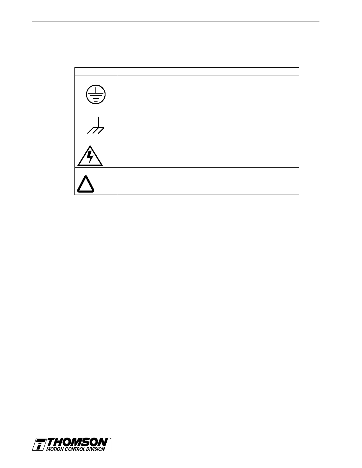
Graphical Symbols and Warning Classifications
This manual uses the following graphical symbols and warning classifications. The use of a symbol and
signal word is based on an estimation of the likelihood of exposure to the hazardous situation and what
could happen as a result of exposure to the hazard.
Example Description
!
Protective conductor terminal (Earth ground)
Chassis terminal (not a protective ground)
Risk of electrical shock.
Symbol plus DANGER, WARNING or CAUTION: These notices provide information
intended to prevent potential personal injury and equipment damage.
Artisan Technology Group - Quality Instrumentation ... Guaranteed | (888) 88-SOURCE | www.artisantg.com
Page 24
Safety 1-1
HAPTER
C
1:
Safety
Installing and Using the OMNIDRIVE
Read the complete manual before attempting to ins tall or operate the OMNIDRIVE. By reading the manual
you will become familiar with practices and procedures that allow you to operate the OMNIDRIVE safely
and effectively.
Specific Warnings and Cautions appear throughout the manual.
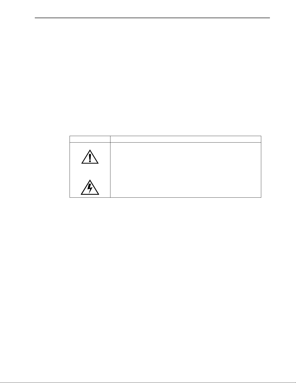
Safety Classifications
Safety notices describe the likelihood of exposure to hazardous situations and what could happen as a
result of exposure to the hazard. Following are symbols and words used to introduce the information that
is intended to prevent potential personal injury and equipment damage.
Symbols Words
or
DANGER
in death or serious injury. This signal word is limited to the most extreme situations.
WARNING
result in death or serious injury.
: Indicates an imminently hazardous situation which, if not avoided, will result
: Indicates a potentially hazardous situation which, if not avoided, could
CAUTION
in minor or moderate injury. It may be used for situations that cause property damage
only. It may also be used to alert against unsafe practices.
: Indicates a potentially hazardous situation which, if not avoided, may result
Potential Ha z a rd s
The equipment described in this manual is intended for use in industrial drive systems. This equipment
can endanger life through rotating machinery and high voltages, therefore it is essential that guards for
both electrical and mechanical parts are
use of this equipment are:
• Electric shock hazards
• Electric fire hazards
• Mechanical hazards
• Stored energy hazards
These hazards must be controlled by suitable machine design, using the safety guidelines which follow.
There are no chemical or ionizing radiation hazards.
not
removed. The main hazards which can be encountered in the
Installation Manual for Models ODM-005, ODM-005i, ODM-010, ODM-010i, ODM-020 and ODM-020i
Artisan Technology Group - Quality Instrumentation ... Guaranteed | (888) 88-SOURCE | www.artisantg.com
Page 25

1-2 Safety
Voltage Potentials
Voltage potentials for the internal drive circuitry vary from 325 Volts above to 325 Volts below earth
ground for a 240 Volt input. Voltages can exceed 450 VDC or 240 VAC within the OMNIDRIVE. All
circuits, including the connections on the front panel, should be considered “hot” when main or auxiliary
power is connected and for the time specified in the warning on the front of the drive after power is
removed.
Intro
DANGER
DC bus capacitors may retain hazardous voltages for several minutes after
input power has been remov ed, but will normally disch arge in several seconds.
Measure the DC bus voltage to verify it has reached a safe level each time
power is removed before wo rking o n the dri ve; or w ait for th e time indicated in
the warning on the front of the drive. Failure to observe this precaution could
result in severe bodily injury or loss of life.
Your Responsibilities
As the user or person installing this drive, you are responsible for determining the suitability of the product
for the intended application. Thomson Industries is neither responsible nor liable for indirect or consequential damage resulting from the inappropriate use of this product.
A qualified person is someone who is familiar with all safety notes and established safety practices, with
the installation, operation and maintenance of this equipment and the hazards involved. For more detailed
definitions, refer to IEC 364.
It is recommended that anyone who operates or maintains electrical or mechanical equipment should have
a basic knowledge of First Aid. As a minimum, they should know where the First Aid equipment is kept
and the identity of the official First Aiders.
These safety notes do not represent a complete list of the steps necessary to ensure safe operation of the
equipment. If you wish further information, please contact your nearest Thomson Industries
representative.
Artisan Technology Group - Quality Instrumentation ... Guaranteed | (888) 88-SOURCE | www.artisantg.com
Page 26

General Safety Guidelines
Electrical shock and fire hazards are avoided by using normal installation procedures for electrical power
equipment in an industrial environment. Installation must be undertaken by suitably qualified personnel.
Note that this amplifier must be installed in an industrial cabinet such that access is restricted to suitable
qualified personnel.
Mechanical hazards are associated with potentially uncontrolled movement of the motor shaft. If this
imposes a risk in the machine, then appropriate precautions must be made to electrically disconnect the
motor from the drive when personnel have access to moving parts of the machine. Note also that the
motor must be securely mounted at all times.
Stored energy hazards are both electrical and mechanical.
1. Electrical hazards can be avoided by disconnecting the drive from its power source and measuring
the DC bus voltage to verify it has reached a safe level or by waiting for the time indicated in the warning
on the front of the drive prior to removing the protective covers or touching any connections.
2. Mechanical hazards require a risk analysis on the effects of stored mechanical energy when the
machine is running at speed, as well as the potential for the conversion of electrical energy stored in the
drive being converted to mechanical energy. Electrical energy may be stored in drive for the time indicated
in the warning on the front of the drive.
The following points should be observed for the safety of personnel. These safety notes do not represent
a complete list of the steps necessary to ensure safe operation of the equipment. Contact your nearest
Thomson Industries representative for additional information.
• Only qualified personnel familiar with the equipment are permitted to install, operate andmaintain the device.
• System documentation must be available and observed at all times.
• All non-qualified personnel are kept at a safe distance from the equipment.
• The system must be installed in accordance with local regulations.
• The equipment is intended for permanent connection to a main power input. It is
intended for use with a portable power input.
• Do
• Do
• Always remove power before making or removing
• Before removing the cover of the unit, shut off the main and auxiliary power and measure
• Do
• Be careful of the DC bus and shunt terminals. High voltage is present when power is
• Never connect the DC- terminal to earth ground, the drive requires a floating DC bus.
• Do
• When operating a ODM-075 or ODM-075i with a single phase power input, the current
• Motors without thermal protection devices require a valid thermal time constant. Other-
not
nected.
not
on thedrive.
the DC bus voltage to verify it has reached a safe level or wait for the time indicated in the
warning on the front of the drive.
not
the only points where users should make connections.
applied to the OMNIDRIVE.
not
OMNIDRIVE before maintaining or repairing the unit.
limits must be set correctly.
wise the motor overload protection will not function properly.
Safety 1-3
not
power up the unit without the covers in place and the protective conductor con-
operate the unit without connecting the motor conductor to the appropriate terminal
any
connection on the unit.
make any connections to the internal circuitry. Connections on the front panel are
use the ENABLE input as a safety shutdown. Always remove power to the
Installation Manual for Models ODM-005, ODM-005i, ODM-010, ODM-010i, ODM-020 and ODM-020i
Artisan Technology Group - Quality Instrumentation ... Guaranteed | (888) 88-SOURCE | www.artisantg.com
Page 27

1-4 Safety
Artisan Technology Group - Quality Instrumentation ... Guaranteed | (888) 88-SOURCE | www.artisantg.com
Page 28

Selecting Other System Components 2-1
HAPTER
C
2:
Selecting Other System Components
This chapter reviews the OMNIDRIVE ODM-005, -005i, -010, -010i, -020 and -020i, command sources
and interfaces for the drives, and complementary motors and accessory equipment. Selection of complementary servo components allows you to efficiently connect other devices to your microdrive. Pertinent
information about each is provided to assist you in planning your servo system.
The Thomson Industries OMNIDRIVEs are part of a family of digital drives that use microcontrollers to
manage the current, velocity, and position. All system and application parameters are set in software,
which ensures repeatability of all functions and prevents element drift.
This chapter reviews the OMNIDRIVE and associated motors, command sources and interfaces. Selection
of complementary servo components allows you to efficiently connect other devices to your
OMNIDRIVE. Pertinent information about each is provided to assist you in planning your servo system.
OMNIDRIVE Overview
The OMNIDRIVEs are part of a family of universal digital drives. OMNIDRIVEs use microcontrollers
to digitally manage the current, velocity, and position. All system and application parameters are set in
software, which ensures repeatability of all functions and prevents element drift.
A single unit fully encloses all electronics. An external transformer is
connectors and indicators are accessible and clearly marked on the front panel.
not
required on the power line. All
OMNIDRIVE Features
Drive Power Ratings
Several power levels of OMNIDRIVEs are available. All models have integral power supplies1 and use
a single phase power source. They differ only in physical size, indexing capability and output power:
• ODM-005 and -005i with continuous output power of 500 Watts.
• ODM-010 and -010i with continuous output power of 1000 Watts.
• ODM-020 and -020i with continuous output power of 2000 Watts.
The OMNIDRIVEs, when combined with brushless servo motors, provide continuous torque ranging
from 0.17 Nm to 2.5 Nm (1.5 to 22.5 lb-in) and peak torque ranging from 0.48 Nm to 7.12 Nm (4.3 lbin to 63 lb-in).
High Performance Microcontroller Technology
All digital current, velocity and position loop calculations as well as the motor commutation calculation
are performed by a microcontroller.
IPM Technology
IPM (Intelligent Power Module) technology in the output stage provides a high frequency, digital PWM
(Pulse Width Modulation) sine wave that controls the current loop, including overcurrent, short circuit
and overtemperature protection.
1. ODM-00 5, -005i, -010, -010i and -020 and -020i require an external 12-24VDC power source for I/O.
Installation Manual for Models ODM-005, ODM-005i, ODM-010, ODM-010i, ODM-020 and ODM-020i
Artisan Technology Group - Quality Instrumentation ... Guaranteed | (888) 88-SOURCE | www.artisantg.com
Page 29

2-2 Selecting Other System Components
Analog and Digital Interfaces
All OMNIDRIVEs allow the user to select one of the following analog or digital command interfaces:
• ±10 Volt analog interface – position, velocity or torque control
• Presets (from one to eight binary inputs) – torque or velocity control
• Quadrature encoder digital interface – electronic gearing position follower
• Step/Direction digital interface – position control
• CW/CCW (step up/step down) interface – position control
• Indexing (available only on ODM-010i, ODM-020i, ODM-030i, ODM-075i and
ODM- 150i).
Encoder Control
A single, motor mounted encoder provides complete commutation information and velocity feedback.
Low velocity regulation is enhanced by the use of a 8000PPR (pulses per revolution) incremental encoder.
Encoder Output
A selectable output allows the encoder resolution to be specified for maximum performance without
adding circuitry. Outputs are differential line drivers capable of dividing the motor encoder signal, PPR,
by a factor of 1, 2, 4 or 8.
Digital I/O
Digital I/O channels allow the user to program the drive to fit the specific application. Power for the I/O
must be supplied by an 12-24 VDC external I/O power supply. Selections include:
• Four selectable (INPUT1, INPUT2, INPUT3 and FAULT RESET), current sinking, optically isolated, active high inputs.
• One dedicated, control (ENABLE), current sinking, optically isolated, active high input.
• Two selectable, current sourcing, optically isolated and short circuit protected, active high
outputs.
• Two dedicated (BRAKE/DRIVEENABLED and DRIVE READY), normally open relay
outputs.
Analog I/O
Two analog inputs are dedicated to current limits and two analog outputs can be customized to fit the
application:
• One dedicated 10 bit, 0 – 10 Volt, analog inputs (EXTERNAL CURRENT LIMIT)
• One selectable, ±10 Volt analog outputs, one 12-bit and one 8-bit (ANALOG).
AC Input Power
OMNIDRIVEs covered by this manual are powered directly from a main 100-240 VAC single phase line.
Personality Module
EEPROM (electrically erasable programmable read-only memory) stores both motor and application
specific settings and parameters for the drive.
Artisan Technology Group - Quality Instrumentation ... Guaranteed | (888) 88-SOURCE | www.artisantg.com
Page 30

Selecting Other System Components 2-3
Multiple Protection Circuits
Device and circuit protection, and diagnostic information is provided by:
• Bi-color single point LED
• Overtemperature, short circuit and overcurrent protection for the power output
2
T (power-time) protection
• I
• Bus Overvoltage
• Bus Undervoltage
• Overspeed
• Fault diagnostics
• Watchdog timers provide fail-safe operation
Serial Command Sources
OMNIDRIVEs are configured and controlled via a serial communication link. Commands may be issued
from a variety of sources through a serial communications port. Possible command sources include:
• Personal computers
• Host computers
• Programmable Logic Controllers
• Motion controllers
• TouchPad.
The serial communication interface for the OMNIDRIVE supports:
• RS-232 and the four wire RS-485 communications standards
• NRZ (non-return to zero) asynchronous serial format
• Baud rates: 1200, 2400, 4800, 9600 and 19200
• Parity generation and checking: Even, Odd or None.
Connection of communication cables between the drive and user-supplied equipment is described in the
following sections:
One OMNIDRIVE - "Single Position RS-232 Set-up"
Multiple OMNIDRIVEs - "Multiple Position RS-485 Communications".
Analog Command Sources
In the analog mode of operation, the OMNIDRIVE requires a variable ±10 Volt DC external analog signal
capable of driving the servo regulator’s command input at an input impedance of 13.3 kOhms. Choose a
source such as a PLC (programmable logic controller), the DAC (digital-to-analog converter) of a computer, or a motion controller that meets this requirement.
Differential or single-ended line drivers may supply the signals for the auxiliary encoder inputs, step and
direction inputs, and step up/down inputs. The differential signal must be capable of supplying at least 5
mA with 2.0 Volts across the + and - inputs. A differential signal source provides the best noise margin
of all the interface circuit options. Single-ended signals from TTL drivers must be capable of sourcing
or sinking 5 mA.
In the preset mode, the controlling device should be capable of sourcing 10 mA into the digital inputs.
Installation Manual for Models ODM-005, ODM-005i, ODM-010, ODM-010i, ODM-020 and ODM-020i
Artisan Technology Group - Quality Instrumentation ... Guaranteed | (888) 88-SOURCE | www.artisantg.com
Page 31

2-4 Selecting Other System Components
I/O Interface
Analog Input
One analog input channel is accessible to the user. The analog input limits the peak current available from
the drive.
• I LIMIT (current limit)
The analog signal must be within 0-10 Volt range and single-ended.
If this signal is not provided, the peak current of the drive may be set in software through the Drive
Parameter window.
Analog Output
One analog output channel may be defined by the user through software:
• ANALOG is a ±10 Volt signal. The allowable current draw of the load is ±2 mA
This analog output is designed for monitoring purposes only. This signal should not be used for control
purposes due to the relatively high ripple voltage (1%).
Digital Inputs
Control Inputs
One optically isolated, single ended, active high, dedicated control input provides the controller ENABLE
function. This input operates with switch closure or sourcing type transistor outputs.
The current rating is 10 mA maximum.
Selectable Inputs
Four optically isolated, single ended, active high inputs (INPUT1, INPUT2, INPUT3 and FAULT
RESET) support logic type interfaces. The input circuits operate with switch closure or sourcing type
transistor circuits.
The current rating of each input is 10 mA maximum.
Digital Outputs
Control Outputs
Two normally open relays are dedicated control outputs to the following signals:
The current ratings of each relay is 1 Amp at 30 VDC.
If using a motor with the 90VAC brake option, a user-provided relay may be driven by these outputs up
to the specified levels. Refer to "BRAKE/DRIVE ENABLE Application Exampl" for information about
the necessary hardware connections. Consult the I/O Configuration in the on-line OMNI LINK help for
additional information about the software parameters.
TIP
NOTE: Power for the I/O must be supplied by an external
12 - 24 VDC power source.
• BRAKE/DRIVE ENABLED
• DRIVE READY.
Artisan Technology Group - Quality Instrumentation ... Guaranteed | (888) 88-SOURCE | www.artisantg.com
Page 32

Selectable Outputs
Two optically isolated, single ended, active high, current sourcing, discrete output channels provide logic
outputs under software control.
Each selectable output channel is capable of sourcing 50 mA maximum and is optically isolated and short
circuit protected.
Auxiliary Encoder Interface
The external encoder I/O port permits quadrature type encoder signals for applications, such as electronic
gearing.
Encoder Inputs
Software automatically selects the appropriate input based on the command source:
• Master Encoder
• Step/Direction
• Step Up/Step Down.
Encoder Output
The resolution of the encoder output channel is under software control. The motor encoder signal is
divided by 1, 2, 4 or 8 to provide an output from a differential line driver measured in PPR (pulses per
revolution). The maximum encoder frequency output is 1 MHz (4 MHz quadrature).
Selecting Other System Components 2-5
Autotuning
Digital auto tuning allows easy setup. All adjustments are made in software, which immediately sets the
servo system compensation parameters. This eliminates the time-consuming adjustments required by
potentiometers.
Agency Approvals
Interface Cables
Standard motor power and encoder feedback cables, as well as communications cables, are available to
complete your motion control system and provide reliable, trouble free start-up. Use of factory supplied
cables is required for compliance to the European Electromagnetic Compatibility (EMC) Directive and
to protect your warranty rights.
TIP
• UL listed
• cUL listed
• CE marked
NOTE:
state, please refer to "IOUT Signal Generation" for additional
information.
If a controller requires synchronization to a specific output
OMNI LINK Software
A Windows based software interface provides start-up selections. Tasks are organized for efficient set
up, control and maintenance. Context sensitive, on-line help provides immediate assistance.
Installation Manual for Models ODM-005, ODM-005i, ODM-010, ODM-010i, ODM-020 and ODM-020i
Artisan Technology Group - Quality Instrumentation ... Guaranteed | (888) 88-SOURCE | www.artisantg.com
Page 33

2-6 Selecting Other System Components
• Set up is simplified by a series of logically arranged set up screens.
• Files can be stored and printed for on-line or off-line modification, and on-site or off-site
back-up.
• Diagnostic and set up tools make system integration easy.
• Critical information is available with complete on-line help.
• User defined velocity, acceleration, position and torque parameters.
• Tuning and diagnosis is aided with an on-screen dual channel digital oscilloscope.
• On-screen meters and software tools provide rapid debugging and measurement.
Motors
The OMNIDRIVE is compatible with many motors, both Thomson motors and motors from other manufacturers. Drive and motor parameters for all compatible motors are programmed into each
OMNIDRIVE at the factory.
OMNI LINK software speeds drive and motor set up by predefined parameters for each drive and motor
combination.
Refer to the Torque/Speed curves in the Thomson Motion Control Catalog and Handbook or contact your
local Thomson distributor for motor sizing and compatibility assistance.
Custom motors or motors not manufactured by Thomson may be interfaced. Contact Product Support for
assistancePhone and fax numbers for product related assistance are listed under “Applications Engineers
and Field Service” on the inside rear cover.. * (see Appendix B).
• Power and feedback cables are potted and molded with 360 degree shielding.
• AC line filters.
• Breakout boards for I/O control and encoder interface.
• TouchPad - a compact and highly portable input and display device.
European Union Requirements
OMNIDRIVEs conform to the following European Union Directives:
• Low Voltage Directive (72/23/EEC, 93/68/EEC)
• Electromagnetic Compatibility Directive (89/336/EEC, 92/31/EEC, 93/68/EEC)
Compliance with the EEC Directives is contingent on:
Installation of AC line filters between the power source and the drive, and
A.
Use of factory authorized cables to connect motors.
B.
“European Union EMC Directives” on page 5-4.
Use of this product with other non-CE products or in a manner inconsistent with established testing
requirements invalidates the CE registration as declared by Thomson.
Artisan Technology Group - Quality Instrumentation ... Guaranteed | (888) 88-SOURCE | www.artisantg.com
Page 34

OMNI LINK Installation 3-1
HAPTER
C
3:
OMNI LINK
Installation
Installation of OMNI LINK on a PC is covered in this chapter, which:
• Lists the minimum PC hardware and software necessary to run OMNI LINK.
• Provides step-by-step instructions on how to load OMNI LINK.
• Shows you how to start and quit OMNI LINK and introduces the Drive Window,
the main command window for OMNI LINK.
• Instructs you on how to access on-line help.
Instructions for using the features available in OMNI LINK are detailed in on-line help. To access the
Help menu, depress the F1 key.
Hardware and Software Requirements
The minimum personal computer (PC) requirements to run the software are:
• A DOS computer with a 286 microprocessor
• A hard disk, with 2.0 MB of free disk space
• 3½ inch, 1.44MB floppy disk drive
• 2 MB of RAM
• A Video Graphics Array (VGA) monitor
• Microsoft Windows version 3.1
• A mouse is recommended.
Windows must be installed on your PC. If Windows is
Microsoft manual to install Windows on your computer.
not
already installed, refer to the appropriate
Installation Manual for Models ODM-005, ODM-005i, ODM-010, ODM-010i, ODM-020 and ODM-020i
Artisan Technology Group - Quality Instrumentation ... Guaranteed | (888) 88-SOURCE | www.artisantg.com
Page 35

3-2 OMNI LINK Installation
Installing OMNI LINK
To install OMNI LINK software on a hard drive:
1. Make a backup copy of the OMNI LINK disk in one of the following ways:
• Copy the OMNI LINK disk using the disk menu in the Windows File Manager.
• If your computer has only one floppy disk drive, type from the DOS command line prompt
diskcopy a: b:
the SOURCE (OMNI LINK) disk and when to insert the TARGET (blank) disk.
2. If Windows is
If Windows is already running, close any open applications.
3. Insert the OMNI LINK disk into a 1.44MB floppy disk drive, typically drive A:, and close the
drive door.
not
running, type
and then press
win
at the DOS prompt (
ENTER
. The software will prompt you when to insert
C:>
).
4. Choose
5. Type
, from the File menu in Windows Program Manager.
Run
a:setup
and then press
tializing. The message box may be present for up to 40 seconds, depending on the speed of the
PC.
6. A dialog box requires you to confirm whether or not OMNI LINK should be installed on the hard
drive (C: drive) of the PC.
• To install OMNI LINK, choose
• To stop the installation, choose
7. Setup then asks where you would like to install OMNI LINK.
• To accept the path that Setup proposes in the
• To choose another directory, type a new path in the
You will
not
have the opportunity to confirm your entry so type carefully.
• To return to the initial Setup window, choose
• To stop the installation, choose
• To obtain on-line help with the installation, Choose
8. A status bar will keep you informed of the installation progress. When Setup is complete, choose
or press
OK
ENTER
Starting and Quitting OMNI LINK
ENTER
. A message box will appear saying that the setup is ini-
C
ontinue
. You are returned to Windows.
xit
E
. You will return to Windows.
xit
E
to return to Windows.
, or press
Path:
B
ack
ENTER
, and continue with the next step.
box (c:\omnilink\...), choose
box, and then choose
Path:
.
.
H
elp
C
ontinue,
C
ontinue
.
Setup automatically creates the OMNI LINK program group and then returns you to Windows. The OMNI
LINK program group provides access to the OMNI LINK application icon,
From the C:> Prompt
TIP
1. Type
This step assumes OMNI LINK wa s loaded into the
setup.
win c:\omnilink\omnilink.exe
.
c:\omnilink
directory during
The OMNI LINK start-up screen will open.
Artisan Technology Group - Quality Instrumentation ... Guaranteed | (888) 88-SOURCE | www.artisantg.com
Page 36

From Windows
Tool bar buttons provide
quick access to common
commands and windo ws
Hypertext links to specific
items in online Help
Status bar reveals current
menu selection and statu s
information
Buttons perform typical Windows functions such as
sizing or scrolling, opening or closing windows.
Quick Start
Pop-up menus accesses
PC-based commands
Online Help e xplains tasks
and commands
x
d
OMNI LINK Installation 3-3
TIP
1. Choose the OMNI LINK program group from the Program Manager in Windows.
If the OMNI LINK window is
(ALT+TAB) until the OMNI LINK title bar and icon are highlighted, or select
OMNI LINK from the list in the Window menu.
not
active, hold down ALT and press TAB
2. Choose the OMNI LINK icon from the OMNI LINK program group.
The OMNI LINK start-up screen will open.
The OMNI LINK Start-Up Screen
When OMNI LINK starts for the first time, its default instructions are:
• Display the Help menu - Quick Start.
• Present the Drive Select window. The Drive Select window offers Drive 0, which is the
default drive address assigned at the factory.
The default OMNI LINK Start-up screen is shown below. The comments point out many of the Windows
controls that are available in OMNI LINK.
TIP
Drive Select dialog box.
The Drive Select dialog bo
is displayed automatically
when OMNI LINK is starte
to specify which drive to
set up. It presents the
factory default drive
address (Drive 0) for the
OMNI LINK displays the Help menu –
To disable this automatic display, deselect the menu item
from the Help menu.
Quick Start
– when it is first accesse d.
Show Quick Start
Version Level
The release level and date for OMNI LINK may be displayed by selecting
Help menu. This information also appears in the initial OMNI LINK screen. The About OMNI LINK
window includes additional data about system resources typically displayed in Windows Help.
OMNI LINK from the
bout
A
Artisan Technology Group - Quality Instrumentation ... Guaranteed | (888) 88-SOURCE | www.artisantg.com
Installation Manual for Models ODM-005, ODM-005i, ODM-010, ODM-010i, ODM-020 and ODM-020i
Page 37

3-4 OMNI LINK Installation
The Readme File
A file, titled README, may be included in the OMNI LINK directory. This file contains installation
instructions, change notes from previous revisions, and information that became available after this manual was printed. After you install OMNI LINK you can access this file by choosing the Read Me icon in
the OMNI LINK window or by using Microsoft Write or an equivalent application program to view the
readme.wri
file
in the directory path where OMNI LINK is installed.
Miscellanious Files
Firmware Files
Firmware files are supplied in the Miscellaneous directory on the OMNI LINK diskette.
The current revision level of drive firmware, excluding the TouchPad firmware, is displayed in the Drive
Information window of OMNI LINK. The current revision level of TouchPad firmware is displayed as
part of the TouchPad initialization when a TouchPad is connected to the drive.
The types of files and their functions are:
• Firmware – Main Operating firmware for the drive
• Boot Block – Drive Initialization firmware for the drive
Artisan Technology Group - Quality Instrumentation ... Guaranteed | (888) 88-SOURCE | www.artisantg.com
Page 38

Unpacking, Inspecting, and Storing 4-1
HAPTER
C
4:
Unpacking,
Inspecting, and
Storing
This chapter describes four steps which should ensure that the drive functions correctly. The steps include:
• Unpacking the OMNIDRIVE
• Inspecting the drive for shipping damage
• Testing the basic functionality of the drive
• Guidelines for storing the drive.
Unpacking the Drive
1. Remove the OMNIDRIVE from the shipping carton and remove all packing materials from the unit.
The materials and carton may be retained for storage or shipment of the drive.
2. Check all items against the packing list. A label located on the side of the unit identifies:
• Model number
• Serial number
• Manufacturing date code.
Inspection Procedure
To protect your investment and ensure your rights under warranty, we recommend the following steps
be performed upon receipt of the unit:
• Inspect the unit for any physical damage that may have been sustained during shipment.
• Perform the drive checkout test to verify the functionality of the unit.
If you find damage, either concealed or obvious, contact your buyer to make a claim with the shipper. If
degraded performance is detected when testing the unit, contact your distributor or Thomson Industries
to obtain a Return Material Authorization (RMA). Do this as soon as possible after receipt of the unit.
“Our Warranty” lists the period and conditions under which OMNIDRIVEs are warranted against defects.
Installation Manual for Models ODM-005, ODM-005i, ODM-010, ODM-010i, ODM-020 and ODM-020i
Artisan Technology Group - Quality Instrumentation ... Guaranteed | (888) 88-SOURCE | www.artisantg.com
Page 39

4-2 Unpacking, Inspecting, and Storing
Testing the Unit
Drives are burned-in and individually tested before they leave the factory. However, damage may occur
during shipping. Perform the procedures below to ensure the OMNIDRIVE is operational and undamaged.
Abbreviated directions for connecting the drive to a motor and a PC are provided.
The test requires:
• Approximately 20 minutes to complete
• A motor with appropriate power and encoder cables
• A PC with the OMNI LINK software package installed
• An RS-232 communications cable
• A single phase 100-240 VAC, 50/60 Hz power source. Standard wall outlet power is suit-
able for verification testing of OMNIDRIVEs.
• A test cable constructed from two normally open switches, several pieces of 1.5 mm
(16 AWG) wire and a mating connector.
During the test, power is removed several times. Always neasure the DC bus voltage to verify the bus
capacitors are fully discharged, or wait for the time indicated in the warning on the front of the drive. The
bus capacitors must be fully discharged for the subsequent steps to be valid.
If problems are encountered during this procedure, refer to “Troubleshooting” on page 11-3, review other
appropriate sections in this manual, or call your local Thomson Industries distributor.
Intro
WARNING
!
Perform the initial powe r-up with the motor s haft disconnecte d from a load and
the shaft key removed . Improper wiring or undiscovered s hipping damage could
result in undesired motor motion. Be prepared to remove power if excessive
motion occurs.
2
Artisan Technology Group - Quality Instrumentation ... Guaranteed | (888) 88-SOURCE | www.artisantg.com
Page 40

Unpacking, Inspecting, and Storing 4-3
Hardware Set Up
Make the connections described below.
1. Connect an external I/O power supply (12-24VDC) to J1-5(+) and J1-6(-), or J1-26(+)
and J1-13(-).
2. Connect an RS-232 cable between the serial port on the PC and the J5 connector on the
OMNIDRIVE. A simple 3 wire cable is depicted in the figure below.
3. Connect a Motor/Feedback cable from the motor to the J2 connector on the drive.
4. Connect a jumper wire with a toggle switch between J1-20 (ENABLE) and J1-26 (+24VDC).
This provides manual control for enabling or disabling the drive. The figure below shows the
jumper, including its normally open toggle switch.
5. Connect a power cable between the external 100/240 VAC, 50/60 Hz power source and the L1,
L2/N and (Gnd) connections.
Drive Checkout Test
This test sequentially verifies that:
• Drive power wiring is correct and start-up logic is functioning
• The drive and motor are correctly wired
• Drive serial communications are operational
Before beginning “Initial Power-up”, please check the following:
• All wiring and mounting to verify correct installation
• Input voltages to ensure they do not exceed specifications for the drive or motor.
Initial Power-up
1. Verify the AC power is within specifications at the terminal strip.
2. Switch the AC Power to ON and verify the Status LED is green.
3. Switch the power OFF and wait until the DC Bus Voltage is below 30 Volts, to prevent electrical
shock.
4. Connect the motor windings to:
• R (TB1-6) for the Phase R winding
• S (TB1-7) for the Phase S winding
• T (TB1-8) for the Phase T winding
• (TB1-9) for the Ground connection.
5. If a brake motor is being used for the test, connect the brake relay:
• BRAKE ENABLE + (J1-49) to the Motor Brake+
Installation Manual for Models ODM-005, ODM-005i, ODM-010, ODM-010i, ODM-020 and ODM-020i
Artisan Technology Group - Quality Instrumentation ... Guaranteed | (888) 88-SOURCE | www.artisantg.com
Page 41

4-4 Unpacking, Inspecting, and Storing
Intro
DRIVE
Close to ENABLE drive
Close to RESET faults
XMT
RCV
COM
J4
2 RCV
3 XMT
5 COM
J1
26 +24V
20 ENABLE
21 FAULT RESET
J2
Motor
Encoder
TB1
Phase R 1
Phase S 2
Phase T 3
Motor Gnd 4
TB1
L1 7
L2/N 8
Gnd 9/10
TB1
L1 7
L2/N 8
L3 9
Gnd 10
100-240 VAC
50/60 Hz
Single Phase
Power Source
Gnd = Pin 9 for DDM-010, DDM-020, DDM- 030
Gnd = Pin 10 for DDM-075 using single phase
OD-010, OD-020, OD-030
OD-075 USING SINGLE PHASE
or
100-240 VAC
50/60 Hz
Three Phase
Power Source
IGURE
F
4.1
Connection Diagram
• BRAKE ENABLE - (J1-50) to the Motor Brake-
6. Switch the AC Power to ON and verify the Status LED is green.
7. Switch the power OFF and wait until the DC Bus Voltage is below 30 Volts.
Artisan Technology Group - Quality Instrumentation ... Guaranteed | (888) 88-SOURCE | www.artisantg.com
Page 42

Communications Verification
8. Start OMNI LINK on the PC.
9. Close any windows that are open in OMNI LINK.
Unpacking, Inspecting, and Storing 4-5
10. Select
P
C Set Up
from the C
ommunications menu in OMNI LINK.
11. Verify the communication port settings match those of the drive, then select OK. Factory default
drive settings are:
• Baud Rate:
• Data Bits:
• Parity:
• Stop Bits:
• Serial Port:
9600
8
None
1
COM1
Assignment of communications ports on PCs varies between manufacturers. The COM port setting
for the drive and PC must match. Refer to “Troubleshooting” on page 11-3 if communication
problems are encountered.
12. Switch AC power ON.
13. Select
R
ead Drive Parameters
from the C
ommunications menu in OMNI LINK.
14. Select OK in the Drive Select dialog box. A dialog box indicating that the PC is reading drive
parameters should appear.
If this dialog box does
not
appear, a message appears that advises you to check the COM settings
and the communication cable. If necessary, refer to “Troubleshooting” on page 11-3 for instructions on how to perform these checks.
Initial Drive Operation
15. When the message appears that a motor must be selected, choose OK. The Drive Select dialog
box is selected with Motor Selection active.
16. Select the appropriate motor from the drop-down Motor Selection box.
17. Choose OK when the message appears advising that the drive must reset. A change in motor
parameters requires a software reset.
18. Choose
19. Select the
from the Drive Setup window.
Close
Control P
icon from the Drive Window.
anel
20. Close the connection between J1-26 and J1-20 to enable the drive.
21. Holding torque should be sufficient so that the shaft is either immovable or very resistant to rotation.
22. Move the Slide Bar in the Control Panel window to the right and then to the left. Verify that the
motor rotates:
• CW as the Slide Bar is moved right of center, and
• CCW as the Slide Bar is moved left of center.
If the motor rotates in the wrong direction (CCW when the slide bar is set to the right of center)
or jumps and locks-up, motor phasing and encoder feedback phasing may be incorrect. If necessary,
refer to Chapter 11, “Maintenance and Troubleshooting” for instructions on how to correct the
motor power connections at TB1-1, -2, -3 and -4 or the encoder feedback connections at J2.
23. Choose
Set to Z
. The motor will stop rotating.
ero
Installation Manual for Models ODM-005, ODM-005i, ODM-010, ODM-010i, ODM-020 and ODM-020i
Artisan Technology Group - Quality Instrumentation ... Guaranteed | (888) 88-SOURCE | www.artisantg.com
Page 43

4-6 Unpacking, Inspecting, and Storing
24. Choose
25. Choose
26. Open the connection between J1-26 and J1-20 to disable the drive.
27. Choose
A drive completing these steps is functional. If the OMNIDRIVE did
“Maintenance and Troubleshooting” on page 11-1.
TIP
For information on testing digita l and analog signals , refer to , “T esting Analog
Output” on page 11-8 and “Testing Analog Input” on page 11-9
Storing the Unit
Return the OMNIDRIVE to its shipping carton using the original packing materials to enclose the unit.
Store the drive in a clean, dry place that will
and verify the motor shaft can be rotated by hand.
Drive D
Drive E
isable
and verify the motor shaft has holding torque. (i.e., The shaft cannot be
nable
moved or moves with resistance.)
from the Control Panel window.
Close
not
pass the steps above, refer to
not
exceed the following ranges:
• Humidity: 5% to 95%, non-condensing
• Storage temperature: -40° to 70° Celsius (-40° to 158° Fahrenheit).
Artisan Technology Group - Quality Instrumentation ... Guaranteed | (888) 88-SOURCE | www.artisantg.com
Page 44

Installation 5-1
HAPTER
C
5:
Installation
Mechanical Installation Requirements
1. Mount the unit in an enclosure providing protection to IP54 (protected against dust and splashing
water), or IP65 (dust free and protected against water jets) if the work environment is poor.
Many NEMA (National Electrical Manufacturers Association) Type 4 cabinets provide this level
of protection. Minimum cabinet requirements are:
• Depth: 24.38 cm (9.6 inches).
• Adequate sizing and/or ventilation to dissipate the heat generated by the OMNIDRIVEs .
Refer to “Power Dissipation” on page E-7 for the amount of heat generated by
OMNIDRIVEs and enclosure sizing equations.
2. Minimum unobstructed surrounding space for cooling air intake and fan exhaust:
• Above: 5 cm (2 inches)
• Below: 5 cm (2 inches)
• Sides: 1.25 cm (0.5 inches)
• Front: 7.5 cm (3.0 inches) for cable clearance.
Intro
CAUTION
!
If the cabinet is ventilated, use filtered or conditioned air to prevent the accumulation of dust and dirt on electronic components. The air should be free of
oil, corrosives, or electrically conductive contaminates.
3. Position the drive in a vertical position on a flat, solid surface that meets the mounting hardware
should meet the following weight, vibration and shock, altitude and humidity, airflow clearance,
and temperature requirements. Unit weights are:
• ODM-010 and ODM-010i: 1.7 Kg (3.7 lbs)
• ODM-010 and ODM-010i: 2.05 Kg (4.5 lbs)
• ODM-020 and ODM-020i: 2.0 Kg (4.4 lbs)
Vibration and shock, altitude and humidity limits are:
• Vibration: 2g at 10 to 2000 Hz
• Shock: 15g 11 msec half sine
• Altitude: 1500 meters (5000 feet),
Derate power performance 3% for each 300 m above 1500 m (1000 ft above 5000 ft).
• Humidity: 5% to 95% non-condensing
Ambient operating temperature range and airflow clearances are:
•0 ° to 55° Celsius (32° to 131° Fahrenheit).
• 50.8 mm (2 inches) above and below unit for airflow.
4. Bolt the unit to the cabinet using the mounting slots in the drive. Mounting dimensions are
shown in Figure 5.1. The recommended size of mounting hardware is:
• M5 Metric (1/4-20 equivalent), or
Installation Manual for Models ODM-005, ODM-005i, ODM-010, ODM-010i, ODM-020 and ODM-020i
Artisan Technology Group - Quality Instrumentation ... Guaranteed | (888) 88-SOURCE | www.artisantg.com
Page 45

5-2 Installation
• #10 MS bolts.
Intro
Intro
IGURE
F
5.1
ODM-005 and ODM-005i Mounting Dimensions
B
B
B1
A2
A2
A3
A3
A4
A4
A
A
A1
A1
A5
A5
B1
B2
B2
B4
B4
B3
B3
A6
A6
A8
A8
A10
A10
A11
A11
A7
A7
A9
A9
Minimum Unobstructed Surrounding Space
for Cooling and Exhaust Air
Above 50.8 mm (2 inches)
Below 50.8 mm (2 inches)
Sides 12.5 mm (0.5 inches)
for Cable Bend Radius
Front 76.2 mm (3 inches)
C
C
C1
C1
T
ABLE
5.1
ODM-005 and -005i Mounting Dimensions
Dimension Dimension
mm inches mm inches
A 198.12 7.80 B 72.60 2.86
A1 184.9 7.28 B1 65.02 2.56
A2 6.35 0.25 B2 38.10 1.50
A3 13.0 0.51 B3 18.54 0.73
A4 6.07 2.39 B4 13.21 0.52
A5 94.49 3.72 B5 5.58 0.22
a
A6
5.0 0.20
A7 22.10 0.87 C 146.05 5.75
A8 31.75 1.25 C1 129.03 5.08
A9 8.64 0.34
A10 31.75 1.25
A11 57.15 2.25
a. Power Cable bracket extends up to 20mm (0.80 inches)
Artisan Technology Group - Quality Instrumentation ... Guaranteed | (888) 88-SOURCE | www.artisantg.com
Page 46

Installation 5-3
IGURE
F
5.2
ODM-010, -010i, -020 and -020i Mounting Dimensions
B
A2
A
A1
Minimum Unobstructed Surrounding Space
for Cooling and Exhaust Air
Above 50.8 mm (2 inches)
Below 50.8 mm (2 inches)
Sides 12.5 mm (0.5 inches)
for Cable Bend Radius
Front 76.2 mm (3 inches)
B1
B2
B4
B3
A3
A4
A5
A6
NOTE: Fan on ODM-020 only
A8
A10
A7
A9
A11
C
C1
T
ABLE
5.2
ODM-010, -010i, -020 and -020i Mounting Dimensions
Dimension Dimension
mm inches mm inches
A 198.12 7.80 B 97.30 3.83
A1 184.9 7.28 B1 65.02 2.56
A2 6.35 0.25 B2 38.10 1.50
A3 13.0 0.51 B3 18.54 0.73
A4 6.07 2.39 B4 13.21 0.52
A5 94.49 3.72 B5 5.58 0.22
a
A6
5.0 0.20
A7 22.10 0.87 C 146.05 5.75
A8 31.75 1.25 C1 129.03 5.08
A9 8.64 0.34
A10 31.75 1.25
A11 57.15 2.25
a. Power Cable bracket extends up to 20mm (0.80 inches)
Installation Manual for Models ODM-005, ODM-005i, ODM-010, ODM-010i, ODM-020 and ODM-020i
Artisan Technology Group - Quality Instrumentation ... Guaranteed | (888) 88-SOURCE | www.artisantg.com
Page 47

5-4 Installation
Interface Connections
Input/output and power cables connect to the front panel of a OMNIDRIVE , no internal connections are
necessary.
Intro
DANGER
!
The user is responsible for conforming with all applicable local, national and
international code s. Wiri ng prac tices , ground ing, dis conn ects a nd ove rcur rent
protection are of part icular importance. F ailure to observe thi s precaution could
result in severe bodily injury or loss of life.
I/O Connections are fully described in the following sections:
• “J1 – Controller” on page 6-1 defines the controller connections
• “J2 – Encoder” on page 6-25 defines the motor encoder connections
• “J5 – Serial Port” on page 6-27 defines the RS-232/RS-485 serial port connections
Power Connections are fully described in the following sections:
• “Power Connections” on page 7-1 defines the AC, DC Bus and Motor power connections.
Specific operational set ups are depicted in Figure 8.1 through Figure 8.11 (pages 8-1 through 8-32,
respectively). These figures cover velocity and torque mode controls for:
• Analog Controllers in velocity or torque modes,
• Preset Controllers in velocity or torque modes,
• Position Followers using a Master Encoder,
• Position Followers using a Step/Direction signal,
• Position Followers using Step Up/Down signals,
• Incremental Indexing over a specific distance,
• Registration Indexing from a mark, or
• Absolute Indexing to a home position.
Wiring
Wiring sizes and practices, as well as grounding and shielding techniques are described in the sections
listed below. Refer to the “Motor Power Contact and Wire Size Recommendations” on page 7-3 for
graphic depictions and recommended wire gaging.
The descriptions represent common wiring practices and should prove satisfactory in the majority of
applications.
Minimum wire gages for power cables are listed in:
• Motor Power Contact and Wire Sizing Recommendations ,
• “TB1 - AC Power Terminals” on page 7-5.
Electromagnetic Compatibility
General Guidelines
Appendix C, “Electromagnetic Compatibility Guidelines for Machine Design” contains guidelines for
reducing electrical noise and increasing electromagnetic compatibility (EMC) plus a discussion of electromagnetic interference (EMI).
European Union EMC Directives
The OMNIDRIVEs are designed and tested to meet the European EMC Directive. Declarations of conformity, which enumerates the standards used, are included in the manual.
Artisan Technology Group - Quality Instrumentation ... Guaranteed | (888) 88-SOURCE | www.artisantg.com
Page 48

Installation 5-5
Intro
WARNING
Installation requirements are necessary to meet the directives:
1. Use of factory supplied cables,
2. Use of an external AC line filter, and
Large leakage currents e xist in AC line filters . They must be ground ed properly
before applying power. Filter capacitors retain high voltages after power
removal. Before ha ndling the equipment, volta ges should be measured to de termine safe levels prior to handling the equipment.
Failure to observe this precaution could result in severe bodily injury.
3. If an external supply powers the I/O, grounding of this power supply is required.
The following diagrams show the mounting dimensions for single phase AC Line Filters.
Table 5.3 shows a typical filter selection matrix for OMNIDRIVEs. All the filters identified below are
manufactured by Schaffner or Roxburgh and are widely available. There are many AC line filter manufacturers whose filters can be successfully integrated. Thomson Industries recommends Schaffner or
Roxburgh filters based on our test results, but the machine builder is responsible for the suitability of the
filter selection in a specific application. These filters can be used for distributing power to multiple drives,
rather than using an individual filter for each drive. Further information is available from Schaffner (1800-367-5566) or Roxburgh (01724.281770 [011.44.1724.281770 from the USA]).
AC line filters for use with OMNIDRIVEs are listed below:
T
ABLE
5.3
AC Line Filters for OMNIDRIVES
Part Number
Drive Roxburgh Schaffner
ODM-005 and
ODM-005i
ODM-010,
ODM-010i and OD-010
ODM-020,
ODM-020i and OD-020
OD-030 MIF 32, MDF 36 FN 350-30
OD-075
(3- phase)
MIF 06, MDF 06 FN 350-8
MIF 10, MDF 16 FN 350-12
MIF 23, MDF 18 FN 350-20
MIF 330, MIF 336 FN 351-36
The Roxburgh filters differ in the number of stages. The MDF (Motor Drive Filters) filters are single
stage filters; the MIF (Motor Inverter Filters) filters are three-stage filters. The three-stage filter will
remove more of the noise, but the cost is more panel space in the higher current filters. In the lower current
filters (<50 A), the panel space used is less for the MIF filters.
The Schaffner filters are single-stage filters. These differ from the Roxburgh filters in component types,
values and placement. The leakage current is generally lower, but the amount of attenuation is lower too.
These filters will work if the amount of noise in the environment is low, or if the design of the machine
is such that only a nominal amount of attenuation is needed.
Basic guidelines for reducing electrical noise and increasing electromagnetic compatibility (EMC) are
listed in “Electromagnetic Compatibility Guidelines for Machine Design” on page C-1.
Installation Manual for Models ODM-005, ODM-005i, ODM-010, ODM-010i, ODM-020 and ODM-020i
Artisan Technology Group - Quality Instrumentation ... Guaranteed | (888) 88-SOURCE | www.artisantg.com
Page 49

5-6 Installation
AC Line Filters
IGURE
F
5.3
MIF Single Phase AC Line Filter Mounting Diagram
T
ABLE
5.4
MIF Single Phase AC Line Filter Engineering Specifications
SINGLE PHASE
6A
SINGLE PHASE
10A
DIMENSIONAL DATA
MEASUREMENT mm in mm in mm in
A 170 6.7 214 8.4 214 8.4
A1 152 6.0 192 7.6 192 7.6
A2 9 0.4 11 0.4 11 0.4
B 92 3.6 145 5.7 204 8.0
B1 55 2.2 104 4.1 164 6.6
B2 18 0.7 20 0.8 20 0.8
C 25 1.0 40 1.6 47 1.8
C1 10 0.4 16 0.6 19 0.8
C2 15 0.6 24 1.0 28 1.0
ELECTRICAL and MECHANICAL SPECIFICATIONS
Voltage/Freq.
Current
Overload Current
Temperature
Leakage Current
Electric Strength
Power Loss
Terminals
250 VAC @ 50/50 Hz 250 VAC @ 50/50 Hz 250 VAC @ 50/50 Hz
6A @ 50°C 10A @ 50°C 23A @ 50°C
150% 1 minute
200% 1 second
150% 1 minute
200% 1 second
-25 to 95°C -25 to 95°C -25 to 95°C
5 mA @ 240V, 50 Hz 46 mA @ 240V, 50 Hz 200 mA @ 250V, 50 Hz
2500 VAC/1 minute 2500 VAC/1 minute 2500 VAC/1 minute
3.5 Watts (Full Load) 2.7 Watts (F ull Load) 10 Watts (Full Load)
2mm sq. spring clamp M4 screw cross/ sq.
M4 screw cross/ sq.
2x 2.5mm
SINGLE PHASE
23A
150% 1 minute
200% 1 second
2x 2.5mm
Artisan Technology Group - Quality Instrumentation ... Guaranteed | (888) 88-SOURCE | www.artisantg.com
Page 50

Installation 5-7
SINGLE PHASE
6A
SINGLE PHASE
10A
SINGLE PHASE
23A
DIMENSIONAL DATA
MEASUREMENT mm in mm in mm in
Weight
Back Mounting
Side Mounting
0.3 Kg (0.66 Lb.) 0.95 Kg (2.0 Lb) 1.6 Kg (2.5 Lb)
4 x M4 4 x M4 4 x M4
2 x M5 2 x M6 2 x M6
Line filters are manufactured to millimeter dimensions (inches are approximate conversions).
Installation Manual for Models ODM-005, ODM-005i, ODM-010, ODM-010i, ODM-020 and ODM-020i
Artisan Technology Group - Quality Instrumentation ... Guaranteed | (888) 88-SOURCE | www.artisantg.com
Page 51

5-8 Installation
ODM-005 & -005I
IGURE
F
5.4
Power Wiring Diagram
ODM-010 & -010I
ODM-020 & -020I
BLX
ODM-005, -010, -020
Thomson Industries
Port Washington, NY 11050
Artisan Technology Group - Quality Instrumentation ... Guaranteed | (888) 88-SOURCE | www.artisantg.com
Page 52

Interfaces 6-1
HAPTER
C
6:
Interfaces
This chapter provides information about:
J1 – Controller
J1 is a 50 pin female mini-D connector (AMP 2-178238-7) for connecting a host computer or controller
to the OMNIDRIVE. Contact between the connector’s shell and the grounded chassis provides shield
termination. This section list the connector pin-outs and provides signal specifications.
Thomson Industries cables are available in various lengths for connecting between J1 and a suitable
controller.
• Interface signals available on the OMNIDRIVE
–J1 - The Controller interface for commanding and reporting motion
–J2 - The Encoder interface for reporting movement by the motor
–J5 - The Serial interface for communicating with the drive.
• Commonly encountered interface cabling methods
• Optional signal extension kits and standard cables.
Installation Manual for Models ODM-005, ODM-005i, ODM-010, ODM-010i, ODM-020 and ODM-020i
Artisan Technology Group - Quality Instrumentation ... Guaranteed | (888) 88-SOURCE | www.artisantg.com
Page 53

6-2 Interfaces
pin 25
pin 26
pin 50
pin 1
Pin Signal Description Pin Signal Description Pin Signal Description
1 +5VDC Encoder +5 V DC 21 RESET Fault Reset 41 Reserved
2 ECOM Encoder Common 22 COMMAND+ Analog Command+ 42 OUTPUT1 Selectable Output 1
3 +5VDC Encoder +5V DC 23 COMMAND- Analog Command- 43 OUTPUT2 Selectable Output 2
4 ECOM Encoder Common 24 READY+ Drive Ready+ 44 Reserved
5 I/O PWR External I/O Power
6 I/O COM External I/ O Comm on 26 I/O PWR External I/O Power
7 AOUT+ Motor Encoder Output Chan-
8 AOUT- Motor Encoder Output Chan-
9 BOUT+ Motor Encoder Output Chan-
10 BOUT- Motor Encoder Output Chan-
11 IOUT+ Motor Encoder Output Chan-
12 IOUT- Motor Encoder Output Chan-
13 I/O COM External I/O Common 33 INPUT2 Selectable Input 2
14 AX+/CW+/STEP+ Auxiliary Encoder Channel A+34 INPUT3 Selectable Input 3
15 AX- /CW- /STEP- Auxiliary Encoder Channel A- 35 Reserved
16 BX+/ CCW+/
DIR+
(12-24 VDC)
nel A+
nel A-
nel B+
nel B-
nel I+
nel I-
Auxiliary Encoder Channel B+36 Reserved
25 READY- Drive Ready- 45 Reserved
(12-24 VDC)
27 I LIMIT Current Limit 47 Reserved
28 ACOM An alog Common 48 Reserved
29 Reserved 49 BRAKE+ Brake Enable+
30 Reserved 50 BRAKE- Brake Enable-
31 ANALOG1 Anal og Out put 1
32 INPUT1 Selectable Input 1
46 Reserved
(Drive Enabled+)
(Drive Enabled-)
T
ABLE
6.1
17 BX-/ CCW-/ DIR- Auxiliary Encoder Channel B- 37 Reserved
18 IX+ Auxiliary Encoder Channel I+ 38 Reserved
19 IX- Auxiliary Encoder Channel I- 39 Reserved
20 ENABLE Drive Enable 40 Reserved
J1 Controller Pin-Outs
Cables are available in various lengths for connecting between J1 and a suitable controller. “J1 Terminal Strip/Breakout Board” on page 6-36 details
the optional signal extension kit that is available. “Interface Cable Examples” beginning on page 6-28 depict various interface cable types commonly
encountered in applications.
Artisan Technology Group - Quality Instrumentation ... Guaranteed | (888) 88-SOURCE | www.artisantg.com
Page 54

Interfaces 6-3
Digital I/O Power
The drive requires an external 12 to 24VDC power source for the inputs and outputs.
External I/O Power
The external I/O power supply must be capable of supplying at least 250 mA.
The pin-outs are:
Intro
IGURE
F
6.1
I/O PWR
J1-5 J1-26
(12 to 24 Volts)
I/O COM J1-6 J1-13
The external I/O COM must be grounded to meet the European Low Voltage Directive (LVD).
Digital Inputs
OMNIDRIVEs have active high, current sinking inputs, which prevent disconnects and ground faults
from activating a drive. The typical ON time for an input to be rec
DriveJ1
5K
1K
I/O COM
Digital Input Circuit
Two discrete input circuits types are available on the J1 connector. Both circuits support logic type
interfaces with optically isolated, single ended and active high, current sinking characteristics.
Dedicated Control Circuits
The ENABLE input interfaces with switch closures or sourcing type outputs. The input channel sinks 4.5
mA nominal.
Selectable Circuits
INPUT 1, INPUT 2, INPUT 3 and FAULT RESET operate with switch closures or sourcing type circuitry.
Each input channel sinks 4.5 mA nominal. Selectable inputs are:
• Not Assigned (default)
• Drive Mode Select
• Integrator Inhibit
• Follower Enable
•Forward Enable
• Fault Reset
• Reverse Enable
• Preset Select A
• Preset Select B
• Preset Select C
• Operation Mode Override
• Start Index
• Define Home
Installation Manual for Models ODM-005, ODM-005i, ODM-010, ODM-010i, ODM-020 and ODM-020i
Artisan Technology Group - Quality Instrumentation ... Guaranteed | (888) 88-SOURCE | www.artisantg.com
Page 55

6-4 Interfaces
•Start Homing
• Sensor (available only on INPUT 2)
• Remove COMMAND Offset
Refer to the I/O Configuration section of the on-line OMNI LINK Help for information on choosing the
input type for each channel.
T
T
ABLE
ABLE
6.2
6.3
General and Dedicated Inputs
Digital Input Pin
Function/Description
Number
ENABLE J1-20 Enables and disables the drive. Motor torque cannot be
applied unless the ENABLE input is active.
FAULT
RESET
INPUT 1 J1-32
J1-21 General purpose input selectable to one of several drive
functions. Refer to OMNI LINK on-line Help and the
table below for I/O configuration.
INPUT 2 J1-33
INPUT 3 J1-34
INPUT1, INPUT2, INPUT3 and FAULT RESET Functions
Function Description
Drive Mode Select Active1 state configures the drive for Torque Mode.
Integrator Inhibit Active
Follower Enable Active
Forward Enable Active
Reverse Enable Active
Operation Mode Override
Preset Select A
Preset Select B
Preset Select C
Start Index A change from inactive to active starts an indexing move.
Define Home A change from inactive to active defines the home position for absolute indexing.
Sensor A change from inactive to active is sensed as a registration or home sensor.
2
Inactive
when in the Follower mode.
not connected, no velocity command will be allowed in the forward direction. If motion is
in progress when the input is pulled low or disconnected, the drive halts immediately
without deceleration control. The COMMAND signal is clamped internally to 0 Volts.
not connected, no velocity command will be allowed in the reverse direction. If motion is
in progress when the input is pulled low or disconnected, the drive halts immediately
without deceleration control. The COMMAND signal is clamped internally to 0 Volts.
Active
Inactive
Table 6.3 on page 6-4 lists the valid Operation Mode and Operation Mode Override com-
binations.
Active
table:
Preset 0 0 0 0 Preset 0 or Index 0 is selected.
Preset 1 0 0 1 Preset 1 or Index 1 is selected.
Preset 2 0 1 0 Preset 2 or Index 2 is selected.
Preset 3 0 1 1 Preset 3 or Index 3 is selected.
Preset 4 1 0 0 Preset 4 or Index 4 is selected.
Preset 5 1 0 1 Preset 5 or Index 5 is selected.
Preset 6 1 1 0 Preset 6 or Index 6 is selected.
Preset 7 1 1 1 Preset 7 or Index 7 is selected.
NOTE: This selection is available only on INPUT 2.
state selects the personality EEPROM setting as the command source.
1
state zeros the Velocity Loop Error Integrator.
1
state allows the position loop to track the AUXILIARY POSITION LOOP signal
1
state allows forward commands in velocity mode only. If this input is inactive or
1
state allows reverse commands in velocity mode only. If this input is inactive or
1
state selects the Operation Mode Override setting as the command source.
2
state selects the Operation Mode setting as the command source.
a
or Inactiveb states select one of the eight presets shown in the following binary
BINARY CODE
CBA Description
Artisan Technology Group - Quality Instrumentation ... Guaranteed | (888) 88-SOURCE | www.artisantg.com
Page 56

Interfaces 6-5
T
T
ABLE
ABLE
6.3
6.4
INPUT1, INPUT2, INPUT3 and FAULT RESET Functions
(continued)
Function Description
Remove COMMAND
Offset
Fault Reset A change from inacti ve to active will clear any faults and re-enable the drive, if any faults
Start Homing A change from inactive to active will start the homing procedure.
a. Active state indicates current flow through the input optocoupler.
b. Inactive state indicates no current flow.
A change from inactive to active sets the offset of the analog COMMAND input to
achieve a zero command.
were pending.
The specifications for these inputs are as follows:
Digital Input Specifications
Parameter Description Minimum Maximum
ON state Voltage Voltage applied to the input to guarantee an
10.8 VDC 28 VDC
ON state
ON state Current Current flow into the input to guarantee an
3.0 mA 10 mA
ON state.
OFF state Voltage Voltage applied to the input to guarantee an
-1 VDC 2 VDC
OFF state.
OFF state Current External leakage current into the input to
-0.5 mA 0.5 mA
guarantee an OFF state.
T
ABLE
6.5
Operation and Override Mode Combinations
Operation Override Modes
Operation
Modes
Analog
Velocity
Analog
Torque
Preset
Velocity
Preset
Torque
Analog
Velocity
No Yes Yes Yes Yes Yes Yes Yes
Yes No Yes Yes Yes Yes Yes Yes
Yes Yes No Yes Yes Yes Yes Yes
Yes Yes Yes No Yes Yes Yes Yes
Analog
Torque
Preset
Velocity
Preset
Torque
Follower
Master
Encoder
Follower
Step/Dir
Follower
Step Up/
Down
Indexing
Follower
Master
Yes Yes Yes Yes No No No Yes
Encoder
Follower
Step/Dir
Yes Yes Yes Yes No No No Yes
Follower
Step Up/
Yes Yes Yes Yes No No No Yes
Down
Indexing Yes Yes Yes Yes Yes Yes Yes No
Installation Manual for Models ODM-005, ODM-005i, ODM-010, ODM-010i, ODM-020 and ODM-020i
Artisan Technology Group - Quality Instrumentation ... Guaranteed | (888) 88-SOURCE | www.artisantg.com
Page 57

6-6 Interfaces
Input Interface Circuit Examples
Intro
DriveJ1
5
26
I/O PWR
IGURE
F
Intro
IGURE
F
Intro
6.2
6.3
12-24VDC
3K
1K
6
13
I/O COM
Drive Input Connected to a Switch/Relay Contact
DriveJ1
5
26
I/O Pwr
12-24VDC
3K
1K
6
13
I/O COM
Drive Input Connected to an Opto-Isolator
INPUTJ1
(Drive)
5
26
I/O Pwr
IGURE
F
Intro
IGURE
F
6.4
6.5
12-24VDC
3K
1K
6
13
I/O COM
Drive Input Connected to an Active High Sourcing Transistor
(IQ, for example)
OUTPUT
I/O COM
I/O Pwr
I/O COM
5
26
INPUT
(Drive)
3K
1K
6
13
Drive Input Connected to Active Low Output using a Switch/Relay
Artisan Technology Group - Quality Instrumentation ... Guaranteed | (888) 88-SOURCE | www.artisantg.com
Page 58

Intro
I/O COM
I/O Pwr
I/O COM
INPUTOUTPUT
(Drive)
5
26
3K
1K
13
Interfaces 6-7
6
IGURE
F
Intro
IGURE
F
6.6
6.7
Drive Input Connected to Active Low Output using an Opto-Isolator
OUTPUT
I/O Pwr
J1-6 or J1-13
INPUT
(Drive)
3K
1K
I/O COM
I/O COM
Drive Input Connected to Sourcing Output
Installation Manual for Models ODM-005, ODM-005i, ODM-010, ODM-010i, ODM-020 and ODM-020i
Artisan Technology Group - Quality Instrumentation ... Guaranteed | (888) 88-SOURCE | www.artisantg.com
Page 59

6-8 Interfaces
Digital Outputs
Two types of discrete output circuits are available on the J1 connector:
• Dedicated relay outputs
• Selectable transistor based outputs
Both types support 12-24 VDC logic interfaces:
Dedicated Relay Outputs
BRAKE and DRIVE READY. Each output is a normally open relay. The brake contacts are rated for
1 Amp at 50 Volts. The Drive Ready contacts are rated for 1Amp at 30 VDC.
Selectable Transistor Outputs
OUTPUT 1 and OUTPUT 2 are optically isolated, active high, current sourcing, single ended transistor
output channels. Each channel sources a maximum of 50 mA.
NOTE: The Brake contacts may be used to control 24VDC brakes on
Thomson motors with a 4” frame or smaller. A user provided relay may
be driven by these outputs if higher power levels are required. Refer to
“BRAKE/DRIVE ENABLE Application Examples” on page 6-9 for
examples .
Intro
IGURE
F
ABLE
T
6.8
6.6
READY and BRAKE/DRIVE ENABLED Circuits
J1 Drive
+
-
Normally
Open
Relay
READY and BRAKE/DRIVE ENABLED Circuits
The specifications for these outputs are as follows:
READY and BRAKE/DRIVE ENABLED Output Specifications
Parameter Description Maximum
ON state resistance Internal resistance between J1-24 (+) and J1-25 (-) or J1-49(+)
and J1-50(-) when the contacts are closed.
ON state current Current flow through the relay when contacts are closed. 1 Amp
OFF state current Leakage current from either output when the relay contacts are
open.
OFF state Voltage Voltage difference between the outputs with open relay contacts. 30 Volts
1 Ohm
0.01 mA
Artisan Technology Group - Quality Instrumentation ... Guaranteed | (888) 88-SOURCE | www.artisantg.com
Page 60

Interfaces 6-9
IGURE
F
Intro
6.9
Digital Output Circuit.
J1 Drive
I/O Pwr
24VDC
I/O COM
ODM-005, -005I
ODM-010, -010I
OR
ODM-020, -020I
5
26
6
13
IGURE
F
6.10
Suggested brake wiring when 24VDC brake current exceeds 500mA or for 90VDC brakes:
ODM-005, -005I
ODM-010, -010I
OR
ODM-020, -020I
BRAKE/DRIVE ENABLE Application Examples
Installation Manual for Models ODM-005, ODM-005i, ODM-010, ODM-010i, ODM-020 and ODM-020i
Artisan Technology Group - Quality Instrumentation ... Guaranteed | (888) 88-SOURCE | www.artisantg.com
Page 61

6-10 Interfaces
T
T
ABLE
ABLE
6.7
6.8
Selectable Output Circuits
Digital
Output
READY J1-24 (+)
BRAKE J1-49 (+)
OUTPUT 1 J1-42 Gener al purpose output. Selectable from one of several
OUTPUT 2 J1-43
Pin
Number
J1-25 (-)
J1-50 (-)
Function/Description
Relay closure indicates the drive does
not
have a fault.
(Refer to “READY and BRAKE/DRIVE ENABLED Output
Specifications” on page 6-8)
Relay closure releases the brake. Delay time is selectable
(Refer to OMNI LINK - I/O configuration) and may be used as
a drive enabled output.
This signal is the inverse of the ENABLE output, although a
time delay may be selected.
(Refer to BRAKE Output Specifications)
drive functions. (Refer to Table 6.8)
OUTPUT1 and OUTPUT2 Functions
Function Description
In Position An active state indicates the position window condition is satisfied, and the zero speed
condition is satisfied. The position window and zero speed range are selectable settings.
Within Window An active state indicates the position window condition is satisfied. The position window
range is a selectable setting.
Zero Speed An active state indicates the velocity loop zero speed signal is active. The zero speed
limit is a selectable setting.
Speed Window An active state indicates the velocity loop speed window is active. The speed window
range is a selectable setting.
Current Limit An active state indicates the torque current is limited.
Up To Speed An active state indicates the velocity loop AT SPEED signal is active. The at speed
level is a selectable setting.
Drive Enabled An active state indicates the ENABLE signal is active and no fault is detected.
Bus Charged An active state indicates the DC bus is energized.
Disabling Fault An active state indicates a fault disabled the drive.
In Motion An active state indicates the indexing sequence is in the motion portion.
In Dwell An active state indicates the indexing sequence is in the dwell portion.
Sequence Complete An active state indicates all batches of the indexing sequence are finished.
Registered An active state indicates the indexing move has been adjusted after sensing the regis-
tration sensor.
At Home An active state indicates the drive is at the home position.
Axis Homed An active state indicates the drive has been homed.
NOTE: Refer to the I/O Configurati on sectio n of the OMNI LINK on-line Help for further explanation of
these output signals.
T
ABLE
6.9
Transistor Output Specifications
Parameter Description Minimum Maximum
ON state Voltage Voltage difference between the +24 VDC supply
and the output when the transistor is ON.
ON state current Current flow when the transistor is ON. 0 mA 50 mA
OFF state Voltage Voltage difference between the +24 VDC supply
and the output when the transistor is OFF.
OFF state current Leakage current from the output when the transis-
tor is OFF.
Artisan Technology Group - Quality Instrumentation ... Guaranteed | (888) 88-SOURCE | www.artisantg.com
0 VDC 1.5 VDC
0 Volts 50 Volts
-0.1 mA 0.1 mA
Page 62

Intro
Output Interface Circuit Examples
DriveJ1
I/O Pwr
1K
Pin 6
Pin 13
I/O COM
Interfaces 6-11
IGURE
F
Intro
IGURE
F
Intro
6.11
6.12
Drive Output Connected to an Opto-Isolator
DriveJ1
I/O Pwr
1K
Pin 6
Pin 13
I/O COM
Drive Output Connected to an LED Indicator
DriveJ1
1K
Pin 6
Pin 13
I/O Pwr
I/O COM
IGURE
F
Intro
IGURE
F
6.13
6.14
Drive Output Connected to a Resistive Load
DriveJ1
I/O Pwr
Pin 6
Pin 13
I/O COM
Drive Output Connected to a Switch/Relay
Installation Manual for Models ODM-005, ODM-005i, ODM-010, ODM-010i, ODM-020 and ODM-020i
Artisan Technology Group - Quality Instrumentation ... Guaranteed | (888) 88-SOURCE | www.artisantg.com
Page 63

6-12 Interfaces
Intro
OUTPUT
(Drive)
INPUT
I/O Pwr
IGURE
F
Intro
6.15
I/O Pwr
Solid State
Relay
3.3K
I/O COM I/O COM
Drive Output Connected to Active Low Input using a Switch/Relay
(Drive)
I/O Pwr
1K
I/O COM
INPUTOUTPUT
I/O Pwr
3.3 K
I/O COM
IGURE
F
Intro
IGURE
F
6.16
6.17
Drive Output Connected to Active Low Input using an Opto-Isolator
(Drive)
I/O Pwr
J1-6 or J1-13
I/O COM
INPUTOUTPUT
1K
I/O COM
Drive Output Connected to Active High (Sinking) Input
Artisan Technology Group - Quality Instrumentation ... Guaranteed | (888) 88-SOURCE | www.artisantg.com
Page 64

Analog Inputs
Two types of analog input circuits are available on the J1 connector:
• The current limiting inputs support 0 to +10 Volt signals
• The command input supports 0 to ±10 Volt signals.
Interfaces 6-13
Intro
IGURE
F
ABLE
T
6.18
6.10
External Current Limit (I LIMIT)
DriveJ1
+15 Volts
I LIMIT
10K
20K
20K .01µF
+
External Current Limit Circuit
The I LIMIT limits the current, which provides torque to the motor. The range is 0 to +10 Volts (where
10 Volts corresponds to maximum drive current).The analog I LIMIT signal is converted into a digital
word by a 10-bit ADC (analog to digital converter). If the I LIMIT input is
not
connected, current is not
limited.
Analog Inputs (I LIMIT)
Analog Input Pin
Current Limit
(I LIMIT)
Number
J1-27 Limits the peak positive current command, which produces torque.
Description
ABLE
T
Intro
IGURE
F
6.11
6.19
External Current Limit Imput Specification
Specification Description Minimum Maximum
Maximum Current Short circuit between the input and ground. -1.5 mA
Input Signal Range Allowable voltage applied to the input. 0 Volts +10 Volts
Command Input
20K
COMMAND+
COMMAND-
DriveJ1
20K
10K
10K
.01uF
.01uF
10K
10K
+
20K
ANALOG
COMMAND
Analog COMMAND Input Circuit
The analog command signal to the drive has a range of ±10 Volts. The signal is either a torque, velocity
or position command, depending on the software configuration of the drive. The differential input is
processed by a 16 bit analog to digital converter (ADC) to produce a digital value.
Installation Manual for Models ODM-005, ODM-005i, ODM-010, ODM-010i, ODM-020 and ODM-020i
Artisan Technology Group - Quality Instrumentation ... Guaranteed | (888) 88-SOURCE | www.artisantg.com
Page 65

6-14 Interfaces
T
T
ABLE
ABLE
6.12
6.13
Analog Command Input
Analog Input Pin
Number
COMMAND J1-22 (+)
J1-23 (+)
Analog command signal is a differential type signal to drive the servo controller.
If the drive is in Velocity Mode configurat ion, the
differential COMMAND signal is the velocity command.
If the drive is in Torque Mode configuration, the
differential COMMAND signal is the torque or current command.
Separate scale and offset parameters are used for
the input, depending on whether the signal is a
velocity command or a torque current command.
Description
Analog Command Input Specifications
Specification Description Minimum Maximum
Input Impedance
(kOhms)
Input Signal Range
(Volts)
Open circuit impedance measured between (+)
and (-). 13.3
Allowable voltage applied between (+) and (-)
inputs. 0 ±10
Artisan Technology Group - Quality Instrumentation ... Guaranteed | (888) 88-SOURCE | www.artisantg.com
Page 66

Interfaces 6-15
A
Intro
IGURE
F
ABLE
T
ABLE
T
6.20
6.14
6.15
Analog Outputs
DriveJ1
NALOG
OUTPUT
100
ANALOG 1 Output Circuits
A selectable output is available for monitoring by the user: ANALOG 1 (J1-31).
Analog Outputs: ANALOG 1
Analog Output Pin
ANALOG 1 J1-31 Selectable analog output . Displays the selected firmware
ACOM J1-28 Analog Common (return).
Analog Output Specifications
Specification Description Minimum Maximum
Output Current
(mA)
Output Signal Range
(Volts)
Number
variable along with selectable scale and offset (refer to
the OMNI LINK – I/O Configuration section).
Allowable current draw of the load
Voltage range of the signal
-5 Volts
10K
20K
-
+
Description
-2
-10 +10
+2
Intro
WARNING
!
The following signals can be mapped to the analog output.
Current – Command Velocity – Command
Current – Average Velocity – Error
Current – Peak + Position – Motor Feedback
Current – Peak - Position – Command
Current – Input Limit + Position – Error
Current – Input Limit - Position – Error Peak +
Velocity – Motor Feedback Position – Error Peak -
The user may need to prov ide an extern al circuit to del ay outp ut of the ana log
signal when the signal is used to pe rform an operation . After reset both analog
outputs may be in an in determinate state for a sh ort period before they s tabilize
at the setting stored in memory. Failure to observe this precaution could result
in severe bodily injury.
The following signals can also be monitored when OMNI LINK is configured for Advanced Mode.
Position – Master Torque Current
Position – Loop Output Field Current
Velocity – Loop Output T orque Voltage Command
Filter Output Field Voltage Command
R-Phase Current Analog COMMAND Input
T-Phase Current Bus Voltage
Installation Manual for Models ODM-005, ODM-005i, ODM-010, ODM-010i, ODM-020 and ODM-020i
Artisan Technology Group - Quality Instrumentation ... Guaranteed | (888) 88-SOURCE | www.artisantg.com
Page 67

6-16 Interfaces
A
Intro
IGURE
F
6.21
Motor Encoder Output Signals
AMOUT-
MOUT+
Output Encoder Interface Circuit
The motor quadrature encoder signals are supplied to an external position controller. The signals are
differential, quadrature, and TTL level. The output resolution is selectable and can be divided by 1, 2, 4
or 8.
The signal frequency (
f
out
Vm linecount
--------------------------------------=
where:
Vm
linecount
N
If the device connected to the motor encoder output counts all edges, the count frequency is four times f
For example, a motor with a 2000 line encoder is rotating at 3000 rpm, and the Motor Encoder Output
signal is set to
DriveJ1
AMOUT
AM26C31 or AM26LS31
fout
) of the motor encoder output in Hertz (Hz) can be calculated with the equation:
⋅
N
60
⋅
is the motor encoder velocity in rpm
is the number of encoder lines/revolution of the motor mounted encoder, and
is the output divider from the software selected parameter (1, 2, 4 or 8).
Divide by 1
, the encoder signal frequency is:
out
.
T
T
ABLE
ABLE
6.16
6.17
3000 2000
f
==
out
⋅
---------------------------- 1 0 0
60 1
⋅
kHz
A counter counting all edges registers 400 kHz for this example.
Motor Encoder Output Signal
Encoder
Output
AOUT (+)
AOUT (-)
BOUT (+)
BOUT (-)
IOUT (+)
IOUT (-)
Motor Encoder Output Specifications
Specification Description Minimum Maximum
Differential Output
(Volts)
Output Current
(mA)
Pin
Number
J1-7 (+)
J1-8 (-)
J1-9 (+)
J1-10 (-)
J1-11 (+)
J1-12 (-)
Voltage measured between the (+) and (-) pins
with R
Current flowing out of the (+) or (-) pin.
Motor Output Channels A(+) and A(-). Differential TTL
levels from line driver. Signal resolution is selectable.
Motor Output Channels B(+) and B(-). Differential TTL
levels from line driver. Signal resolution is selectable.
Motor Output Channels I(+) and I(-). Differential TTL levels from line driver. Output pulse occurs once per motor
shaft revolution.
= 100 Ohm. 2.0
L
Description
-20 +20
Artisan Technology Group - Quality Instrumentation ... Guaranteed | (888) 88-SOURCE | www.artisantg.com
Page 68

IOUT Signal Generation
The Index output signal (IOUT) is
(AOUT and BOUT). Some controllers, such as those used in the CNC industry, use the condition I=1,
A=1, B=1 to indicate a home position. In such applications the encoder outputs from the drive
used, since an active IOUT signal (IOUT=1) cannot be guaranteed during the state AOUT=1, BOUT=1.
Instead, the unbuffered motor encoder signals can be used as shown below. The J2 Breakout Board
assembly connects the motor encoder signals directly to the position feedback of the controller.
not synchronized
Interfaces 6-17
to a particular state of the A and B output signals
cannot
be
Intro
IGURE
F
6.22
TIP
If a controller c onnected to th e drive req uires the In dex Output (IO UT) signal t o
be synchronized to a pa rticular state of the A an d B Outputs (AOUT and BOUT)
the unbuffered encoder outputs from the motor must be used.
215Ohm @ 100MHz
Drive
Ferrite Clamp*
230Ohm @ 100MHz
Ferrite Toroid*
J2
Pigtailed Motor
Encoder Cable
Controller
J2 Breakout Board Assembly
P/N 9101-1392
A,B,I
Grounded Metal Enclosure*
NOTE: An asterisk (*) indicates an installation option to comply with EU EMC Directives.
Either a grounded metal enclosure or ferrite cores provide the requisite EMC protection.
J2 Breakout Board Assembly - European Union EMC Compliance
Two options are available to achieve European Union EMC compliance when a OMNIDRIVE uses the
J2 Breakout Board Assembly to transfer an unbuffered encoder signal to a control device. Either method
of installation reduces the radiated emissions to an acceptable level. Be aware that either installation
option is in addition to the EMC requirements specified elsewhere in this manual.
TIP
Drives are tested using sp ecific installation methods, an d the information above
is based on successful tests. If the drives are installed in this manner, then
compliance with Eu ropean EMC req uirements may be expe cted, alth ough it is
impossible to guarante e that a specific inst allation will meet EMC require ments
without testing it.
• Install the drive and J2 breakout board assembly (terminal block and cables) inside a
grounded metal enclosure.
- or -
• Install ferrites of an appropriate rating at the specific locations:
1. J2 Cable – 230 Ohm @ 100 MHz toroid (FerriShield P/N SS28B2032) immediately adjacent to
the J2 connector on the drive.
2. Pigtailed Motor Encoder Cable – 215 Ohm @ 100 MHz ribbon cable clamp (Fair-Rite P/N
2643164051 and clips Fair-Rite P/N 0199001401) over the unshielded conductors.
Installation Manual for Models ODM-005, ODM-005i, ODM-010, ODM-010i, ODM-020 and ODM-020i
Artisan Technology Group - Quality Instrumentation ... Guaranteed | (888) 88-SOURCE | www.artisantg.com
Page 69

6-18 Interfaces
A
A
A
Intro
IGURE
F
Intro
6.23
TIP
Auxiliary Encoder Inputs Types
B
STEP
DIR
CW
CCW
Auxiliary Encoder Input
The OMNIDRIVE may be electronically geared by a remote signal. Electronic gearing may be driven by
any of the following three signals:
• A master incremental encoder that generates quadrature encoder signals
• Step and direction signals, such as those created by indexers for step motors
• CW (Step Up)/CCW (Step Down) signals, typically used with stepper indexers.
The use of dif ferent ial sign als is s trongl y r ecomm ended . Singl e-ende d sig nals
are susceptible to noise, which may cause intermittent or continuous errors.
To improve noise immunity, terminate cable shields at both ends of the cable.
Connect shields to the backshell of the connector with a complete circumferential (360°) terminatio n. The cab le conne ctor sho uld then connec t to chass is
ground (not signal ground.)
DriveJ1
+5VDC
5K
1K
X(+)
1K
220pF
220pF
+
-
26LS33
AX
IGURE
F
6.24
+5VDC
10K
X(-)
10K
5VCOM
Auxiliary Encoder Input Circuit
ABLE
T
6.18
Motor Encoder Output Signal
Auxiliary Encoder Input Pin
AX + and AX-, or
Step + and Step-, or
CW+ (Step Up+) and
CW- (Step Up-)
BX (+) and BX(-), or
DIR (+) and DIR(-), or
CCW+ (Step Down+) and
CCW- (Step Down-)
IX (+) and IX (-) J1-18 (+)
Number
J1-14 (+)
J1-15 (-)
J1-16 (+)
J1-17 (-)
J1-19 (-)
Description
Auxiliary Channels A(+) and A(-). Differential,
quadrature, or TTL level encoder input. The
signal input and resolution are selectable.
Auxiliary Channels B(+) and B(-). Differential,
quadrature, or TTL level encoder inputs. The
signal input and resolution are selectable.
Auxiliary Input Channels I(+) and I(-). Differential, quadrature, or TTL level encoder inputs.
Artisan Technology Group - Quality Instrumentation ... Guaranteed | (888) 88-SOURCE | www.artisantg.com
Page 70

Interfaces 6-19
The input circuits shown in the following diagrams support connections to differential TTL line drivers,
single-ended TTL line drivers and open collector devices. These inputs are selectable under software
control.
T
ABLE
6.19
Quadrature Interface Specifications
Specification Description Minimum Maximum
ON State Voltage
(Volts)
OFF State Voltage
(Volts)
Common Mode
Voltage (Volts)
Current Draw
(mA)
A or B Signal
Frequency (MHz)
Index Pulse Width
(nsec)
Voltage difference between the + and – inputs that
indicate an ON state. 1.0 +15
Voltage dif ference between the + and –inputs that
indicates an OFF state. -1.0 -15
Voltage difference between an encoder signal
input and the reference ground of the drive. -15 +15
Current draw into the + input or – input
-5 +5
Frequency of the A or B line inputs. Count frequency is 4 times this frequency, since the circuitry counts each of the four transitions in a single
line.
Pulse width of the index signal. The index signal is
active for a percentage of the revolution, therefore
the speed of the encoder dictates the pulse width.
500
1
Installation Manual for Models ODM-005, ODM-005i, ODM-010, ODM-010i, ODM-020 and ODM-020i
Artisan Technology Group - Quality Instrumentation ... Guaranteed | (888) 88-SOURCE | www.artisantg.com
Page 71

6-20 Interfaces
Interface Cable Examples
The use of differential signals is highly r ecommended
to common mode interference. Single-ended encoder interface circuits are not recommended, and may
result in system malfunction.
To improve noise immunity, a cable shield should terminate at both ends of the cable. Shields should
connect to the backshell of the connectors with termination around the full circumference (360°). The
connectors should attach to chassis ground (not signal common).
Intro
ENCODER
. This is due to the immunity of differential signals
J1 Drive
IGURE
F
Intro
6.25
Ch A
twisted pair
Ch B
twisted pair
Ch I
twisted pair
+5V
Supply
Return
+5V
Supply
Encoder Case
+5 Volts
For horiz ontal dashed lines,
connect only if J1 sources Encoder power
twisted pair
External Encoder Interface via TTL Differential Line Drivers
ENCODER
+5 Volts
Ch A
Ch B
Ch I
+5V
upply
eturn
+5V
upply
Encoder Case
7406
twisted pair
+5 Volts
7406
twisted pair
+5 Volts
7406
twisted pair
twisted pair
+5 Volts
For horizontal dashed lines,
connect only if J1 sources Encoder power
14
15
16
17
18
19
2
4
3
1
5V @ 250 mA
J1 Drive
14
AX+
15
AX-
16
BX+
17
BX-
18
IX+
19
IX-
2
4
3
1
5V @ 250 mA
AX+
AX-
BX+
BX-
IX+
IX-
ECOM
+5VDC
Drive Chassis
ECOM
+5VDC
Drive Chassis
IGURE
F
6.26
Complementary Encoder Interface via 7406 Line Drivers with Pull-up Resistors
Artisan Technology Group - Quality Instrumentation ... Guaranteed | (888) 88-SOURCE | www.artisantg.com
Page 72

Intro
Ch A
AX+
AX-
14
15
twisted pair
Ch B
BX+
BX-
16
17
twisted pair
Ch I
IX+
IX-
18
19
twisted pair
Drive Chassis
Encoder Case
74xx
74xx
74xx
ENCODER J1 Drive
twisted pair
2
4
+5V
Supply
Return
+5 Volts
1
3
+5V
Supply
+5VDC
5V @ 250 mA
ECOM
For horizontal dashed lines,
connect only if J1 sources Encoder power
twisted pair
Ch A
ENCODER
AX+
AX-
14
J1 Drive
BX+
BX-
16
Drive Chassis
Encoder Case
Ch B
+5 Volts
1
3
+5V
Supply
+5VDC
Connect only if J1 sources Encoder power.
5V @ 250 mA
4
2
+5V
Supply
Return
ECOM
twisted pair
twisted pai r
twisted pair
Ch B
ENCODER
BX+
BX-
16
J1 Drive
Ch A
AX+
AX-
14
Drive Chassis
Encoder Case
4
2
+5V
Supply
Return
+5 Volts
1
3
+5V
Supply
+5VDC
Connect only if J1 sources Encoder power.
5V @ 250 mA
ECOM
74xx
TTL Output
74xx
TTL Output
Ch I
IX+
IX-
18
74xx
TTL Output
Interfaces 6-21
IGURE
F
Intro
IGURE
F
Intro
6.27
6.28
Complementary Encoder Interface via Standard TTL Logic
Single-Ended Encoder Interface via Open Collector Transistor without Pull-up
(not recommended)
IGURE
F
6.29
Single-Ended Encoder Interface via Standard TTL Signals (not recommended)
Installation Manual for Models ODM-005, ODM-005i, ODM-010, ODM-010i, ODM-020 and ODM-020i
Artisan Technology Group - Quality Instrumentation ... Guaranteed | (888) 88-SOURCE | www.artisantg.com
Page 73

6-22 Interfaces
Intro
ENCODER
J1 Drive
IGURE
F
Intro
6.30
Ch A
+5V
Supply
Return
Ch B
Ch I
Encoder Case
5-12 Volts
twisted pair
twisted pair
5-12 Volts
5-12 Volts
14
AX+
AX-
4
2
16
18
BX+
BX-
IX+
IX-
ECOM
Drive Chassis
Single-Ended Encoder Interface via Open Collector Transistor with 5 VDC to 12 VDC Pull-up
(not recommended)
Ch A
ENCODER
24VDC
IN751
5.1 V
twisted pair
J1 Drive
14
AX+
AX-
IGURE
F
6.31
Supply
Return
Ch B
Ch I
Encoder Case
24VDC
24VDC
IN751
5.1 V
IN751
5.1 V
twisted pair
4
2
16
18
BX+
BX-
IX+
IX-
ECOM
Drive Chassis
Single-Ended Encoder Interface via Open Collector Transistor with 24 VDC Pull-up
(not recommended)
Artisan Technology Group - Quality Instrumentation ... Guaranteed | (888) 88-SOURCE | www.artisantg.com
Page 74

Interfaces 6-23
STEP
INPUT
DIRECTION
INPUT
Direction data must be
steady for this time period.
500 nsec
minimum
500 nsec
minimum
500 nsec in either
high or low state
500 nsec
minimum
500 nsec
minimum
TTL
USER
Step+
Step-
14
15
J1
twisted pair
Dir+
Dir-
16
17
twisted pair
Drive Chassis
Differential
Line Drivers
ELECTRONICS
Step
Step
Dir
Dir
+
-
+
-
twisted pair
Encoder Case
2
4
+5V
Supply
Return
+5 Volts
1
3
+5V
Supply
+5VDC
5V @ 250 mA
ECOM
For horizontal dashed lines, connect only if
J1 sources +5VDC power to user electronics
twisted pair
twisted pair
USER
Step+
Step-
14
J1 Drive
Dir+
Dir-
16
Drive Chassis
2
4
+5V
Supply
Return
+5 Volts
1
3
+5V
Supply
+5VDC
Connect only if J1 sources +5VDC power to user electronics.
5V @ 250 mA
ECOM
ELECTRONICS
Step
Dir
-
+
-
+
T
Intro
ABLE
6.20
Step/Direction and CW/CCW (Step Up/Step Down) Interface Specifications
Specification Description Minimum Maximum
Signal frequency
(MHz)
Pulse Width
(nsec)
Setup T ime
(nsec)
The following diagram shows the relationship between STEP and DIRECTION inputs.
Frequency of the input signal.
Time interval the step (CW/CCW) signal must
remain in a single state for detection. 500
Time interval the direction (CW/CCW) signal must
be stable before the corresponding step (CCW/
CW) signal changes state.
500
1
IGURE
F
6.32
Intro
F
IGURE
6.33
External Step/Direction Interface via TTL Differential Line Drivers
External Step/Direction Interface via Single-Ended TTL Line Drivers
(not recommended)
Installation Manual for Models ODM-005, ODM-005i, ODM-010, ODM-010i, ODM-020 and ODM-020i
Artisan Technology Group - Quality Instrumentation ... Guaranteed | (888) 88-SOURCE | www.artisantg.com
Page 75
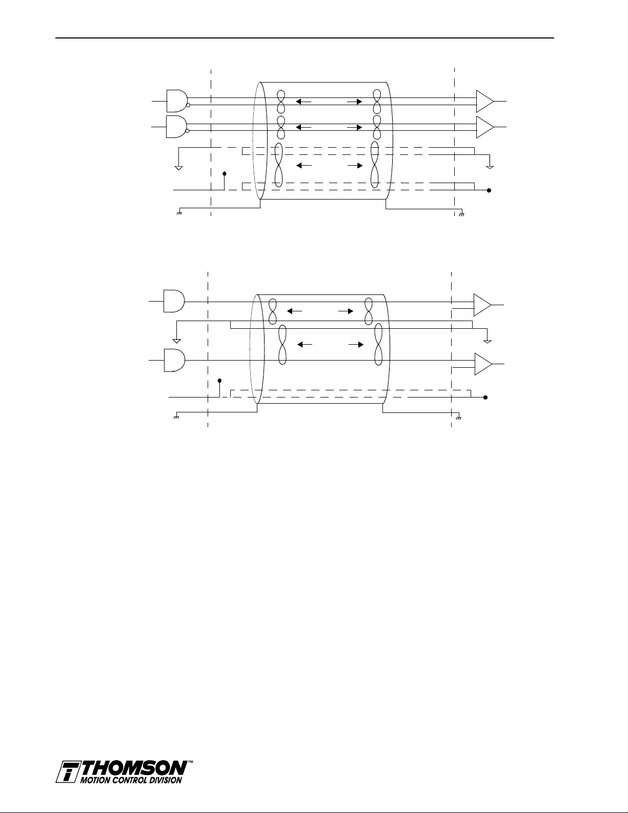
6-24 Interfaces
Intro
USER
ELECTRONICS
J1 Drive
IGURE
F
Intro
6.34
TTL
Differential
Line Drivers
+5V
Supply
Return
+5V
Supply
CW+
CW-
CCW+
CCW-
twisted pair
twisted pair
twisted pair
+5 Volts
For horiz ontal dashed lines, connect only if
J1 sources +5VDC power to user electronics
14
15
16
17
2
4
3
1
5V @ 250 mA
CW+
CW-
CCW+
CCW-
External CW/CCW (Step Up/Step Down) Interface via TTL Differential Line Drivers
+5V
Supply
Return
+5V
Supply
USER
ELECTRONICS
CW
CCW
twisted pair
twisted pair
+5 Volts
Connect only if J1 sources +5VDC power to user electronics.
J1 Drive
14
4
2
16
3
1
5V @ 250 mA
CW+
CW-
CCW+
CCW-
+5VDC
Drive Chassis
+
-
+
-
ECOM
+5VDC
Drive Chassis
+
-
ECOM
+
-
IGURE
F
6.35
External CW/CCW (Step Up/Step Down) Interface via Single-Ended Line Drivers
(not recommended)
J1 Terminal Strip/Breakout Board
A 50-pin terminal strip kit is available for extending the signals from the J1 connector. The kit includes
a 1 meter (3-foot) interface cable, a 50-pin terminal strip and mounting hardware.
Artisan Technology Group - Quality Instrumentation ... Guaranteed | (888) 88-SOURCE | www.artisantg.com
Page 76

6Interfaces
pin 10
pin 11
pin 20
pin 1
J2 – Encoder
Interfaces 6-25
Pin Signal Description Pin Signal Description
Intro
CAUTION
!
1 EPWR Encoder Power 11 I (+) Motor Encoder Input
2 ECOM Encoder Common 12 I (-) Motor Encoder Input
3 EPWR Encoder Power 13 A Hall Effect A
4 ECOM Encoder Common 14 B Hall Effect B
5 EPWR Encoder Power 15 C Hall Effect C
6 ECOM Encoder Common 16 ABS Absolute Position
7 A (+) Motor Encoder Input
8 A (-) Motor Encoder Input
9 B (+) Motor Encoder Input
10 B (-) Motor Encoder Input
Channel A(+)
Channel A(-)
Channel B(+)
Channel B(-)
17 Reserved
18 Reserved
19 TS(+) Thermal Switch (+)
20 TS(-) Thermal Switch (-)
Channel I(+)
Channel I(-)
Ensure that the encoder si gna ls are co nnected properly. Incorrect connection
of the encoder signals wi ll result in improp er rotor positio n, incorrect commutation and/or a runaway motor condition.
Intro
IGURE
F
Intro
IGURE
F
6.36
6.37
Thomson Industries cables are available in various lengths for connecting between J1 and a suitable
controller.
DriveJ2
AM(+)
AM(-)
Motor Encoder Interface Circuit
DriveJ2
A,
B or
C
200
0.1 uF
Hall Effect Sensor Circuit
+5V
1K
MC74HC14F
200
.01uF
1K
1K
220pF
220pF
+
-
AM26LS33
AM
Installation Manual for Models ODM-005, ODM-005i, ODM-010, ODM-010i, ODM-020 and ODM-020i
Artisan Technology Group - Quality Instrumentation ... Guaranteed | (888) 88-SOURCE | www.artisantg.com
Page 77

6-26 Interfaces
T
ABLE
6.21
J2- Motor Encoder Connector Pin-Outs
Motor Encoder Pin Number Description
EPWR J2-1
J2-3
J2-5
ECOM J2-2
J2-4
J2-6
A(+)
A (-)
B(+)
B (-)
I (+)
I (-)
J2-7 (+)
J2-8 (-)
J2-9 (+)
J2-10 (-)
J2-11 (+)
J2-12 (-)
HALL A J2-13 Hall Effect A sensor logic level input. Internally pulled up to +5VDC through
HALL B J2-14 Hall Effect B sensor logic level input. Internally pulled up to +5VDC through
HALL C J2-15 Hall Effect C sensor logic level input. Internally pulled up to +5VDC through
ABS J2-16 Absolute Position used on Thomson Industries motors for commutation.
J2-17
J2-18
TS+
TS–
J2-19
J2-20
a. OMNI LINK software automatically determines the presence or absence of a motor thermal switch signal based
on the motor selected in the Drive Select window.
IGURE
F
6.36
OMNIDRIVE Motor Encoder Connections
Encoder power
Encoder common
Motor Encoder Input Channel A(+) and Channel A(-). Accepts TTL level
signals from a line driver.
Motor Encoder Input Channel B(+) and Channel B(-). Accepts TTL level
signals from a line driver.
Motor Encoder Input Channel I(+) and Channel I(-). Accepts TTL level signals from a line driver. Output pulse occurs once per motor shaft revolution.
a 1 kOhm resistor.
a 1 kOhm resistor.
a 1 kOhm resistor.
Reserved.
Thermal Switch + and Thermal Switch – are a motor overtemperature
a
signal.
Drive
J2-1
EPWR
J2-2
ECOM
J2-3
EPWR
J2-4
ECOM
J2-5
EPWR
J2-6-
ECOM
J2-7
AM+
J2-8-
AM-
J2-9
BM+
J2-10
BM-
J2-11
IM+
J2-12
IM-
ABS
TS+
TS-
J2-13
J2-14
J2-15
J2-16
J2-19
J2-20
HALL A
HALL B
HALL C
NOTES:
1. For encoders with differential Hall ouputs (A+, A-, B+, B-, C+ and C-) connect only the + outputs to the drive.
2. The ABS signal is only available on selected Thomson Industries encoders.
ENCODER
+5V
COM
A+
AB+
BZ+
Z-
1
HALL A
1
HALL B
1
HALL C
2
ABS
THERMOSTAT+
THERMOSTAT-
MOTOR
Artisan Technology Group - Quality Instrumentation ... Guaranteed | (888) 88-SOURCE | www.artisantg.com
Page 78

J2 Terminal Strip/Breakout Board
A 25-pin terminal strip kit is available for extending the encoder signals from the J2 connector. The kit
includes a 3-foot (1 meter) interface cable a 25-pin terminal strip, and mounting hardware.
6Interfaces
J5 – Serial Port
Pin Signal Description Use
1 RCV(+) Receive (+) RS-485 (four wire)
Interfaces 6-27
Intro
2 RCV Receive RS-232
pin 9
pin 5
3XMT Transmit RS-232
4 XMT(+) Transmit (+) RS-485 (four wire)
5 COM +5 VDC Common
6 Reserved
a
pin 6
pin 1
7 RCV(-) Receive (-) RS-485 (four wire)
8 XMT(-) Transmit (-) RS-485 (four wire)
9 Reserved
a. Do
connect any device to J4-6, J5-6, J4-9 or J5-9 except an Thomson Industries TouchPad.
not
1
J5 is 9 pin female D-shell (AMP 205204-4, pins AMP 66506-3) connector. This connector is a serial
interface that allows communication with another OMNIDRIVE , a PC, a terminal, a host computer, a
controller or an optional TouchPad. The shell of the connector is grounded to the chassis for shield
termination.
EXTINT
XMT
IGURE
F
6.38
RECEIVE
RS-232
TRANSMIT
TRANSMIT
ENABLE
RS-485
RCV
XMTXMT+
RCV+
RCV-
RS-232/485 Interface Circu it
The serial interface of the OMNIDRIVE uses the standard NRZ asynchronous serial format, and supports
both the RS-232 and the four wire RS-485 communications standards.
• Standard baud rates include 1200, 2400, 4800, 9600 and 19200 baud. 9600 is the factory
default setting.
• Even, odd, and no parity generation/checking are supported. No parity is the factory default
setting.
• The maximum number of OMNIDRIVEs allowable on an RS-485 bus is 32.
• The maximum length of an RS-232 cable is 15 meters (50 feet).
Installation Manual for Models ODM-005, ODM-005i, ODM-010, ODM-010i, ODM-020 and ODM-020i
Artisan Technology Group - Quality Instrumentation ... Guaranteed | (888) 88-SOURCE | www.artisantg.com
Page 79

6-28 Interfaces
• The maximum length of an RS-485 cable is 1220 meters (4000 feet) with 0.20 mm2
Thomson Industries cables are available in various lengths for connecting to the serial port of an
OMNIDRIVE and a control unit, such as a PC.
(24 AWG) wire.
T
ABLE
6.22
TIP
The shell of the connector is grounded to the chassis for shield termination.
The following table lists the pin-outs for J5.
J5 – Serial Port Connector Pin-Outs
Signal Pin Number Description
RCV (+)
RCV (-)
XMT (+) XMT
(-)
COM J4 - 5 Common serial port interface
RCV J4 - 2 RS-232 receiver input (to drive)
XMT J4 - 3 RS-232 transmitter output (from drive)
not
a. Do
J4 - 1 (+)
J4 - 7 (-)
J4 - 4 (+)
J4 - 8 (-)
J4 - 6 Reserved
J4 - 9 Reserved
connect any device to J4-6, J5-6, J4-9 or J5-9, except an Thomson Industries TouchPad.
RS-485 differential receiver input (to drive)
RS-485 differential transmitter output (from drive)
a
a
Serial Communications Overview
OMNIDRIVEs communicate via a standard NRZ (non-return to zero) asynchronous serial format, which
supports either RS-232 or four wire RS-485. The pin-out arrangement on the drive serial ports provides
self-sensing of the communication standard. To change from RS-232 to four wire RS-485 requires a
simple change of the cable.
In multiple drive installations, a unique address must be assigned to each drive through software. The
factory default drive address is setting is Address 0. All addresses changes are made through OMNI LINK
software selection. Up to 32 (1 through 32) are supported.
TIP
NOTE:
immediate; they are logged but do not become active until
Address and communications settings changes are not
after
the drive
is RESET.
Each drive may be assigned a unique name of up to 32 characters in length; a name is often easier to
remember than the address of a drive. OMNI LINK software automatically associates a drive name with
the correct drive address.
RS-232 Connections
The address of each drive is set using OMNI LINK software. Refer to the OMNILINK on-line Help.
not
Do
connect any device to J5-6 or J5-9 except an Thomson Industries
TouchPad.
Single Axis RS-232 Set Up
A single OMNIDRIVE may be selected using RS-232 communications. After cabling is attached to the
unit and the drive address is assigned, configuration of (i.e., communications with) the unit may proceed.
The following steps outline how to select the communications options:
Artisan Technology Group - Quality Instrumentation ... Guaranteed | (888) 88-SOURCE | www.artisantg.com
Page 80

Intro
Interfaces 6-29
Factory default settings for a OMNIDRIVE are:
•Address 0
• 9600 Baud
• 8 Data, No Parity, 1 Stop bit
The following steps outline how to select the communications options:
1. Connect an RS-232 cable between the computer and a serial connector on the drive (J5).
9-Pin
Male
Drive
J4 or J5
USER
PC
9-Pin
RS-232
9-Pin Male Connector to 9-Pin Female Connector
RS-232 CABLE
9-Pin
Female
IGURE
F
6.39
RCV*
XMT*
COM*
* PC pin-outs
may vary by
manufacturer
USER
PC
25-Pin
RS-232
XMT*
RCV*
COM*
* PC pin-outs
may vary by
manufacturer
2
3
5
9-Pin Male Connector to 25-Pin Female Connector
25-Pin
Female
2
3
7
RS-232 Connection Diagrams
RS-232 CABLE
9-Pin
Male
2
3
5
2
3
5
2
3
5
Drive
J4 or J5
2
3
5
RCV
XMT
COM
Drive Chassis
RCV
XMT
COM
Drive Chassis
2. Verify the computer can communicate with the drive by performing the following:
• Switch drive power to ON
• Start OMNI LINK on the attached PC
• Choose
• Select
• Select
CANCEL
ommunications
C
P
C Set Up
from the Drive Select window
from the menu
from the pull down menu
• Verify the port settings, and if necessary, change them, then choose OK.
• Select
• Select
ommunications
C
R
ead Drive Parameters
from the menu
from the pull down menu
• Choose OK in the Drive Select window.
3. Verify that OMNI LINK reads the drive parameters. If not, refer to “Troubleshooting” on
page 11-3.
Installation Manual for Models ODM-005, ODM-005i, ODM-010, ODM-010i, ODM-020 and ODM-020i
Artisan Technology Group - Quality Instrumentation ... Guaranteed | (888) 88-SOURCE | www.artisantg.com
Page 81

6-30 Interfaces
Intro
Intro
Intro
NOTE:
The Scan Port for Attached Drives option in the Drive Select
window of OMNI LINK will identify any attached drives. If a drive is
identified, but cannot be communicated with, the Baud Rate selection
must be modified.
The cable diagrams provide wiring examples for both 9 pin and 25 pin serial ports from an IBM compatible
personal computer to the drive. RS-232 pin-outs vary between computer manufacturers. Check the hardware reference manual of your machine to ensure correct signal connections between the computer and
the drive.
Four Wire RS-485 Connections
The OMNIDRIVEs use a variation of the RS-485 standard, known as four wire RS-485. Four wire RS485 uses one differential signal for host to drive transmissions, and another differential signal for drive
to host transmissions. (The RS-485 standard specifies a single differential signal for transmissions in both
directions.)
The four wire RS-485 configuration also allows the host to use a RS-422 type interface. Because the host
is driving multiple receivers and receiving from multiple transmitters, RS-422 is limited to multiple axes
connections with 10 or less drives. The figure below summarizes the four wire RS-485, RS-422, and RS485 standards.
Four Wire RS-485
Differential
4 Wires
2 Signal Pairs
1 to 32 Transmitters
1 to 32 Receivers
12 32
RS-422
Differential
4 Wires
2 Signal Pairs
1 Transmitter
1 to 10 Receivers
RS-485 Standard
Differential
2 Wires
1 Signal Pair
1 to 32 Transmitters
1 to 32 Receivers
NOTE:
Not applicable
to OMNIDRIVEs
12 10
12 32
IGURE
F
6.40
RS-485/RS-422 Communication Comparison
Artisan Technology Group - Quality Instrumentation ... Guaranteed | (888) 88-SOURCE | www.artisantg.com
Page 82

Interfaces 6-31
Multiple Axes Four-Wire RS-485 Communications
not
Do
TIP
connect any device to J5-6 or J5-9 except an Thomson Industries
TouchPad.
1. Select a previously unused address (1-32) from OMNI LINK - Drive Set Up.
2. Connect cables between:
• The host computer and the serial port on the initial drive (J5) in the multiple drive configuration.
• The other serial port on the initial drive (J5) and the serial port on the next drive (J5) in the
multiple drive configuration
Flat ribbon cable is not recommended for RS-485 connections.
TIP
3. Verify the communication settings on the computer are correct:
• Start OMNI LINK on the attached PC
• Choose CANCEL from the Drive Select window
• Select C
• Select P
ommunications from the menu
C Set Up from the pull down menu.
• Verify the port settings, and if necessary, change them, then choose OK.
TIP
Address 0 is the preferred add ress for the initial configuration of a dri ve. It forces
the drive to the default communications parameters.
4. Verify the ability to communicate between the computer and the connected drives by:
• Switch drive power to ON
• Select C
• Select R
ommunications from the menu
ead Drive Parameters from the pull down menu
• Select the drive to communicate with from Drive Select window (the drive must have an
address that matches one of the drive addresses in the chain)
• Choose OK in the Drive Select window.
5. Verify that OMNI LINK loads the drive parameters. If not, refer to the troubleshooting section.
6. Repeat the preceding two steps for each additional drive.
Four wire RS-485 connections are shown below. The cable diagram provides a wiring example of a daisy
chain connection in a typical installation A multi-drop cable (Figure 6.41) may also be used.
Multiple Axes RS-232 Communications
Multiple axes systems may be controlled by a computer with an RS-232 serial port. An RS-232 serial
communication port may be converted to four wire RS-485 communication by attaching an RS-232 to
four wire RS-485 converter. The figure below depicts the use of such a device.
Installation Manual for Models ODM-005, ODM-005i, ODM-010, ODM-010i, ODM-020 and ODM-020i
Artisan Technology Group - Quality Instrumentation ... Guaranteed | (888) 88-SOURCE | www.artisantg.com
Page 83

6-32 Interfaces
Intro
HOST
COMPUTER
RS-485
INTERFACE
*RCV*RCV+
*XMT*XMT+
* Pin-outs
may vary by
manufacturer
IGURE
F
6.41
74
1
RCV+ RCV- XMT+
J4
8
XMT-
74
1
RCV+ RCV- XMT+
J5
8
XMT-
74
1
RCV+ RCV- XMT+
J4
Drive 1
Four Wire RS-485 Daisy Chain Connection Diagram
1
74
8
XMT- RCV+ RCV- XMT+
J5
Drive 2
8
XMT-
1
RCV+ RCV- XMT+
.......
74
J4
Drive n
8
XMT-
Artisan Technology Group - Quality Instrumentation ... Guaranteed | (888) 88-SOURCE | www.artisantg.com
Page 84

Power Connections 7-1
HAPTER
C
ABLE
T
7.1
7:
Power Connections
DC bus, single phase AC power and motor connections are provided on the Terminal Block (TB-1).
TB1 – DC Bus and AC Power Terminal Block Connections
Description Identifier Terminal ODM-00 5 and -005i
DC Bus + voltage DC BUS + 1
DC Bus - voltage DC BUS - 2
100-240 VAC input power L1 (Line 1) 3
100-240 VAC input power L2 (Line 2)/
N (Neutral)
Safety (earth) ground 5
R phase power to motor R 6
S phase power to motor S 7
T phase power to motor T 8
Motor case ground 9
ODM-010 and -01 0i
ODM-020 and -02 0i
4
Intro
DANGER
Intro
WARNING
Power Wiring Connection Diagrams for the ODM-005, -005i, -010, -010i, -020 and -020i are
provided on page 5-8. Wiring for the external I/O power is described and depicted in the chapter
“Application and Configuration Examples” on page 8-1
DC bus capacitors may retain hazardous voltages for several minutes after
input power has been remov ed, but will normally disch arge in several seconds.
Measure the DC bus voltage to verify it has reached a safe level each time
power is removed before wo rking o n the dri ve; or w ait for th e time indicated in
the warning on the front of the drive. Failure to observe this precaution could
result in severe bodily injury or loss of life.
Motor power connectors are for assembly purposes only. They should not be
connected or disconnected while the drive is powered.
Installation Manual for Models ODM-005, ODM-005i, ODM-010, ODM-010i, ODM-020 and ODM-020i
Artisan Technology Group - Quality Instrumentation ... Guaranteed | (888) 88-SOURCE | www.artisantg.com
Page 85

7-2 Power Connections
Motor Power Cabling
TB1-6, TB1-7, TB1-8 and TB1-9 are the terminals for connecting the drive to the windings of a motor.
T
ABLE
7.2
Intro
DANGER
TIP
Proper phasing of these outputs relative to the motor terminals is critical.
Double check the connections after wiring the motor.
Table 7.2 lists the drive terminals and typical motor connections. Table 7.3 lists the minimum wire size
for making power wiring connections.
Motor Power Terminals
Motor Phase Signal Description Terminal
R R phase from drive TB1-6
S S phase from drive TB1-7
T T phase from drive TB1-8
Gr ound for the motor case TB1-9
NOTE
: Torque all terminal connections to 1.25 Nm (11.0 lb-in).
Shield Termination of Power Cables
Shielded power cables must be grounded at a minimum of one point for
safety . Failure to ground a sh ielded power cable will resul t in potentially lethal
voltages on the shield and anything connected to it.
Intro
IGURE
F
7.1
Thomson Industries motor power cables are shielded. The power cable is designed to be terminated at
the drive during installation. A small portion of the cable jacket is stripped, which exposes the shield
wires. The exposed area must be clamped at the left front of the drive chassis using the clamp provided
near the bottom. It is critical for EMC performance that the shield wires be clamped against the area of
the chassis which is not painted. This section of the chassis is labeled with the chassis ground symbol.
T
Shield
Cable Jacket
Power cable shield termination clamp on bottom of ODM-005, ODM-010 and ODM-020
Motor Power EMC Shield Connection
Masked area
Artisan Technology Group - Quality Instrumentation ... Guaranteed | (888) 88-SOURCE | www.artisantg.com
Page 86

Power Connections 7-3
T
ABLE
7.3
Motor Power Contact and Wire Size Recommendations
Motor Size
Motor Power Mating
Maximum Contact Size
mm2 (AWG)
a
Minimum Recommended
90°C Power Wire
mm2 (AWG)
2005 through 3016 1.5 (16) 1.5 (16)
4030 4 (12) 1.5 (16)
4050 4 (12) 2.5 (14)
a.
Motor Overload Protection
The drive utilizes solid state motor overload protection which operates:
• within 8 minutes at 200% overload
• within 20 seconds at 600% overload.
Power Supply Protection
The feedback encoder, auxiliary encoder and optional TouchPad are powered by a single internal power
supply. The power supply has a “resettable” fuse that opens at 3 amps and automatically resets itself when
the current falls below 3 amps.There are no internal fuses requiring replacement.
Installation Manual for Models ODM-005, ODM-005i, ODM-010, ODM-010i, ODM-020 and ODM-020i
Artisan Technology Group - Quality Instrumentation ... Guaranteed | (888) 88-SOURCE | www.artisantg.com
Page 87

7-4 Power Connections
Emergency Stop Wiring
An overlapping contactor may be inserted between the motor and the drive for emergency stop purposes.
The contactor must not simply break the motor current, it also must switch a three phase resistive load in
parallel with the motor windings.
The three resistors provide dynamic braking. In addition, they prevent continuous arcing at the main
contacts when breaking DC currents, such as when the motor stalls. Simply breaking the motor current
can result in high voltages due to motor inductance, which will cause prolonged arcing in the contactor.
In extreme cases, the prolonged arcing could result in the contactor catching fire. An overlapping contactor
provides the required timing by engaging the braking contactors before the drive contactors disengage.
Figure 7.2 depicts a contactor installation with resistive loads. Follow these guidelines:
• The resistor values should be one to four times the winding resistance for good braking
performance. Refer to Appendix D, “Dynamic Braking Resistor Selection” for resistor
sizing equations.
• Screen and ground cables should be connected as shown.
• Shields should be unbraided (not a drain wire soldered to the shield).
• Connection lengths should be minimized.
• Safety ground (GND) and shield connections are permanently connected. This is essential
for electrical safety.
• EMC guidelines require connection of the shield at the point where the contactor is
Intro
inserted.
Resistor
Overlapping
Contactor
IGURE
F
7.2
Resistor
Resistor
R
Drive
Unbraided shield
S
T
Grounded terminal or stud
Emergency Stop Contactor Wiring
R
STMotor
GNDGND
Isolated terminal
Enclosure wall
Artisan Technology Group - Quality Instrumentation ... Guaranteed | (888) 88-SOURCE | www.artisantg.com
Page 88

Intro
DANGER
!
Power Connections 7-5
AC Power Cabling
The ODM-005, -005i, -010, -010i -020 and -020i drives require single phase, 100 to 240 VAC rms power
with an input frequency of 47 - 63 Hz. “Power” on page E-6 lists the output power characteristics of the
drives. The AC input supplies power to the motor. Alternatively, the drive may be powered by an external
DC power source. In either case, an external power source must provide input power to the I/O.
TB1-3, TB1-4 and TB1-5 are the single phase AC input power terminals for the ODM-005, 005i, -010, -010i, -020 and -020i.
The user is responsible for conforming with all applicable local, national and
international code s. Wiri ng prac tices , ground ing, dis conn ects a nd ove rcur rent
protection are of part icular importance. F ailure to observe thi s precaution could
result in severe bodily injury or loss of life.
.
T
T
ABLE
ABLE
Intro
WARNING
!
Intro
CAUTION
!
7.4
7.5
High voltage may be present on the termi nals of th e OMNIDRI VE. Ensure th at
the drive is connected to a safety (earth) ground.
not
Do
tin (solder) the exposed lead s on cables. Solder contracts over time and
may loosen the connection.
The inputs to the main (logic and motor supply) and the auxiliary (logic supply only) power sources are
separated. This permits independent powering of the control power and the motor power. This dual power
sourcing is useful for troubleshooting and diagnostics.
TB1 - AC Power Terminals
Signal Description Terminal
L1 100 to 240 Volts AC Line 1 input power. TB1-3
L2/N 100 to 240 Volts AC Neutral. TB1-4
Safety (earth) ground TB1-5
NOTE: Torque all terminal connections to 1.25 Nm (11.0 lb-in).
AC Input Power Sizing Requirements
Drive Model Input Current Inrush
Current
ODM-005 or
ODM-005i
5 A AC
rms
75 A peak 5 A 1.5 (16) 1 kVA
Fuse
Size
Wire Size
1
mm (AWG)
Tr ansformer Size
min
a
100 kVA
max
Installation Manual for Models ODM-005, ODM-005i, ODM-010, ODM-010i, ODM-020 and ODM-020i
Artisan Technology Group - Quality Instrumentation ... Guaranteed | (888) 88-SOURCE | www.artisantg.com
Page 89

7-6 Power Connections
ODM-010 or
ODM-010i
ODM-020 or
ODM-020i
1. In the United States, the National Electric al Cod e (NEC), specif ies that fu ses mus t be sele cted
based on the motor full load amperage (FLA), which is not to be confused with the drive input
current. The largest fu se allow ed under an y circum stances is four tim es the moto r FLA. Theref ore
the largest fuse permissib le for use with the OMNIDRIVE is four times the motor rated conti nuous
current (converted to an RMS value). The Digital Servo Drive has been evaluated and listed by
Underwriters Laboratori es Inc. with fuses sized as four time s the con tinuou s outpu t current of th e
drives (FLA), according to UL 508C.
In almost all cases fuses selected to match the drive input current rating will meet the NEC
requirements and provide the full drive capabilities. Dual element, time delay (slow acting) fuses
should be used to avoid nuisance trips during the inrush current of power initialization. The fuse
sizes listed are recommended values, but local regulations must be determined and adhered to.
The OMNIDRIVE utilizes solid state motor short circuit protection rated as follows:
Suitable for use on a circuit capable of del ivering not more than 5000 RMS symmetrical Amp eres,
240 Volts maximum.
Suitable for use on a circui t capable of delivering not more than 2 00,000 RMS symmetrical Amperes,
240 Volts maximum, when protected by high interrupting capacity, current limiting fuses (Class
CC, G, J, L, R, T).
a. Technical Note Number 1 details Transformer Sizing requirements for a variety of applications.
9 A. AC
18 A. AC
Short Circuit Current Rating with No Fuse Restrictions:
Short Circuit Current Rating with Fuse Restrictions:
100 A peak 10 A 2.5 (14) 2 kVA
rms
100 A peak 20 A 4.0 (12) 4 kVA
rms
min
min
100 kVA
max
100 kVA
max
Intro
DANGER
!
Intro
WARNING
!
Intro
CAUTION
!
DC Bus
TB1-1 and TB1-2 are the DC Bus connections for an external shunt.
DC bus capacitors m ay retain hazardous voltag es af ter input power has been
removed, but wil l normally discha rge in several sec onds. Before workin g on the
drive, measure the DC bu s voltag e to verify it has reac hed a safe level or wai t
the full time interval listed on the warning on the front of the drive. Failure to
observe this precaution could result in severe bodily injury or loss of life.
External shunt resistors connect directly to the power bus. For safety
reasons, external shunt resistors must be enclosed.
not
Do
connect an external I/O power supply to th e DC Bus. The DC+ a nd DC-
terminals connect directly to the power bus of the drive.
Artisan Technology Group - Quality Instrumentation ... Guaranteed | (888) 88-SOURCE | www.artisantg.com
Page 90

Application and Configuration Examples 8-1
HAPTER
C
8:
Application and Configuration Examples
This section explains how to install and verify the OMNIDRIVE for various modes of operation. The
procedures verify the installation by:
How to modify the units of measurement for OMNI LINK displays is explained on page 8-35.
Analog Control
The OMNIDRIVE can be set up as an analog drive in either the Velocity or Torque mode by making the
hardware connections and performing the software setup and tuning described below. The connection
diagram depicts the minimum hardware necessary. Interfacing the drive to an external controller requires
similar circuitry from the controller to J1. Instructions are provided to configure the drive using a PC with
OMNI LINK software, but the optional TouchPad also may be used.
• Showing how the power and logic wiring is connected.
• Selecting the Operation Mode setup for the drive.
• Tuning the drive for a particular motor type and size.
• Verifying the basic functionality of the drive and motor combination.
Hardware Set Up
Make the connections described below and shown in the figure.
1. Connect a ±10VDC power source between J1-22 and J1-23 (ANALOG CMND +/-) to provide
the analog speed or torque command.
2. Connect an RS-232 cable between the serial port on the PC and the J4 connector on the drive. A
simple 3 wire cable is depicted in the figure below.
3. Connect a Motor/Feedback cable from the motor to the J2 connector on the drive.
4. Connect a Power cable from the motor to TB1 (terminals R, S, T and ) on the drive.
5. Connect a jumper wire with a toggle switch between the following pins:
• J1-20 (ENABLE) and J1-26 (I/O PWR)
• J1-21 (FAULT RESET) and J1-26 (I/O PWR).
These connections provide manual control for enabling or disabling the drive and resetting faults.
The figure below shows the jumper, including normally open toggle switches.
6. Connect an external 12 to 24 VDC poweer source for powering I/O to J1-5 (I/O PWR)
and J1-6 (I/O COM).
7. Connect the drive to a single phase 100/240 VAC, 50/60 Hz power source.
Connection Diagram
Configuration
Carefully check all connections before entering these parameters.
1. Switch the AC Power to ON and verify:
Installation Manual for Models ODM-005, ODM-005i, ODM-010, ODM-010i, ODM-020 and ODM-020i
Artisan Technology Group - Quality Instrumentation ... Guaranteed | (888) 88-SOURCE | www.artisantg.com
Page 91

8-2 Application and Configuration Examples
Intro
DRIVE
J5
XMT
2 RCV
RCV
3 XMT
COM
5 COM
J1
26 I/O PWR
Close to ENABLE Drive
Close to RESET Fault
±10VDC
External I/O
12-24 VDC
Power Source
20 ENABLE
21 FAULT
RESET
22 CMND+
23 CMND-
5 I/O PWR
6 I/O COM
J2
Motor
Encoder
TB1
Phase R 6
Phase S 7
Phase T 8
Mtr Gnd 9
L1 3
L2/N 4
Gnd 5
100-240 VAC
50/60 Hz
Single Phase
Power Source
IGURE
F
8.1
Analog Controller Connection Diagram
• Status LED is green. Refer to "Status indicator" on page 10-1 for an explanation of the display codes.
2. Start OMNI LINK on the PC.
3. Choose
4. Select
Cancel
P
from the Drive Select dialog box.
C Set Up
from the Communications menu in OMNI LINK to display the personal com-
puter’s communication settings.
5. Verify the communications port settings of the PC match those of the drive.
• If the settings are correct, select OK in the Port – Settings dialog box.
• If the settings are different, correct the Port – Settings to allow communications with the
drive.
Factory default communications Port – Settings for the drive are:
– Baud Rate:
– Data Bits:
– Parity:
– Stop Bits:
– Serial Port:
9600
8
None
1
COM1
Refer to the section “RS-232 Communication Test” on page 11-6 for troubleshooting instructions.
6. Select
R
ead Drive Parameters
from the Communications menu.
7. Verify the Drive Name and Address are correct for the drive that is being addressed.
8. Choose OK to load the drive parameters.
TIP
A motor must be selected for the parameters to load.
9. If the message box appears that a motor must be selected, select OK. The Drive Set Up window
is displayed with Motor Model selection parameter active. The motor may be selected from the
Artisan Technology Group - Quality Instrumentation ... Guaranteed | (888) 88-SOURCE | www.artisantg.com
Page 92

Application and Configuration Examples 8-3
drop down box. If this message box does not appear, the motor displayed in the Motor Model
box was previously selected.
10. Select or verify the correct motor model number from the drop down Motor Model list.
TIP
TIP
11. If a message advises that the drive must be reset, choose
Yes
.
12. Select the Operation Mode parameters for the drive:
Velocity Mode Settings Torque Mode Settings
A
nalog Velocity Input
13. Choose
14. Choose the
Close
Drive
15. Enter appropriate S
Tuning
Do
Input. If the drive is set to Torque mode, continue with the Operation section
below.
Do
OMNIDRIVE will
not
attempt to T une a d rive with the Command mode set for Analog Torque
not
attempt to Auto Tune systems that have gravitational effects. The
not
1. Choose the
Tuning
as the Operation Mode
Analog Torque Input
to exit the Drive Set Up window.
P
arameters
cale
hold initial position.
icon from the Drive window and then select the
and O
values for the input.
ffset
command icon from the Drive window. The drive must be configured in
Velocity mode for tuning to be effective.
as the Operation Mode
Analog
tab.
Intro
WARNING
2. Select
utoTune
A
from the Tuning mode group.
3. Select the appropriate values for the following Auto Tune commands:
•
Distance
•
Step Current.
and
4. Select the appropriate entry for the Motor Direction:
•
BiDirectional
•
Forward Only
•
Reverse Only
,
or
.
5. Close the toggle switch between J1-26 and J1-20 to enable the drive.
Rotating motor shafts c an cause extensive damage and injury . Mo tors must be
properly guarded during testing and installation.
6. Choose S
from the Tuning window. The drive powers the motor shaft for a short period and
tart
then motion will cease. Then OMNI LINK displays the calculated gains and disables the drive.
7. Open the switch between J1-26 and J1-20 to disable the drive.
8. Choose N
ormal Drive Operation
from the Tuning window.
9. Choose
Installation Manual for Models ODM-005, ODM-005i, ODM-010, ODM-010i, ODM-020 and ODM-020i
Artisan Technology Group - Quality Instrumentation ... Guaranteed | (888) 88-SOURCE | www.artisantg.com
to exit the Tuning windows.
Close
Page 93

8-4 Application and Configuration Examples
10. Close any open windows or dialogs.
Operation
The drive is now configured as an Analog Controller in either the velocity or torque mode.
• The current loop is compensated properly for the selected motor.
• The servo parameters have been setup with an unloaded motor.
• The motor speed or current is commanded through the analog input.
The firmware saves the parameters in EEPROM memory. Thus the drive can be power cycled and, after
power-up, will use the parameters selected in the steps above.
When motion is required:
1. Close the switch between J1-26 and J1-20 to enable the drive.
Artisan Technology Group - Quality Instrumentation ... Guaranteed | (888) 88-SOURCE | www.artisantg.com
Page 94

8Application and Configuration Examples
Preset Controller
The OMNIDRIVE can be set up as a preset controller in the Velocity or Torque mode by making the
connections described below. Three discrete digital inputs provide the programmable speed or torque
control. Up to eight different preset speed or torque settings can be selected by using the three digital
inputs in various binary combinations, as shown in the table below. The connection diagram depicts the
minimum hardware necessary. Interfacing the drive to a controller requires similar circuitry from the
controller to J1. Instructions are provided to configure the drive using a PC with OMNI LINK software,
but the optional TouchPad also may be used.
Application and Configuration Examples 8-5
T
ABLE
8.1
Preset Binary Inputs
Inputs
C B A Description
Preset 0
Preset 1
Preset 2
Preset 3
Preset 4
Preset 5
Preset 6
Preset 7
1. A preset input signal that is OFF is inactive, which means no current flows through the optocoupler.
2. A preset input signal that is ON is active, which means current flows through the optocoupler.
0 0 0 Preset 0 is a preprogrammed speed or current.
All inputs are OFF
0 0 1 Preset 1 is a preprogrammed speed or current.
Only Preset Select A input is ON
0 1 0 Preset 2 is a preprogrammed speed or current.
Only Preset Select B input is ON
0 1 1 Preset 3 is a preprogrammed speed or current.
Preset Select A and Preset Select B are ON
1 0 0 Preset 4 is a preprogrammed speed or current.
Only Preset Select C input is ON
1 0 1 Preset 5 is a preprogrammed speed or current.
Preset Select A and Preset Select C are ON
1 1 0 Preset 6 is a preprogrammed speed or current.
Preset Select B and Preset Select C are ON
1 1 1 Preset 7 is a preprogrammed speed or current.
All Preset Select inputs are ON
1
.
2
.
2
.
2
.
2
.
Hardware Set Up
Make the connections described below and shown in Figure 8.2.
1. Connect an RS-232 cable between the serial port on the PC and the J4 connector on the drive.
A simple 3 wire cable is depicted in the figure below.
2
.
2
.
2
.
2. Connect a Motor/Feedback cable from the motor to the J2 connector on the drive.
3. Connect a Power cable from the motor to TB1 (terminals R, S, T and ) on the drive.
4. Connect a jumper wire with a toggle switch between the following pins:
• J1-20 (ENABLE) and J1-26 (I/O PWR)
• J1-32 (INPUT1) and J1-26 (I/O PWR)
• J1-33 (INPUT2) and J1-26 (I/O PWR)
• J1-34 (INPUT3) and J1-26 (I/O PWR)
• Connect a switch between J1-21 (FAULT RESET) and J1-26 (I/O PWR).
These connections provide manual control for enabling or disabling the drive and resetting faults. The
figure below shows the jumper, including normally open toggle switches.
Installation Manual for Models ODM-005, ODM-005i, ODM-010, ODM-010i, ODM-020 and ODM-020i
Artisan Technology Group - Quality Instrumentation ... Guaranteed | (888) 88-SOURCE | www.artisantg.com
Page 95

8-6 Application and Configuration Examples
1. Connectan external 12 to 24 VDC power supply for powering I/O to J1-5 (I/O PWR) and J1-6
(I/O COM).
2. Connect the drive to a single phase 100/240 VAC, 50/60 Hz power source.
Connection Diagram
Intro
DRIVE
J5
XMT
2 RCV
RCV
3 XMT
COM
5 COM
J1
26 I/O PWR
Close to ENABLE Drive
Close to RESET Fault
Close to Turn ON
Close to Turn ON
Close to Turn ON
External I/O
12-24 VDC
Power Source
20 ENABLE
21 FAULT
RESET
32 INPUT1
33 INPUT2
34 INPUT3
5 I/O PWR
6 I/O COM
J2
Motor
Encoder
TB1
Phase R 6
Phase S 7
Phase T 8
Mtr Gnd 9
L1 3
L2/N 4
Gnd 5
100-240 VAC
50/50 Hz
Single Phase
Power Source
IGURE
F
8.2
Preset Controller Connection Diagram
Configuration
Carefully check all connections before entering these parameters.
1. Switch the AC Power to ON and verify:
• Status LED is green. Refer to "Status indicator" on page 10-1 for an explanation of the display codes.
2. Start OMNI LINK on the PC.
3. Choose
4. Select
Cancel
P
puter’s communication settings
5. Verify the communications port settings of the PC match those of the drive.
• If the settings are correct, select OK in the Port – Settings dialog box.
• If the settings are different, correct the Port – Settings to allow communications with the
drive.
Factory default communications Port – Settings for the drive are:
– Baud Rate:
– Data Bits:
– Parity:
– Stop Bits:
– Serial Port:
from the Drive Select dialog box.
C Set Up
None
from the Communications menu in OMNI LINK to display the personal com-
9600
8
1
COM1
Artisan Technology Group - Quality Instrumentation ... Guaranteed | (888) 88-SOURCE | www.artisantg.com
Page 96

Application and Configuration Examples 8-7
Refer to the section “RS-232 Communication Test” on page 11-6 for troubleshooting instructions.
6. Select
Read Drive P
arameters
from the Communications menu.
7. Verify the Drive Name and Address are correct for the drive that is being addressed.
8. Choose OK to load the drive parameters.
TIP
A motor must be selected for the parameters to load.
9. If the message box appears that a motor must be selected, select OK. The Drive Setup window is
displayed with Motor Model selection parameter active. The motor may be selected from the
drop down box. If this message box does not appear, the motor displayed in the Motor Model
box was previously selected.
10. Select or verify the correct motor model number from the drop down Motor Model list.
11. If a message advises that the drive must be reset, choose
Yes
,
12. Select the Operation Mode parameter for the drive:
Velocity Mode Settings Torque Mode Settings
Preset Velocities
13. Choose
Close
14. Choose the
tab.
set
as the Operation Mode
from the D
Drive P
arameters
Preset Torques
rive Setup window.
command icon from the Drive window and then select the
as the Operation Mode
15. Enter the appropriate parameters for the Command mode in which the drive will operate:
Velocity Mode Settings Torque Mode Settings
Enter the appropriate velocity value for each speed
required
Enter the appropriate current value for each torque
required
Pre-
Up to eight presets (0-7) may be programmed.
16. Choose
to exit the Drive Parameters window.
Close
17. Verify the Status indicator is green.
18. Select the
I/O C
onfiguration
command icon from the Drive window.
19. Assign one of the three Preset Selects (A, B and C) to each of the Digital Input Assignments. For
example, the following selects three presets:
•
In
•
Inp
•
Inpu
put 1
ut 2
t 3
to
Preset Select A
to
Preset Select B
to
Preset Select C
The presets provide up to eight binary combinations of speed or current. Unassigned preset inputs should
be set to
Not Assigned
20. Verify all Digital Output Assignments are
21. Choose
Close
, which forces an OFF state.
Not Assigned
to exit the I/O Configuration window.
.
Installation Manual for Models ODM-005, ODM-005i, ODM-010, ODM-010i, ODM-020 and ODM-020i
Artisan Technology Group - Quality Instrumentation ... Guaranteed | (888) 88-SOURCE | www.artisantg.com
Page 97

8-8 Application and Configuration Examples
TIP
TIP
Tuning
Do
If the drive is set to Torque mode, continue with the Operation section below.
Do
OMNIDRIVE will
not
attempt to T une a drive with the Command mode set for Preset T orques .
not
attempt to Auto Tune systems that have gravitational effects. The
not
hold initial position.
1. Choose the
command icon from the Drive window. The drive must be configured in
Tuning
Velocity mode for tuning to be effective.
2. Select
utoTune
A
from the Tuning mode group.
3. Select the appropriate values for the following Auto Tune commands:
•
•
Distanc
St
and
e
ep Current.
4. Select the appropriate entry for the Motor Direction:
•
B
•
Forw
•
Re
iDirectional
ard Only
verse Only
,
or
.
5. Close the toggle switch between J1-26 and J1-20 to enable the drive.
Intro
WARNING
Rotating motor shafts c an cause extensive damage and injury . Mo tors must be
properly guarded during testing and installation.
6. Choose
from the Tuning window. The drive powers the motor shaft for a short period and
tart
S
then motion will cease. Then OMNI LINK displays the calculated gains and disables the drive.
7. Choose
ormal Drive Operation
N
from the Tuning window.
8. Open the switch between J1-26 and J1-20 to disable the drive.
9. Choose
to exit the Tuning window.
C
lose
10. Verify the Status indicator is green.
11. Close any open windows or dialog boxes.
Operation
The drive is now configured as a Preset Controller in Velocity or Torque mode.
• The servo parameters have been setup with the unloaded motor.
• The motor speed or current is controlled through the digital inputs.
The firmware saves the parameters in EEPROM memory. Thus the drive can be power cycled and, after
power-up, will use the parameters selected in the steps above.
When motion is required:
1. Close the switch between J1-26 and J1-20 to enable the drive.
2. Close any of the switches for INPUT1, INPUT2 or INPUT3 to run the drive at the programmed
preset speed or torque.
Artisan Technology Group - Quality Instrumentation ... Guaranteed | (888) 88-SOURCE | www.artisantg.com
Page 98

8Application and Configuration Examples
Position Follower (Master Encoder)
The OMNIDRIVE can be electronically geared to a master incremental encoder generating quadrature
encoder signals by making the hardware connections and performing the software setup and tuning
described below. The connection diagram depicts the minimum hardware necessary. Interfacing the drive
to an external controller requires similar circuitry from the controller to J1. Instructions are provided to
configure the drive using a PC with OMNI LINK software, but the optional TouchPad also may be used.
Hardware Set Up
Make the connections described below and shown in Figure 8.3.
1. Connect an RS-232 cable between the serial port on the PC and the J4 connector on the
OMNIDRIVE. A simple 3 wire cable is depicted in the figure below.
2. Connect a Motor/Feedback cable from the motor to the J2 connector on the drive.
3. Connect a Power cable from the motor to TB1 (terminals R, S, T and ) on the drive.
4. Connect the Master Encoder to the drive as shown in the diagram.
Application and Configuration Examples 8-9
5. Connect a jumper wire with a switches between the following pins:
• J1-20 (ENABLE) and J1-26 (I/O PWR)
• J1-32 (INPUT1) and J1-26 (I/O PWR)
• J1-21 (FAULT RESET) and J1-26 (I/O PWR).
These connections provide manual control for enabling or disabling the drive and resetting faults.
The figure below shows the jumper, including normally open toggle switches.
6. Connect an external 12 to 24 VDC power source for powering I/O to J1-5 (I/O PWR) and J1-6
(I/O COM).
7. Connect the drive to a single phase 100/240 VAC, 50/60 Hz power source.
Installation Manual for Models ODM-005, ODM-005i, ODM-010, ODM-010i, ODM-020 and ODM-020i
Artisan Technology Group - Quality Instrumentation ... Guaranteed | (888) 88-SOURCE | www.artisantg.com
Page 99

8-10 Application and Configuration Examples
Intro
Connection Diagram
XMT
RCV
COM
Master
Encoder
Close to ENABLE Drive
Close to RESET Fault
Close to Follow
External I/O
12-24 VDC
Power Source
J5
2 RCV
3 XMT
5 COM
J1
1
1 +5V
2 5V COM
14 AX+
15 AX16 BX+
17 BX18 IX+
19 IX20 ENABLE
21 FAULT
RESET
26 I/O PWR
32 INPUT1
5 I/O PWR
6 I/O COM
DRIVE
J2
Motor
Encoder
TB1
Phase R 6
Phase S 7
Phase T 8
Mtr Gnd 9
L1 3
L2/N 4
Gnd 5
100-240 VAC
50/60 Hz
Single Phase
Power Source
IGURE
F
8.3
Note 1. Refer to Figure 6.23 - Figure 6.30 for additional details on the Control Interface Cable.
Position Follower (Master Encoder) Connection Diagram
Configuration
Carefully check all connections before entering these parameters.
1. Switch the AC Power to ON and verify:
• Status LED is green. Refer to "Status indicator" on page 10-1 for an explanation of the display codes.
2. Start OMNI LINK on the PC.
3. Choose
4. Select
Cancel
P
puter’s communication settings.
5. Verify the communications port settings of the PC match those of the drive.
• If the settings are correct, select OK in the Port – Settings dialog box.
• If the settings are different, correct the Port – Settings to allow communications with the
drive.
Factory default communications Port – Settings for the drive are:
– Baud Rate:
from the Drive Select dialog box.
C Set Up
from the Communications menu in OMNI LINK to display the personal com-
9600
Artisan Technology Group - Quality Instrumentation ... Guaranteed | (888) 88-SOURCE | www.artisantg.com
Page 100

Application and Configuration Examples 8-11
TIP
– Data Bits:
– Parity:
– Stop Bits:
– Serial Port:
8
None
1
COM1
Refer to the section “RS-232 Communication Test” on page 11-6 for troubleshooting instructions.
6. Select
ead Drive Parameters
R
from the Communications menu.
7. Verify the Drive Name and Address are correct for the drive that is being addressed.
8. Choose OK to load the drive parameters.
A motor must be selected for the parameters to load.
9. If the message box appears that a motor must be selected, select OK. The Drive Setup window is
displayed with Motor Model selection parameter active. The motor may be selected from the
drop down box. If this message box does not appear, the motor displayed in the Motor Model
box was previously selected.
10. Select or verify the correct motor model number from the drop down Motor Model list.
11. If a message advises that the drive must be reset, choose
12. Select
Follower: Master E
ncoder
as the Operation Mode for the drive.
Yes
,
13. Choose
14. Choose the
from the Drive Setup window.
Close
Drive P
arameter
command icon from the Drive window, then select the
Follower
tab.
15. Enter an appropriate
ear Ratio
G
as the Follower Input. The default Gear Ratio is 1:1 (motor
encoder pulses:master pulses). If a Gear Ratio of 3:1 is entered, the motor is moved 3 encoder
pulses for every incoming master pulse.
16. Choose
to exit the Drive Parameters window.
Close
17. Verify the Status indicator is green.
18. Select the
I/O C
onfiguration
command icon from the Drive Window.
19. Select an appropriate digital input from the pull-down lists available as Digital Input Assignments in the I/O Configuration window.
For example:
•
Follower Enable
•
Not Assigned
•
Not Assigned
20. Choose
Close
as Input 1
as Inputs 2 through 3.
as Outputs 1 through 2.
to exit the I/O Configuration window.
21. Verify the Status indicator is green.
Installation Manual for Models ODM-005, ODM-005i, ODM-010, ODM-010i, ODM-020 and ODM-020i
Artisan Technology Group - Quality Instrumentation ... Guaranteed | (888) 88-SOURCE | www.artisantg.com
 Loading...