

LDK 5301LDK 5301
LDK 5301LDK 5301
LDK 5301
1.5 inch Viewfinder
User’s Guide
3922 496 48971 St.01

Für diese Unterlage behalten wir uns
alle Rechte vor (Gemäß DIN 34).
Technische Änderungen im Zuge der
Weiterentwicklung vorbehalten.
Copyright
FCC Class A Statement
Declaration of Conformity
Copying of this document and giving
it to others, and the use or communication of the contents thereof,
are forbidden without express authority. Offenders are liable to the
payment of damages. All rights are
reserved in the event of the grant of
a patent or the registration of a utility
model or design. Liable to technical
alterations in the course of further
development.
Toute communication ou reproduction de ce document, toute exploitation ou communication de son
contenu sont interdites, sauf autorisation expresse. Tout manquement à cette règle est illicite et
expose son auteur au versement de
dommages et intérêts. Tous nos
droits sont réservés pour le cas de la
délivrance d'un modèle d'utilité. Sous
réserve de modification au cours de
l'évolution technique.
© Thomson Multimedia Broadcast Solutions 2002
We, Thomson Broadcast Solutions Nederland B.V., Kapittelweg 10, 4827 HG Breda, The Netherlands declare under
our sole responsibility that this product is in compliance with the following standards:
EN60065
EN55103-1
EN55103-2
following the provisions of:
a. the Safety Directives 73/23//EEC and 93/68/EEC
b. the EMC Directives 89/336/EEC and 93/68/EEC
: Safety
: EMC (Emission)
: EMC (Immunity)
This product generates, uses, and can radiate radio frequency energy and if not installed and used in accordance with
the instructions, may cause interference to radio communications.
It has been tested and found to comply with the limits for a class A computing device pursuant to Subpart J of part 15
of FCC rules, which are designed to provide reasonable protection against such interference when operated in a commercial environment.
Operation of this product in a residential area is likely to cause interference in which case the user at his own expense
will be required to take whatever measures may be required to correct the interference.

02.30.5 LDK 5301 User's Guide 1.5 Inch Viewfinder 1-1
LDK 5301
1.5 inch Viewfinder
User's Guide
The 1.5 Inch Viewfinder (LDK 5301) is a viewfinder for use with LDK 100 /200 series cameras.
Contents
About This Manual ............................................1-2
Installation .........................................................1-3
Operation ..........................................................1-7
Connectors and Cables ................................. 1-10
Adjustments ................................................... 1-11
Electrical Drawings ......................................... 2-1
Block Diagram...................................................2-2
VF board 1 ........................................................2-3
VF board 2 ........................................................2-7
LED board ...................................................... 2-11
Mechanical Exploded Views ..........................3-1
1.5" Viewfinder assy .........................................3-2
1.5" V.F Housing assy ......................................3-3
1.5" V.F. Magnifier assy ....................................3-4
1.5" V.F. Tube assy...........................................3-5
Microphone clamp assy ....................................3-7
Parts Lists ........................................................4-1

1-2 LDK 5301 User's Guide 1.5 Inch Viewfinder 02.30.5
About This Manual
Purpose of this manual
The purpose of this manual is to present a global
description of how to operate the viewfinder. Consult
the Operator's manual of your camera as required
during and after the installation process.
This manual is an integral part of the service policy.
It ensures that you will be able to install your viewfinder
to meet the requirements of your environment. The
manual provides first line service information so that
suitably qualified service personnel can detect and
repair faults, normally by module replacement.
Because of the complexity of some of the
components, second line service can only be carried
out at the specially equipped service centres and
information concerning second line maintenance is
not supplied in this manual.
Intended audience
The manual is intended as a guide to those with a
working knowledge of camera systems and
installation techniques. The first line detection and
repair of faults requires a general knowledge of test
and measurement techniques. The guide is so
designed that it can be used as wel to the viewfinder,
as wel a simple procedural guide to those who wish
to setup and start shooting immediately, and as a
reference work to be consulted as required during
the long life of the viewfinder.
Service policy
The LDK5301 is a sophisticated viewfinder containing
state-of-the-art electronic components which are
designed to provide long-life operation without the
need for maintenance. With this in mind, the service
policy of Thomson Multimedia Broadcast Solutions
endeavours to ensure that help will be quickly on
hand in the unlikely event of anything going wrong.
The guiding principles of the Thomson Multimedia
Broadcast Solutions first line maintenance philosophy
are speed and cost effectiveness. First line
maintenance is dedicated to keeping your viewfinder
operational, despite a fault, by replacement boards
and the replacement of minor mechanical parts by
the user.
CAUTION
Without additional protection the LDK5301
is protected according to safety
specification EN60529 up to level IPX3
(spraying water). Exposure to splashing or
jetting water can result in harmful effects.
Package contents
The following items are included in the standard
LDK5301 box:
- 1.5 Inch viewfinder (LDK 5301)
- Set of additional supplies
- User's Guide
Optional accessories
- Wide angle eyepiece (LDK 5390/00)
- Left eye adaptor (LDK 5390/10)
Packing/Unpacking
Inspect the shipping container for evidence of damage
immediately after receipt. If the shipping container or
cushioning material is damaged, it should be kept
until the contents of the shipment have been checked
for completeness and the units have been checked
mechanically and electrically.
The contents of the shipment should be checked
against the packing list. If the contents are incomplete,
if there is mechanical damage or defect, or if the units
do not perform correctly when unpacked, notify your
Thomson Multimedia Broadcast Solutions sales or
service centre within eight days. If the shipping
container shows signs of damage or stress, notify the
carrier as well.
If a unit is being returned to Thomson Multimedia
Broadcast Solutions for servicing, try to use the
containers and materials of the original packaging.
Attach a tag indicating the type of service required,
return address, model number, full serial number and
the return number which will be supplied by your
Thomson Multimedia Broadcast Solutions service
centre.
If the original packing can no longer be used, the
following general instructions should be used for
repacking with commercially available materials:
a. Wrap unit in heavy paper or plastic.
b. Use strong shipping container.
c. Use a layer of shock-absorbing material around all
sides of the unit to provide firm cushioning and
prevent movement inside container.
d. Seal shipping container securely.
e. Mark shipping container FRAGILE to ensure
careful handling.
Section 2: Electrical drawings
Section 3: Mechanical Exploded Views
Section 4: Parts Lists
02.30.5 LDK 5301 User's Guide 1.5 Inch Viewfinder 1-3
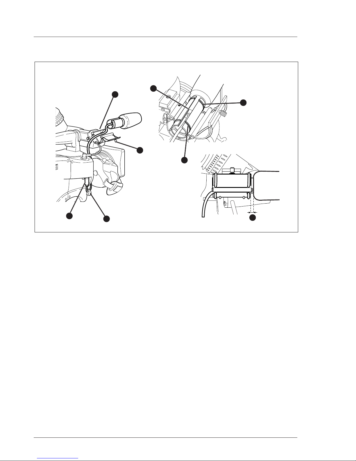
Installation
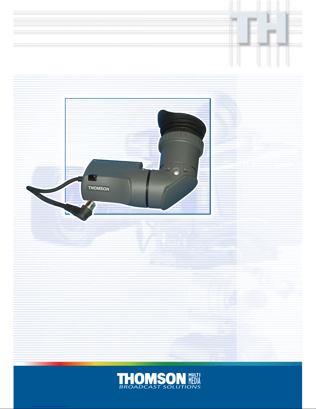
Positioning the 1.5-inch viewfinderMounting the 1.5-inch viewfinder and
microphone holder
1
2
1
2
3
45
4
5
6
3
To mount the 1.5-inch viewfinder proceed as follows:
a. Loosen locking ring (1) of viewfinder support
bracket (2) at the front of the camera handle. (As
seen from the rear of the camera, turning the
locking ring counterclockwise moves it towards
the handle.)
b. Slide the viewfinder onto the viewfinder support
bracket.
c. Tighten the locking ring (1) by turning it clockwise
(as seen from rear) so that the viewfinder is
mounted securely to the support.
d. Connect the viewfinder cable to the viewfinder
connector socket (6) at the top right of the camera.
e. Slide the microphone holder (4) onto the
viewfinder and secure with the knurled screw (5).
CAUTION
Always fit the microphone holder (4) as it
functions as a safety stop for the viewfinder.
f. To improve the comfort of the skin contact when
using the viewfinder, fit the eye piece cover (3) to
the rubber eyepiece. Spare eye piece covers
(3922 405 00461) are available at your Thomson
Multimedia Broadcast Solutions representative.
The horizontal position of the viewfinder can be
adjusted as follows to suit your requirements:
a. Loosen the locking ring (1). (As seen from the
rear of the camera, turning the locking ring
counterclockwise moves it towards the handle.)
b. Slide the viewfinder horizontally along the rail to
the desired position.
c. Tighten the locking ring (1) by turning clockwise.
The dioptre hood and eyepiece of the viewfinder can
be rotated vertically.
The viewfinder can be positioned backwards and
forwards along the camera axis. Loosen the support
bracket round bar retaining lever (2) and slide the
round bar (3) forwards or backwards. When the
desired position is reached tighten the support bracket
round bar retaining lever (2) again.
To use the viewfinder at a distance press the button
(4) below or above the eyepiece tube and swing it
free of the associated clip (5). The display can now
be seen from further away.
1-4 LDK 5301 User's Guide 1.5 Inch Viewfinder 02.30.5
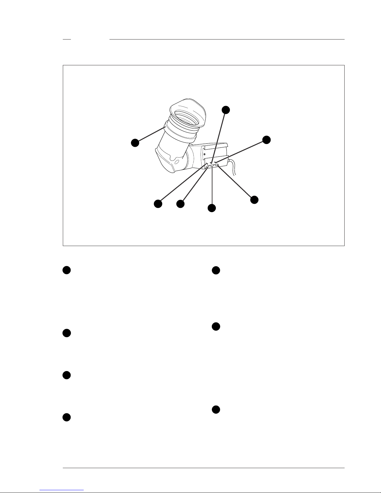
If you regularly use the viewfinder at a distance, for
example, when you use the camera in the hand-held
position, it is recommended that you fit the optionally
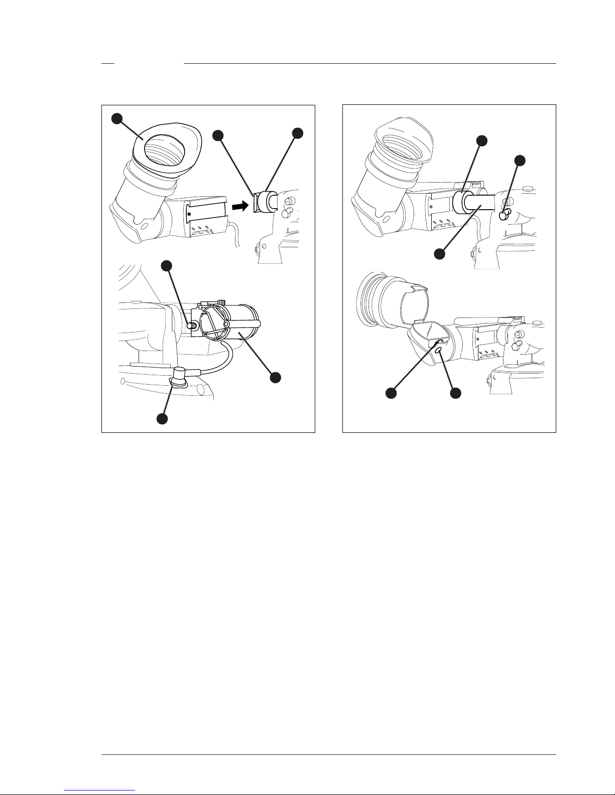
available wide angle eyepiece (LDK 5390/00).
To fit the wide angle eyepiece proceed as follows:
a. Hold the eyepiece (1) securely.
b. Press the button (2) below the eyepiece tube and
swing it free of the button clip (3).
c. Press the button (4) above the eyepiece tube
and remove the eyepiece.
d. Fit the wide angle eyepiece (1) to the two clips (3)
ensuring that they both click into place.
Wide angle eyepiece
2
3
4
1
A left eye adapter is optionally available (LDK 5390/
10) to allow the viewfinder to be used with the left
eye.
Before mounting the viewfinder onto the camera,
attach the left eye adapter (1) to the viewfinder and
secure it using the screw (2). Do not forget to mount
the microphone support bracket (3) at the end of the
left eye adapter.
Left eye adapter
1
2
3
02.30.5 LDK 5301 User's Guide 1.5 Inch Viewfinder 1-5
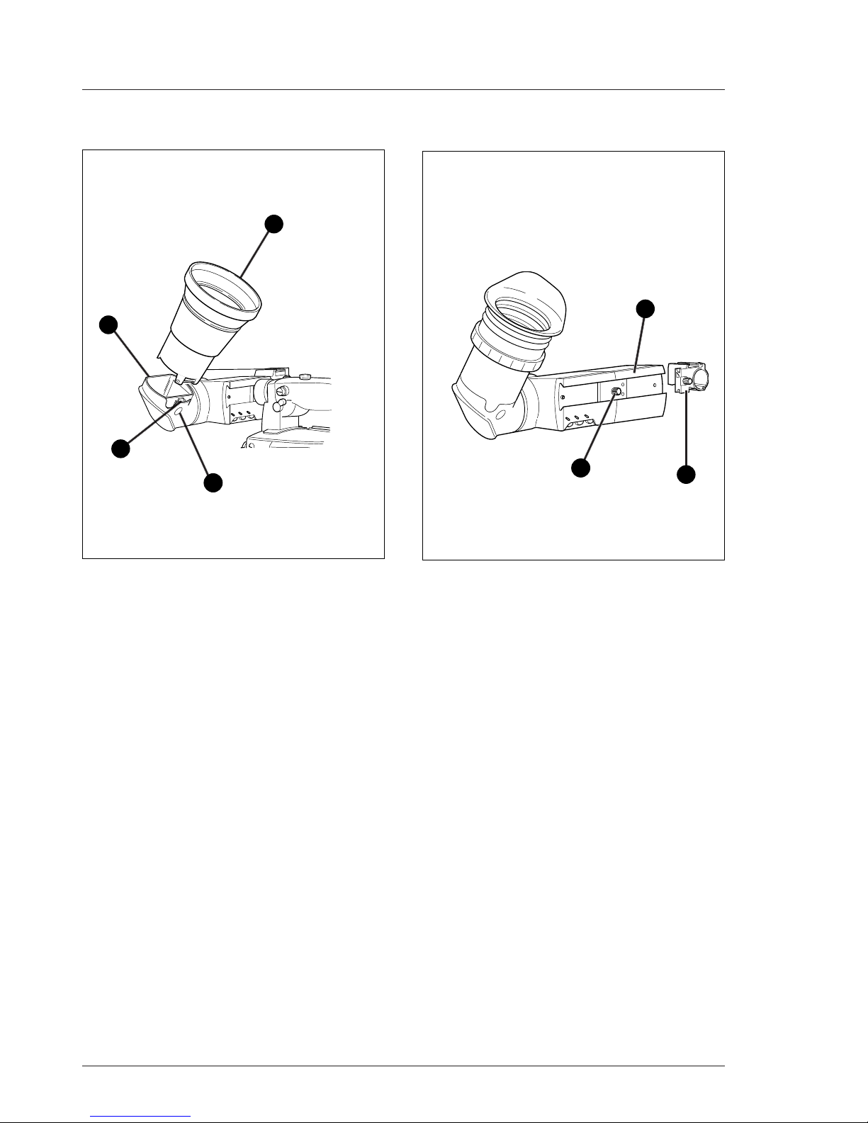
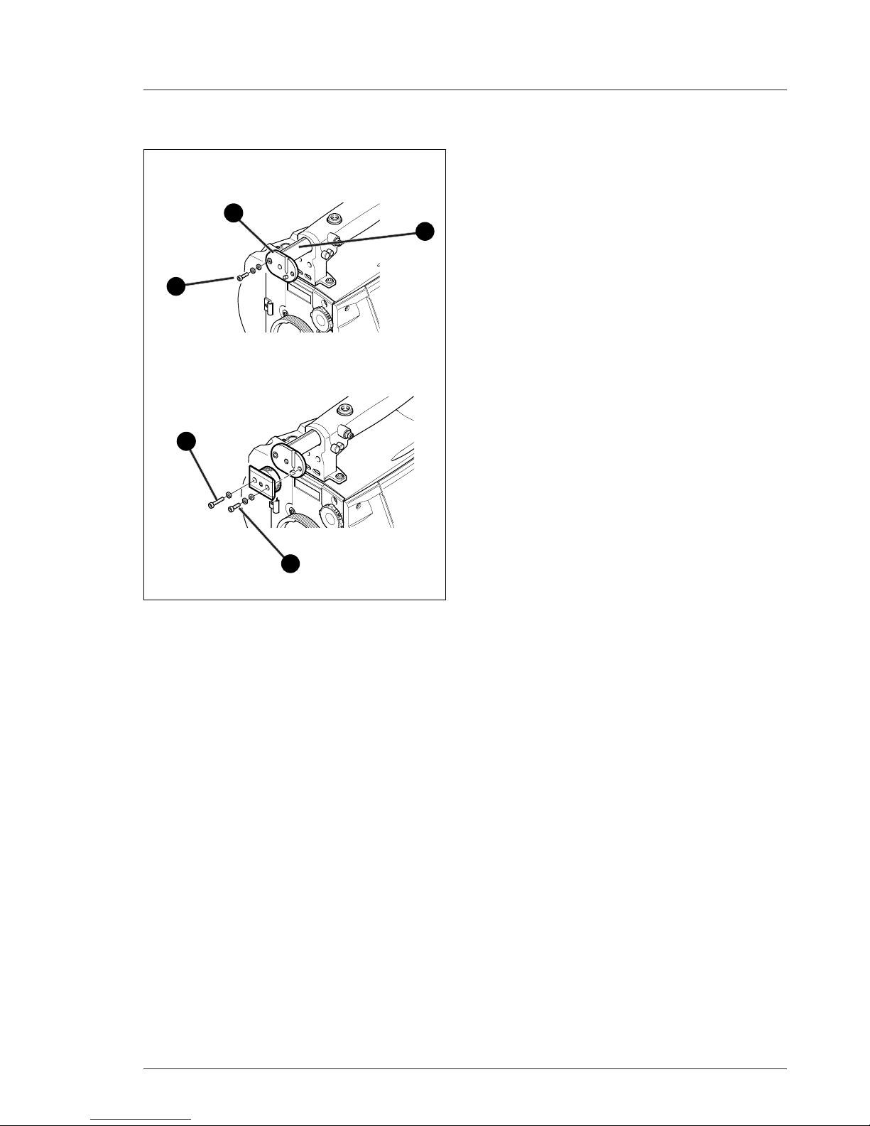
When wearing headphones it may be necessary to
move the viewfinder further to the left to obtain a
more comfortable viewing position. A right eye
adapter (6) is supplied for this purpose. Mount the
right eye adapter as follows:
a. Remove the viewfinder from the support bracket.
b. Unscrew and remove the two screws (7) that hold
the bracket in place.
c. Attach the adapter (6) to the end of the sliding
tube (8) so that it protrudes to the right (as seen
from the front) ensuring that the pins fit snugly
into the slots.
d. Use the short screw (9) and the washers supplied
with the adapter to secure it to the left hole (as
seen from the front) of the sliding bar (8).
e. Attach the support bracket to the adapter ensuring
that the pins fit snugly (if necessary turn locking
ring to move it away from the adapter).
f. Use the long screw (10) supplied with the adapter
and a washer in the left screw hole to secure the
bracket.
g. Use one of the screws (7) and the washer removed
at the start to completely secure the bracket.
h. Remount the viewfinder.
6
7
8
9
10
Right eye adaptor
1-6 LDK 5301 User's Guide 1.5 Inch Viewfinder 02.30.5
2
3
4
1
Microphone
To attach the optional microphone (AJ MC700) to the
camera proceed as follows:
a. Open the microphone holder by unscrewing the
knurled screw (1) of the microphone support
bracket (2) on the viewfinder and open.
b. Slide the microphone into the split tube until the
microphone shoulder reaches the mark (5) in the
tube.
c. Place the tube with the microphone into the
holder with the split facing upwards.
d. Ensure that the rubber supports at the back and
front of the holder fit into the rims (6)around the
tube.
e. Close the holder and tighten the knurled screw at
the top.
f. Connect the microphone cable to audio connector
(3) (mic) on the right side of the camera.
g. Place the microphone cable into the top clip at the
front of the camera and into clip (4) at the side of
the camera.(Pull and twist clip (4) to open it.)
Other microphones with a diameter of 21mm can
also be used, however, ensure that the phantom
power and the sensitivity of the input that match
that type of microphone are correctly selected in
the camera systems menu. Refer to Section 6 for
more information on selecting the audio inputs and
controlling the audio level.
Note:
· When longer microphones are used, it is not
necessary to place them in the split tube.
· For optimum operation, the microphone should
be mounted as straight as possible.
· Don’t allow the wind hood to touch the holder (7)
as this reduces the damping effect.
· By placing the split facing upwards, the
microphone cable does not touch the holder thus
avoiding mechanical pick-up.
· The microphone can also be connected to the
rear of the Triax adapter where a switch selects
the input. Refer to Operator's Guide Triax adaptor
for more information on connecting the
microphone to the rear connector.
5
6
7
6
02.30.5 LDK 5301 User's Guide 1.5 Inch Viewfinder 1-7
Operation
1
2
3
4
5
7
6
Zebra switch
This switch disables (OFF position) or enables the
zebra pattern in the viewfinder which indicates high
video levels. Values for the zebra function are
selected in the VF menu. (The zebra pattern is
switched off when the skin view is on.)
Option switch
This switch is included on the viewfinder to allow
future features to be incorporated.
Brightness control
Use this rotary control to adjust the brightness of the
viewfinder display to suit your needs.
Contrast control
Use this rotary control to adjust the contrast of the
viewfinder display to suit your needs.
Crispening control
This rotary control adjusts the sharpness of the
picture displayed in the viewfinder. Reduce the
crispening for a better picture when the gain is set to
+++.
Tally switch
The tally switch is used to control the tally indicators
at the front of the viewfinder and at the rear of the
carrying handle.
When this switch is set to the ON position, the tally
indicators light when the camera is on-air. When this
switch is set to the OFF position, the tally indicators
do not light when the camera is on-air.
Dioptre
The dioptre of the viewfinder can be adjusted to suit
your eyesight by turning the dioptre ring. The range
of the dioptre is +3 to -3.
1
2
3
4
5
6
7
1-8 LDK 5301 User's Guide 1.5 Inch Viewfinder 02.30.5
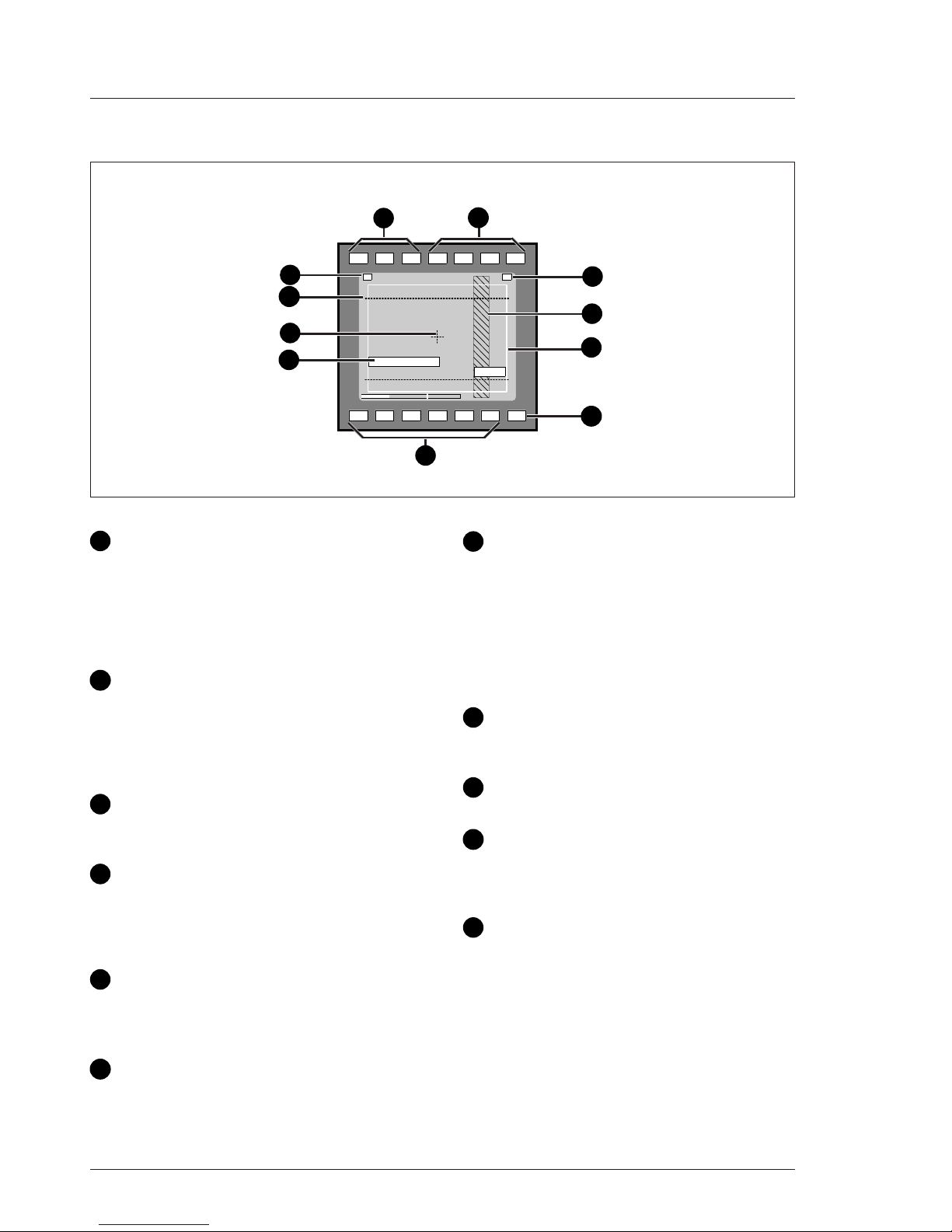
Indicators
ND/RE
BATT
TAPE
REC
++
+
-
!
AW2AW1
FL
7.55.63.2
4
5
10
2
1
3
7
9
11
Gain indicators
The gain indicators in the viewfinder light as follows:
- Gain is - (-3 or -6dB)
+ Gain is + (+6, +9, +12 or +18dB)
++ Gain is ++ (+9, +12,+18 or +24dB)
+ and ++ Gain is +++ (+30 or +36dB)[FT]
(+30, +36 or 42dB)[IT]
Top indicators
REC lights when the camera is on-air.
TAPE lights when the studio ISO signal is received.
BATT lights if the supply voltage is less than 11V.
ND/RE lights when an ND optical filter or the lens
range extender is selected.
Iris indication
Indicates the value of the iris opening (when enabled
in the VF menu).
Zebra pattern
This diagonal line pattern warns the operator that the
area affected has risen above a predetermined level
of the full scale video exposure value. Level and
contrast are selected in the VF menu.
Safe area marker
The safe area marker indicates an area that
represents 80% of the whole viewfinder picture area.
This is the minimum area seen on a TV-set.
Non standard indicator
The non-standard video settings indicator (!) lights
when exposure is not set to nominal. It also lights
when black stretch or extended iris is on.
White Balance indicators
The white balance indicators light as follows:
3,2 - preset temperature of 3200K is selected
5,6 - preset temperature of 5600K is selected
7,5 - preset temperature of 7500K is selected
FL - memory for fluorescent light is selected
AW1 - memory 1 is selected
AW2 - memory 2 is selected
None of these indicators light if AWC is selected.
Message box
The display time of this information message box is
set by the Info time item of the VF menu.
Centre marker
This cross marks the centre of the picture.
Cadre marker (only switchable cameras)
These dotted white lines show the limits of a 4:3
picture in the 16:9 mode, or the limits of a 16:9 picture
in the 4:3 mode.
Zoom indication
Indicates the degree to which the lens has been
zoomed in or out if this feature is supported by the
lens. It shows 50 if not supported.
1
2
3
4
5
6
7
8
9
10
11
8
6
02.30.5 LDK 5301 User's Guide 1.5 Inch Viewfinder 1-9
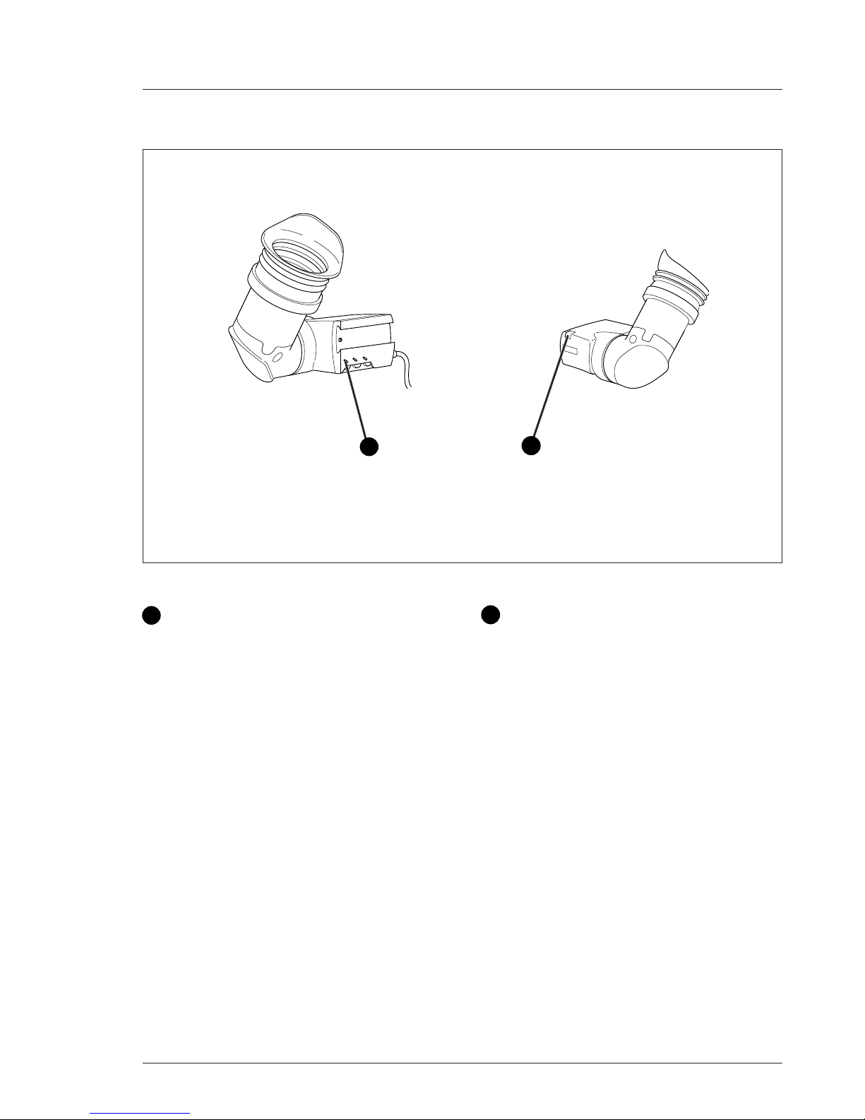
Monitoring Functions
1
2
1
2
Tally switch
The tally switch is used to control the tally indicators
at the front of the viewfinder and at the rear of the
carrying handle.
When this switch is set to the ON position, the tally
indicators light when the camera is on-air.
When this switch is set to the OFF position, the tally
indicators do not light when the camera is on-air.
Tally indicators (red)
The red tally indicators at the front of the viewfinder
and at the rear of the carrying handle light to indicate
that the camera is on-air. They do not light when the
camera is on-air if the tally switch is set to the OFF
position.
1-10 LDK 5301 User's Guide 1.5 Inch Viewfinder 02.30.5
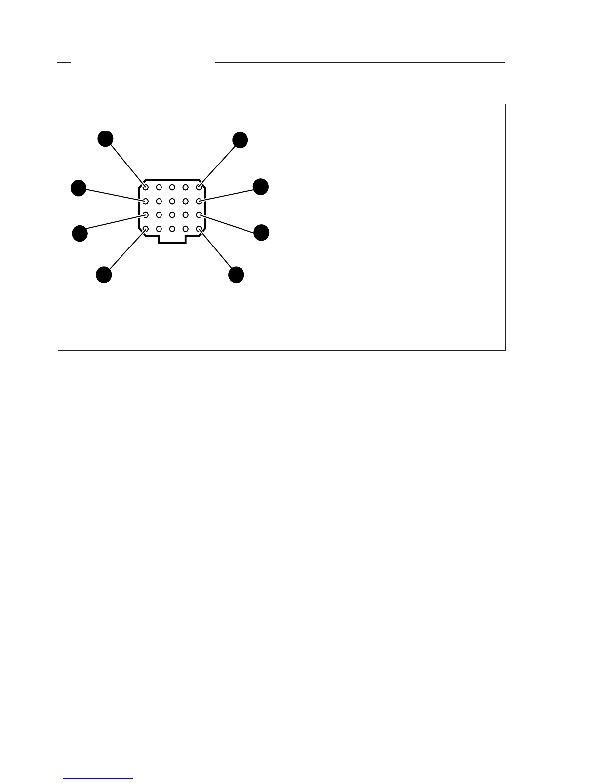
Connectors and Cables
1. -80V
2. n.c.
3. GND
4. INTN-D
5. vf ext video
6. n.c.
7. vf video ret
8. SDA-D
9. SCL-D
10. vf ext video ret
11. GND
12. vf video
13. Pb vf ret
14. Pr vf ret
15. GND
16. +batt
17. +batt
18. Pb vf
19. Pr vf
20. shield
20-pin male; connector view
Viewfinder connector
1
6
5
10
11
16
20
15
02.30.5 LDK 5301 User's Guide 1.5 Inch Viewfinder 1-11
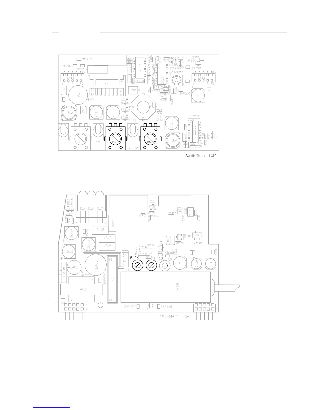
Adjustments
Turn R4 (constrast) anti-clokwise and R5 (brightness) to mid position.
Adjust R413 (preset) for just visible background
Adjust focus control R426 by means of wave signal to maximise simultaneous visibility of horizontal
and vertical lines in the centre of the picture.
1-12 LDK 5301 User's Guide 1.5 Inch Viewfinder 02.30.5
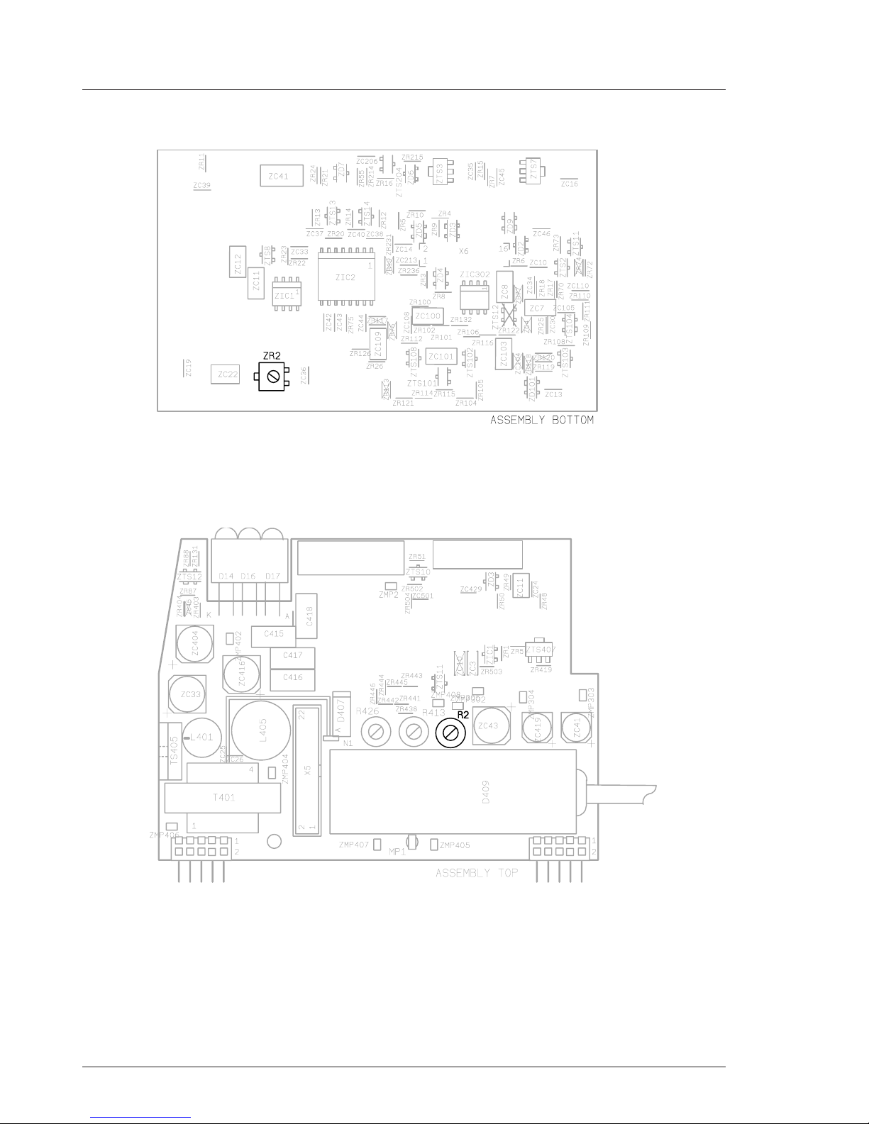
Adjust geometry, picture dimensions and optimum.
Horizontal amplitude by means of ZR2.
Vertical amplitude by means of R2
Rotating by means of the deflection coil and centrering by means of the centring magnets

Electrical Drawings User's Guide LDK 5301 1.5 inch Viewfinder 2-1
Section 2
Electrical Drawings
Contents
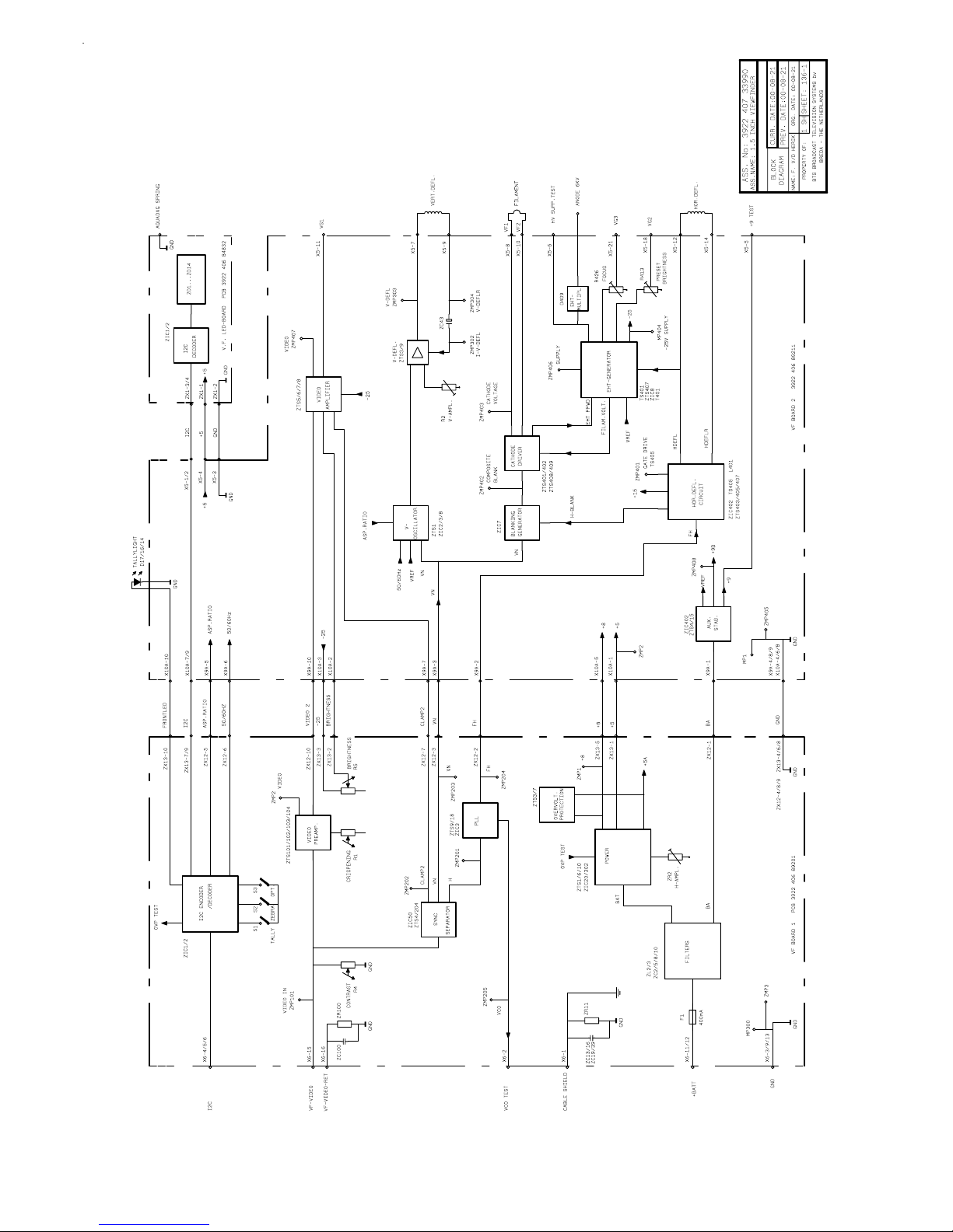
Block Diagram ...................................................2-2
VF board 1 ........................................................2-3
VF board 2 ........................................................2-7
LED board .......................................................2-11
2-2 User's Guide LDK 5301 1.5 inch Viewfinder Electrical Drawings
 Loading...