

THOMSON LDK 5481, LDK 4700 User Manual
LDK 5481 + LDK 4700
User’s Guide
SD DigiLink camera system
3922 496 30541 April 2007 v4.0

LDK 5481 + LDK 4700 User’s Guide ii
Declaration of Conformity
We, Grass Valley Nederland B.V., Kapittelweg 10, 4827 HG Breda, The Netherlands, declare
under our sole responsibility that this product is in compliance with the following standards:
- EN60950-1 : Safety
- EN55103-1: EMC (Emission)
- EN55103-2: EMC (Immunity)
following the provisions of:
a. the Safety Directives 73/23//EEC and 93/68/EEC
b. the EMC Directives 89/336/EEC and 93/68/EEC
FCC Class A Statement
This product generates, uses, and can radiate radio frequency energy and if not installed and
used in accordance with the instructions, may cause interference to radio communications.
It has been tested and found to comply with the limits for a class A digital device pursuant to
part 15 of the FCC rules, which are designed to provide reasonable protection against such
interference when operated in a commercial environment.
Operation of this product in a residential area is likely to cause interference in which case the
user at his own expense will be required to take whatever measures may be required to correct
the interference.
Copyright
Copyright Grass Valley Nederland B.V. 2007. Copying of this document and giving it to others,
and the use or communication of the contents thereof, are forbidden without express authority.
Offenders are liable to the payment of damages. All rights are reserved in the event of the grant
of a patent or the registration of a utility model or design. Liable to technical alterations in the
course of further development.
Trademarks
Grass Valley and Infinity are trademarks of Grass Valley, Inc. All other tradenames referenced are
service marks, trademarks, or registered trademarks of their respective companies.
Website
Visit the Grass Valley public website to download the latest user’s guide updates and additional
information about your broadcast product:
www.thomsongrassvalley.com

LDK 5481 + LDK 4700 User’s Guide i
Table of contents
Chapter 1 – DigiLink system
1.1 Introduction . . . . . . . . . . . . . . . . . . . . . . . . . . . . . . . . . . . . . . . . . . . . . . . . . . . . . . . . 1-1
1.2 Accessories . . . . . . . . . . . . . . . . . . . . . . . . . . . . . . . . . . . . . . . . . . . . . . . . . . . . . . . . 1-1
1.3 Compatibility . . . . . . . . . . . . . . . . . . . . . . . . . . . . . . . . . . . . . . . . . . . . . . . . . . . . . . . 1-2
1.4 Configurations . . . . . . . . . . . . . . . . . . . . . . . . . . . . . . . . . . . . . . . . . . . . . . . . . . . . . . 1-3
1.4.1 Digilink system SDI coax configuration . . . . . . . . . . . . . . . . . . . . . . . . . . . . . . 1-3
1.4.2 DigiLink system multicore configuration . . . . . . . . . . . . . . . . . . . . . . . . . . . . . 1-4
1.4.3 Stand alone SDI coax configuration . . . . . . . . . . . . . . . . . . . . . . . . . . . . . . . . . 1-4
1.4.4 Stand alone multicore configuration . . . . . . . . . . . . . . . . . . . . . . . . . . . . . . . . 1-5
1.5 Intercom . . . . . . . . . . . . . . . . . . . . . . . . . . . . . . . . . . . . . . . . . . . . . . . . . . . . . . . . . . . 1-6
Chapter 2 – LDK 5481 DigiLink Adapter
2.1 Specifications. . . . . . . . . . . . . . . . . . . . . . . . . . . . . . . . . . . . . . . . . . . . . . . . . . . . . . . 2-4
2.2 Dimensions . . . . . . . . . . . . . . . . . . . . . . . . . . . . . . . . . . . . . . . . . . . . . . . . . . . . . . . . 2-4
2.3 Compatibility . . . . . . . . . . . . . . . . . . . . . . . . . . . . . . . . . . . . . . . . . . . . . . . . . . . . . . . 2-5
2.4 Controls . . . . . . . . . . . . . . . . . . . . . . . . . . . . . . . . . . . . . . . . . . . . . . . . . . . . . . . . . . . 2-5
2.4.1 Powering the camera. . . . . . . . . . . . . . . . . . . . . . . . . . . . . . . . . . . . . . . . . . . . 2-5
2.5 Attaching the LDK 5481 adapter to a camera head. . . . . . . . . . . . . . . . . . . . . . . . . 2-6
2.6 Mounting a script board . . . . . . . . . . . . . . . . . . . . . . . . . . . . . . . . . . . . . . . . . . . . . . 2-7
2.7 Adapter connectors . . . . . . . . . . . . . . . . . . . . . . . . . . . . . . . . . . . . . . . . . . . . . . . . . . 2-8
2.7.1 SDI video output connector . . . . . . . . . . . . . . . . . . . . . . . . . . . . . . . . . . . . . . . 2-8
2.7.2 SDI video input connector . . . . . . . . . . . . . . . . . . . . . . . . . . . . . . . . . . . . . . . . 2-9
2.7.3 Multicore connector. . . . . . . . . . . . . . . . . . . . . . . . . . . . . . . . . . . . . . . . . . . . . 2-9
2.7.4 Video signal (VF) output connector . . . . . . . . . . . . . . . . . . . . . . . . . . . . . . . . 2-10
2.7.5 Video signal (CVBS) output connector . . . . . . . . . . . . . . . . . . . . . . . . . . . . . . 2-10
2.7.6 Intercom headset connector . . . . . . . . . . . . . . . . . . . . . . . . . . . . . . . . . . . . . 2-10
2.7.7 LCP / Fibre power connector . . . . . . . . . . . . . . . . . . . . . . . . . . . . . . . . . . . . . 2-11
2.7.8 DC power output socket . . . . . . . . . . . . . . . . . . . . . . . . . . . . . . . . . . . . . . . . 2-11
2.7.9 DC power input socket . . . . . . . . . . . . . . . . . . . . . . . . . . . . . . . . . . . . . . . . . 2-12
2.7.10 Script light power supply socket . . . . . . . . . . . . . . . . . . . . . . . . . . . . . . . . . . 2-12
2.8 Install menu . . . . . . . . . . . . . . . . . . . . . . . . . . . . . . . . . . . . . . . . . . . . . . . . . . . . . . . 2-13
Chapter 3 – LDK 4700 base unit
3.1 Installation information. . . . . . . . . . . . . . . . . . . . . . . . . . . . . . . . . . . . . . . . . . . . . . . 3-4
3.1.1 Ventilation . . . . . . . . . . . . . . . . . . . . . . . . . . . . . . . . . . . . . . . . . . . . . . . . . . . . 3-4
3.1.2 Rack mounting instructions . . . . . . . . . . . . . . . . . . . . . . . . . . . . . . . . . . . . . . . 3-4
3.1.3 Installation notices . . . . . . . . . . . . . . . . . . . . . . . . . . . . . . . . . . . . . . . . . . . . . . 3-5
3.1.4 Mains power supply chord . . . . . . . . . . . . . . . . . . . . . . . . . . . . . . . . . . . . . . . 3-5
3.2 Specifications. . . . . . . . . . . . . . . . . . . . . . . . . . . . . . . . . . . . . . . . . . . . . . . . . . . . . . . 3-7
3.3 Dimensions . . . . . . . . . . . . . . . . . . . . . . . . . . . . . . . . . . . . . . . . . . . . . . . . . . . . . . . . 3-8
3.4 Controls and indicators . . . . . . . . . . . . . . . . . . . . . . . . . . . . . . . . . . . . . . . . . . . . . . . 3-9
3.4.1 Powering the base unit . . . . . . . . . . . . . . . . . . . . . . . . . . . . . . . . . . . . . . . . . . 3-9
3.4.2 Indicators . . . . . . . . . . . . . . . . . . . . . . . . . . . . . . . . . . . . . . . . . . . . . . . . . . . . . 3-9
3.4.3 Set-up items . . . . . . . . . . . . . . . . . . . . . . . . . . . . . . . . . . . . . . . . . . . . . . . . . . 3-9

LDK 5481 + LDK 4700 User’s Guide ii
3.5 Connecting the studio signalling . . . . . . . . . . . . . . . . . . . . . . . . . . . . . . . . . . . . . . 3-11
3.5.1 Call and On-air signals . . . . . . . . . . . . . . . . . . . . . . . . . . . . . . . . . . . . . . . . . . 3-11
3.6 DigiLink base unit connectors. . . . . . . . . . . . . . . . . . . . . . . . . . . . . . . . . . . . . . . . . 3-13
3.6.1 Setup switches . . . . . . . . . . . . . . . . . . . . . . . . . . . . . . . . . . . . . . . . . . . . . . . 3-13
3.6.2 Audio out connector. . . . . . . . . . . . . . . . . . . . . . . . . . . . . . . . . . . . . . . . . . . . 3-14
3.6.3 Signalling / Intercom / Auxiliary connector . . . . . . . . . . . . . . . . . . . . . . . . . . . 3-14
3.6.4 External video input connector . . . . . . . . . . . . . . . . . . . . . . . . . . . . . . . . . . . 3-14
3.6.5 Reference input connector . . . . . . . . . . . . . . . . . . . . . . . . . . . . . . . . . . . . . . 3-14
3.6.6 Teleprompter input connector . . . . . . . . . . . . . . . . . . . . . . . . . . . . . . . . . . . . 3-15
3.6.7 Y, Pr, Pb output connectors. . . . . . . . . . . . . . . . . . . . . . . . . . . . . . . . . . . . . . 3-15
3.6.8 SDI Camera connectors . . . . . . . . . . . . . . . . . . . . . . . . . . . . . . . . . . . . . . . . . 3-15
3.6.9 CVBS output connector . . . . . . . . . . . . . . . . . . . . . . . . . . . . . . . . . . . . . . . . . 3-16
3.6.10 SDI video output connectors . . . . . . . . . . . . . . . . . . . . . . . . . . . . . . . . . . . . . 3-16
3.6.11 RS-232/RS-422 control connector . . . . . . . . . . . . . . . . . . . . . . . . . . . . . . . . . 3-16
3.6.12 Mains power supply input socket . . . . . . . . . . . . . . . . . . . . . . . . . . . . . . . . . 3-17
3.6.13 Auxiliary connector. . . . . . . . . . . . . . . . . . . . . . . . . . . . . . . . . . . . . . . . . . . . . 3-17
3.6.14 DC power output connector . . . . . . . . . . . . . . . . . . . . . . . . . . . . . . . . . . . . . 3-18
3.6.15 Multicore connector. . . . . . . . . . . . . . . . . . . . . . . . . . . . . . . . . . . . . . . . . . . . 3-18

v4.0
LDK 5481 + LDK 4700 User’s Guide | DigiLink system 1-1
Chapter 1
DigiLink system
1.1 Introduction
The DigiLink system consists of a camera adapter (LDK 5481) and a base unit (LDK 4700) for
use with Grass Valley standard definition (SD) camera heads. The system features digital signal
processing and digital transmission of all signals between the camera head and base unit to
ensure there is no loss of quality.
As well as delivering high-quality 10-bit SDI video and audio of CD quality, the bidirectional
digital transmission system carries teleprompter, external video for viewfinder, intercom,
control and tally signals, embedded genlock and private data signals. All these signals are
embedded in the SDI signal streams.
The flexible system configuration makes DigiLink the ideal companion for LDK cameras in
many environments. Depending on the application and cable lengths needed, the system can
utilize low-cost coax cables or existing multicore cables.
Typical applications for DigiLink include educational use or small studios such as local TV
stations, continuity or announcement studios. It is also ideal for use in conference and
parliamentary systems or in high-end surveillance. The camera with DigiLink adapter can also
operate as a stand-alone unit by using its VTR output.
1.2 Accessories
The following DigiLink accessories are available:
RS-232 powerline cable LDK 8120/02, LDK 8120/10, LDK8120/25
RS-422 powerline cable LDK 8121/02, LDK 8120/10, LDK8120/25
Headset dynamic XLR-5 with double muff LDK 8111/37
DC power supply 100W 2-out LDK 5901/00
Local Control Panel LCP 100 LDK 5201
Operational Control Panel OCP 400 LDK 4640/10

v4.0
LDK 5481 + LDK 4700 User’s Guide | DigiLink system 1-2
1.3 Compatibility
If you wish to control your camera locally, you can connect an OCP 400 to the RS-232
connector of the camera. When an OCP 400 panel is used with the DigiLink system, C2IP
functions (e.g. file management) are not supported by the system.
☞
Note
The LDK 5481 adapter is backwards compatible with existing LDK 5480 breakout boxes and
can be connected to them as described in the LDK 5480 User’s Guide.
v4.0
LDK 5481 + LDK 4700 User’s Guide | DigiLink system 1-3
1.4 Configurations
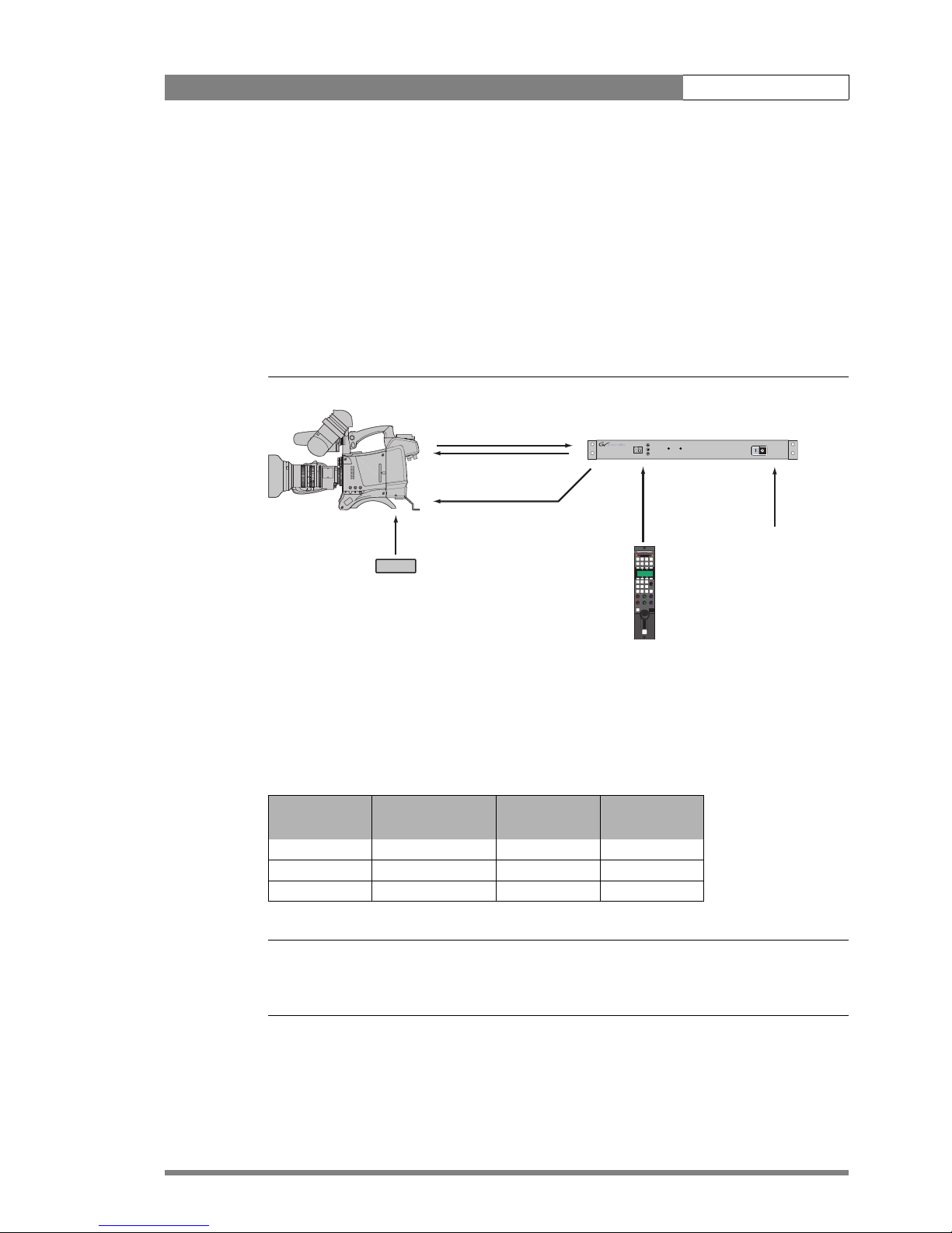
1.4.1 Digilink system SDI coax configuration
A camera head with an LDK 5481 adapter can be connected to the LDK 4700/00 base unit
using two coax SDI cables. The maximum length of cable that can be used is 250m (820 ft).
High quality coax cable should be used (for example, Belden 1694A). The DC power supply
for the camera is supplied directly to the adapter by an optional local power supply or by the
base unit (using a DC power cable).
Figure 1-1. DigiLink system SDI coax connection
When a DC power cable is used to power the camera from the base unit, refer to section 6 for
the pin layout of the DC connectors. The maximum length of the cable depends on the type of
cable and the power used by the camera. The table below is an indication of the cable lengths
that can be used.
Table 1-2. cable length indication for DC power cable
☞
Note
Always use a power cable from the portable power cables category, type W, G, G-GC or PPE.
The cable should be listed in accordance with NEC article 400 of ANSI/NFPA70.
cable type cross section
max. length
(3A/40W)
max. length
(5A/60W)
AWG 20 0.75 mm
2
50 m 30 m
AWG 18 1.0 mm
2
75 m 45 m
AWG 16 1.3 mm
2
125 m 75 m
SD Camera head
LDK 5481
DigiLink Adapter
Ready On-air
Clear
ND1/4
ND1/16
ND1/64
Clear
Star 4P
Star 6P
Soft Focus
Smart
card
Pow
er
on
P
w
e
l
1
2
3
4
A
B
C
D
2x coax cable
max. length 250m. (820ft.)
optional DC power cable
LDK 4700/10 DigiLink Base Unit
OCP 400/10
RS-422 with
powerline LDK8121/xx
max. length 25m. (82ft.)
mains power
optional LDK 5901
DC power supply
v4.0
LDK 5481 + LDK 4700 User’s Guide | DigiLink system 1-4
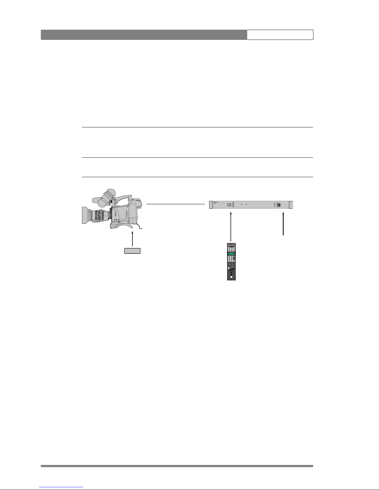
1.4.2 DigiLink system multicore configuration
A camera head with an LDK 5481 adapter can be connected to the LDK 4700/10 base unit
using multicore cable. The maximum length of cable that can be used is 75m (250 ft). The
base unit can supply power for the camera via the multicore cable. The power consumption
of the camera may reduce the maximum length of cable that can be used, so alternatively, the
power for the camera can be supplied directly to the adapter from the optional LDK 5901
power supply.
☞
Note
Always use a listed 26-pin CCZ-A multicore cable compliant with EBU N21 (for example, Draka
multicore camera cable type 755-2 PVC.)
Figure 1-3. DigiLink system multicore connection
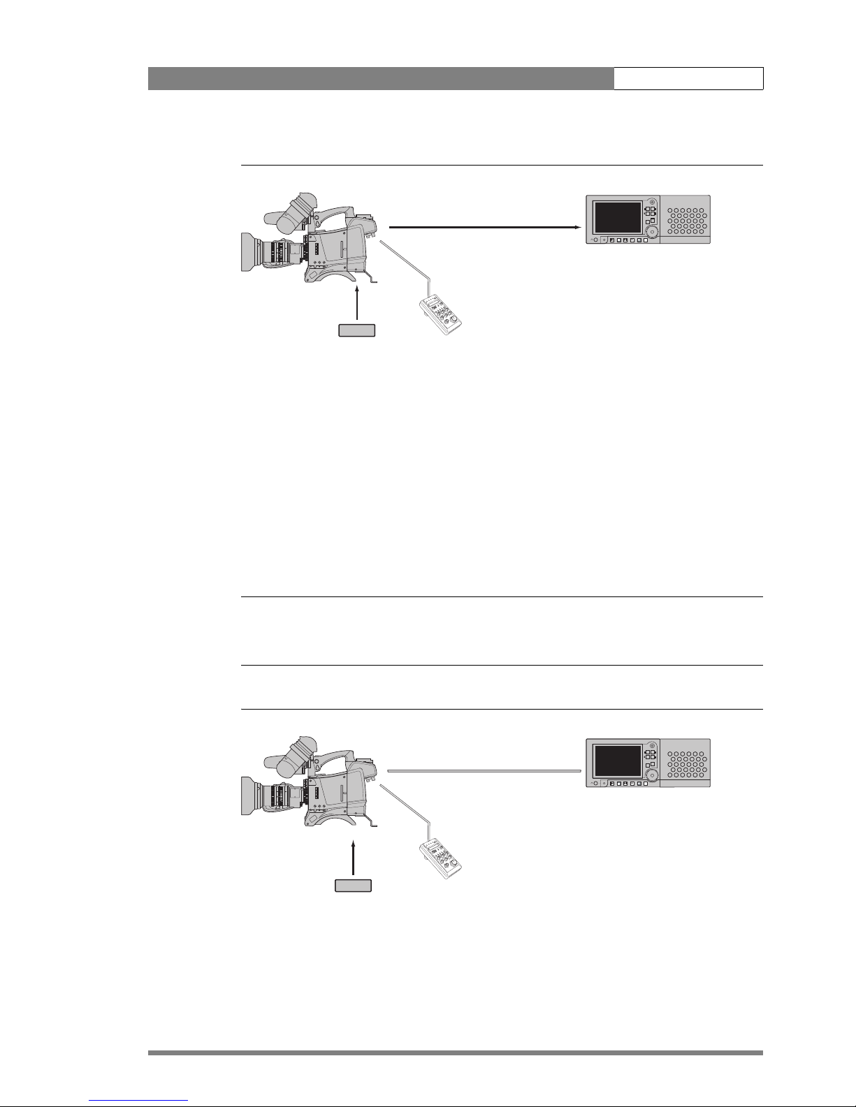
1.4.3 Stand alone SDI coax configuration
A camera head with an LDK 5481 adapter can be connected to a recorder unit using an SDI
coax cable. Only the SDI signal is passed via the coax cable. The maximum length of cable that
can be used is 300m (1000 ft). High quality coax cable should be used (for example, Belden
1694A). The DC power supply for the camera is supplied directly to the adapter. The LCP 100
can be connected directly to the camera.
26-pin CCZ-A Multicore cable
max. length 75m (250ft.)
SD Camera head
LDK 5481
DigiLink Adapter
Ready On-air
Clear
ND1/4
ND1/16
ND1/64
Clear
Star 4P
Star 6P
Soft Focus
Smart
card
Power
on
P
w
e
l
1
2
3
4
A
B
C
D
LDK 4700/10 DigiLink Base Unit
OCP 400/10
RS-422 with
powerline LDK8121/xx
max. length 25m. (82ft.)
mains power
optional LDK 5901
DC power supply
v4.0
LDK 5481 + LDK 4700 User’s Guide | DigiLink system 1-5
Figure 1-4. Stand alone SDI coax configuration
1.4.4 Stand alone multicore configuration
A camera head with an LDK 5481 adapter can be connected to a recorder using a multicore
cable. Power can be supplied by the recorder via the multicore cable or directly to the adapter
itself. To avoid degradation in the video signal, the maximum cable length is restricted to 5m
(17 ft.) when the component outputs are used in the recorder. The LCP 100 can be connected
directly to the camera.
If the recorder uses the SDI signals, then the maximum length of cable depends on the ability
of the recorder unit to supply sufficient power to the camera. When the adapter is powered
directly the maximum length is 100m (330ft). With minimum power supplied from the recorder
unit the maximum length is 25m (80ft).
☞
Note
Always use a listed 26-pin CCZ-A multicore cable compliant with EBU N21 (for example, Draka
multicore camera cable type 755-2 PVC)
Figure 1-5. Stand alone multicore configuration
SDI coax cable
SD Camera head
LDK 5481
DigiLink Adapter
Clear
ND1/4
ND1/16
ND1/64
Clear
Star 4P
Star 6P
Soft Focus
Smart
card
Power
on
P
w
e
l
1
2
3
4
A
B
C
D
Video recorder
LCP 100
L
CP
100
l
o
c
a
l
c
o
n
tr
o
l
p
a
n
e
l
V
TR o
n/o
ff
O
p
e
rat
e
VTR start
/
sto
p
G
a
i
n
B
l
a
c
k
Fu
nc
t
io
n
!
Batt
T
ap
e
nd/
re
optional LDK 5901
DC power supply
26-pin CCZ-A Multicore cable
SD Camera head
LDK 5481
DigiLink Adapter
Clear
ND1/4
ND1/16
ND1/64
Clear
Star 4P
Star 6P
Soft Focus
Smart
card
Pow
er
on
P
w
e
l
1
2
3
4
A
B
C
D
Video recorder
LCP 100
LCP
100
l
o
c
a
l
c
o
n
t
r
o
l
p
a
n
e
l
VTR on/off
O
pe
rate
VTR start/stop
G
a
i
n
B
l
a
c
k
Fu
n
ctio
n
!
Batt
Tap
e
nd/re
optional LDK 5901
DC power supply
v4.0
LDK 5481 + LDK 4700 User’s Guide | DigiLink system 1-6
1.5 Int e rcom
An intercom channel connects the base unit to the camera operator's headset. The operator's
intercom microphone signal is sent to the base unit. The headset can be connected to the 5
pin XLR headset connector at the back of the DigiLink adapter. For the connector and detailed
pin descriptions refer to chapter 2.7.6.
A conversation is started when the camera operator presses the VTR Start button at the
front of the camera or the VTR button on the lens. The function and behaviour of this
button can be defined in the
INSTALL menu of the camera. Refer to the camera’s user’s
guide.
The volume of the headset earmuffs can be adjusted by turning the audio volume knob at the
front (right side) of the camera.
Intercom configuration
The sidetone volume level (feedback signal from the microphone to the earmuffs) can be
adjusted withthe
INSTALL/INTERCOM/SIDETONE function n the camera (available only
when a 4-wire connection is used).
Depending on the type of microphone the following items can be set in the
INSTALL/
INTERCOM
menu in the camera:
• Microphone gain level (0 or +40 dB) with the CAM.MIC_GAIN function;
• Microphone power can be switched on or off with the CAM.MIC_POWER function.
Both 2-wire and 4-wire intercom connections can be used. On the base unit, set the setup
switch S1 in the Off-position when a 4-wire connection is used and set it in the On-position
when a 2-wire connection is used. Refer to chapter 3.6.1 for the description of the setup
switch.
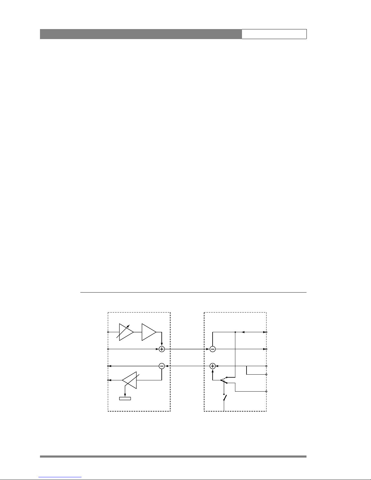
The following figure gives an overview of the routing of the intercom. For the connector and
detailed pin descriptions refer to chapter 3.5.
Figure 1-6. Schematic overview of the intercom routing
DigiLink adapter DigiLink base unit
Cam SDI OUT
PROD out (4-wire)
PROD in/out (2-wire)
0 dBu
pin 1,9 return
PROD in (4-wire)
0 dBu
pin 5, 13 return
SDI
EXT
TP
Cam Video
0 / 40 dB
front volume
Cam SDI IN
S1 Off = 4-wire
S1 On = 2-wire
2 w.
4 w.
EXT/TP video
Out
0 dBu
Mic in
-24/-64 dBu

v4.0
LDK 5481 + LDK 4700 User’s Guide | DigiLink system 1-7

v4.0
LDK 5481 + LDK 4700 User’s Guide | DigiLink system 1-8

v4.0
LDK 5481 + LDK 4700 User’s Guide | LDK 5481 DigiLink Adapter 2-1
Chapter 2
LDK 5481 DigiLink Adapter
Important information (English)
Read this information carefully before installing or servicing this equipment and retain them for
future reference. Read and comply with the warning and caution notices that appear in the
manual.
Any changes or modifications not expressly approved in this manual could void your authority
to operate this equipment.
Safety Summary
This informaton is intended as a guide for trained and qualified personnel who are aware of
the dangers involved in handling potentially hazardous electrical/electronic equipment. It is
not intended to contain a complete list of all safety precautions which should be observed by
personnel in using this or other electronic equipment.
The installation of this equipment involves risks both to personnel and equipment and must
be performed only by qualified personnel exercising due care.
During installation and operation of this equipment, local building safety and fire protection
standards must be observed.
Whenever it is likely that safe operation is impaired, the apparatus must be made inoperative
and secured against any unintended operation. The appropriate servicing authority must then
be informed. For example, safety is likely to be impaired if the apparatus fails to perform the
intended function or shows visible damage.
Warnings
Warnings indicate danger that requires correct procedures or practices to prevent death or
injury to personnel.
• Do not modify this equipment.
• Installation of this equipment must only be performed by qualified personnel.
• Do not use any accessories other than those recommended by the manufacturer.
• In case of an emergency ensure that the power is disconnected.

v4.0
LDK 5481 + LDK 4700 User’s Guide | LDK 5481 DigiLink Adapter 2-2
• There are no user servicable parts inside. Refer servicing to qualified personnel only or
contact your local Grass Valley representative.
Cautions
Cautions indicate procedures or practices that should be followed to prevent damage or
destruction to equipment or property.
• Always switch off the camera before changing the power supply.
• Be extremely careful with the connectors between the camera head and the adapter. Do
not allow the guide pins to damage the pins of the connector. Follow these steps in the
order given. Tightening the screws in the wrong order could result in mechanical damage
to the camera. Loosening the screws in the wrong order could result in mechanical
damage to the camera.
• To prevent risk of overheating, ventilate the units correctly.
• Do not subject the unit to severe shocks or vibration.
• Do not expose the unit to extremes of temperature.
• Do not leave the unit in direct sunlight or close to heating appliances for extended periods.
• Avoid very damp places. If the environment is wet or damp a rain cover must be used to
protect the unit.
Wichtige Hinweise (Deutsch)
Lesen Sie bitte diese Hinweise genau bevor Sie diese Apparatur installieren und erhalten Sie
Sie für künftiges Nachslagen. Beachten und Lesen Sie alle mit “Achtung” und “Vorsicht”
gekennzeichneten Warnhinweise.
Änderungen haben zur Folge, dass die Garantie ungültig wird und der Benutzer für etwaige
durch die veränderte Ausrüstung verursachte Störungen haftbar gemacht werden könnte.
Sicherheit (Zusammenfassung)
Diese Informationen sind als Leitfaden für qualifiziertes Fachpersonal gedacht, das die
Gefahren beim Umgang mit potenziell gefährlicher elektrischer/elektronischer Ausrüstung
kennt. Es handelt sich dabei nicht um eine vollständige Zusammenstellung aller
Sicherheitsvorkehrungen, die beim Gebrauch dieser oder anderer elektronischer Geräte zu
beachten sind.
Die Montage, Wartung und Instandsetzung dieser Ausrüstung ist mit Risiken für Personal und
Ausrüstung verbunden und darf nur von qualifiziertem Personal vorgenommen werden, wobei
mit der nötigen Sorgfalt vorzugehen ist.
Mit der Montage, Bedienung, Instandhaltung oder Instandsetzung dieser Ausrüstung
betrauten Personen wird dringend geraten, sich mit der Theorie und Praxis der Ersten Hilfe
vertraut zu machen.
Beim Einbau und Betrieb dieser Ausrüstung müssen die örtlichen Gebäudesicherheits- und
Brandschutzvorschriften beachtet werden. Vor dem Anschluss der Ausrüstung an die
Stromversorgung der Anlage muss überprüft werden, ob der Schutzleiter intakt ist.
 Loading...