


THOMSON LDK 20 S Operator's Manual

LDK 20(S)LDK 20(S)
LDK 20(S)LDK 20(S)
LDK 20(S)
Studio Camera
Operator’s Manual
3922 496 48631 St.37

Für diese Unterlage behalten wir uns
alle Rechte vor (Gemäß DIN 34).
Technische Änderungen im Zuge der
Weiterentwicklung vorbehalten.
Copyright
FCC Class A Statement
Declaration of Conformity
Copying of this document and giving
it to others, and the use or communication of the contents thereof,
are forbidden without express authority. Offenders are liable to the
payment of damages. All rights are
reserved in the event of the grant of
a patent or the registration of a utility
model or design. Liable to technical
alterations in the course of further
development.
Toute communication ou reproduction de ce document, toute exploitation ou communication de son
contenu sont interdites, sauf autorisation expresse. Tout manquement à cette règle est illicite et
expose son auteur au versement de
dommages et intérêts. Tous nos
droits sont réservés pour le cas de la
délivrance d'un modèle d'utilité. Sous
réserve de modification au cours de
l'évolution technique.
© Thomson Multimedia Broadcast Solutions 2002
We, Thomson Broadcast Solutions Nederland B.V., Kapittelweg 10, 4827 HG Breda, The Netherlands declare under
our sole responsibility that this product is in compliance with the following standards:
EN60065
EN55103-1
EN55103-2
following the provisions of:
a. the Safety Directives 73/23//EEC and 93/68/EEC
b. the EMC Directives 89/336/EEC and 93/68/EEC
: Safety
: EMC (Emission)
: EMC (Immunity)
This product generates, uses, and can radiate radio frequency energy and if not installed and used in accordance with
the instructions, may cause interference to radio communications.
It has been tested and found to comply with the limits for a class A computing device pursuant to Subpart J of part 15
of FCC rules, which are designed to provide reasonable protection against such interference when operated in a commercial environment.
Operation of this product in a residential area is likely to cause interference in which case the user at his own expense
will be required to take whatever measures may be required to correct the interference.

02.40.2 Operator's Manual LDK 20(S) - Studio Camera I
LDK 20(S)
Studio Camera
Operator's Manual
Contents
About this Manual .................................................II
Introduction ...................................................... 1-1
General .............................................................. 1-2
Features ............................................................ 1-3
Aspect ratio ....................................................... 1-3
Important Precautions ........................................ 1-4
Assembling the Units ...................................... 2-1
Transport Case .................................................. 2-2
Rain and Off-use Cover ...................................... 2-3
Lens ................................................................... 2-4
Viewfinder .......................................................... 2-5
Camera Balance ................................................ 2-6
Scriptboard ........................................................ 2-7
Configurations ................................................. 3-1
Basic Configurations .......................................... 3-2
Two-wire Data Control Bus ................................. 3-5
Other Control Features ....................................... 3-5
Video Routing .................................................... 3-6
Audio/Intercom Routing ...................................... 3-7
Location of Controls and Functions ............... 4-1
Power Supply ..................................................... 4-2
Video Functions ................................................. 4-3
Monitoring Functions .......................................... 4-5
Viewfinder LED's ................................................ 4-7
Viewfinder Controls ............................................ 4-8
Control Functions ............................................... 4-9
Audio / Intercom .............................................. 4-10
Auxiliary Functions .......................................... 4-12
Auxiliary Functions .......................................... 4-13
Shooting ........................................................... 5-1
Using the Camera .............................................. 5-2
Standard settings ............................................... 5-3
Colour Bar .......................................................... 5-3
Gain selection .................................................... 5-4
Optical filter selection ........................................ 5-4
Colour temperature selection .............................. 5-5
Auto-White Balance ........................................... 5-5
Operating the Menu System ............................ 6-1
Introduction ........................................................ 6-2
Finding your way ................................................ 6-2
Making Changes ................................................ 6-3
Alternative Ways to Navigate ............................. 6-4
Menu Structure .................................................. 6-5
Menu Install Features ........................................ 6-6
Appendix ......................................................... A-1
Menu Structure ................................................. A-3
List of Menu Functions...................................... A-8

II Operator's Manual LDK 20(S) - Studio Camera 02.40.2
About this Manual
This user guide is part of a complete documentation
set for the camera which also includes an Installation
& 1st Line Service Manual, and a 2nd Line Service
Manual.
Purpose of this manual
The purpose of this manual is to present a detailed
description of how to operate the LDK 20(S) Studio
Camera. It provides the information necessary to use
the camera in different configurations and with various
attachments. With this manual it is possible to discover
all the operating features of the camera and so use it
to its full potential. The manual should be used
together with the camera to explore and learn about the
many sophisticated control functions available.
Intended audience
This user's guide can be used by inexperienced
camera operators who are new to Thomson Multimedia
Broadcast Solutions cameras as well as those who
have previous experience of operating cameras. The
guide is so designed that it can be used as an
introduction to those who are new to the camera, as a
simple procedural guide to those who wish to set-up
and start shooting immediately, and as a reference
work to be consulted as required during the long life of
the camera.
Structure of this manual
The manual is divided into six sections and an appendix:
Section 1: Introduction
This section outlines the technology used in the
LDK 20(S) camera and how this translates into a
practical, useable camera. It lists the main features of
the camera and also the precautions that must be
taken into account when using it.
Section 2: Assembling the Units
Section 2 provides information on the physical
assembly of the camera and on how accessories can
be used to expand the possibilities of the camera. The
mounting of accessories and packing for transport is
also explained.
Section 3: Configurations
The LDK 20(S) is a multi-functional camera and this
section describes the various ways that it can be used;
on its own or in a studio system with other cameras.
Information on the cables, control panels and the
control bus is also provided as is information on the
main video and audio signal paths through the system.
Section 4: Location of Controls and Functions
This section shows the physical location of the controls
and connectors on the camera. These are grouped
according to their function so as to provide a quick
reference guide to the operation of a particular aspect
of the camera.
Section 5: Shooting
This section contains information on the practical use
of the camera using the viewfinder display and the
switches to control the camera.
Section 6: Operating the Menu System
Because the LDK 20(S) offers such a wide range of
functions, this section describes the structure of the
control system. It contains procedures for controlling
the menu system and explains how to program the
menu system for your personal preferences. The
menu structure and the methods of function selection
are also explained.
Appendix
The appendix contains a list of the functions available
on the camera.

Introduction Operator's Manual LDK 20(S) - Studio Camera 1-1
Section 1
Introduction
This section outlines the technology used in the LDK 20 camera and how this translates into a
practical, useable camera. It lists the main features of the camera and also the precautions that must
be taken into account when using it.
Contents
General .............................................................. 1-2
Features ............................................................ 1-3
Aspect ratio ....................................................... 1-3
Important Precautions ........................................ 1-4

1-2 Operator's Manual LDK 20(S) - Studio Camera Introduction
The digital contour processing uses full amplitude
600% video RGB signals via an extended dynamic
range contour circuit. It enables the optimum levels of
contour control at highlights (in knee) and at sharp
edges, without first having to compress the highlight
signal. The dual auto skin tone contour circuitry
handles 360° of the colour vector.
Colorimetry is selected by means of a variable 6-point
digital matrix or via preset matrices (1:1, EBU, RAI,
BBC and Skin).
Digital gamma circuits as well as providing a wide
range of standardised gamma curves also enable soft
contrast in black scenes to be enhanced, together
with hard contrast and saturated colour in bright
scenes.
Digital contrast circuitry provides a black stretch
function for more detail in black areas and a black
press function for improving the contrast impression
by simulating the S-curve of film.
The LDK 20(S) camera uses Dynamic Pixel
Management (DPM). This new technology enables
the format of the sensors to be switched between 4:3
and 16:9 aspect ratios at the touch of a switch without
loss of horizontal resolution. The 1000 pixels per line
in both formats ensures that there is no loss in
horizontal viewing angle.
Another aspect of the 2/3" DPM sensors is that there
is no loss of vertical resolution between formats. They
have a highlight compression/dynamic range of 600%
and a high linear sensitivity over all camera lens
apertures. The frame transfer technology ensures
that there is no lag nor smear. The 2/3-inch DPM
sensor has been designed so that vertical pixels are
addressable in groups of 3 or 4, for operating in 16:9
and 4:3 aspect ratios respectively. Switching from the
basic 4:3 sensor format to 16:9 gives no loss of
horizontal or vertical resolution. In fact, 1000 pixels
per line with both aspect ratios ensures high resolution
in the red, green and blue camera channels.
General
LDK 20(S)
The
HiRes
Digital LDK 20(S) is a Studio camera
which uses 2/3" frame transfer sensors. The advanced
HiRes
Digital processing of the camera is based on
12-bit A/D converters, 14-bit DSP circuits and more
than 20-bit internal processing. Two DSPs combine
all major camera functions in the digital domain,
including knee, gamma, contour, matrix and colour
correction. A software programmable video path
enables the sequence of the matrix and gamma
function to be selected for precise colour matching of
different cameras.
The Intelligent Continuous Automatics facility provides
automatic control of black levels and black shading.
Each sensor has two lines of elements that are
protected from incoming light and therefore give a
true indication of black. The black reference signal
that they provide is used in the camera pre-processor
circuits to monitor temperature changes which, if not
corrected, would alter the black level. In this way
continuous automatic correction is applied without
operator intervention.
To emulate the softly limiting S-shaped transfer
characteristics of film, the TV camera's near linear
characteristics are compressed above a certain point,
the knee. The pivoting knee circuit of the LDK 20(S)
camera adapts both the knee point and the
compression ratio according to the highlight content
of the picture. Significant highlights lower the knee
point to give more room for compression, while minor
highlights only affect the upper part of the transfer
characteristic. Signals below the knee point remain
unaffected. As a result, compression is only applied
where necessary and in proportion to the highlight,
and the pictures obtained have true film-like quality.
The 12-bit A/D processing of a 600% video level
assures high levels of accuracy for this advanced
dynamic handling.
Digital True Colour Knee circuitry maintains the correct
hue for 600% compressed video highlights. With this
system colours are faithfully reproduced, even
overexposed skin tones.

Introduction Operator's Manual LDK 20(S) - Studio Camera 1-3
Features
LDK 20(S)
• 3 x 2/3-inch Thomson Frame Transfer CCD sensors
ensure no vertical smear.
• 12-bit
HiRes
Digital processing with unique software
programmable video path.
• Superior all digital highlight handling with a dynamic
range of up to 600%.
• Unique circuitry for pivoting knee and True Colour
Knee.
• Wide range of presets and variable 6-point digital
matrix assure accurate colour matching.
• Digital gamma with unique standard preset values
and highest accuracy.
• Digital contour with an extensive range of
parameters.
• Advanced contour correction includes two automatic
skin settings.
• Intelligent Continuous Automatics black levels, black
shading and video levels - no set-up time required.
• Digital contrast with standard black stretch and
black press.
• International standard 2/3-inch lens interface.
• 6-position standard filter wheel cassette,
exchangeable.
• Extensive two-wire or four-wire intercom to
international standards including RTS.
Aspect ratio
The two aspect ratios that can be selected are the
conventional 4:3 and the widescreen 16:9. Because
of the dynamic pixel management (DPM) used in the
LDK 20(S) camera, there is no loss of either vertical
or horizontal resolution between these two modes.
Letterbox mode
When the conventional 4:3 mode is selected, there is
the additional choice of a letterbox format providing a
16:9, 16:10, or 16:11 blanked display. In the letterbox
format the number of vertical lines is reduced because
of the blanking. The signal, however, is fully compatible
with the conventional 4:3 standard. The use of the
letterbox mode therefore, is dictated by the requirement
of providing a widescreen shot while remaining
compatible with the present 4:3 standard.
True widescreen mode
The widescreen 16:9 aspect ratio is selected when
there is a need for shots that can take full advantage
of the picture performance of EDTV (extended
definition TV) systems such as PALplus.
• Protected, easy-to-operate controls and switches
with read-out of all settings.
• 7-inch viewfinder status read-out of primary camera
functions
• Clean scan feature allows capture of computer and
other monitor pictures.
• Series 9000 Universal Camera Control System
from the Base Station.
• Optional 4:2:2 serial digital outputs from the Base
Station.
• Triax system allows for cable lengths up to 2,400
meters (7,875 feet).
• Digital Modem channel data transmission over triax
system for robotics and other applications
• DPM Frame Transfer sensors with 1000 horizontal
pixels in 4:3 and 16:9 aspect ratios, and the same
number of vertical lines in both formats.
• No change in horizontal viewing angle - so no wide
angle convertors required.
• Simple no-compromise switching between 4:3 and
16:9 - futureproof concept with no later upgrades
needed for either camera or lenses.
• Automatic selection of correct viewfinder mode for
4:3 and 16:9.
1-4 Operator's Manual LDK 20(S) - Studio Camera Introduction
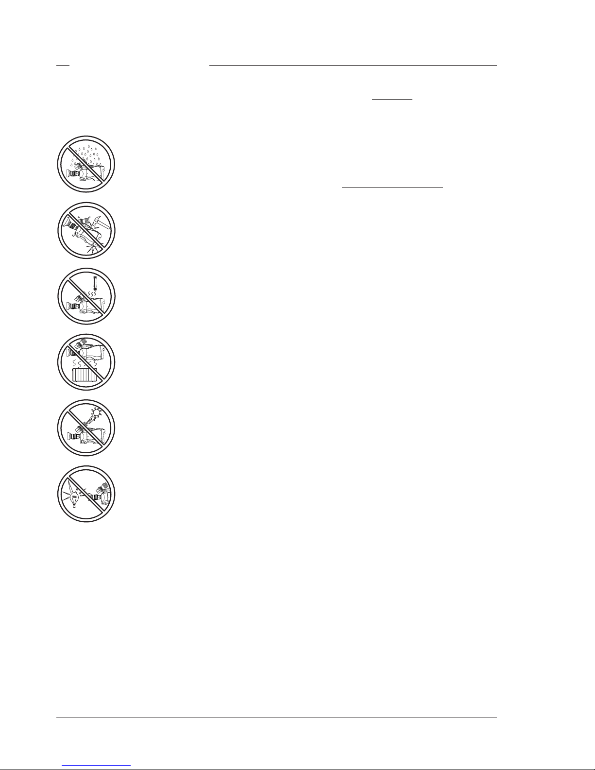
Important Precautions
To ensure continual high performance from the
LDK 20(S) camera take the following precautions into
consideration:
Avoid very damp places. If the
environment is wet or damp a
raincover must be used to protect it.
Do not subject the unit to severe
shocks or vibration.
Do not expose the camera to
extremes of temperature.
Do not leave the unit in direct sunlight
or close to heating appliances for
extended periods.
Do not allow sunlight to shine into the
viewfinder.
Avoid extreme highlights as these
can cause various kinds of optical
reflections.
Warnings
If the LDK 20(S) is in a wet or damp environment, a
raincover must be used to protect it for personal
safety reasons (EN60065). The raincover LDK6988/
00 protects the camera according to safety specification EN60529 up to level IPX2 (spraying water).
FCC Class A Statement
This equipment generates, uses, and can radiate
radio frequency energy and if not installed and used
in accordance with the instructions, may cause
interference to radio communications.
It has been tested and found to comply with the limits
for a class A computing device pursuant to Subpart J
of part 15 of FCC rules, which are designed to provide
reasonable protection against such interference when
operated in a commercial environment.
Operation of this equipment in a residential area is
likely to cause interference in which case the user at
his own expense will be required to take whatever
measures may be required to correct the interference.

Assembling the Units Operator's Manual LDK 20(S) - Studio Camera 2-1
Section 2 provides information on the physical assembly of the camera and on how accessories can
be used to expand the possibilities of the camera. The mounting of accessories and packing for
transport is also explained.
Section 2
Assembling the Units
Contents
Transport Case .................................................. 2-2
Rain and Off-use Cover ...................................... 2-3
Lens ................................................................... 2-4
Viewfinder .......................................................... 2-5
Camera Balance ................................................ 2-6
Scriptboard ........................................................ 2-7
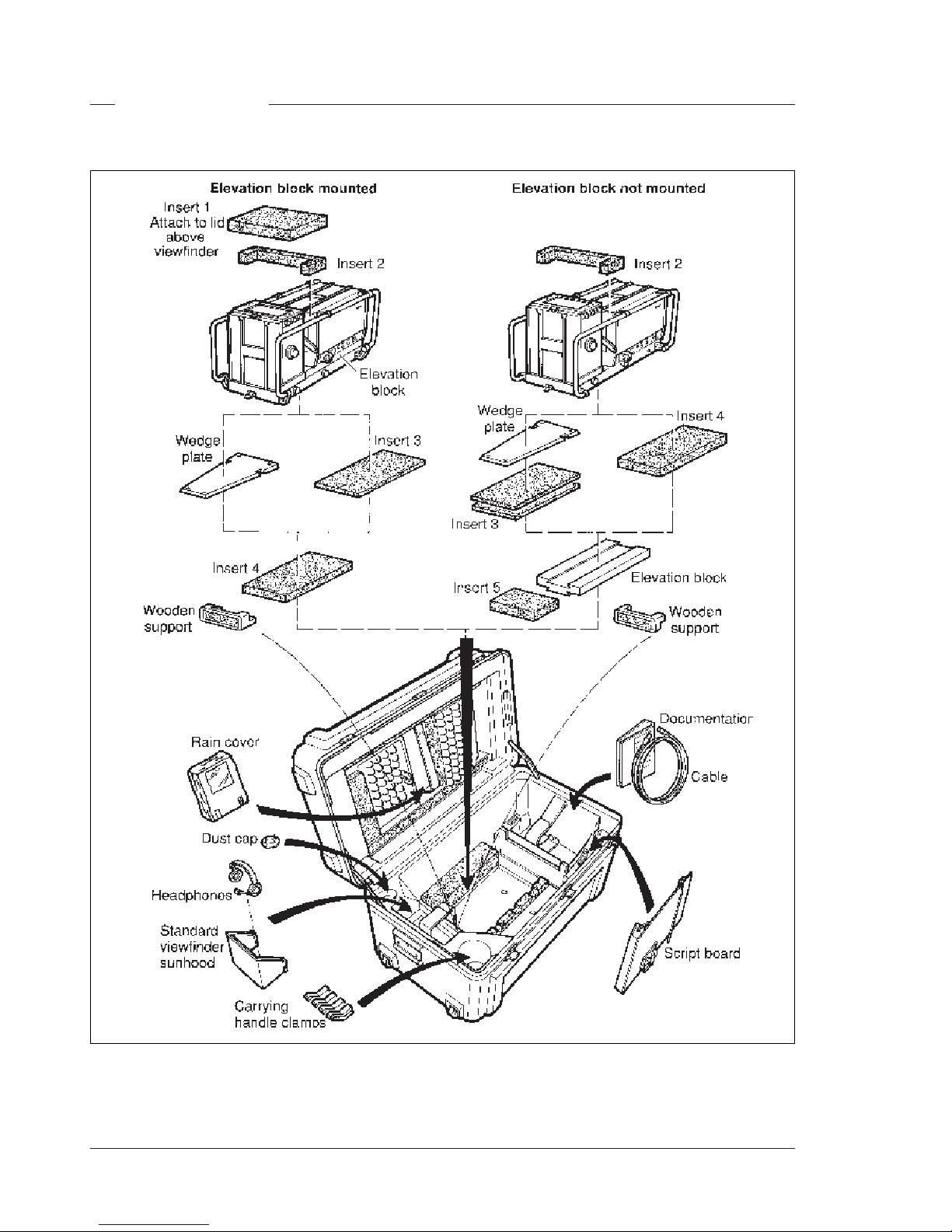
2-2 Operator's Manual LDK 20(S) - Studio Camera Assembling the Units
It is important to protect your camera against damage
when transporting it. To do this, a transport case is
available for the camera, lens, viewfinder and some
accessories.
The camera is packed in the transport case as shown
in the figure above. This ensures that the camera is not
damaged during transport. Do not forget to secure the
straps around the items to keep them in place.
Transport Case
Assembling the Units Operator's Manual LDK 20(S) - Studio Camera 2-3
Rain and Off-use Cover
The rain and off-use cover LDK 6988/00 must be used
when the camera system is in a wet or damp
environment. This protection is necessary for personal
safety reasons.
The cover can also be used indoors to protect the
camera when it is used in dusty environments. It can
also be useful if the camera is being put into storage.
For more information on how to put on the cover refer
to the User's Guide which is supplied with it.
CAUTION
Do not use the camera outdoors
without a rain cover
Camera Lock Screws
HiRes
Digital
2-4 Operator's Manual LDK 20(S) - Studio Camera Assembling the Units
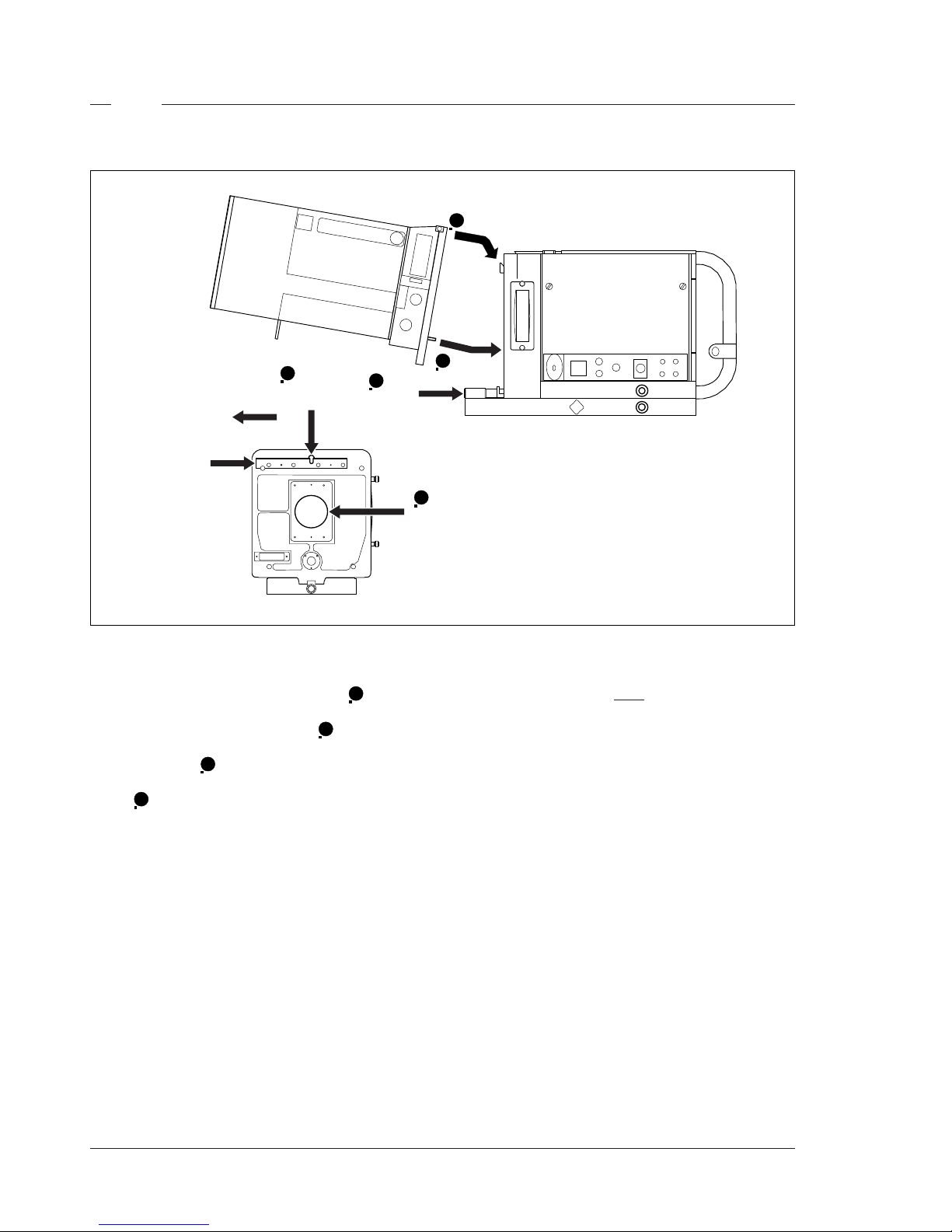
To mount a standard size lens to the camera head
proceed as follows:
a. Ensure that the lens locking handle 1 is in the
unlocked position.
b. Remove the dust protection cap 2.
c. Hook the lens onto the support rail ensuring that the
upper lens pin 3 fits into the slot in the support rail.
d. Swing the lens downwards so that the lower lens
pin 4 fits into the hole in the front of the camera.
e. Turn the lens locking handle clockwise to secure
the lens in place.
To remove the lens follow this procedure in reverse.
Note
Always mount the dust protection cap when the
lens is not connected to the camera.
Lens
HiRes
Digital
Support
Rail
3
Support
Rail
Slot
1
Lens
Locking
Handle
2
Dust
protection
cap
3
4
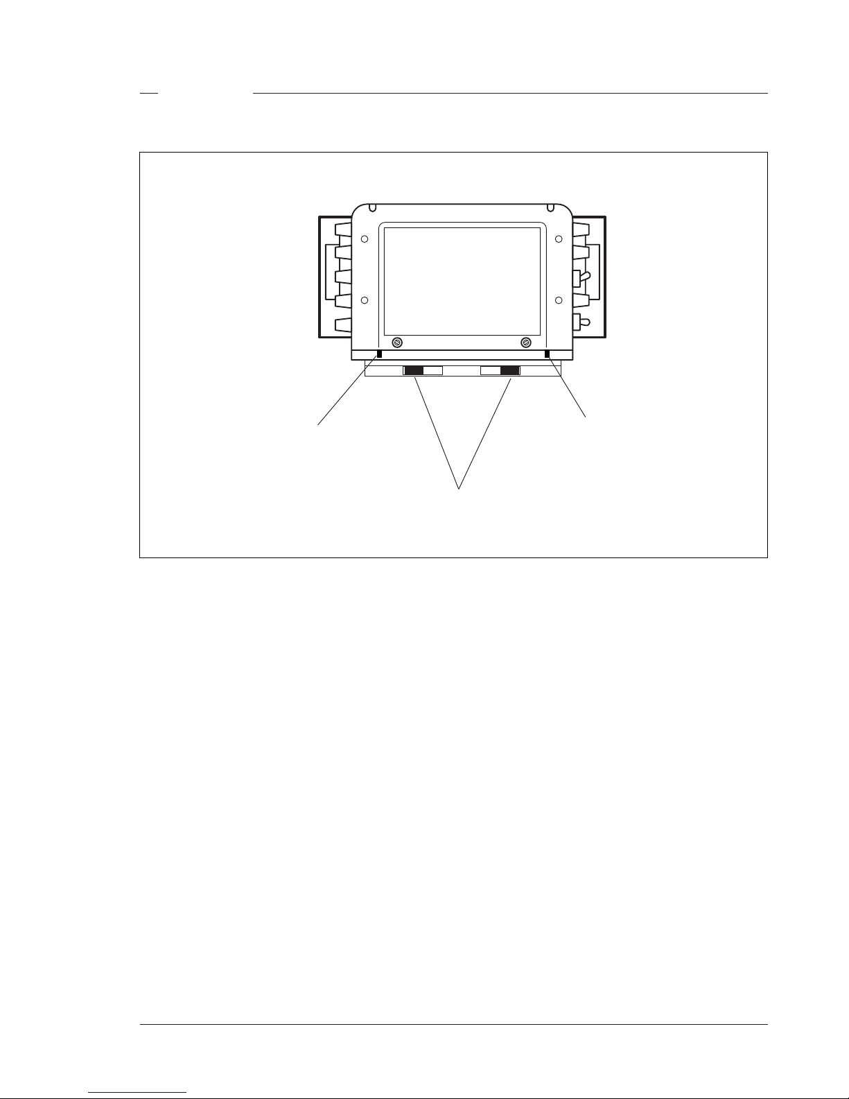
Assembling the Units Operator's Manual LDK 20(S) - Studio Camera 2-5
The viewfinder is normally delivered separately. To
mount the viewfinder on to the top of the camera
proceed as follows:
a. Slide the viewfinder along the rails on top of the
camera until it can go no further.
b. Push both locking levers inwards and slide the
viewfinder until it firmly engages the connector.
c. Release the locking levers and ensure they click
into the lock position.
Viewfinder
To attach the viewfinder hood to the viewfinder proceed
as follows:
a. Clip the hood onto the slots on top of the viewfinder.
b. Swing it down and attach it to the front of the
viewfinder by pushing the two hood locking knobs
outwards.
c. Let go of the hood locking knobs and ensure that
the hood clips into place.
Viewfinder
Hood
Locking
Knob
Viewfinder
Hood
Locking
Knob
Viewfinder Locking Levers
2-6 Operator's Manual LDK 20(S) - Studio Camera Assembling the Units
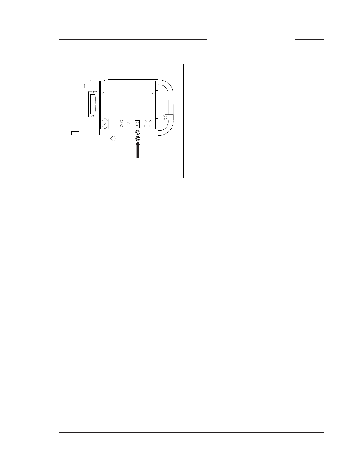
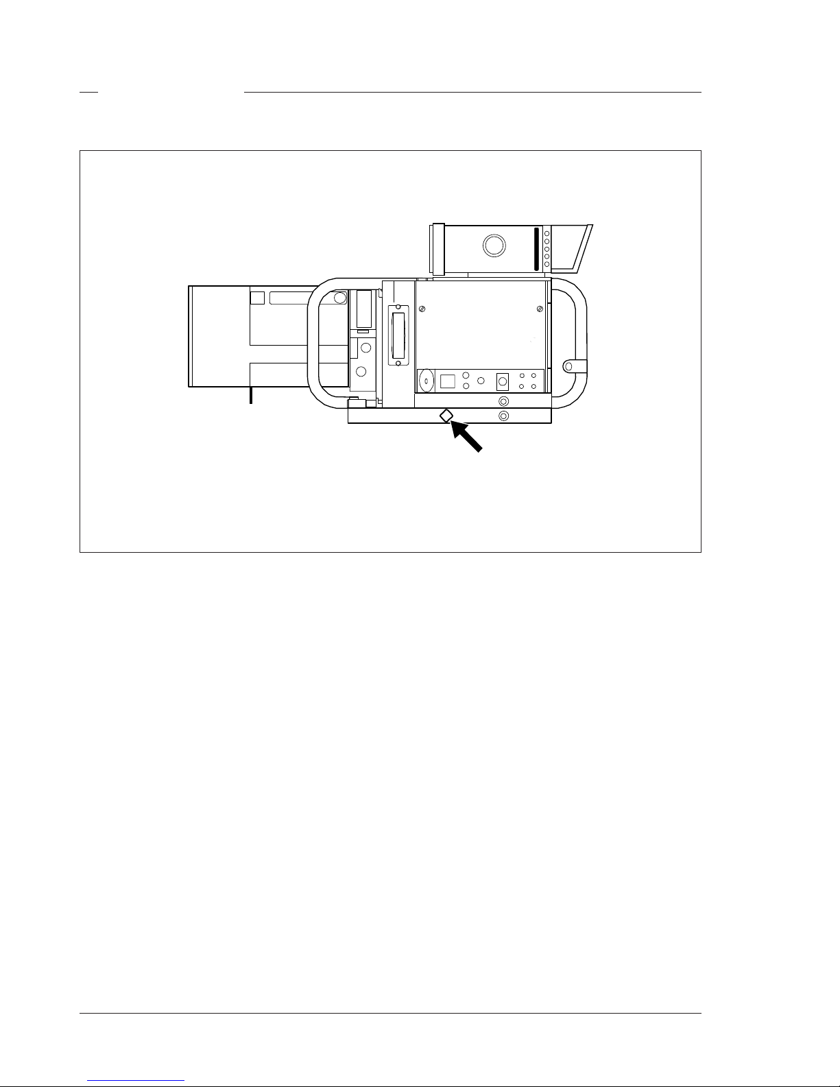
Camera Balance
When the lens is mounted on the camera it may be
necessary to balance the camera on the tripod. Proceed
as follows:
a. Loosen the balance lock knob on the side of the
footbed by turning it counterclockwise.
b. Move the footbed back and forth along the tripod
until the best balance is achieved.
c. Tighten the balance lock knob on the side of the
footbed by turning it clockwise.
HiRes
Digital
Camera Balance Lock Knob
Assembling the Units Operator's Manual LDK 20(S) - Studio Camera 2-7
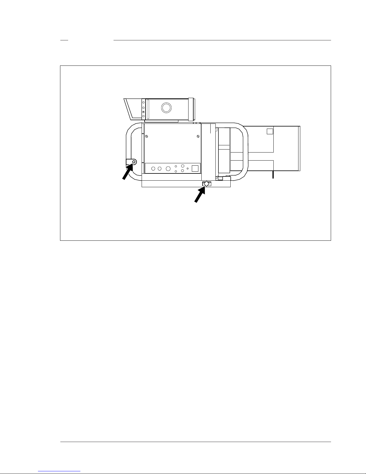
Scriptboard
To attach the script board to the carrying bars of the
camera proceed as follows:
a. Turn the tightening lever on the script board fully
counterclockwise so as to reduce the diameter of
the spindle.
b. Insert the spindle into the attachment on the
carrying bars.
c. Tighten the lever.
d. Connect Scriptboard light cable to one of the two
the scriptlight connectors at the rear of the camera.
HiRes
Digital
Triax Cable Clamp
Script Board
Mounting
Attachment

2-8 Operator's Manual LDK 20(S) - Studio Camera Assembling the Units

Configurations Operator's Manual LDK 20(S) - Studio Camera 3-1
The LDK 20(S) is a multi-functional studio camera and this section describes the various ways that
it can be used; on its own or with other cameras. Information on the cables, control panels and the
control bus is also provided as is information on the main video and audio/intercom signal paths
through the system.
Section 3
Configurations
Video Routing .................................................... 3-6
Audio/Intercom Routing ...................................... 3-7
Contents
Basic Configurations .......................................... 3-2
Two-wire Data Control Bus ................................. 3-5
Other Control Features ....................................... 3-5

3-2 Operator's Manual LDK 20(S) - Studio Camera) Configurations
Basic Configurations
Stand-alone mode
The LDK 20(S) is a studio camera that can be used in
various configurations. The first configuration is the
stand-alone mode where the camera is connected to
a separate VTR. The LDK 20(S) camera is delivered
ready to operate in the remote mode. If the camera
has been switched to the local (stand-alone) mode,
follow the instructions to switch it back to the remote
mode in Section 2 of the installation manual. The
power supply is now provided to the camera via the
mains AC power supply at the right side of the
camera. The VTR is connected to the 26-pole
connector on the rear of the camera by means of the
optional VTR cable LDL 2110. The camera connector
provides SMPTE/EBU video component signals for
the VTR. The playback signal from the VTR can be
monitored in the viewfinder. The camera controls are
all operated locally on the camera or via a single OCP/
MCP connected to the data connector.
It is also possible to connect a VTR to the camera
when it is operating in the Triax (Remote) mode for
parallel recording. In this case power is supplied via
the Triax cable.
Power
Supply
26-pole Recorder Cable
Maximum Length
10 m (33 ft)
VTR
Mains
AC Power
Supply
OCP
LDK 4629
LDK 20(S)
Data Cable
Maximum Length
350 m (1150 ft)
HiRes
Digital
Mains
AC Power
Supply