

Page 1
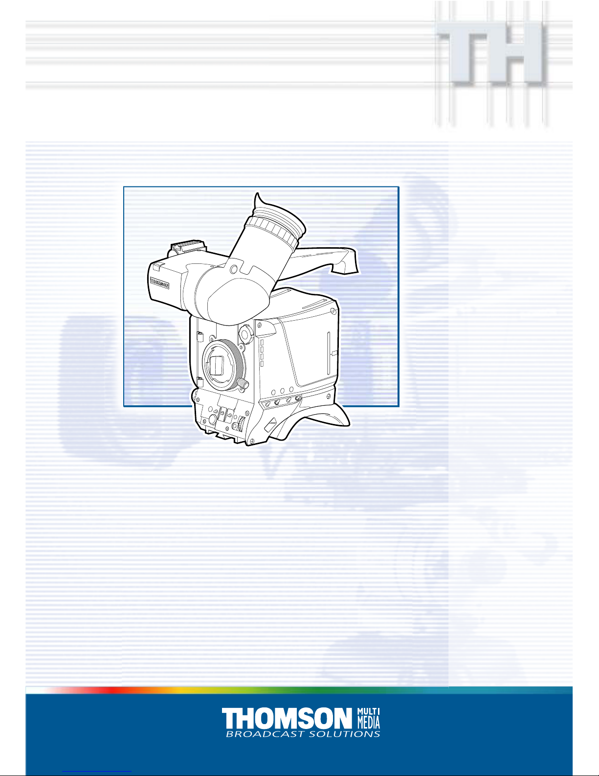
LDK 100LDK 100
LDK 100LDK 100
LDK 100
Multi-role Digital Camera Head
Technical Manual
3922 496 46761 St.03
Start
V
shift
Exp.
Tim
e
W
hite
B
al
C
lean
scan
Nom
. level
VTR
Save
Ext
Iris
Std
File
Power
on
Sm
art
Card
Power
off
1
Clear
2
ND 1/4
3 ND 1/16
4
N
D 1/64
Page 2

Für diese Unterlage behalten wir uns
alle Rechte vor (Gemäß DIN 34).
Technische Änderungen im Zuge der
Weiterentwicklung vorbehalten.
Copyright
FCC Class A Statement
Declaration of Conformity
Copying of this document and giving
it to others, and the use or communication of the contents thereof,
are forbidden without express authority. Offenders are liable to the
payment of damages. All rights are
reserved in the event of the grant of
a patent or the registration of a utility
model or design. Liable to technical
alterations in the course of further
development.
Toute communication ou reproduction de ce document, toute exploitation ou communication de son
contenu sont interdites, sauf autorisation expresse. Tout manquement à cette règle est illicite et
expose son auteur au versement de
dommages et intérêts. Tous nos
droits sont réservés pour le cas de la
délivrance d'un modèle d'utilité. Sous
réserve de modification au cours de
l'évolution technique.
© Thomson Multimedia Broadcast Solutions 2002
We, Thomson Broadcast Solutions Nederland B.V., Kapittelweg 10, 4827 HG Breda, The Netherlands declare under
our sole responsibility that this product is in compliance with the following standards:
EN60065
EN55103-1
EN55103-2
following the provisions of:
a. the Safety Directives 73/23//EEC and 93/68/EEC
b. the EMC Directives 89/336/EEC and 93/68/EEC
: Safety
: EMC (Emission)
: EMC (Immunity)
This product generates, uses, and can radiate radio frequency energy and if not installed and used in accordance with
the instructions, may cause interference to radio communications.
It has been tested and found to comply with the limits for a class A computing device pursuant to Subpart J of part 15
of FCC rules, which are designed to provide reasonable protection against such interference when operated in a commercial environment.
Operation of this product in a residential area is likely to cause interference in which case the user at his own expense
will be required to take whatever measures may be required to correct the interference.
Page 3

02.36.1 Technical Manual LDK 100 Camera Head i
LDK 100
Camera Head
Technical Manual
Contents
About This Manual ................................................ ii
Safety Instructions ........................................... 1-1
Safety Summary ................................................ 1-2
Cautions and Warnings ...................................... 1-2
Earthing ............................................................. 1-3
Installation ........................................................ 2-1
Packing/Unpacking ............................................ 2-2
Attaching an Adapter ......................................... 2-3
Detaching an Adapter ......................................... 2-3
Hardware Customization .................................... 2-4
Lens matching ................................................... 2-4
Connectors and Cables ...................................... 2-5
Specifications LDK 100 FT ................................ 2-8
Specifications LDK 100 IT ................................. 2-9
Specifications LDK 100 ITW .............................. 2-9
Dimensions ...................................................... 2-10
Replacements ................................................... 3-1
Introduction ........................................................ 3-2
Printed circuit boards ......................................... 3-2
Handgrip ............................................................ 3-3
Front unit ........................................................... 3-4
Adjustments ..................................................... 4-1
Introduction ........................................................ 4-2
Test Equipment ................................................. 4-3
Set-up Instructions ............................................. 4-3
White Shading Adjustment ................................. 4-4
Video ADC Automatic Calibration ....................... 4-4
Pre-processor Calibration ................................... 4-4
Sawtooth Calibration .. ........................................ 4-4
3200K Adjustment ............................................. 4-5
Flare Adjustment ................................................ 4-5
Software Download ............................................ 4-5
Video Gain Adjustment ...................................... 4-6
Extender Board .................................................. 4-6
Video Monitoring Adjustment ............................. 4-8
Diagnostics....................................................... 5-1
Diagnostic Messages ......................................... 5-2
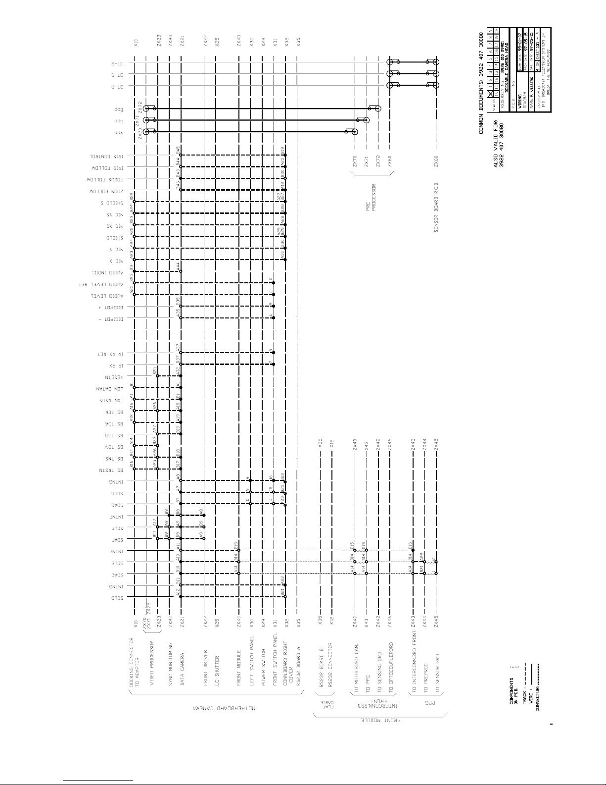
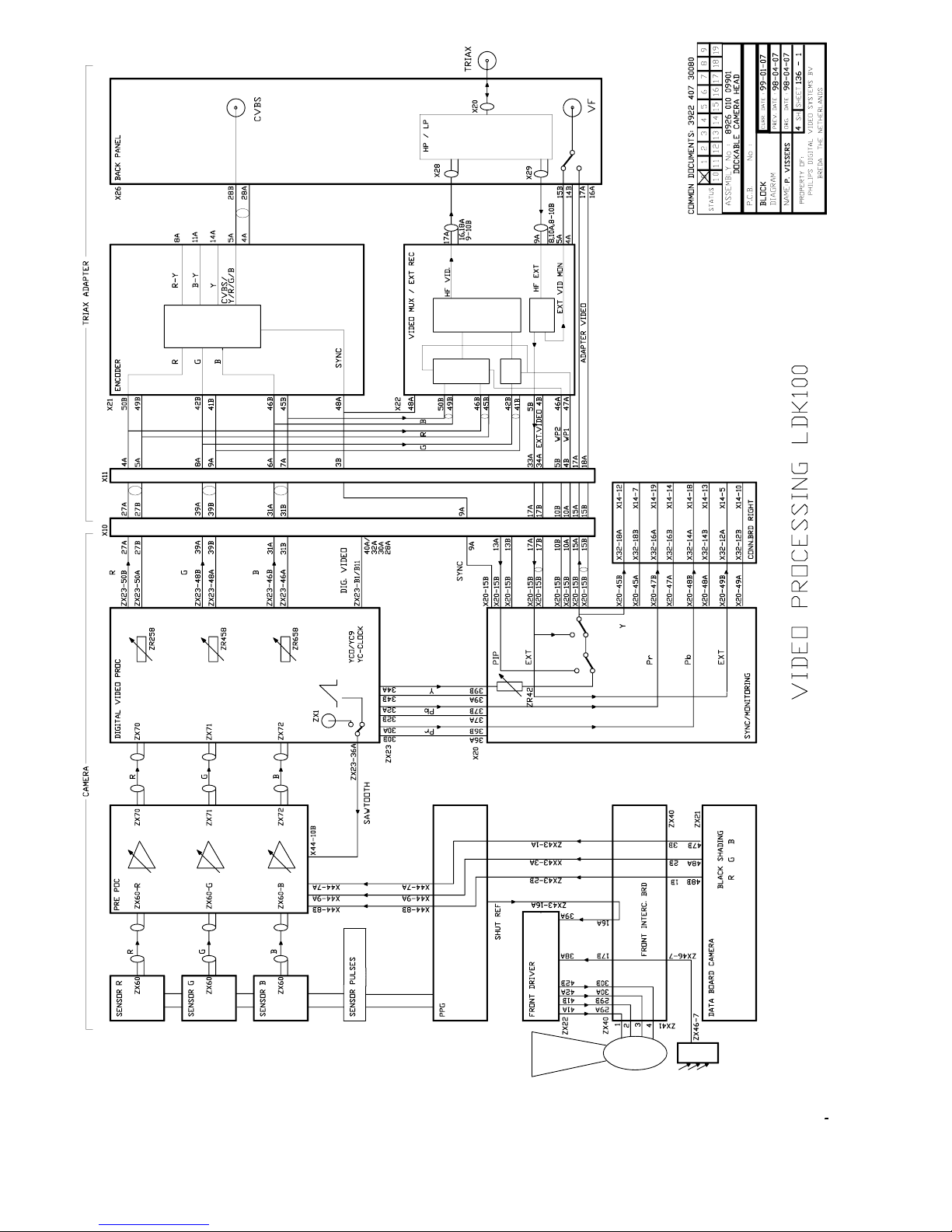
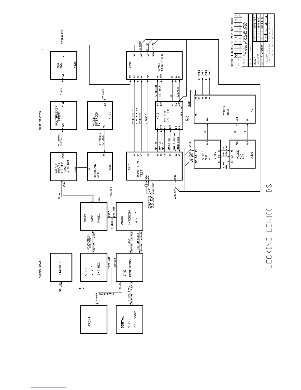
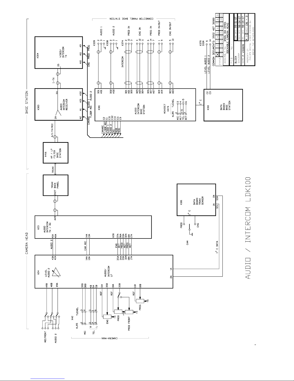
Wiring & Block Diagrams ................................ 6-1
Wiring Diagram Dockable Camera Head ............. 6-2
Block Diagram Dockable Camera Head.............. 6-6
Mechanical Exploded Views ........................... 7-1
Camera head Basic............................................ 7-2
Cover left assy................................................... 7-3
Cover right assy ................................................. 7-4
Hand grip assy ................................................... 7-5
Hand grip rubber assy ........................................ 7-6
Shoulder pad assy ............................................. 7-7
Front module PAL .............................................. 7-8
Front module PAL IT 800PX .............................. 7-9
Front module PAL ITW..................................... 7-10
Optical module PAL switchable ........................ 7-11
Optical module PAL IT 800PX ......................... 7-12
Optical module PAL ITW.................................. 7-13
Dockable camera head..................................... 7-14
Parts Lists ........................................................ 8-1
Page 4

ii Technical Manual LDK 100 Camera Head 02.36.1
About This Manual
Service policy
The LDK 100 is a sophisticated camera head containing
state-of-the-art electronic components which are
designed to provide long-life operation without the
need for maintenance. With this in mind, the service
policy of Thomson Multimedia Broadcast Solutions
endeavours to ensure that help will be quickly on hand
in the unlikely event of anything going wrong. The
guiding principles of the Thomson Multimedia Broadcast
Solutions first line maintenance philosophy are speed
and cost effectiveness. First line maintenance is
dedicated to keeping your camera operational, despite
a fault, by module replacement and the replacement of
minor mechanical parts by the user.
Purpose of this manual
The provision of correct information is the first step in
ensuring the operational integrity of the camera.
Information on the operation of the camera is to be
found in the Operators’s Manual.
This technical manual is an integral part of the service
policy. It ensures that you will be able to install and setup your camera to meet the requirements of your
environment. This information on the installation of the
camera is contained in Section 1 of the manual. The
remaining sections of the manual provide first line
service information so that suitably qualified service
personnel can detect and repair faults, normally by
module replacement.
Because of the complexity of some of the components,
second line service can only be carried out at the
specially equipped service centres and information
concerning second line maintenance is not supplied
in this manual.
Intended audience
The manual is intended as a guide to those with a
working knowledge of camera systems and installation
techniques. The first line detection and repair of faults
requires a general knowledge of test and measurement
techniques.
Structure of this manual
The manual is divided into four different sections:
Section 1: Safety Instructions
Outlines the safety precautions that must be taken
when using the camera.
Section 2: Installation.
Gives instructions on the integration of the camera into
the operating environment and the customization of
certain hardware functions
Section 3: Replacements.
Gives information on the replacement of components
at first line level.
Section 4: Adjustments.
Contains the adjustment procedures to be followed to
obtain the best performance.
Section 5: Diagnostics.
Contains diagnostic messages and block diagrams.
Section 6: Wiring & Block Diagrams
Section 7: Mechanical Exploded Views
Section 8: Parts Lists
Page 5

02.36.1 Technical Manual LDK 100 Camera Head iii
Identification and Status
To indicate the status of a drawing, a box with the
numbers 0 to 9 is shown in the bottom-right of the
drawing. The number that is crossed-out is the status
number of the drawing. For example, in the illustration
below, the status is 1.
A sticker is used on the units themselves to identify
them and to indicate their status. For example, in the
illustration below, the top line is the 12-digit number
that identifies the unit type.
The first four digits of the number on the second line
represent a date code (year, week); the next four digits
represent the serial number for that week.
The number in the grey area indicates the status of the
unit. The last two digits represent the number that will
be given to the next status. However, if these two
digits are contained in a box, then this is the current
status. For example, in the illustration above, the
current status of the unit is 01.
Line 1 3922 407 00000
Line 2 123456AA0101
Line 3 VR/0123456789
Line 1
This is the code number of the printed circuit board
assy. (PCB)
Line 2
This is the serial number of the PCB. The first 6 digits
and the 2 letters are for internal use. The last four digits
reperesent the date of the manufacturing: wwyy.
Example:
123456AA1402 means the PCB is manufactured in
week 14 of the year 2002.
Line 3
This is the status of the PCB.
The digit after the first slash is the status. If there is no
number before the slash, it means that the status is
less than 10, a 1 before the slash means the status
is between 10 and 19, a 2 before the slash means
between 20 and 29 etc.
Example:
- VR4567891012 means status 4
- VR3/78901234 means status 37.
0 1 2 3 4
5 6 7 8 9
3922 406 88991
00121107 00 01
Example of LDK number:
LDK 4501/01 means 8926 450 10101
LDK 4500/00 means 8926 450 00001
Numbers of printed circuit board assy
- 3922 406 xxxxx or 3922 407 xxxxx
Number (screened in PCB layout) of printed circuit
board assy: 3922 411xxxxx. (not a sparepart)
Page 6

iv Technical Manual LDK 100 Camera Head 02.36.1
Page 7

Safety Instructions Technical Manual LDK 100 - Camera Head 1-1
Section 1
Safety Instructions
This section outlines the precautions that must be taken into account when using the Camera Head.
Contents
Safety Summary ........................................................ 1-2
Cautions and Warnings ............................................. 1-2
Earthing ..................................................................... 1-3
Page 8

1-2 Technical Manual LDK 100 - Camera Head Safety Instructions
Safety Summary
This informaton is intended as a guide for trained and
qualified personnel who are aware of the dangers involved
in handling potentially hazardous electrical/electronic
equipment. It is not intended to contain a complete list of
all safety precautions which should be observed by
personnel in using this or other electronic equipment.
The installation, maintenance and service of this equipment
involves risks both to personnel and equipment and must
be performed only by qualified personnel exercising due
care.
Personnel engaged in the installation, operation,
maintenance or servicing of this equipment are urged to
become familiar with First Aid theory and practises.
During installation and operation of this equipment, local
building safety and fire protection standards must be
observed.
Before connecting the equipment to the power supply of
the installation, the proper functioning of the protective
earth lead of the installation needs to be verified.
Whenever it is likely that safe operation is impaired, the
apparatus must be made inoperative and secured against
any unintended operation. The appropriate servicing
authority must then be informed. For example, safety is
likely to be impaired if the apparatus fails to perform the
intended function or shows visible damage.
This product has been designed and tested according to
EN60065.
Cautions and Warnings
When performing service, be sure to read and comply with
the warning and caution notices appearing in the manuals.
Warnings indicate danger that requires correct procedures
or practices to prevent death or injury to personnel. Cautions
indicate procedures or practices that should be followed
to prevent damage or destruction to equipment or property.
WARNING
THE CURRENT AND VOLTAGES PRESENT IN THIS
EQUIPMENT ARE DANGEROUS. ALL PERSONNEL
MUST AT ALL TIMES FOLLOW THE SAFETY
REGULATIONS.
ALWAYS DISCONNECT POWER BEFORE REMOVING
COVERS OR PANELS.
ALWAYS DISCHARGE HIGH VOLTAGE POINTS
BEFORE SERVICING.
NEVER MAKE INTERNAL ADJUSTMENTS, PERFORM
MAINTENANCE OR SERVICE WHEN ALONE OR WHEN
FATIGUED.
IN CASE OF AN EMERGENCY ENSURE THAT THE
POWER IS DISCONNECTED.
ANY INTERRUPTION OF THE PROTECTION
CONDUCTOR INSIDE OR OUTSIDE THE APPARATUS,
OR DISCONNECTION OF THE PROTECTIVE EARTH
TERMINAL, IS LIKELY TO MAKE THE APPARATUS
DANGEROUS. INTENTIONAL INTERRUPTION IS
PROHIBITED.
FOR SAFETY REASONS THE CPU MUST BE MOUNTED
IN A 19-inch RACK WHICH HAS SAFETY COVERS
ACCORDING TO IEC65.
WHEN TWO CPUs ARE MOUNTED ABOVE EACH
OTHER THE MINIMUM DISTANCE BETWEEN THEM
MUST BE 50MM OR THE RACK MUST BE FORCE-AIR
COOLED.
USE ONLY FUSES OF THE TYPE AND RATING
SPECIFIED.
CAUTION
To prevent risk of overheating, ventilate the product
correctly.
Connect the product only to a power source with the
specified voltage rating.
Only connect a Triax cable from the LDK 6 camera
family to an LDK 6 CPU. Never connect it to any other
base station.
Never connect the Triax cable from a camera to a
CPU of a different family; never connect the LDK
family to the TTV family.
Do not allow system ground currents to exceed 1.5A
in the outer shield of the triax cable or 0.2A in other
cable shields.
It is strickly prohibited to short circuit the inner and
outer shields of a triax cable used to connect a
camera to a base station.
Page 9
Safety Instructions Technical Manual LDK 100 - Camera Head 1-3
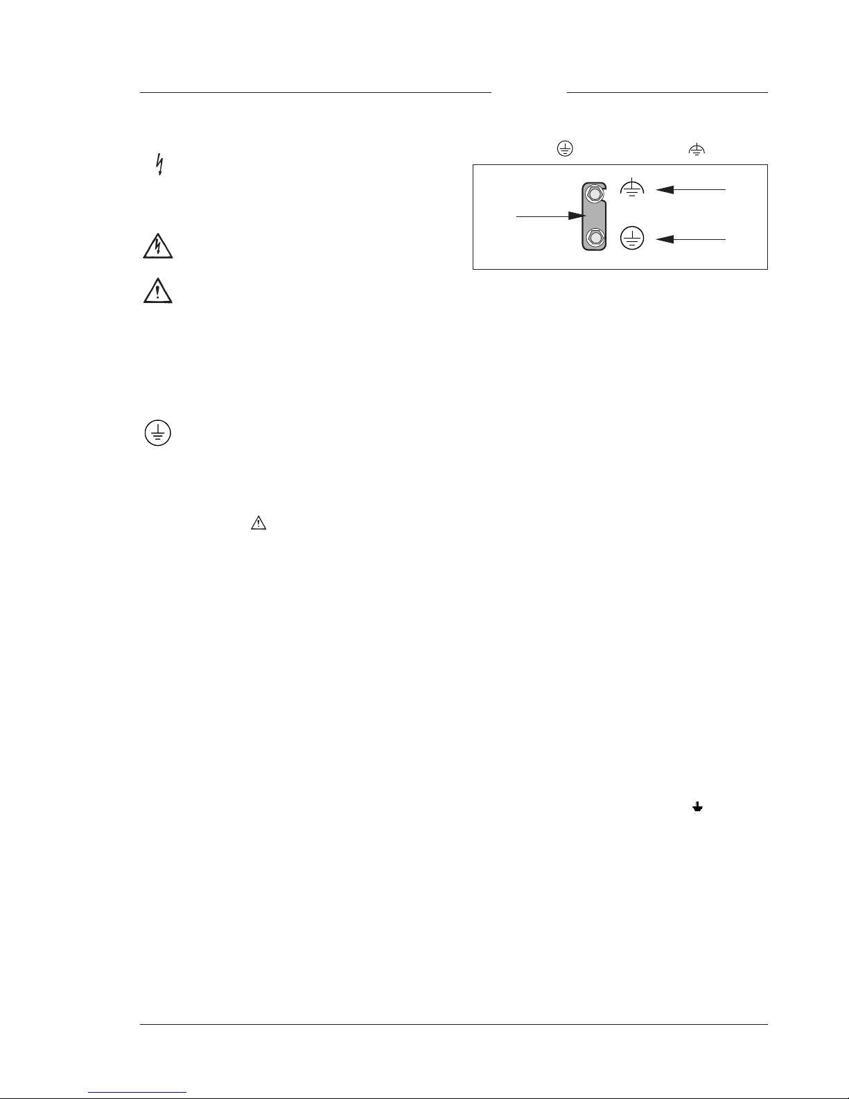
Symbol Colour Explanation
Red High voltage terminal at which a
voltage, with respect to an other
terminal, exists or may be
adjusted to 1000V or more.
Yellow/Black Live part.
Yellow/Black This marking indicates that the
operator must refer to an
explanation in the Instruction
Manual, or that a specific
component must be replaced by
the component specified in the
documentation for safety
reasons.
White/Black Protective earth (ground)
terminal.
Cathode ray tubes
Components marked
on the circuit diagram are critical
for safety and include those specified to comply with X-ray
emission standards for units using cathode ray tubes and
those specified for compliance with various regulations
regarding spurious radiation emission.
When servicing units that use cathode ray tubes (CRTs),
the cathode ray tubes themselves, the high voltage circuits
and related circuits are specifically chosen so that they
comply with recognized codes pertaining to X-ray emission.
Consequently, when servicing, replace the cathode ray
tubes and other parts with specified parts only. Do not
attempt to modify these circuits as any unauthorized
modification can increase the high voltage value and
cause X-ray emission from the cathode ray tube.
Handle the cathode ray tube only when wearing shatterproof
goggles and after discharging the high voltage completely.
Earthing
The rear of a CPU has two separate screw terminals for
protective earth (PE) and video earth (VE).
These are normally connected by a metal strap. The
protective earth terminal is internally connected to the
protective earth conductor of the power cable. If required,
the central earth connection wire of the studio can be
connected to terminal PE.
In normal circumstances the connection between the
protective earth and the video earth should not be broken.
The metal strap may be removed only if the studio (or OB
van) is equipped with separate protective and video earth
systems. Under these circumstances the video earth
terminal must be connected to the central functional earth
potential (video earth) of the studio. This earth potential
should have functional protective and noiseless earth
(FPE) qualities as stated in the VDE regulation 0800/part2.
A low impedance interconnection of both earth conductors
must be provided at the central studio earthing point.
WARNING
THE UNIT MUST ALWAYS BE CONNECTED TO
PROTECTIVE EARTH.
VE
PE
Metal
strap
Mains Lead Wiring for UK Users
The wires in the mains lead are coloured in accordance
with the following code:
GREEN AND YELLOW - EARTH
BLUE - NEUTRAL
BROWN - LIVE
As the colours of the wires in the mains lead of this
apparatus may not correspond with the coloured markings
identifying the terminals in your plug proceed as follows:
• The wire coloured GREEN AND YELLOW must be
connected to the terminal on the plug marked with the
letter E or by the safety earth symbol
or coloured
GREEN or GREEN AND YELLOW.
• The wire coloured BROWN must be connected to the
terminal marked with the letter L or coloured RED.
• The wire coloured BLUE must be connected to the
terminal marked with the letter N or coloured BLACK.
Ensure that your equipment is connected correctly - if you
are in any doubt consult a qualified electrician.
Page 10

1-4 Technical Manual LDK 100 - Camera Head Safety Instructions
Page 11

Installation Technical Manual LDK 100 Camera Head 2-1
Section 2
Installation
This section provides information which is relevant when the camera is to be used for the first time.
Packing and unpacking instructions together with information on the integration of the camera into
your studio system are provided. The procedures for the customization of certain hardware functions
and connector information is also provided.
Contents
Packing/Unpacking ............................................ 2-2
Attaching an Adapter ......................................... 2-3
Detaching an Adapter ......................................... 2-3
Hardware Customization .................................... 2-4
Lens matching ................................................... 2-4
Connectors and Cables ...................................... 2-5
Specifications LDK 100 FT ................................ 2-8
Specifications LDK 100 IT ................................. 2-9
Specifications LDK 100 ITW .............................. 2-9
Dimensions ...................................................... 2-10
Page 12

2-2 Technical Manual LDK 100 Camera Head Installation
Packing/Unpacking
Inspect the shipping container for evidence of damage
immediately after receipt. If the shipping container or
cushioning material is damaged, it should be kept until
the contents of the shipment have been checked for
completeness and the units have been checked
mechanically and electrically.
The shipping container should be placed upright and
opened from the top. Remove the cushioning material
and lift out the contents.
The contents of the shipment should be checked
against the packing list. If the contents are incomplete,
if there is mechanical damage or defect, or if the units
do not perform correctly when unpacked, notify your
Thomson Multimedia Broadcast Solutions sales or
service centre within eight days. If the shipping
container shows signs of damage or stress, notify the
carrier as well.
If a unit is being returned to Thomson Multimedia
Broadcast Solutions for servicing, try to use the
containers and materials of the original packaging.
Attach a tag indicating the type of service required,
return address, model number, full serial number and
the return number which will be supplied by your
Thomson Multimedia Broadcast Solutions service
centre.
If the original packing can no longer be used, the
following general instructions should be used for
repacking with commercially available materials:
a. Wrap unit in heavy paper or plastic.
b. Use strong shipping container.
c. Use a layer of shock-absorbing material around all
sides of the unit to provide firm cushioning and
prevent movement inside container.
d. Seal shipping container securely.
e. Mark shipping container FRAGILE to ensure careful
handling.
Page 13

Installation Technical Manual LDK 100 Camera Head 2-3
Attaching an Adapter
The LDK 100 Camera head is a multi-role camera head
that can be used with various adapters. To attach an
adapter to the camera proceed as follow:
Caution
Be extremely careful with the connectors between
the camera head and the adapter. Do not allow the
guide pins to damage the pins of the connector.
Caution
Follow these steps in the order given. Tightening
the screws in the wrong order could result in
mechanical damage to the camera.
a. Using the rail 1 on the bottom of the camera head
as a guide, fit the guide pins 2 on either side of the
connector and the guide pin 3 at the top rear of the
camera head into the corresponding slots of the
adapter.
b. First, tighten the two horizontal screws 4 on the
top of camera.
c. Next, tighten the two horizontal screws 5 at the
front of the camera.
d. Lastly, tighten the vertical screw 6 in the handle of
the camera.
Detaching an Adapter
To detach an adapter from the camera head follow the
steps for attaching it in the reverse order.
Caution
Loosening the screws in the wrong order could
result in mechanical damage to the camera.
Note
The procedure is given for the Triax adapter
LDK 5400. Follow the same procedure for the other
adapters.
1
2
3
4
5
6
Page 14
2-4 Technical Manual LDK 100 Camera Head Installation
The camera head is delivered in a ready-to-use state,
however, there are occasions when it might be
necessary to re-adjust some functions after, for
example, fitting a new lens.
A large number of functions can be set-up using the
control facilities of the menu system. In addition to this
software set-up there are some functions which can be
selected or adjusted internally in the camera.
Refer to the next chapters for instructions.
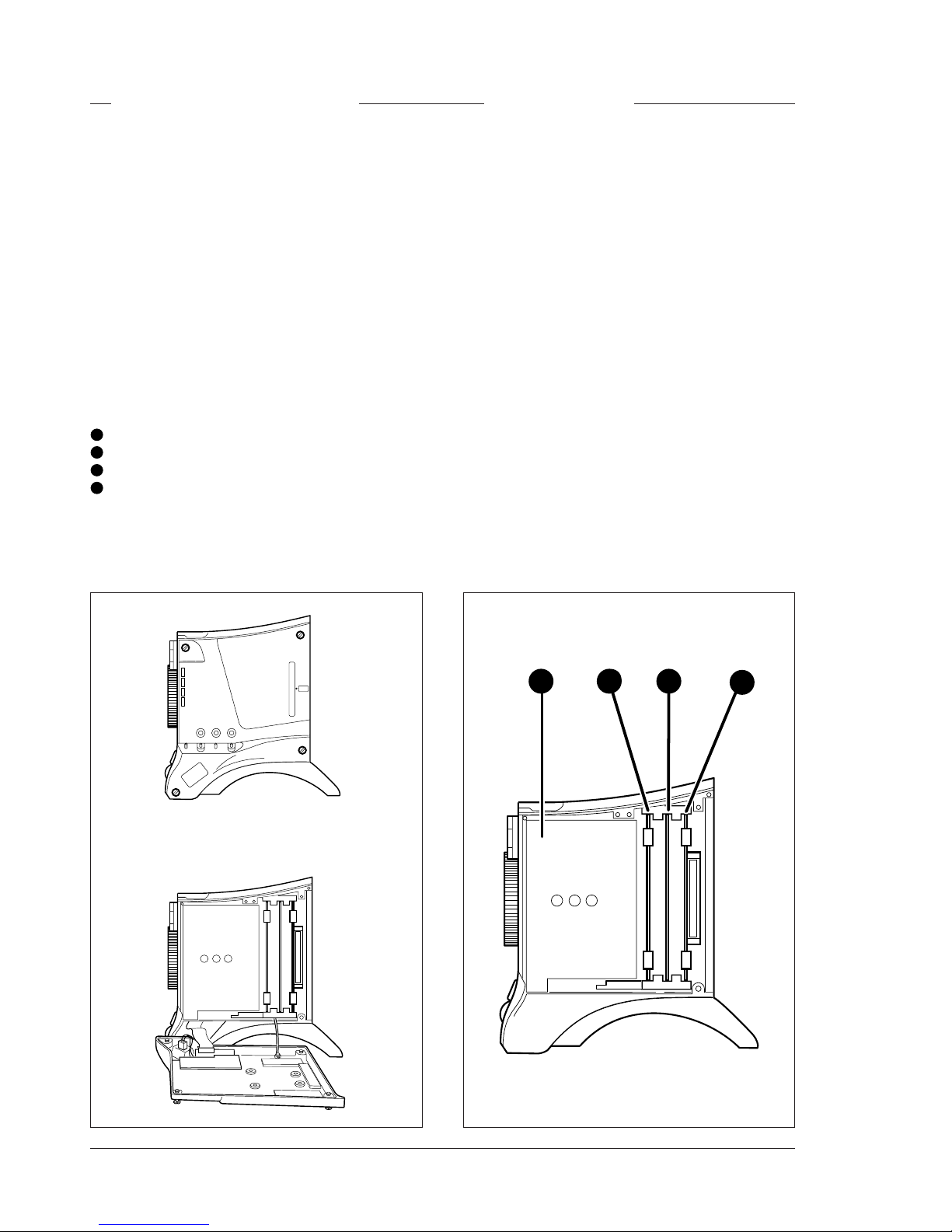
Location of boards
Unscrew the four screws on the left side panel and
swing down the cover.
1
Front module
2
Sync monitoring board
3
Data board
4
Front driver board
Hardware Customization Lens matching
When a camera is supplied with a lens it is not
necessary to perform any of the following adjustments
as the lens is already matched to the camera. However,
if you wish to change to a different type of lens or the
lens is not supplied with your camera, back focus,
white shading and auto iris adjustment procedures
may have to be performed.
• Colour balance.
If required, perform the gain adjustment of the
preprocessor board and/or white shading adjustment
procedures, described in section 3.
• Auto Iris Adjustment
If a different lens either works too slow or overshoots
too much with the auto iris control, adjust the
potentiometer on the lens to obtain acceptable
operation. Refer to the lens documentation.
• Back Focus Adjustment
To adjust the back focus of the lens refer to the
documentation of the lens.
1 2 3
4
Page 15
Installation Technical Manual LDK 100 Camera Head 2-5
Connectors and Cables
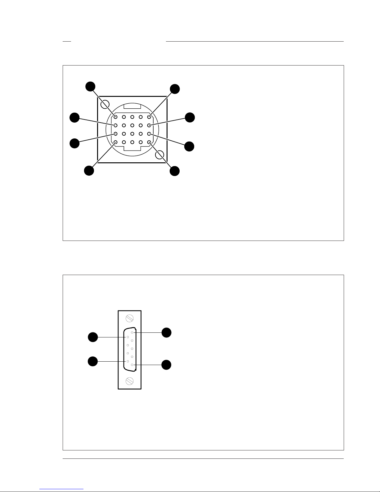
RS232 connector
1. SPARE
2. RS-RXD
3. RS-TXD
4. RS-DTR
5. RS-DGND
6. RS-DSR
7. RS-RTS
8. RS-CTS
9. +12V
1
9
5
6
1. -80V
2. n.c.
3. GND
4. INTN-D
5. vf ext video
6. n.c.
7. vf video ret
8. SDA-D
9. SCL-D
10. vf ext video ret
11. GND
12. vf video
13. Pb vf ret
14. Pr vf ret
15. GND
16. +batt
17. +batt
18. Pb vf
19. Pr vf
20. shield
20-pin female; panel view
Viewfinder connector
9-pin female; panel view
1
6
5
10
11
15
20
16
Page 16
2-6 Technical Manual LDK 100 Camera Head Installation
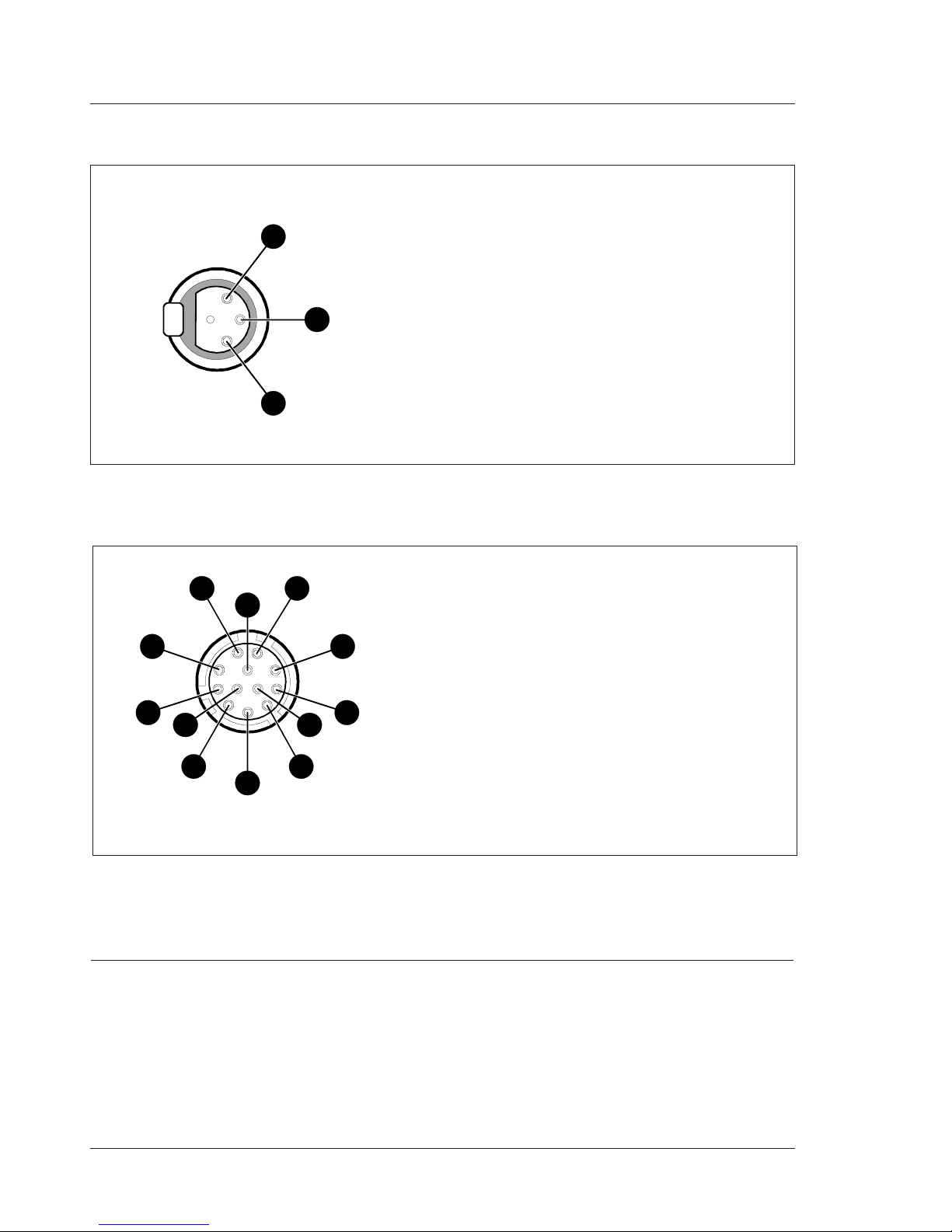
1. Ext. Video On/Off
2. VTR Trigger Switch
3. -batt
4. Momentary Iris
5. IrisControl
6. + batt
7. Iris Follow
8. Lens Servo
9. Range Extender
10. Zoom Follow
11. Focus follow*
12. Spare
* not standard on lens
Hirose 12-pin female; panel view
Lens connector
5
6 4
11
3
2
12
7
8
9
10
1
1. Audio Screen
2. Audio In
3. Audio Return
Microphone impedance >200 ohm
Sensitivity remote controlled via base
station:
range: -70 to -28 dBm
Signal at pin 2 of audio input is in phase with
signal at pin 2 of audio output on Base
station
XLR 3-pin female
Audio microphone connector
1
2
3
Panel Connector Type Part number Cable part number
Viewfinder 20-pin Hirose female 5322 214 12544 5322 320 12159 male
Lens 12-pin Hirose female 5322 265 10389 5322 265 41208 male
Audio Mic 3-pin XLR female 5322 267 40523 -Rs 232 9-pin male -- --
Page 17

Installation Technical Manual LDK 100 Camera Head 2-7
A row name B row name C row name D row name
1 lon data 1 lon data N 1 GND 1 + batt
2 SDA_C 2 SCL_C 2 GND 2 + batt
3 INTN_C 3 audio indication 3 GND 3 + batt
4 AB batt sense 4 batt sense 4 GN D 4 + batt
5 adpt id 0 5 adpt id 1 5 GND 5 + batt
6 adpt id 2 6 adpt id 3 6 GND 6 + batt
7 cam id 0 7 cam id 1 7 GND 7 + batt
8 48 kHz 8 PIP 8 GND 8 + batt
9 sync 9 blanking 9 GND 9
10 white pulse 1 10 white pulse 2 10 GND 10
11 colour framing 11 frame reset 11 GND 11
12 BS_TDA 12 H lock 12 GND 12
13 PIP video 13 PIP video ret 13 GND 13
14 BS_TDV 14 BS_TMS 14 GND 14
15 adapter vf video 15 adapter vf video ret 15 GND 15
16 BS_TCK 16 BS_TRSTN 16 GND 16 GND
17 ext video 17 ext video ret 17 GND 17 GND
18 -5V 18 -5V 18 -5V 18 -5V
19 +5V 19 +5V 19 +5V 19 +5V
20 +3.3V 20 +3.3V 20 +3.3V 20 +3.3V
21 +5VD 21 +5VD 21 +5VD 21 +5VD
22 shield 22 shield s 22 GND 22 GND
23 mic X 23 mic Xs 23 GND 23 GND
24 mic Y 24 mic Ys 24 GND 24
25 audio level 25 audio level ref 25 GND 25
26 power switch 26 n.c 26 GND 26
27 R 27 R ret 27 GND 27
28 YC clock 28 YC clock ret 28 GND 28
29 G 29 G ret 29 GND 29
30 YC9 30 YC9 ret 30 GND 30
31 B 31 B ret 31 GND 31
32 YC8 32 YC8 ret 32 GND 32
33 YC7 33 YC7 ret 33 GND 33
34 YC6 34 YC6 ret 34 GND 34 housing
35 YC5 35 YC5 ret 35 GND 35 housing
36 YC4 36 YC4 ret 36 GND 36 housing
37 YC3 37 YC3 ret 37 n.c 37
38 YC2 38 YC2 ret 38 n.c 38
39 YC1 39 YC1 ret 39 -80V 39
40 YC0 40 YC0 ret 40 -80V 40
Docking connector camera
A
B
C
D
40
1
160-pin male; panel view
Page 18

2-8 Technical Manual LDK 100 Camera Head Installation
Specifications LDK 100 FT
General data
Power requirements 12V dc (11.0 to 17.0)
Power consumption 26.5 W (+ VF)
Operating temperatures
0°C to +40°C (32°F to +104°F)
Storage temperatures
-20°C to +60°C (-4°F to +140°F)
Weight (approx.)
4.9 kg (14.1 lb) incl. 1.5-inch VF and triax adaptor
Camera section
Pick-up device
3 x 2/3-inch Philips Frame Transfer Sensors or
3 x 2/3-inch switchable DPM Sensors
Picture elements
NTSC: 1000(h) x 498(v)
PAL: 1000(h) x 594(v)
Digital quantization
12 bits A/d
Digital signal processing
18 MHz and 36 MHz, >20 bits accuracy
Sensitivity
2000 lux (186 ft cd) at F9.0 reflectance 89.9%
Minimum illumination
Approx. 1 lux at F 1.4 and +36 dB gain
Exposure control
Down to 1/1000
Clean scanning
NTSC: between 61.1 and 151.0 Hz
PAL: between 51.0 and 103.0 Hz
Optical system
F1.4 with quartz filter
Optical filters
Clear; 1/4 ND, 1/16 ND, 1/64 ND
Modulation depth
Typical: 70% at 5Mhz
S/N ratio
Typical: 60 dB PAL and 62 dB NTSC
Registration
<25 ns (0.05%) in all zones, without lens
Dynamic range
>600%
Gain
-6dB to +36dB in 3dB steps (user defined presets)
Page 19

Installation Technical Manual LDK 100 Camera Head 2-9
Specifications LDK 100 IT
General data
Power requirements 12V dc (11.0 to 17.0)
Power consumption 26.5 W (+ VF)
Operating temperatures
-20°C to +40°C (-4°F to +113°F)
Storage temperatures
-20°C to +60°C (-4°F to +140°F)
Weight (approx.)
4.9 kg (14.1 lb) incl. 1.5-inch VF and triax adater
Camera section
Pick-up device
3 x 2/3-inch Interline Transfer CCD
Picture elements
NTSC: 813(h) x 503(v)
PAL: 813(h) x 585(v)
Smear
-120 dB typical
Digital quantization
12 bits A/D
Digital signal processing
18 MHz and 36 MHz, >20 bits accuracy
Sensitivity
2000 lux at F11 (typical)
Minimum illumination
Approx. 0.25 lux at F 1.4 and +42 dB gain
Exposure control
Down to 1/2000
Clean scanning
NTSC: between 60.1 and 151.0 Hz
PAL: between 50.1 and 103.0 Hz
Optical system
F1.4 with quartz filter
Optical filters
Clear; 1/4 ND, 1/16 ND, 1/64 ND
Modulation depth
Typical: 50% typical at 5Mhz
S/N ratio
Typical: 60 dB PAL and 62 dB NTSC
Registration
<25 ns (0.05%) in all zones, without lens
Dynamic range
>500%
Gain
-6dB to +42dB in 3dB steps (user defined presets)
Vertical resolution
Pal 450 TV lines (500 TV lines in EVR)
NTSC 400 TV lines (450 TV lines in EVR)
EVR= Extended Vertical Resolution mode
Specifications LDK 100 ITW
General data
Power requirements 12V dc (11.0 to 17.0)
Power consumption 26.5 W (+ VF)
Operating temperatures
-20°C to +45°C (-4°F to +113°F)
Storage temperatures
-20°C to +60°C (-4°F to +140°F)
Weight (approx.)
4.9 kg (14.1 lb) incl. 1.5-inch VF and triax adapter
Camera section
Pick-up device
3 x 2/3-inch Interline Transfer CCD
Aspect Ratio: switchble 16:9 and 4:3
Picture elements
NTSC: 1038(h) x 504(v)
PAL: 1038(h) x 594(v)
Smear
-120dB (typical)
Digital quantization
12 bits A/D
Digital signal processing
18 MHz and 36 MHz, >20 bits accuracy
Sensitivity
2000 lux at F11 (typical)
Minimum illumination
Approx. 0.25 lux at F 1.4 and +42 dB gain
Exposure control
Down to 1/2000
Clean scanning
NTSC: between 60.1 and 151.0 Hz
PAL: between 50.1 and 103.0 Hz
Optical system
F1.4 with quartz filter
Optical filters
Clear; 1/4 ND, 1/16 ND, 1/64 ND
Modulation depth
Typical: 50% typical at 5Mhz
S/N ratio
Typical: 60 dB PAL and 62 dB NTSC
Registration
<25 ns (0.05%) in all zones, without lens
Dynamic range
>500%
Gain
-6dB to +42dB in 3dB steps (user defined presets)
Vertical resolution
Pal 450 TV lines (500 TV lines in EVR)
NTSC 400 TV lines (450 TV lines in EVR)
EVR= Extended Vertical Resolution mode
Page 20
2-10 Technical Manual LDK 100 Camera Head Installation
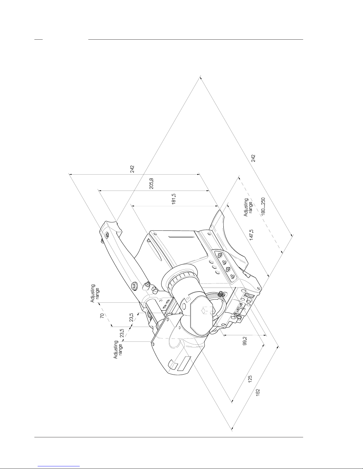
Dimensions
Page 21

Replacements Technical Manual LDK 100 - Camera Head 3-1
Section 3
Replacements
This section gives information on the procedures to follow when replacing printed circuit boards and
mechanical components at first line level.
Contents
Introduction ........................................................ 3-2
Printed circuit boards ......................................... 3-2
Handgrip ............................................................ 3-3
Front unit ........................................................... 3-4
Page 22
3-2 Technical Manual LDK 100 - Camera Head Replacements
Introduction
The instructions given in this section are restricted to
those modules which can be replaced at the first line
service level. These modules include:
• The printed circuit boards
• The handgrip
• The front unit
After a printed circuit board has been replaced it is
sometimes necessary to carry out adjustments to
match the new boards to your camera and so maintain
the performance levels. The relevant adjustment
procedures are given in Section 3.
The procedures for removing the modules should be
followed in reverse order when remounting the units.
Printed circuit boards
Gaining access to the boards
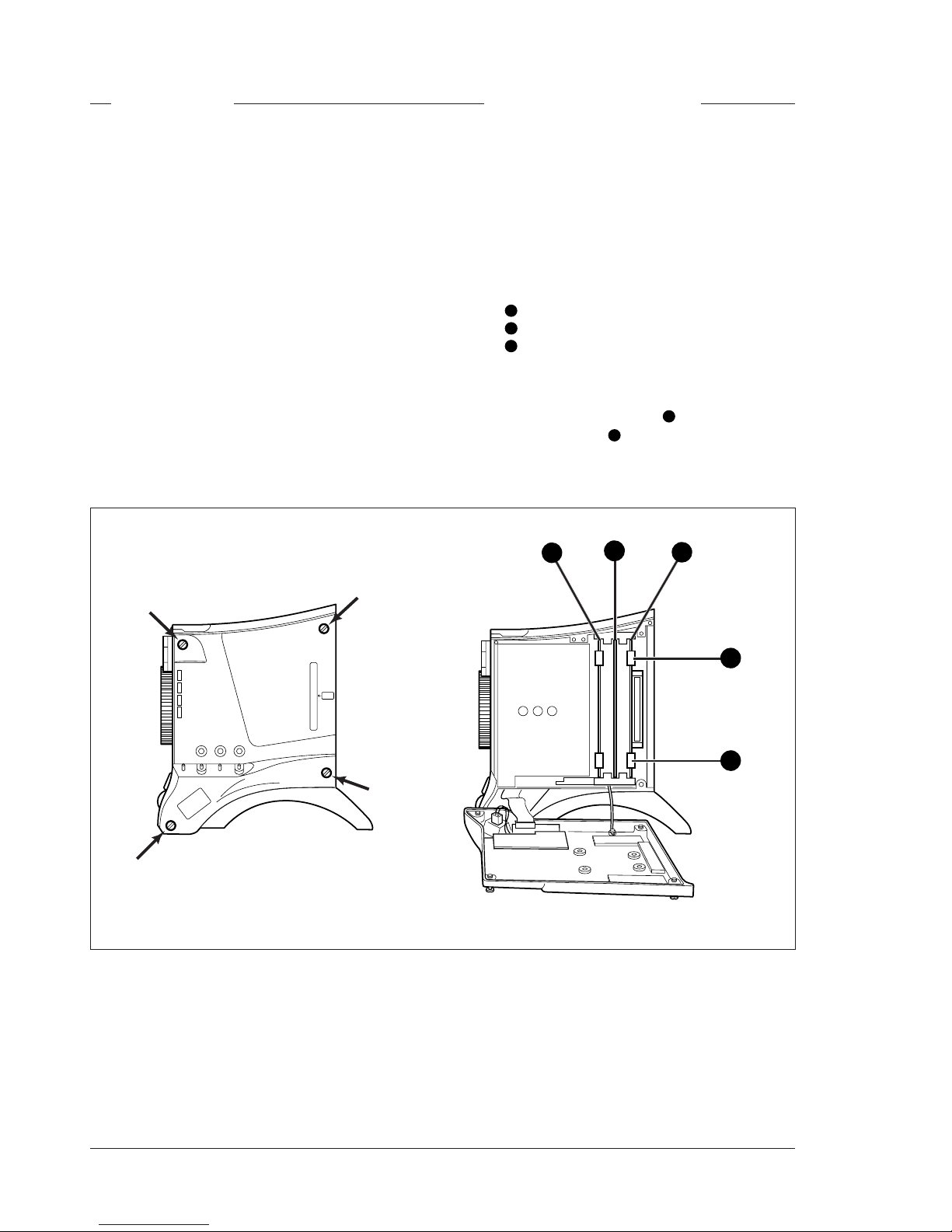
To access the printed circuit boards remove the left
side cover of the camera head as follows:
a. Unscrew the four screws on the left side panel.
b. Swing down the cover.
Location of boards
The boards in the camera head are numbered as
follows:
1
Sync monitoring board
2
Data board
3
Front driver board
Removing a board
To remove a printed circuit board proceed as follows:
a. Pull up the top print ejector 4 and pull down the
bottom print ejector 5 to release the printed circuit
board from its connector.
b. Pull horizontally on these ejectors to slide the
board clear of the camera.
1
2
3
4
5
Page 23
Replacements Technical Manual LDK 100 - Camera Head 3-3
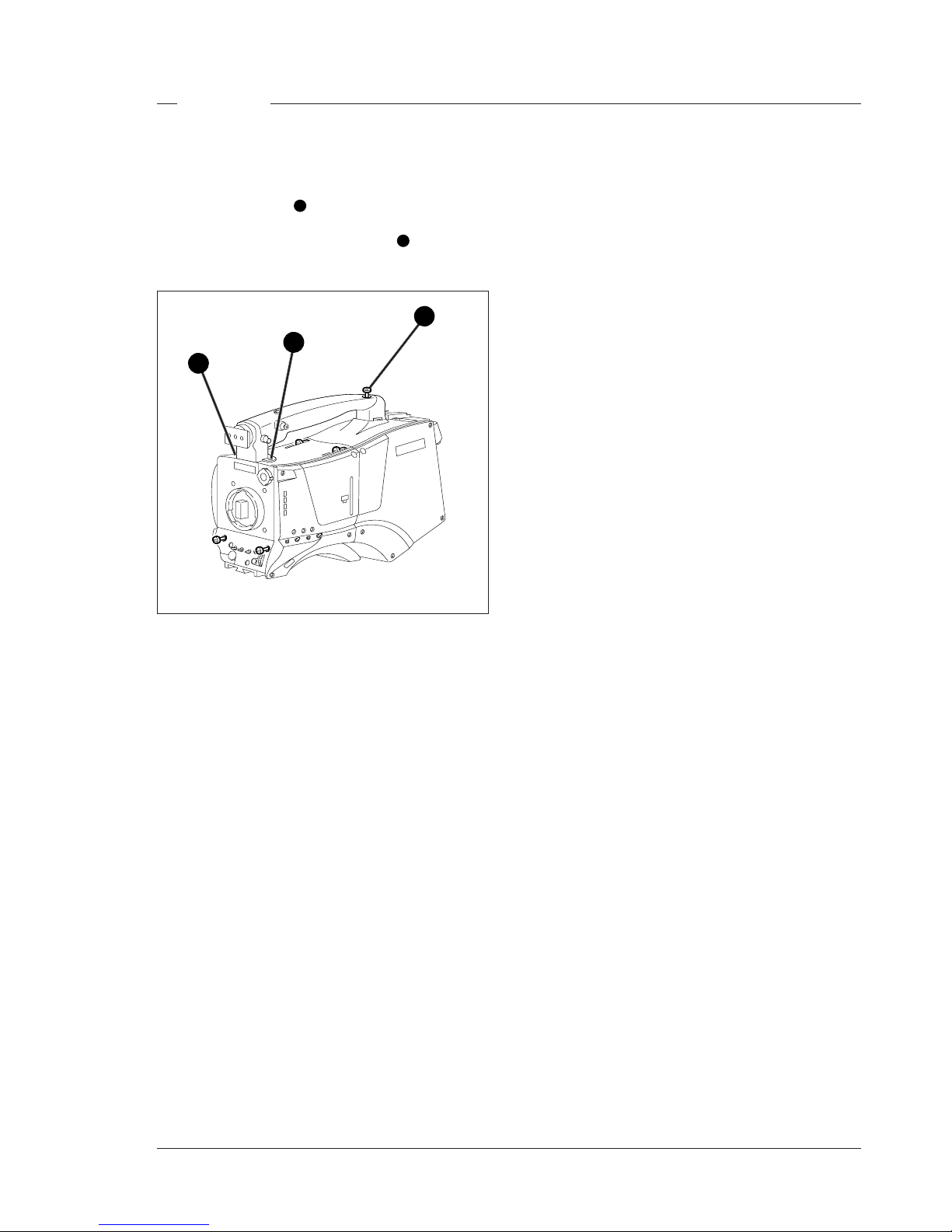
To remove the handgrip proceed as follows:
a. Remove the 1.5 inch viewfinder from its support
bracket on the handgrip.
b. Loosen the screw 1 securing the handgrip to the
top of the adapter.
c. Loosen the two socket head screws 2 securing the
handgrip to the front of the camera.
Handgrip
1
2
2
Page 24
3-4 Technical Manual LDK 100 - Camera Head Replacements
To remove the front unit the following steps have to be
carried out:
• Remove the handgrip
• Detach the adapter
• Remove the camera left side cover
• Remove the camera right side cover
• Remove DVP board
• Remove the front unit
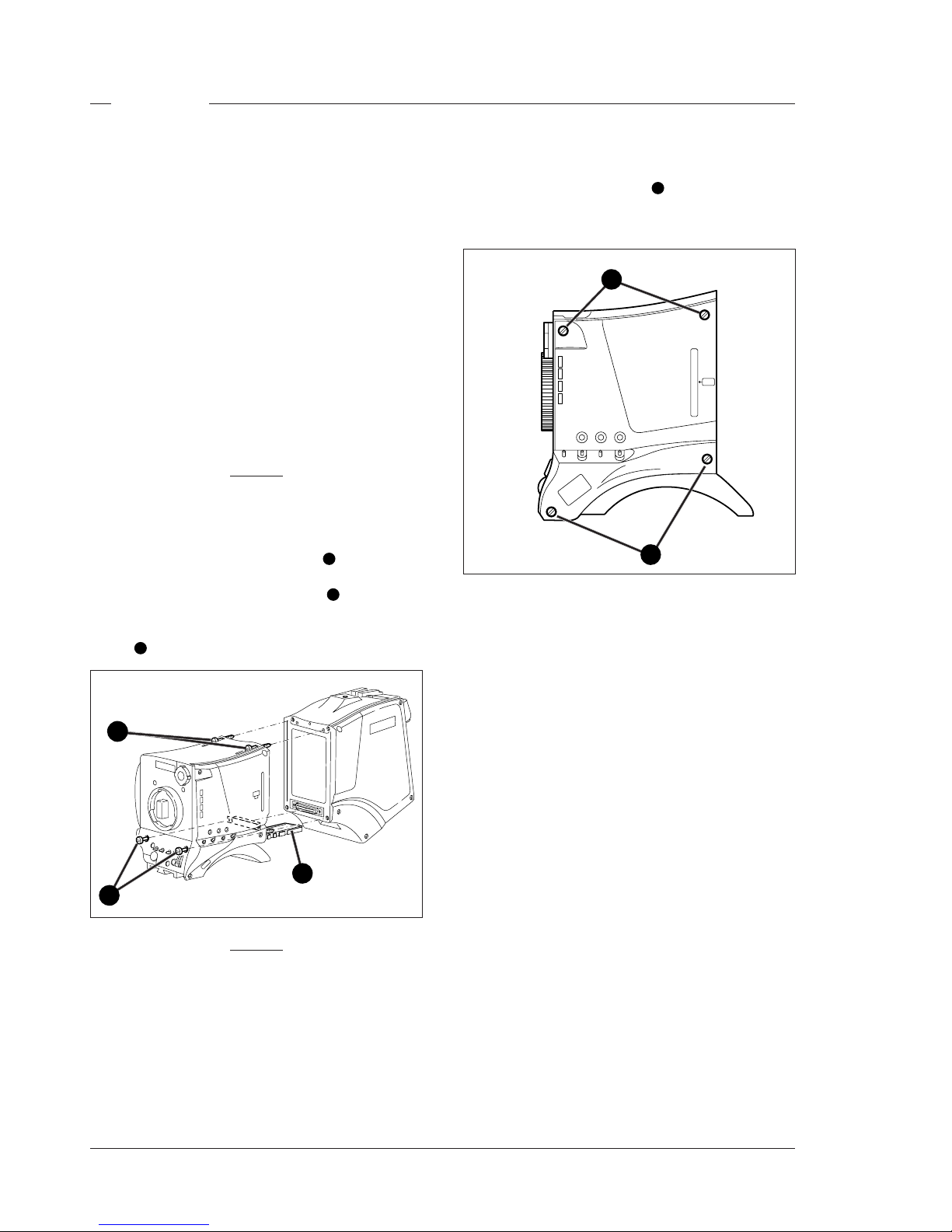
Removing the handgrip
To detach the handgrip follow the instructions given on
the previous page.
Detaching the adapter
To detach the adapter from the camera proceed as
follows:
Caution
Follow these steps in the order given. Loosening the
screws in the wrong order could result in
mechanical damage to the camera.
a. Loosen the two horizontal screws 1 at the front of
the camera.
b. Loosen the two horizontal screws 2 on the top of
camera.
c. Slide the adapter away from the camera along the
rail 3 at the bottom of the camera.
Front unit
Opening the left side cover
To open the left side cover proceed as follow:
a. Loosen the four screws 1 at the front of the
camera.
b. Swing down the cover
Caution
When reattaching the adapter be extremely
careful with the connectors between the camera
head and the adapter. Do not allow the guide pins
to damage the pins of the connector.
1
1
1
2
3
Page 25
Replacements Technical Manual LDK 100 - Camera Head 3-5
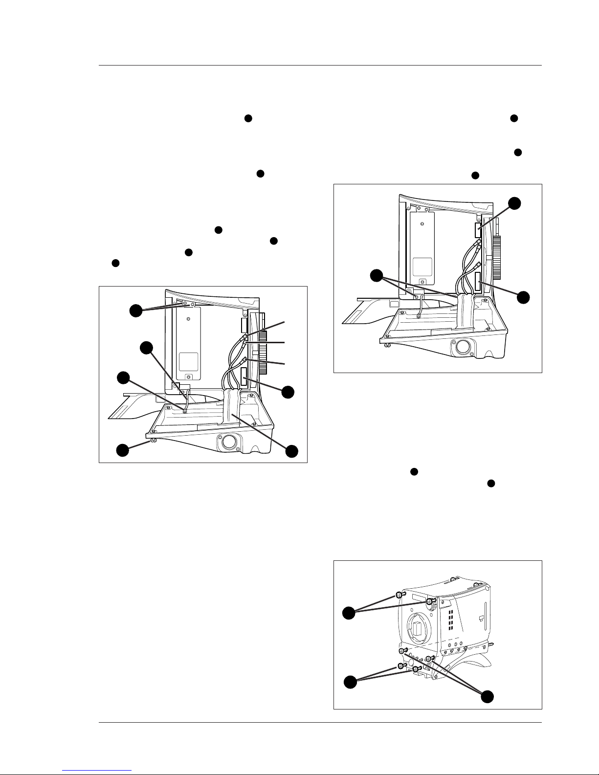
Opening the right side cover
To remove the right front cover proceed as follows:
a. Unscrew the four retaining screws 1 and swing the
right front cover down.
b. Disconnect the B, R and G coax cables from the
DVP board using the correct tool (part no. 5322 395
10802)
c. Unscrew the two top retaining screws 2 of the DVP
board and swing the board downwards.
d. Reach in behind the board and disconnect the flat
cable from the connector at the bottom of the
board.
e. Disconnect the flat cable 3 that comes from the
cover, from the motherboard connector 4.
f. Loosen the screw 5 and remove the retaining tie
6
that restrains the cover.
g. Remove the cover.
B
R
G
x4
Removing the DVP board
To remove the DVP board proceed as follows:
h. Unscrew the two bottom retaining screws 7 of the
DVP board from the plastic clips and remove the
board.
i. Unscrew and disconnect the top connector 8 from
the DVP board.
j. Unscrew the bottom connector 9.
Removing the front unit
To remove the front unit proceed as follows:
a. To ease the removal of the front unit remove the
adapter screws 1 completely.
b. Unscrew the four retaining screws 2 of the front
unit.
c. Move the front unit slightly upwards and forward
and disconnect the flat cable that comes from the
front from the connector on the connector board of
the camera.
d. Remove the front unit.
Clear Clear
A
1
Star 4P
ND1/4
B
2
Star 6P
ND 1/16
C
33
Soft focus
ND 1/64
D
4
1
1
2
2
2
3
4
5
6
7
8
9
Page 26

3-6 Technical Manual LDK 100 - Camera Head Replacements
Page 27

Adjustments Technical Manual LDK 100 - Camera Head 4-1
Section 4
Adjustments
This section contains the adjustment procedures to be followed to obtain the best performance from
the camera. These procedures need only be used if, following a module replacement, the camera
does not perform according to specifications.
Contents
Introduction ........................................................ 4-2
Test Equipment ................................................. 4-3
Set-up Instructions ............................................. 4-3
White Shading Adjustment ................................. 4-4
Video ADC Automatic Calibration ....................... 4-4
Pre-processor Calibration ................................... 4-4
Sawtooth Calibration .. ........................................ 4-4
3200K Adjustment ............................................. 4-5
Flare Adjustment ................................................ 4-5
Softw are Download ......................................... 4-5
Video Gain Adjustment ...................................... 4-6
Extender Board .................................................. 4-6
Video Monitoring Adjustment ............................. 4-8
Page 28

4-2 Technical Manual LDK 100 - Camera Head Adjustments
Introduction
This camera is factory tested and adjusted for operational
use. Under normal circumstances, the internal automatic
calibration procedures do not need to be started and the
internal potentiometers do not need to be adjusted.
There are two situations that might require some
realignment of the camera:
a. When a lens is fitted.
b. When a printed circuit board has been replaced.
When a lens is fitted the following alignment procedures
should be carried out in the order given:
1. Run the internal 3200K calibration procedure.
2. Adjust the white shading via the menu system.
3. Adjust the flare.
4. Adjust the back focus (see lens manual for this
adjustment).
If a printed circuit board is replaced, refer to table 3-1 to
see which adjustments must be carried out to realign
the camera. For a particular board, carry out the
procedures in the order given.
If it is discovered that the camera is misaligned, the
following procedures are given as a guide for competent
service personnel, who have a thorough knowledge of
the camera and have the use of calibrated equipment,
to realign the camera.
If no improvement can be achieved or an adjustment is
out of range, please contact your local supplier or the
nearest Thomson Multimedia Broadcast Solutions
Service Centre.
The camera head adjustment procedures are designed
as separate units. Within a numbered procedure do not
change the position of switches or jumpers unless
instructed to do so in the procedure.
These adjustment procedures are for the Camera
Head. However, for practical purposes the Triax Adapter
is used together with the camera head to facilitate some
measurements. Other adapters can be used for these
measurements.
Table 3-1 Adjustment procedures on board replacement
Printed Circuit Board
Digital video board
Pre-processor board
Lens plate assemble
Data Board
Sync. / monitoring board
Viewfinder PCBs
Adjustment Procedure
1. Video ADC automatic calibration (internal)
2. Sawtooth calibration (internal)
3. Video gain adjustment
1. Pre-processor calibration (internal)
1. 3200K adjustment
2. White shading adjustment
3. Flare adjustment
1. Software download
1. Video monitoring adjustment
1. Viewfinder alignment
Page 29

Adjustments Technical Manual LDK 100 - Camera Head 4-3
Set-up Instructions
Before carrying out any adjustments the following steps
are recommended:
• Attach an adapter to the camera.
• Install the camera on a tripod.
• Attach the lens and the necessary cables.
• Allow the camera to warm-up.
CAUTION:
Do not attempt to improve camera performance
by adjusting individual potentiometers, jumpers or switches
as this may lead to complete misalignment of the camera.
CAUTION:
Do not realign individual potentiometers, jumpers or switches
not mentioned in this chapter or earlier in this manual.
These adjustment points are for factory use only.
CAUTION:
Switch off the power supply to the camera
before removing or replacing printed circuit boards.
Test Equipment
The following is a list of equipment required to carry out
the adjustment procedure:
• Set of board extenders LDK 5820/01
• Oscilloscope (with cursor measurement)
• Spotlight 3200K
• Focus test chart
• Black hole test chart
• White PortaPattern test chart
• White 3200K test chart
• Waveform monitor
Page 30

4-4 Technical Manual LDK 100 - Camera Head Adjustments
Video ADC Automatic Calibration
The following is an automatic internal calibration procedure to adjust the analogue-digital convertors.
(There are not pre-conditions for this calibration.)
a. In the menu system select the Service menu.
b. Select Calibrations.
c. Select Video ADC and run the procedure.
Sawtooth Calibration
The following is an automatic internal calibration procedure to adjust the internal gain of the DVP board.
(There are not pre-conditions for this calibration.)
a. In the menu system select the Service menu.
b. Select Calibrations.
c. Select Sawtooth and run the procedure.
Pre-processor Calibration
The following is an automatic internal calibration procedure to adjust the analogue-digital convertors.
(There are not pre-conditions for this calibration.)
a. In the menu system select the Service menu.
b. Select Calibrations.
c. Select PreProc and run the procedure.
White Shading Adjustment
The following is an adjustment procedure to correct the white shading introduced by the lens.
a. Recall the standard factory file.
b. Shoot the white PortaPattern test chart illuminated with a 3200k spotlight (80% video).
c. Set gain to 0 dB, gamma to linear and run the auto white balance process.
d. Defocus.
e. In the menu system select the Video menu.
f. Select Shading.
g. View the waveform monitor and adjust the level, parabolic, and sawtooth adjustments for each colour in turn.
Page 31

Adjustments Technical Manual LDK 100 - Camera Head 4-5
Software Download
The following procedure should be carried out to update the software.
a. Connect the PC to the RS232 connector of the camera.
b. Follow the instruction on the PC to download the software.
Flare Adjustment
The following is an adjustment procedure to correct the flare introduced by the lens.
a. Recall the standard factory file.
b. Close the lens and set the black level to approximately 10mV.
c. With the menu system select the green signal.
d. Shoot the black hole test chart (100% video).
e. In the menu system select the Video menu.
f. Select Flare.
g. View the waveform monitor and adjust the green flare so that there is no difference in the black level.
h. Repeat this adjustment for blue and red.
3200K Adjustment
The following is an automatic internal calibration procedure to set the 3200K colour temperature.
a. Recall the standard factory file.
b. Shoot the white test chart illuminated with a 3200k spotlight (nominal video).
c. In the menu system select the Install menu.
d. Select Aspect Ratio
e. Select 4:3 aspect ratio.
c. In the menu system select the Service menu.
d. Select Calibrations.
e. Select 3200K and run the procedure.
f. In the menu system select the Install menu.
g. Select Aspect Ratio
h. Select 16:9 aspect ratio.
i. In the menu system select the Service menu.
j. Select Calibrations.
k. Select 3200K and run the procedure.
Page 32
4-6 Technical Manual LDK 100 - Camera Head Adjustments
Video Gain Adjustment
Extender Board
ZR658
ZR258
ZR458
Digital Video Processor Board
49
50
46
47 48
49
50
46
47 48
44
45
41
42 43
44
45
41
42 43
39
40
36
37 38
34
35
31
32 33
29
30
26
27 28
24
25
21
22 23
19 20
16
17 18
14 15
11 12 13
9
10
6
78
4
5
1
23
14 15
11 12 13
9
10
6
78
4
5
1
23
24
25
21
22 23
19 20
16
17 18
34
35
31
32 33
29
30
26
27 28
39
40
36
37 38
50A50B
1A1B
X2
AB
AB
50B50A
1B1A
X1
Page 33

Adjustments Technical Manual LDK 100 - Camera Head 4-7
Set-up
1. Switch off power. Place digital video board and video mux. board (Triax adapter) on service extenders. Switch
on power.
2. Switch on colour bar.
Video output level
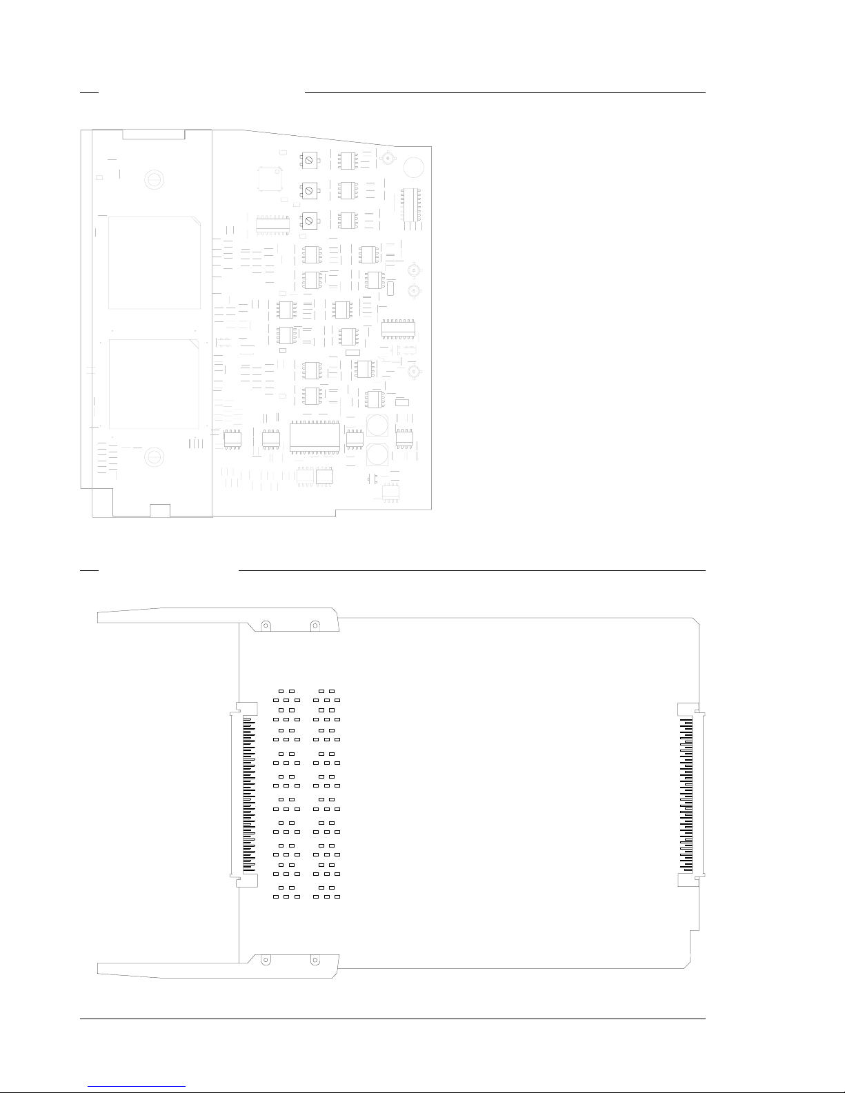
3. Adjust the R, G and B potentiometers on the digital video board to obtain the correct output amplitudes.
Measure at: Adjust with: Required result:
Extender X22
(Video mux.)
MP B50 ZR258 (R) 1400mV
MP B42 ZR458 (G) 1400mV
MP B46 ZR658 (B) 1400mV
6. Switch off power. Return digital video board and video mux. board (Triax adapter) to their positions in the
camera and adapter.
Page 34
4-8 Technical Manual LDK 100 - Camera Head Adjustments
Video Monitoring Adjustment
ZR42
Sync. / Monitoring Board
Page 35
Adjustments Technical Manual LDK 100 - Camera Head 4-9
Set-up
1. Switch off power. Place sync. monitoring board on service extender. Switch on power.
2. Switch on colour bar.
Viewfinder output level
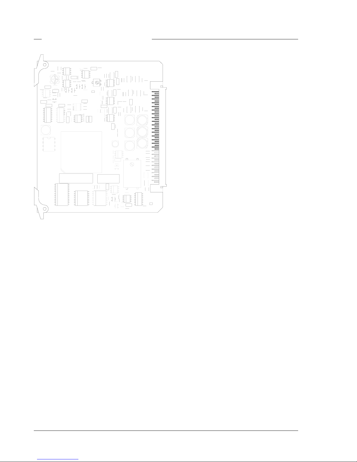
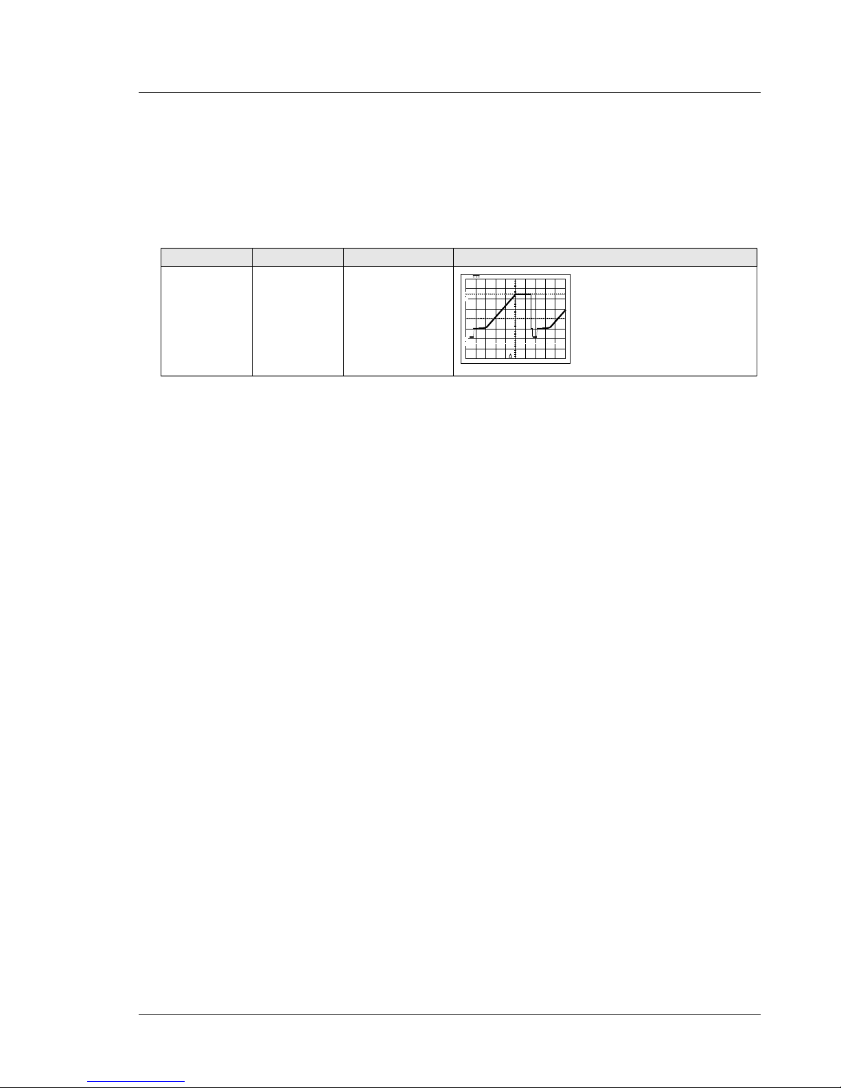
3. Connect oscilloscope terminated with 75 Ohm to the VF output on the back panel.
4. Adjust the potentiometer on the sync. monitoring board to obtain the correct output amplitude VF output signal.
Measure at: Adjust with: Required result: Correct:
VF output ZR42 PAL 700mV
0%
10
90
100
0.2V
10µS
VB+700mV
NTSC 714mV
(100IRE)
5. Switch off power. Return sync. monitoring board to its position in the camera.
Page 36

4-10 Technical Manual LDK 100 - Camera Head Adjustments
Page 37

Diagnostics Technical Manual LDK 100 - Camera Head 5-1
Section 5
Diagnostics
This section contains an explanation of the internal diagnostic system of the camera. The diagnostic
messages and the block diagrams are a useful help when fault finding.
Contents
Diagnostic Messages ......................................... 5-2
Page 38

5-2 Technical Manual LDK 100 - Camera Head Diagnostics
Diagnostic Messages
The internal system of the camera can carry out a
diagnostic test. When the test is started via the menu
system, the status of the various units is displayed in
the diagnostic menu.
If a test fails then a message is displayed to indicate
the module that has not passed the test. At the service
level, additional information is given to indicate which
particular test has failed.
Test Id Test Fails Message, User0-3 Message, Service1-2 %
1. ViPr - SPI Continue Video Proc Fails SPI Error 90
2. ViPr - IIC Continue Video Proc Fails IIC Error 90
3. ICB - IIC Continue InterCon.B Fails IIC Error 90
4. PPG - IIC Continue Pulse Generator Fails IIC Error 90
5. PPG - SPI Continue Pulse Generator Fails SPI Error 90
6. PrPr - IIC Continue PreProcessor Fails IIC Error 90
7. FrDr - IICjudge all iic/spi tests ContinueStop FrontDriver FailsDataboard Fails IIC ErrorIIC/SPI Error 90
8. FrDr - Sensor_Supply Stop Front Driver Fails Sensor Supply
9. FrDr - Shutter Stop Front Driver Fails Shutter not running
10. ViPr - ASIC_AB Stop Video Proc Fails BST ASIC A->B 90
11. ViPr - FreqLock Stop Video Proc Fails FreqLock 70
12. ViPr - ASIC_B_Adapter Stop Video Proc Fails BST ASIC->buffer 70
13. ViPr - RGB_Out Stop Video Proc Fails I/O Error 80
14. ViPr - Sawtooth Stop Video Proc Fails Sawtooth Fails 80
15. ViPr - VF_Y Stop Video Proc Fails VF signal Fails 80
16. SyMo - VF video Stop Sync Monit. Fails VF signal Fails 80
17. PrPr - Clamp Stop PreProcessor Fails Clamp/WhPulse
18. PrPr - Gain0 Stop PreProcessor Fails Output
19. PrPr - Gain1 Stop PreProcessor Fails AGC Fails
20. PrPr - Gain2 Stop PreProcessor Fails AGC Fails
21. PrPr - VSawtooth Stop PreProcessor Fails V-Sawtooth Fails
22. Sensor_Video Stop PPG/Front Fails No Video
23. FSP - IIC Warning Front Switch Fails IIC Error 90
24. LSP - IIC Warning Left Switch Fails IIC Error 90
25. CBRC - IIC Warning Right Cover Fails IIC Error 90
26. SeDa - Calibrations Warning xx Calibrations xx not performed
The table below lists the tests in the order in which they
are performed. It indicates the action that is taken if the
test fails and it lists the messages that are displayed.
An indication of the degree of certainty for each test is
also given.
Page 39

Wiring & Block Diagrams Technical Manual LDK 100 - Camera Head 6-1
Section 6
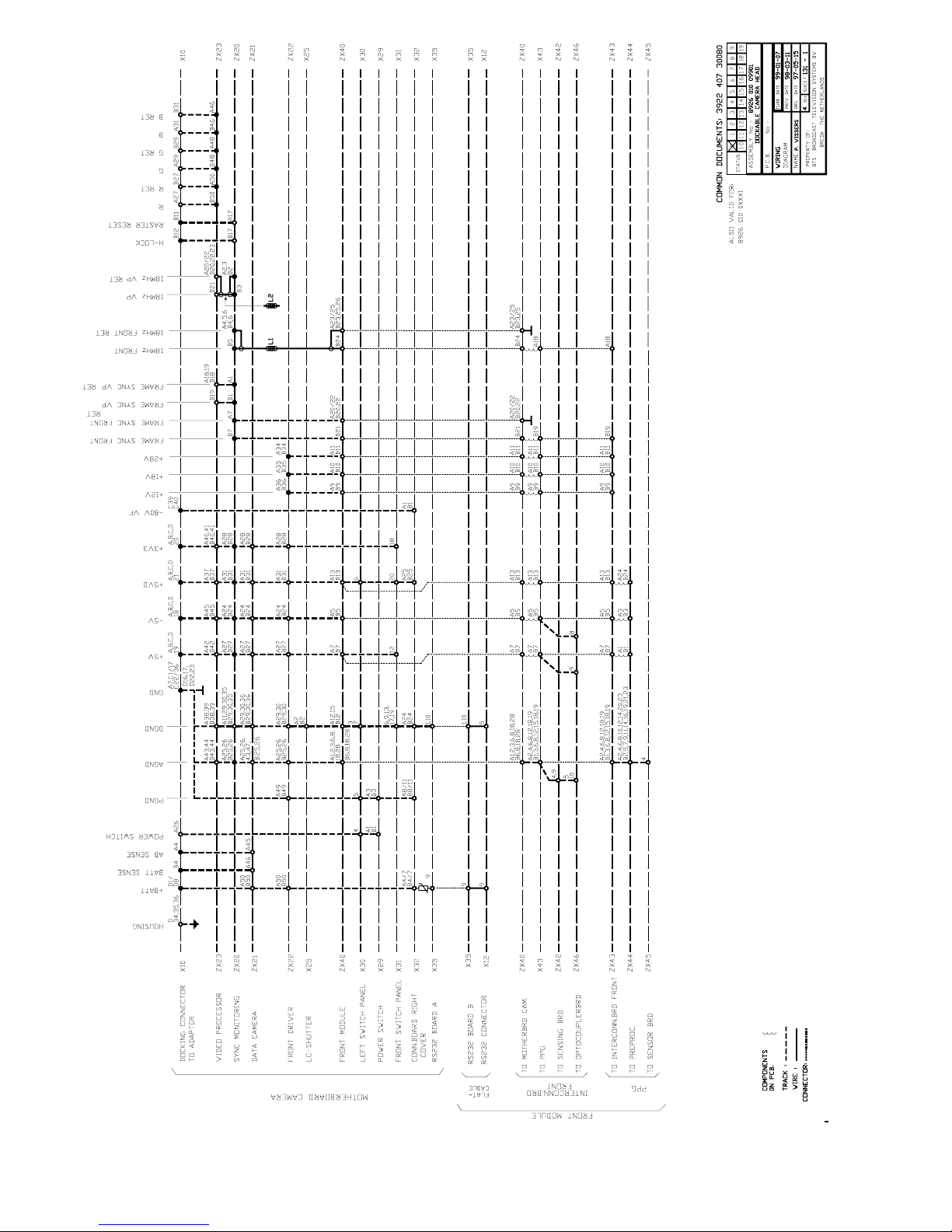
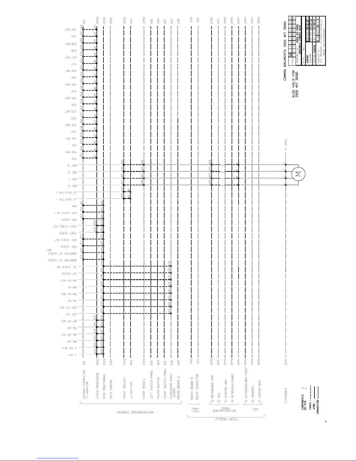
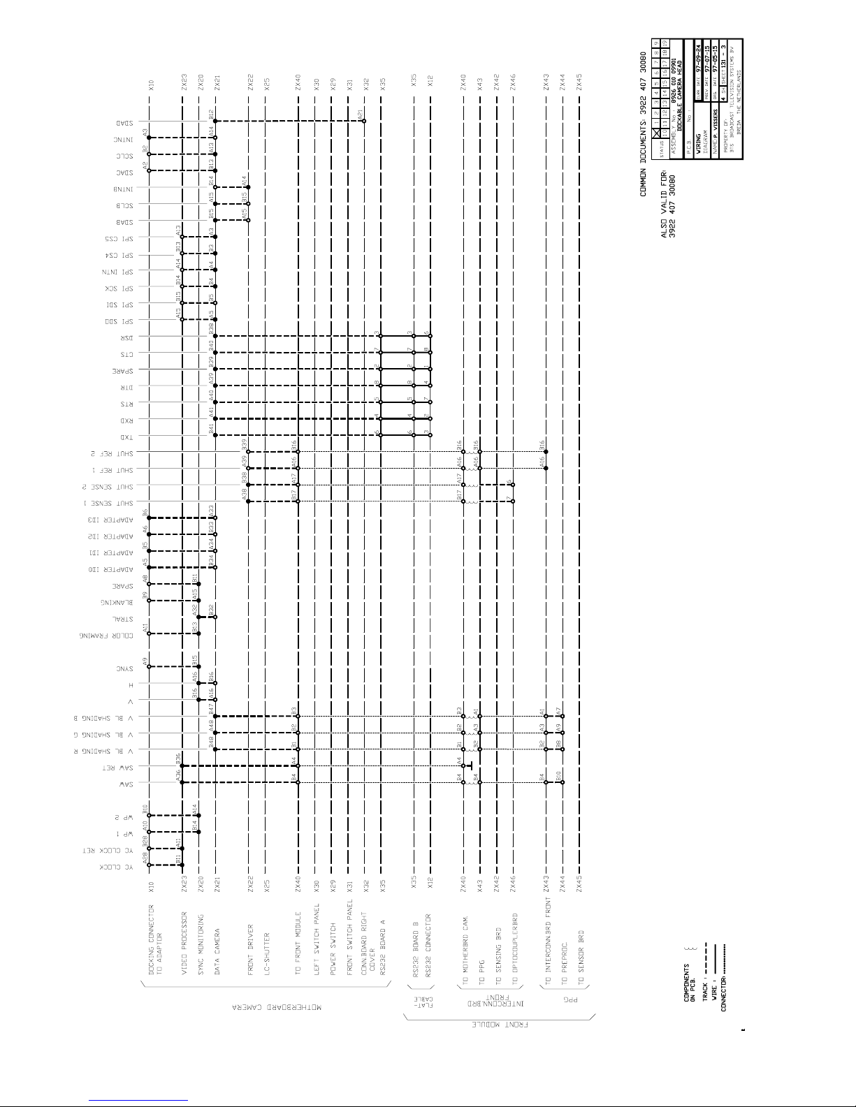
Wiring & Block Diagrams
Contents
Wiring Diagram Dockable Camera Head ............. 6-2 Block Diagram Dockable Camera Head .............. 6-6
Page 40
6-2 Technical Manual LDK 100 - Camera Head Wiring & Block Diagrams
Page 41
Wiring & Block Diagrams Technical Manual LDK 100 - Camera Head 6-3
Page 42
6-4 Technical Manual LDK 100 - Camera Head Wiring & Block Diagrams
Page 43
Wiring & Block Diagrams Technical Manual LDK 100 - Camera Head 6-5
Page 44
6-6 Technical Manual LDK 100 - Camera Head Wiring & Block Diagrams
Page 45
Wiring & Block Diagrams Technical Manual LDK 100 - Camera Head 6-7
Page 46
6-8 Technical Manual LDK 100 - Camera Head Wiring & Block Diagrams
Page 47
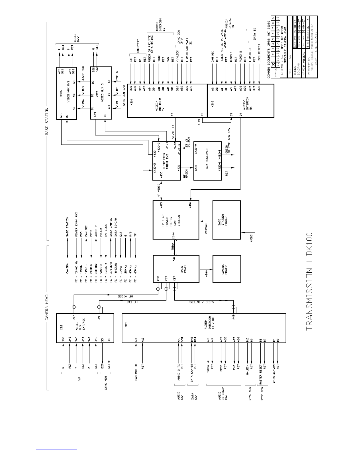
Wiring & Block Diagrams Technical Manual LDK 100 - Camera Head 6-9
Page 48
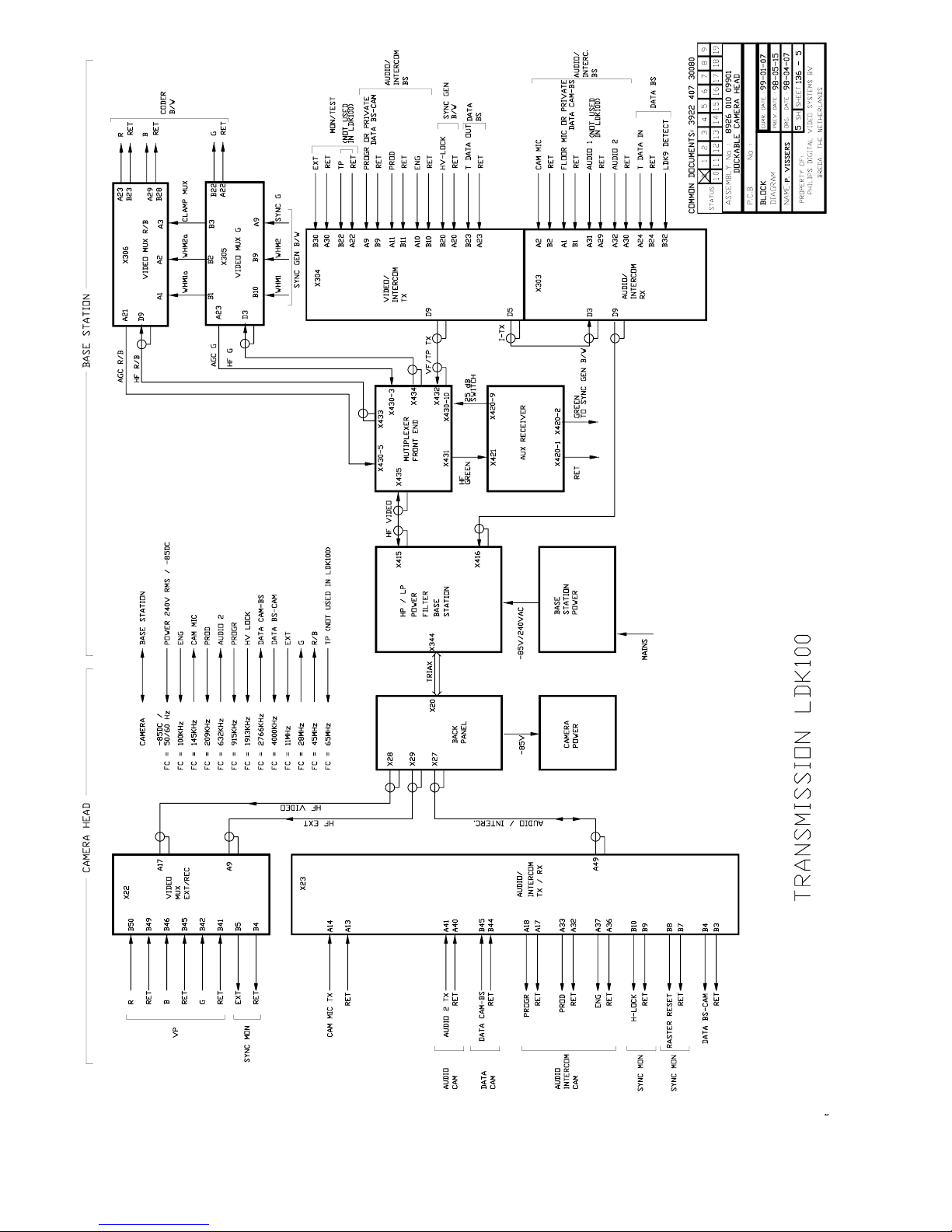
6-10 Technical Manual LDK 100 - Camera Head Wiring & Block Diagrams
Page 49

Mechanical Exploded Views Technical Manual LDK 100 - Camera Head 7-1
Section 7
Mechanical Exploded Views
Contents
Camera head Basic............................................ 7-2
Cover left assy................................................... 7-3
Cover right assy ................................................. 7-4
Hand grip assy ................................................... 7-5
Hand grip rubber assy ........................................ 7-6
Shoulder pad assy ............................................. 7-7
Front module PAL .............................................. 7-8
Front module PAL IT 800PX .............................. 7-9
Front module PAL ITW..................................... 7-10
Optical module PAL switchable ........................ 7-11
Optical module PAL IT 800PX ......................... 7-12
Optical module PAL ITW.................................. 7-13
Dockable camera head..................................... 7-14
Page 50
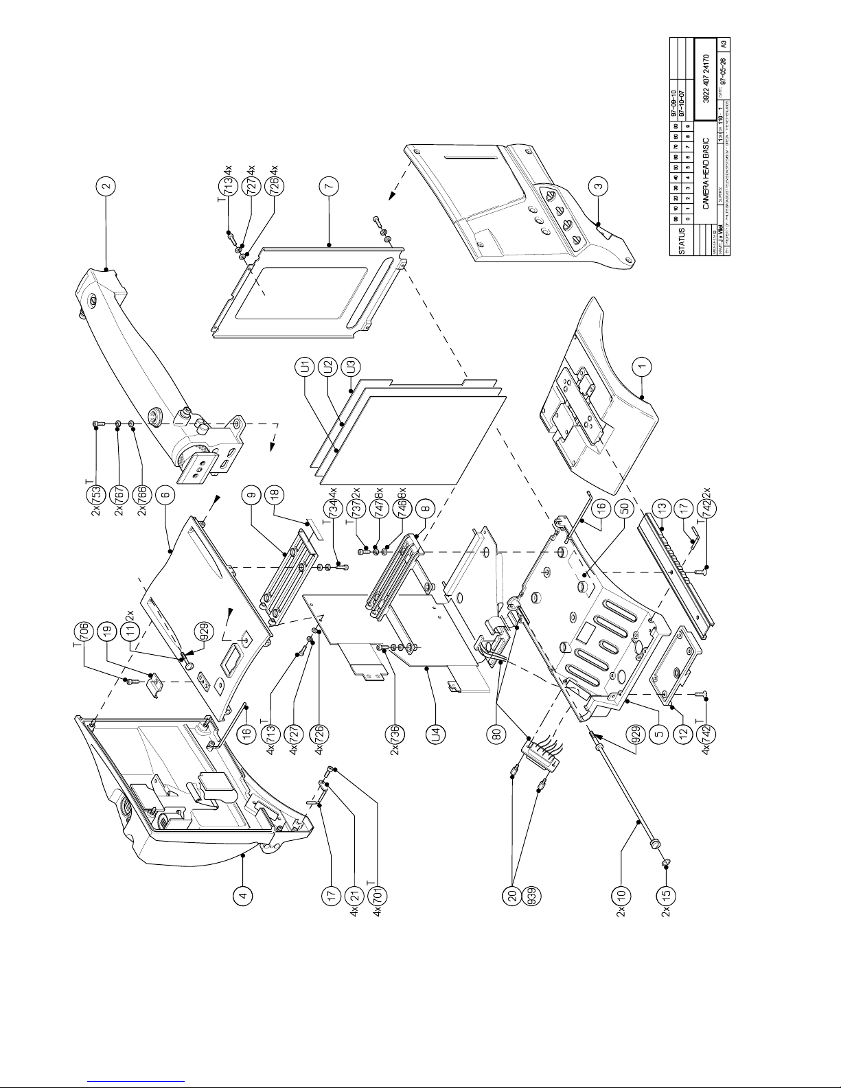
7-2 Technical Manual LDK 100 - Camera Head Mechanical Exploded Views
Page 51
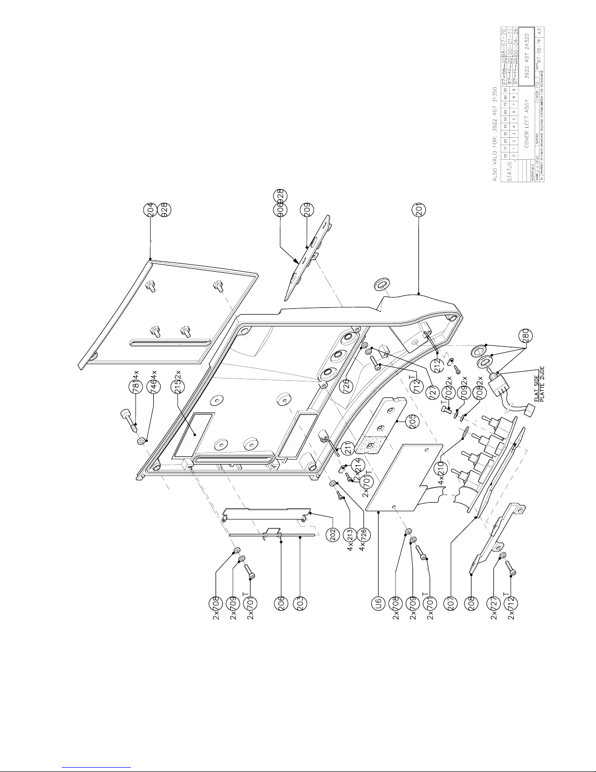
Mechanical Exploded Views Technical Manual LDK 100 - Camera Head 7-3
Page 52
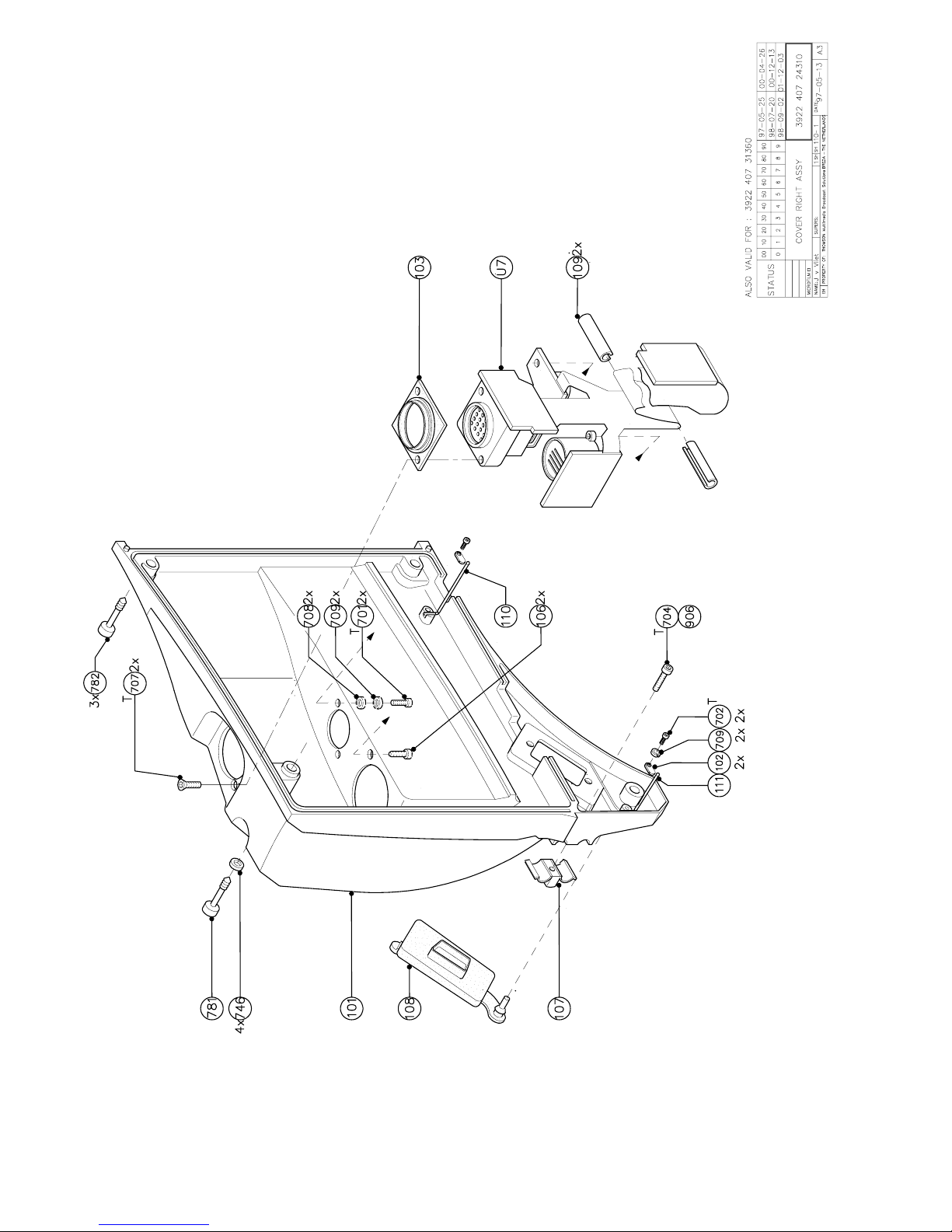
7-4 Technical Manual LDK 100 - Camera Head Mechanical Exploded Views
Page 53
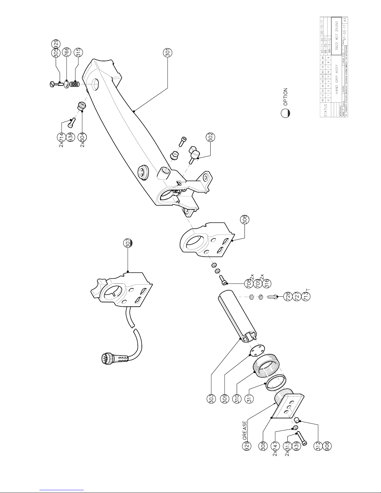
Mechanical Exploded Views Technical Manual LDK 100 - Camera Head 7-5
Page 54
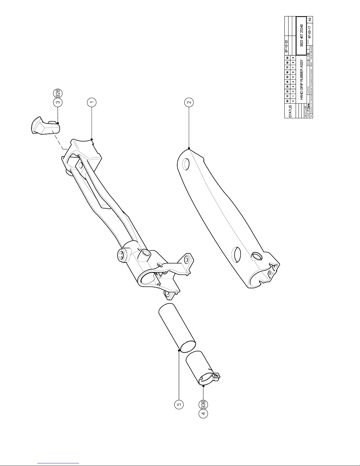
7-6 Technical Manual LDK 100 - Camera Head Mechanical Exploded Views
Page 55
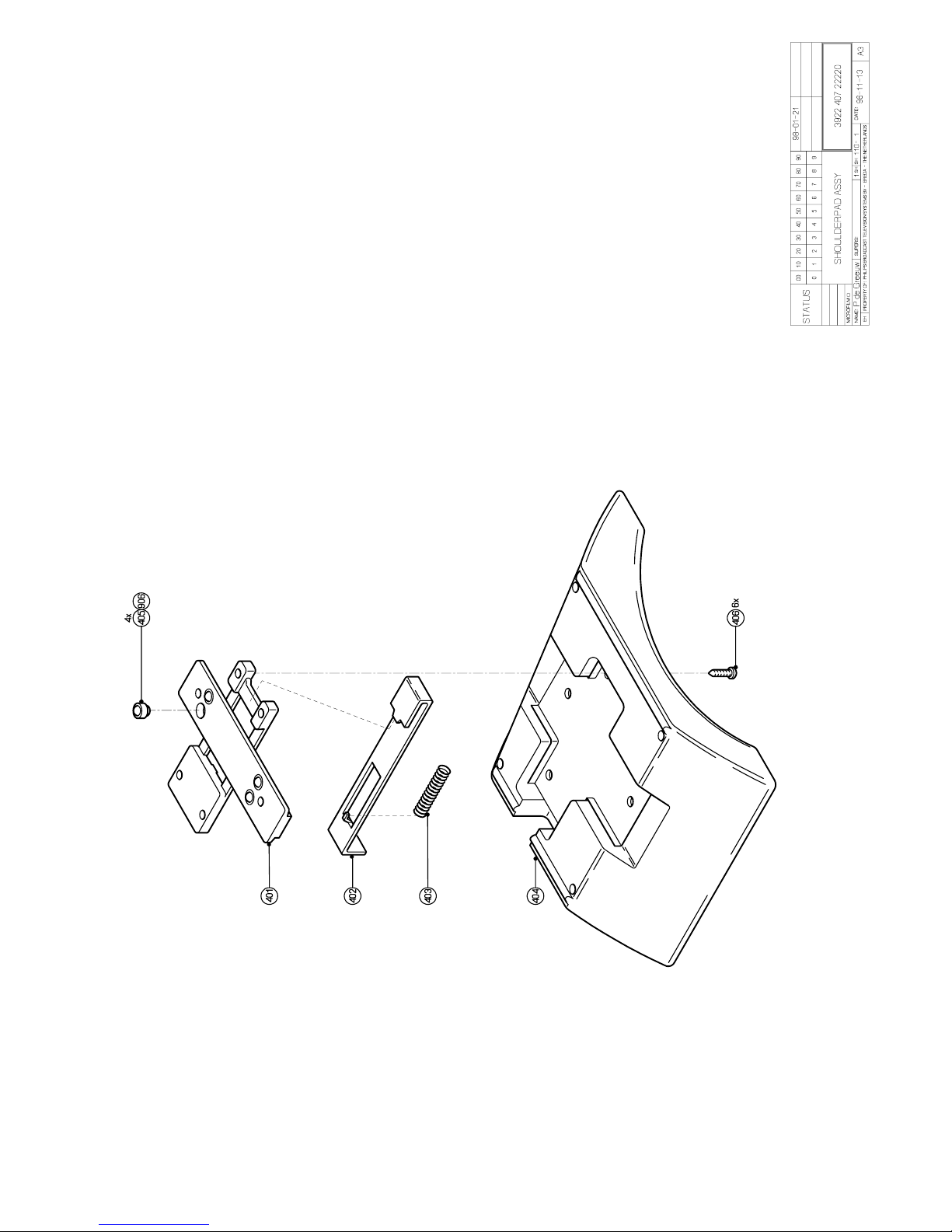
Mechanical Exploded Views Technical Manual LDK 100 - Camera Head 7-7
Page 56
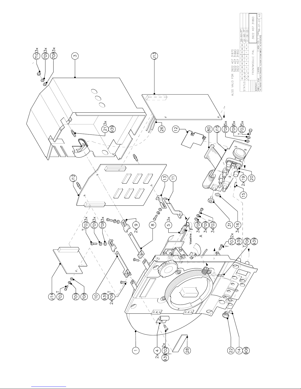
7-8 Technical Manual LDK 100 - Camera Head Mechanical Exploded Views
Page 57
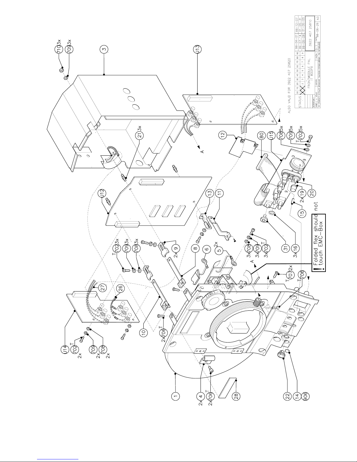
Mechanical Exploded Views Technical Manual LDK 100 - Camera Head 7-9
Page 58
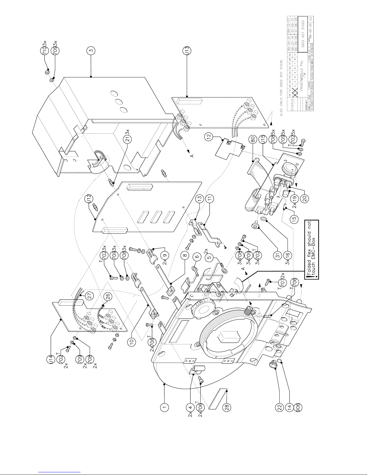
7-10 Technical Manual LDK 100 - Camera Head Mechanical Exploded Views
Page 59
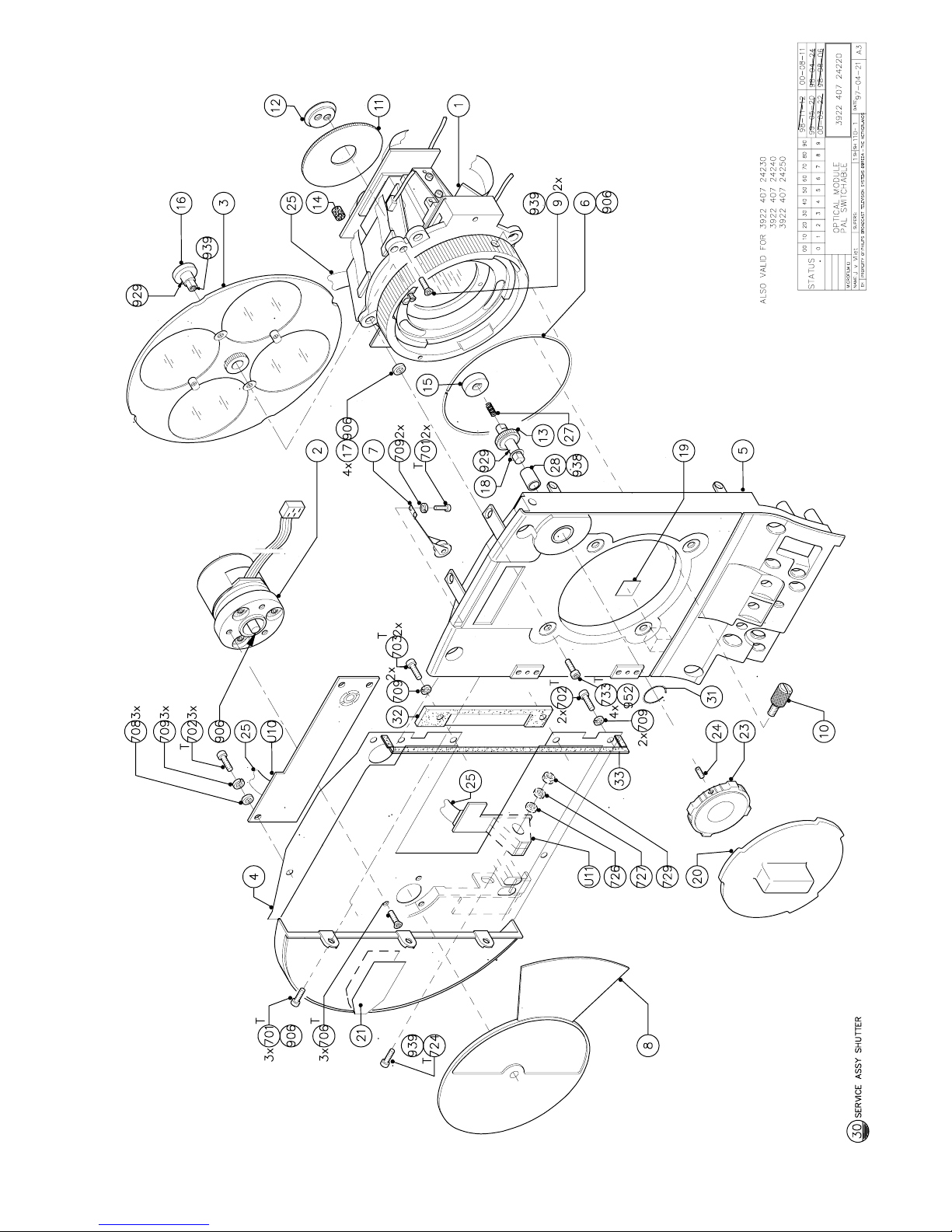
Mechanical Exploded Views Technical Manual LDK 100 - Camera Head 7-11
Page 60
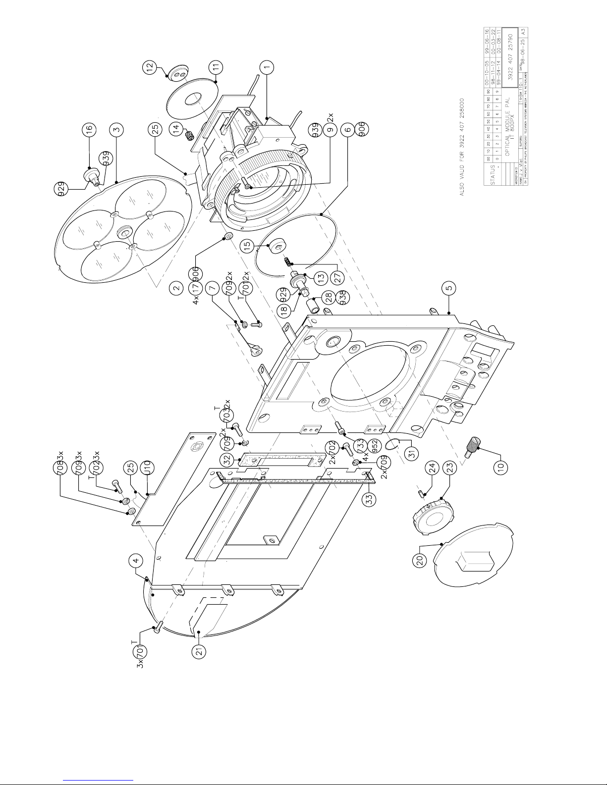
7-12 Technical Manual LDK 100 - Camera Head Mechanical Exploded Views
Page 61
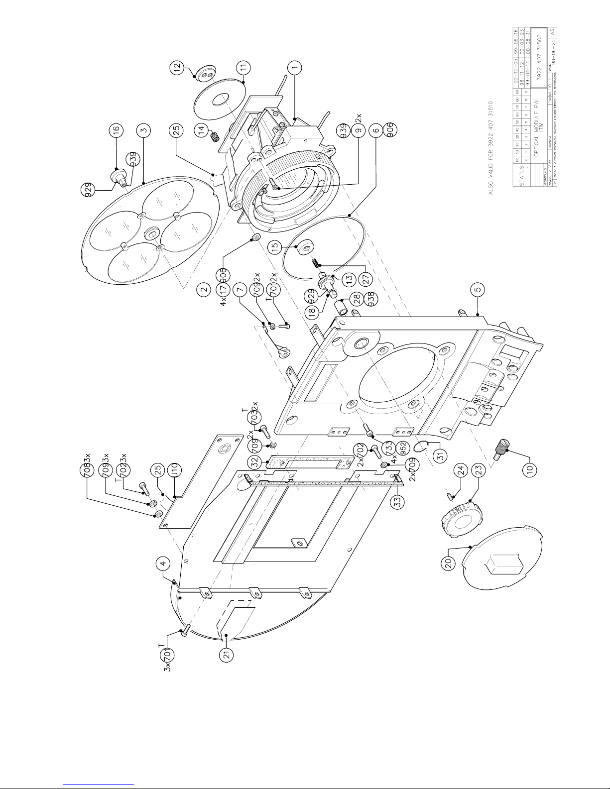
Mechanical Exploded Views Technical Manual LDK 100 - Camera Head 7-13
Page 62
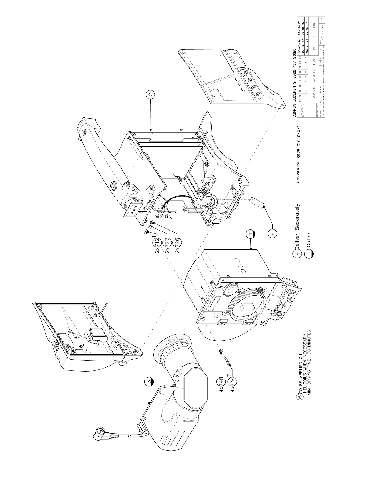
7-14 Technical Manual LDK 100 - Camera Head Mechanical Exploded Views
Page 63

Parts Lists Technical Manual LDK 100 - Camera Head 8-1
Section 8
Parts Lists
 Loading...