

Page 1
SERVICE MANUAL
DOCUMENTATION TECHNIQUE
TECHNISCHE DOKUMENTATION
DOCUMENTAZIONE TECNICA
DOCUMENTACION TECNICA
No copying, translation, modification on other use authorized. All rights reserved worldwide. • Tous droits de reproduction, de traduction, d'adaptation et d'exécution réservés pour tous les pays. • Sämtliche Urheberrechte an diesen Texten und Zeichnungen stehen uns zu. Nachdrucke,
Vervielfältigungen - auch auszugsweise - nur mit unserer vorherigen Zustimmung zulässig. Alle Rechte vorbehalten. • I diritti di riproduzione, di traduzione, e esecuzione sono riservati per tutti i paesi. • Derechos de reproduccion, de traduccion, de adaptacion y de ejecucion reservados para todos los paises.
WARNING : Before servicing this chassis please read the safety recommendations.
ATTENTION : Avant toute intervention sur ce châssis, lire les recommandations de sécurité.
ACHTUNG : Vor jedem Eingriff auf diesem Chassis, die Sicherheitsvorschriften lesen.
ATTENZIONE : Prima di intervenire sullo chassis, leggere le norme di sicurezza.
IMPORTANTE : Antes de cualquier intervención, leer las recomendaciones de seguridad.
Code :357 510 10 - 0304 / 6M -LCDB03B Print.
LCD03B
TV
Page 2
MAIN
FRANÇAIS ESPAÑOLDEUTSCHENGLISH ITALIANO
1
2
3
4
5
6
7
8
9
10
11
12
13
14
15
16
17
18
19
20
21
NC
21
17
19
15
13
20
18
16
14
12
11
9
10
8
7
5
3
1
6
4
2
NC
AUDIO "R"
AUDIO "R"
AUDIO "L"
NOTE :
... etc. identifies each
pcb module.
AUDIO "D"
AUDIO "D"
AUDIO "G"
AUDIO
"BLEU"
AUDIO "G" MONO
"BLEU"
COMMUT. LENTE
"VERT"
"VERT"
"ROUGE"
COMMUT. RAPIDE
COMMUT. RAPIDE
VIDEO
VIDEO SYNCHRO
BLINDAGE PRISE
AUDIO "R"
AUDIO "R"
AUDIO "L"
AUDIO
"BLAU"
AUDIO "L" MONO
"BLAU"
AV
UMSCHALTUNG
"GRÜN"
"GRÜN"
"ROT"
AUSTASTUNG
AUSTASTUNG
VIDEO
VIDEO ODER
SYNCHRO
ABSCHIRMUNG
DES STECKERS
AUDIO "D"
AUDIO "D"
AUDIO "I"
AUDIO
"AZUL"
AUDIO "I" MONO
AZUL
"CONMUTACION
LENTA"
"VERDE"
"VERDE"
"ROJA"
"CONMUTACION
RAPIDA"
"CONMUTACION
RAPIDA"
VIDEO
VIDEO O SINCRO
BLINDAJE
DEL ENCHUFE
AUDIO "D"
AUDIO "D"
AUDIO "S"
AUDIO
"BLU"
AUDIO "S" MONO
BLU
"COMMUTAZIONE
LENTA"
"VERDE"
"VERDE"
"ROSSO"
"COMMUTAZIONE
RAPIDA"
"COMMUTAZIONE
RAPIDA"
VIDEO
VIDEO O SINCRO
INVOLUCRO METAL-
LICO DELLA PRESA
AUDIO "L" MONO
"BLUE"
"GREEN"
AV LINK AV LINK AV LINK AV LINK AV LINK
"GREEN"
"RED"
"ROUGE" "ROT" "ROJA""ROSSO""RED"
SLOW SWITCH
FAST SWITCH
VIDEO
VIDEO VIDEO VIDEOVIDEOVIDEO
PLUG SCREEN
BOX
VIDEO OR "SYNC"
FAST SWITCH
AUDIO
"BLUE"
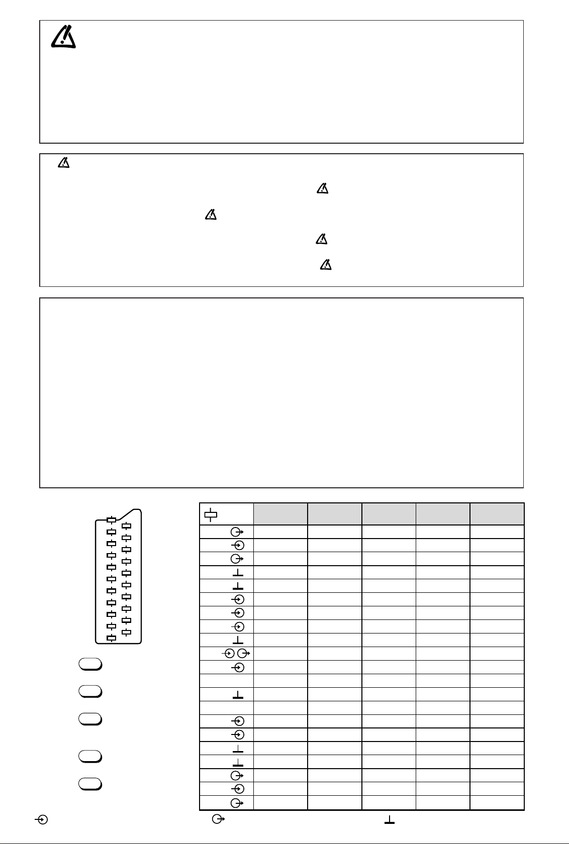
: OUTPUT - SORTIE - AUSGANG - USCITA - SALIDA •
: EARTH - MASSE - MASSE - MASSA - MASA
MAIN
NOTE :
... etc. repères des
platines constituant l'appareil.
MAIN
NOTA :
... etc. marcas de las
placas que constituyen el
aparato.
MAIN
NOTA :
... ecc. sigla delle
piastre dell' apparecchio.
MAIN
HINWEIS :
... usw. Kennzeichnung
der Platinen, aus denen das
Gerät zusammengesetzt ist.
: INPUT - ENTRÉE - EINGANG - ENTRATA - ENTRADA •
Do not disconnect modules when they are energized!
Repairs on power supply section are to be carried out only with isolating transformer.
Ne pas retirer les modules lorsqu' ils sont sous tension. N'effectuer les travaux de maintenance sur la partie reliée
au secteur (Switch Mode) qu'au travers d'un transformateur d'isolement.
Module nicht bei eingeschaltetem Gerät entfernen!
Servicearbeiten am Netzteil nur unter Verwendung eines Regeltrenntrafos durchführen.
Non scollegare le piastre quando sono alimentate!
Per le riparazioni sulla sezione alimentatore, utilizzare un trasformatore isolatore.
No desconectar los módulos cuando están activados. Las reparaciones en la sección de alimentación de energía
deben ser ejecutadas solamente con un transformador de separación.
Indicates critical safety components, and identical components should be used for replacement. Only then can the
operational safety be garanteed.
Le remplacement des éléments de sécurité (repérés avec le symbole ) par des composants non homologués selon la
Norme CEI 65 entraine la non-conformité de l'appareil. Dans ce cas, la responsabilité du fabricant n'est plus engagée.
Wenn Sicherheitsteile (mit dem Symbol gekennzeichnet) nicht durch Original - Ersatzteile ersetzt werden, erlischt die
Haftung des Herstellers.
La sostituzione dei componenti di sicurezza (evidenziati con il segno ) con componenti non omologati secondo la
norma CEI 65 comporta la non conformitá dell'apparecchio. In tal caso è "esclusa la responsabilità " del costruttore.
La sustitución de elementos de seguridad (marcados con el simbolo ) por componentes no homologados segun la
norma CEI 65, provoca la no conformidad del aparato. En ese caso, el fabricante cesa de ser responsable.
MEASUREMENT CONDITIONS - CONDITIONS DE MESURES - MESSBEDINGUNGEN
CONDIZIONI DI MISURA - CONDICIONES DE MEDIDAS
RECEIVER :
On UHF,input level : 1 mV, bar test pattern :
- PAL, I standard, 100% white.
Via the scart socket, input level : 1 Vpp, bar test pattern :
Colour, contrast and brightness at mid-position, sound at minimum.
Programme selected : PR 01.
DC voltages measured between the point and earth using a digital
voltmeter.
RICEVITORE :
In UHF, livello d'entrata 1 mV, monoscopio barre :
- PAL, norma G. bianco 100%.
Via SCART, livello d'entrata 1 Vpp, monoscopio barre :
Colore, Contrasto, Luminositá media, Suono minimo.
Programma selezionato PR 01.
Tensioni continue rilevate rispetto alla massa con un voltmetro digitale.
RECEPTEUR :
En UHF, niveau d'entrée 1 mV mire de barres
- SECAM, Norm L, Blanc 100%.
Par la prise Péritélévision, niveau d'entrée 1 Vcc, mire de barres .
Couleur, contraste, lumière à mi-course, son minimum.
Programme affecté PR 01.
Tensions continues relevées par rapport à la masse avec un
voltmètre numérique.
RECEPTOR :
En UHF, nivel de entrada 1 mV, mira de barras :
- PAL, norma G, blanco 100%.
Por la toma Peritelevision, nivel de entrada 1 Vpp mira de barra.
Color, Contraste, luz a mitad de carrera, Sonido minimo.
Programa afectado PR 01.
Tensiones continuas marcadas en relacion a la masa con un voltimetro digital.
EMPFÄNGER :
Bei UHF Eingangspegel 1 mV, Farbbalken :
- PAL, Norm G, Weiss 100%.
Über die Scartbuchse : Eingangspegel 1 Vss, Farbbalken :
Farbe, Kontrast, Helligkeit in der Mitte des Bereichs, Ton auf Minimum.
Zugeordnetes Programm PR 01.
Gleichspannungen mit einem digitalen Voltmeter zur Masse gemessen.
Page 3
LCD03B
First issue 04 / 04 3
Reference Information Desassembly. Service FCB KDB Inverter DC/DC Audio Earphone Main Video
- Mode - - -- Board Board
15LCDM03B
3 6to7 10to15 “ 16to18 23to24 19to20 25 26 27to41 42to58
20LCDM03B 3 6to7 10to15 “ 16to18 23to24 21to22 25 26 27to41 42to58
20LCDB03B 3 8to9 10to15 “ 16to18 - 21to22 25 26 27to41 42to58
INFORMATION - INFORMATIONS - INFORMATIONEN
INFORMAZIONE - INFORMACIONES
Chassis group table
1 - The electronic chassis configuration (modules) and schematic diagram page numbers.
2 - The chassis configuration.
Le tableau ci-dessous regroupe :
1 - L’environnement électronique de chaque chassis (modules) et le numéro de page où il est décrit.
2 - La désignation des chassis
Die nachstehendeTabelle umfaßt:
1 - Die elektronischen Baugruppen (Module) der Chassis varianten und die Seiten auf der sie beschrieben werden
2 - Die Chassisbezeichnung
La tabella qui di seguito contiene:
1 - l’ambiente elettronico di ogni telaio (moduli) e il numero di pagina nella quale è descritto.
2 - La descrizione dei telai
El cuadro siguiente agrupa:
1 - El entorno electrónico de cada chasis (módulos) y el número de página donde está descrito.
2 - La designación de los chasis
EN
FR
DE
IT
ES
Chassis LCD03B
Page 4
LCD03B
First issue 10 / 03
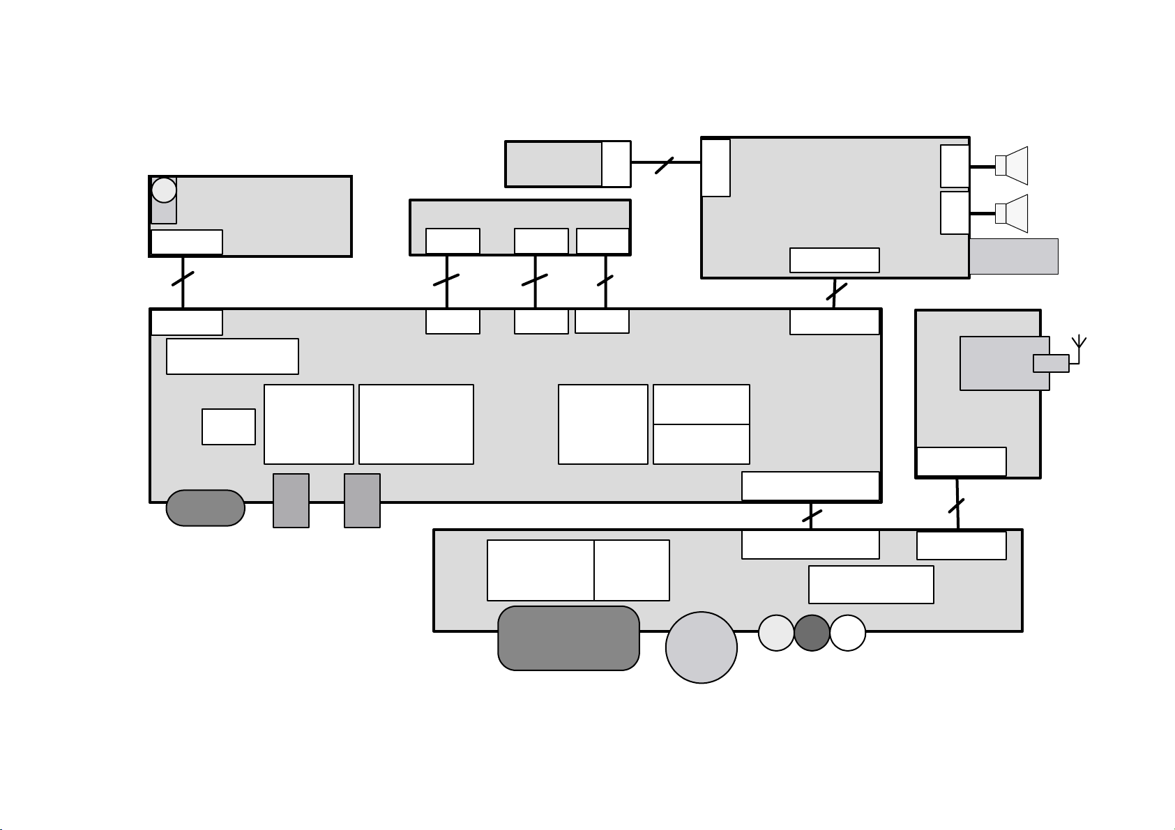
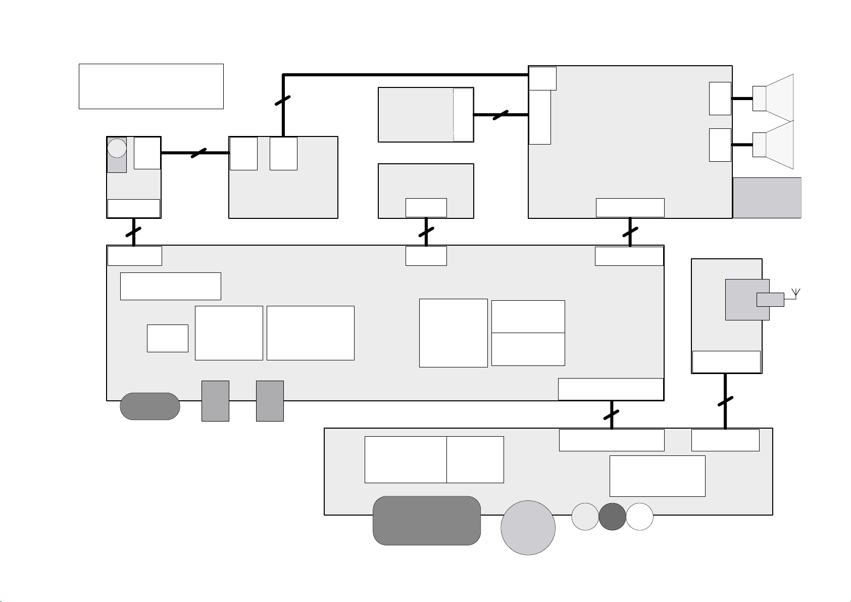
BLOCK DIAGRAM - SCHEMA SYNOPTIQUE - BLOCKSCHALTBILD - SCHEMA A BLOCCHI - ESQUEMA DE BLOQUES
15" ,20"
System Block Diagram (EU version)
Control
12 pin
Board
50 pin*
Inverter
LCD Panel
40 pin**
8
pin
30 pin**
pin
8
PFC/DC+DC/Audio Board
20 pin
2
pin
2
pin
Power
Connector
12 pin
Keypad/IR Interface
DDC
D-Sub
AD
AD9883
Audio Input
Audio Processor
TDA7440D
Audio Line Out
50 pin*
20" model only* 15" model only**
40 pin**
30 pin**
Scaller
PW113
Main Board
De-Interlace
Chipset
PW1230
SCART
VPC3230D
Video
Decoder
Flash
AT49BV8192A
EEPROM
Video Board
S-Video
20 pin
60 pin golden finger
60 pin
Composite
Video
L/R Audio
Tuner
Tuner Module
14 pin
14 pin
Teltext
SDA555XFL
Input
Page 5
LCD03B
First issue 10 / 03
BLOCK DIAGRAM - SCHEMA SYNOPTIQUE - BLOCKSCHALTBILD - SCHEMA A BLOCCHI - ESQUEMA DE BLOQUES
20" BI
20"BiSonic System Bolck
Diagram(EU version)
10
pin
Board
12 pin
12 pin
Keypad/IR Interface
DDC
10
pin
EarPhone Jack
AD
AD9883
5
pin
Keypad Board
Audio Processor
MSP3412G
LCD PanelIR
Main Board
Inverter
50 pin
50 pin
Scaller
PW113
8
pin
5
pin
8
pin
Flash
AT49BV8192A
EEPROM
PFC/DC+DC/Audio Board
20 pin
20 pin
2
pin
2
pin
Power
Connector
Tuner
Tuner Module
14 pin
D-Sub
Audio Input
Audio Line Out
De-Interlace
Chipset
PW1230
SCART
Video
Decoder
VPC3230D
Video Board
S-Video
80 pin golden finger
80 pin
Composit e
Video
L/R Audio
14 pin
Teltext
SDA555XFL
Input
Page 6

Disassembly
process
15LCDM03B
Page N°1
Page 7
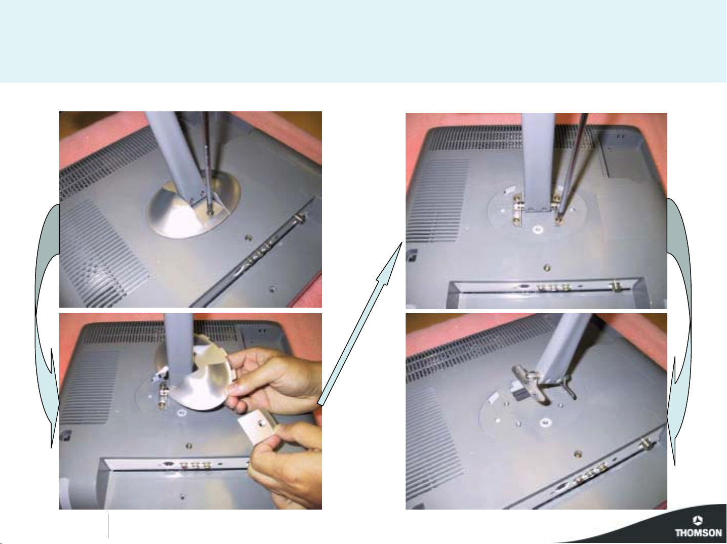
15 " LCD TV
Revision 1.0
Page N°2
Page 8
15 " LCD TV
Revision 1.0
Page N°3
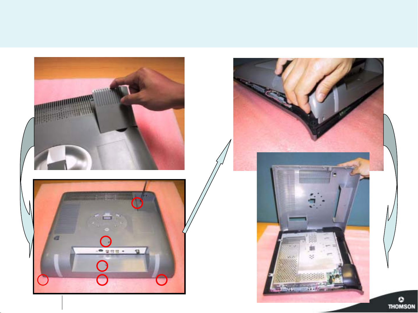
Page 9
15 " LCD TV
Revision 1.0
Page N°4
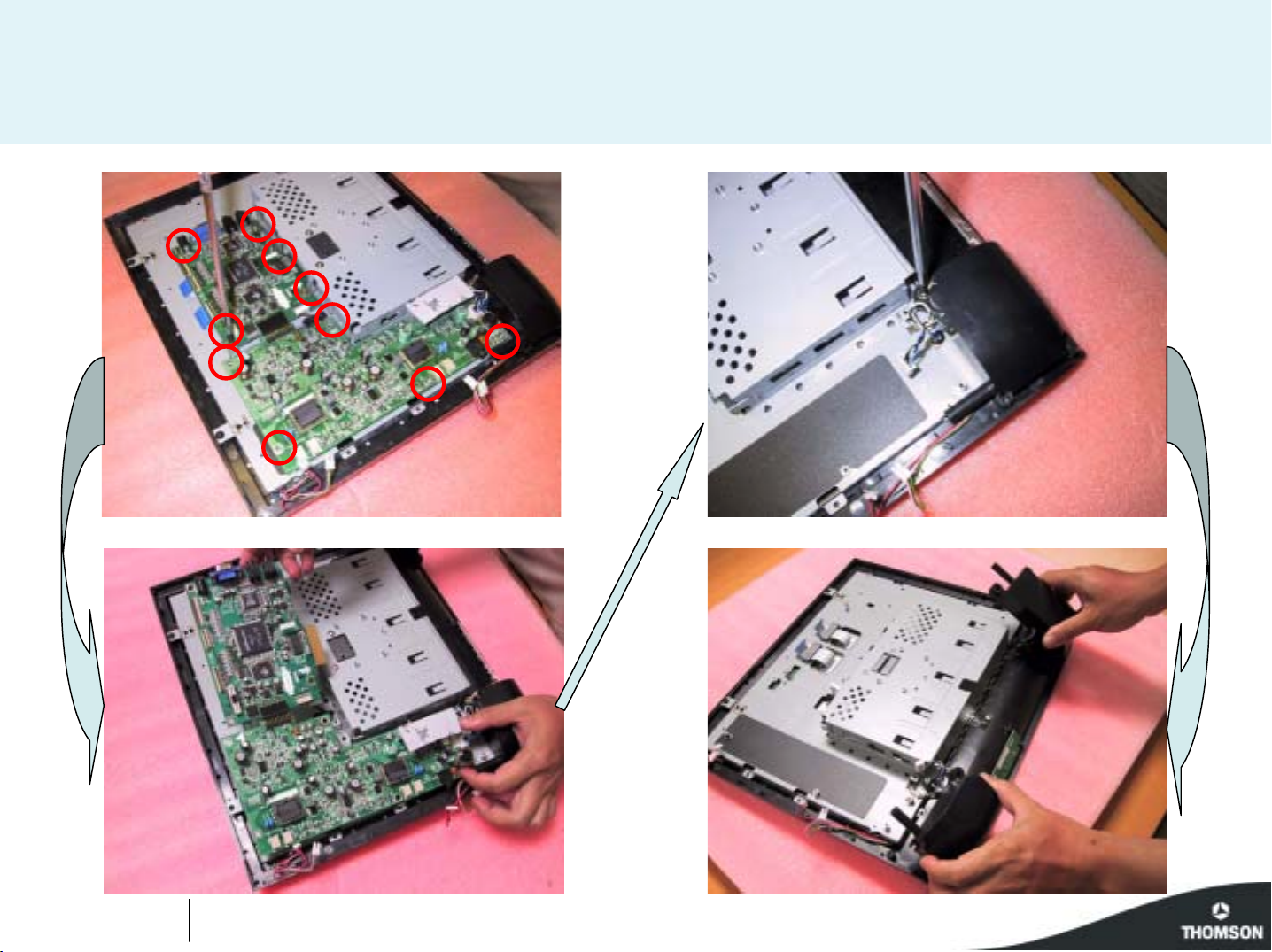
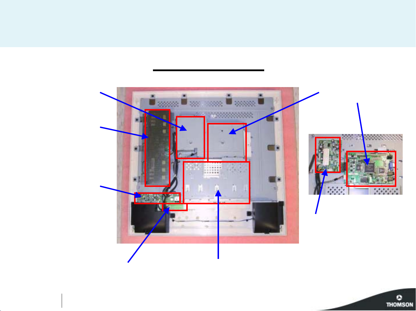
Page 10
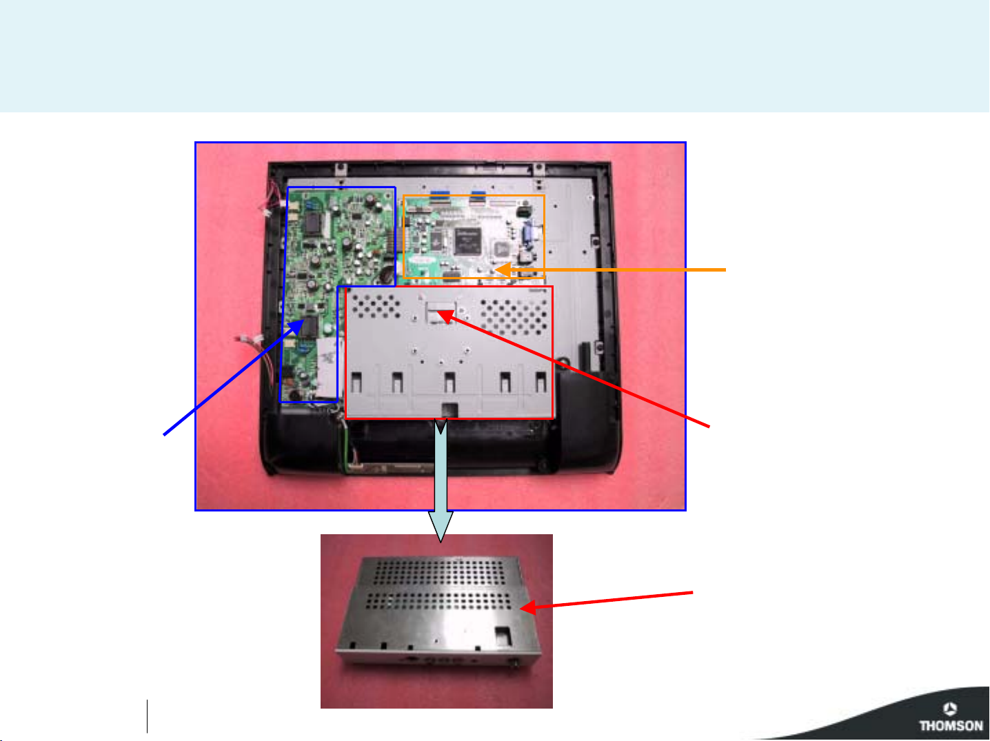
15 " LCD TV
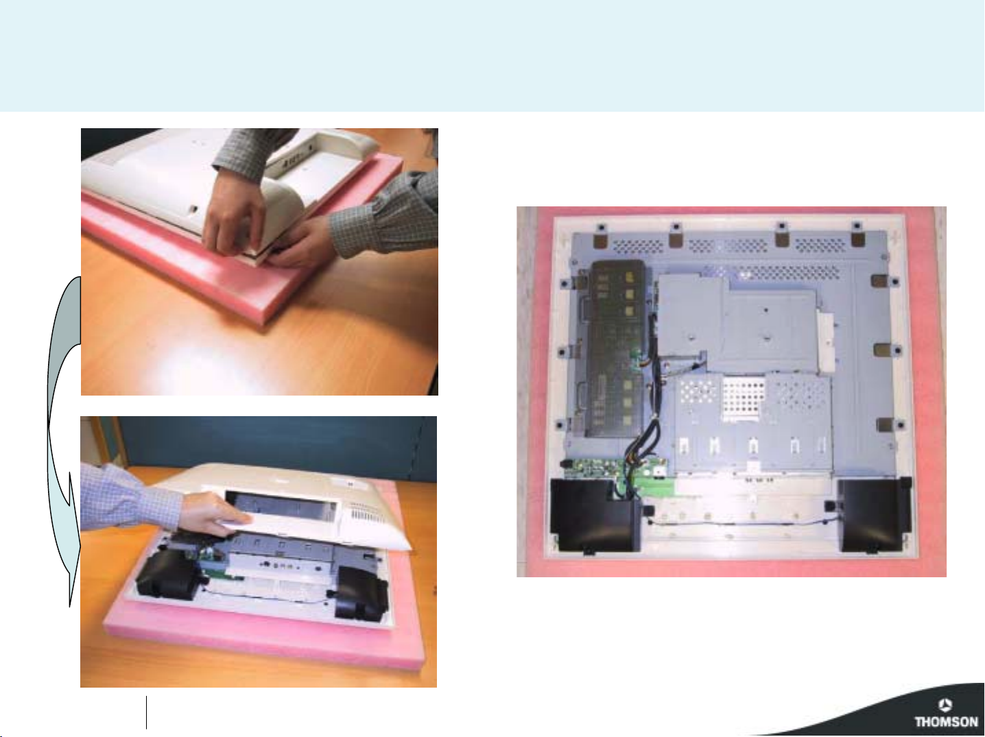
PC board
Slider to extract
Power board
Revision 1.0
Page N°5
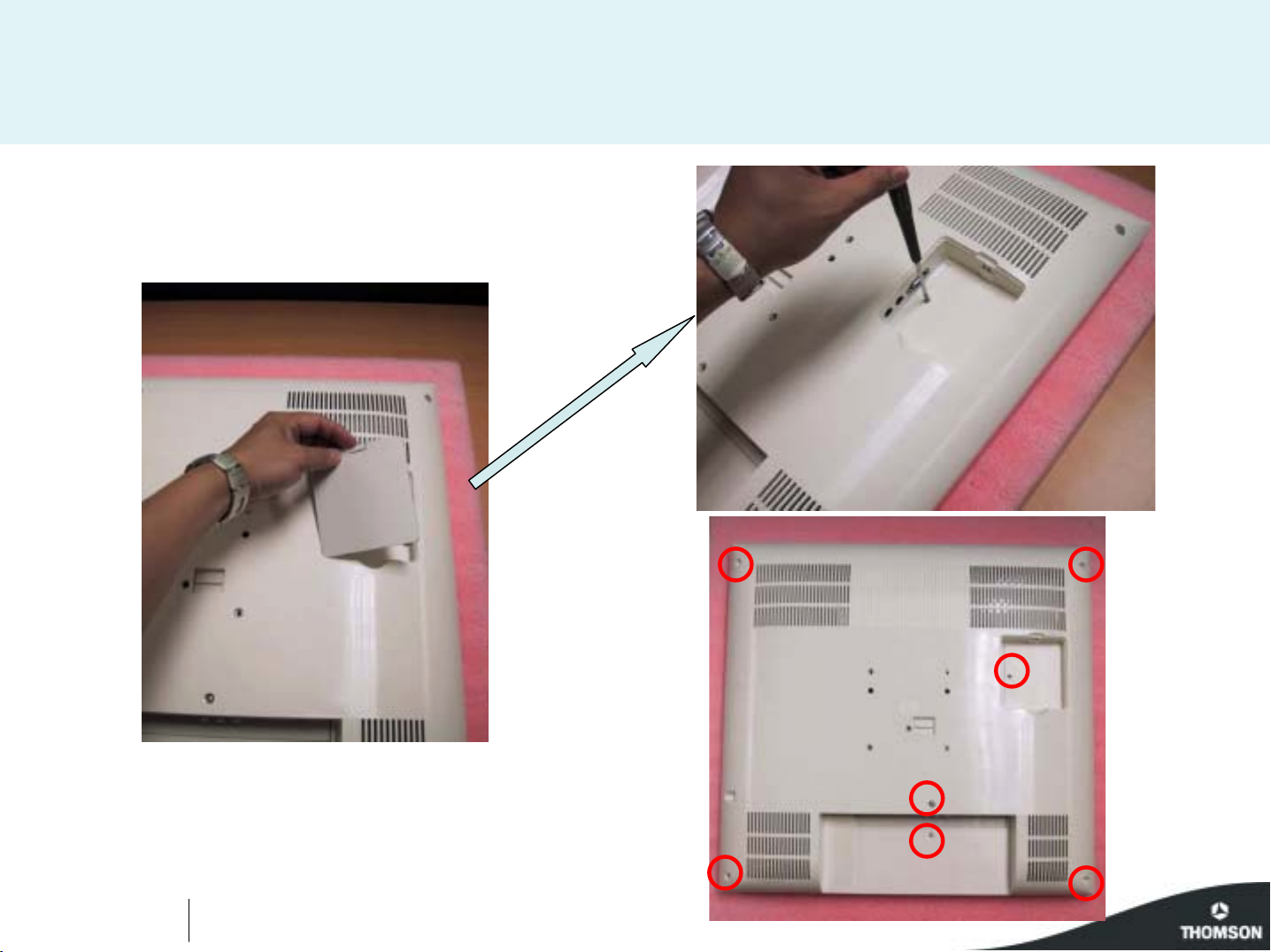
The AV module
AV module :
video and tuner boards
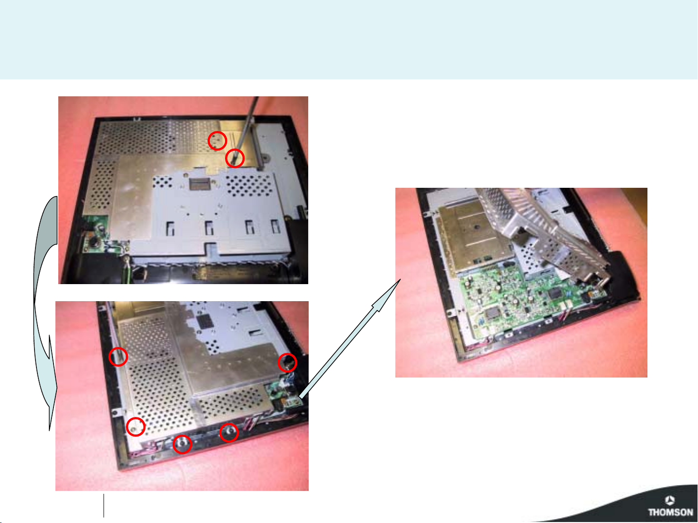
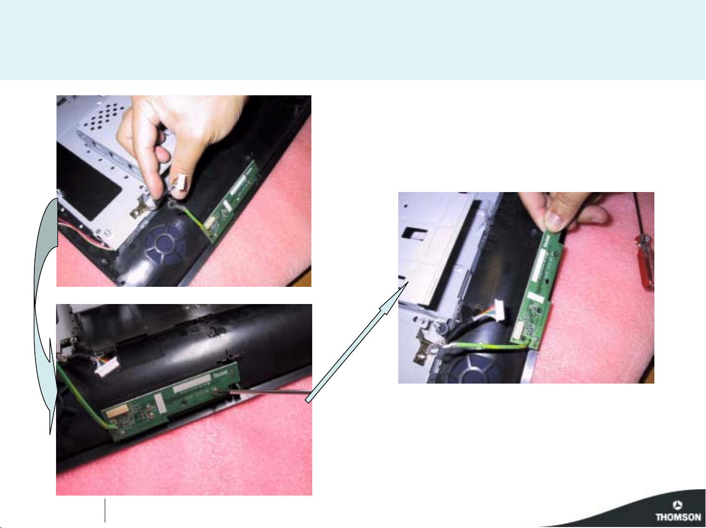
Page 11
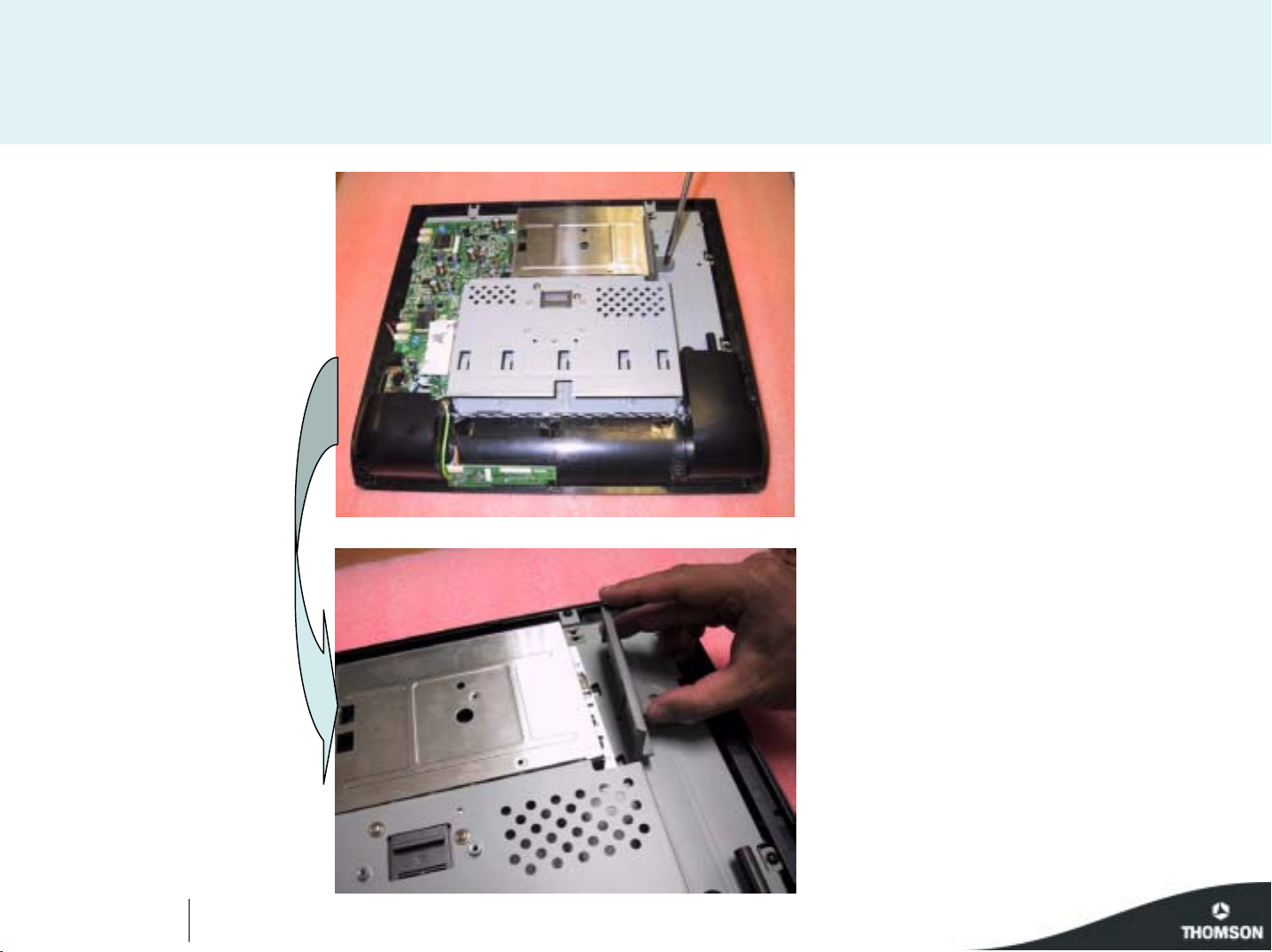
15 " LCD TV
Revision 1.0
Page N°6
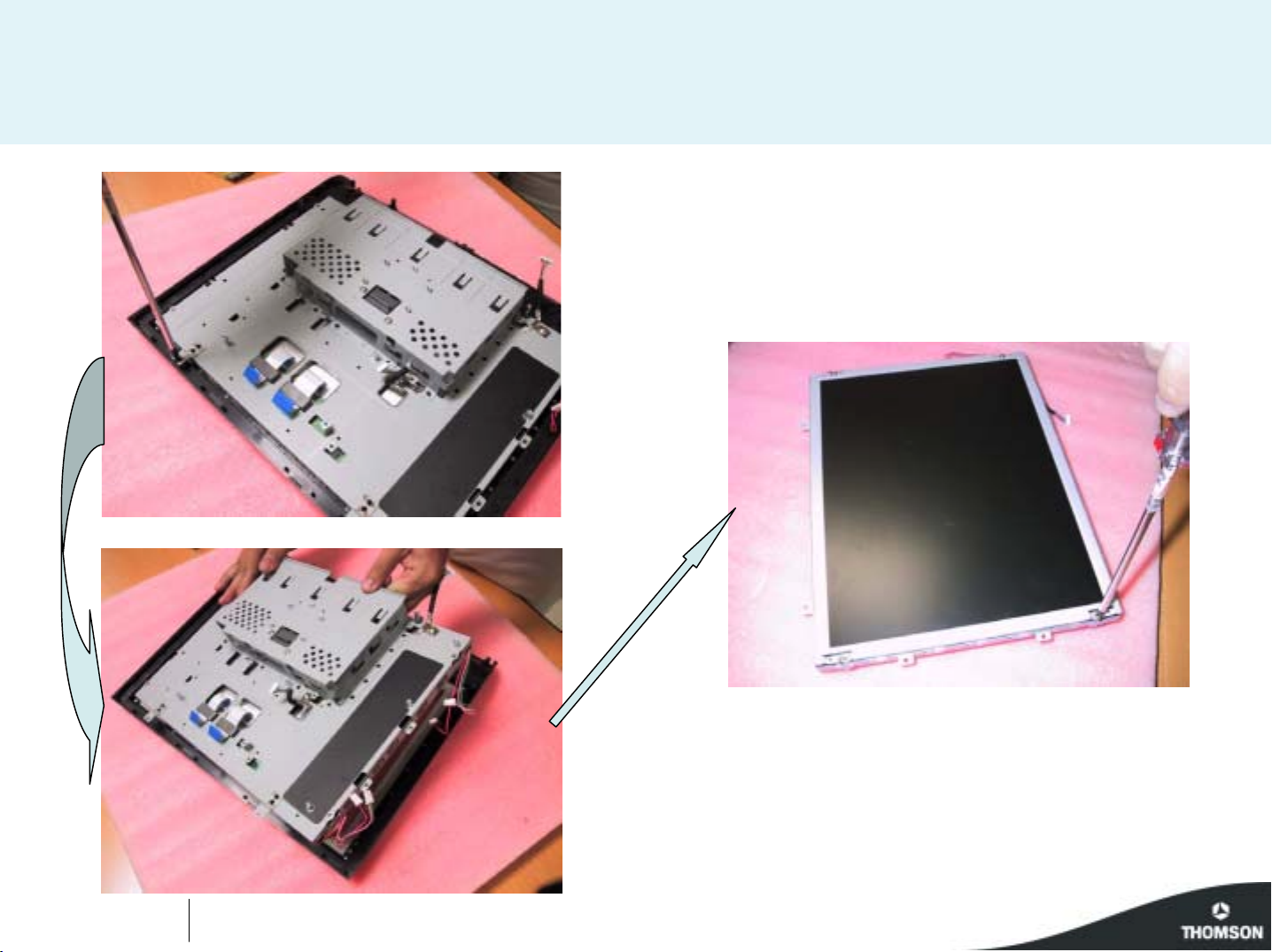
Page 12
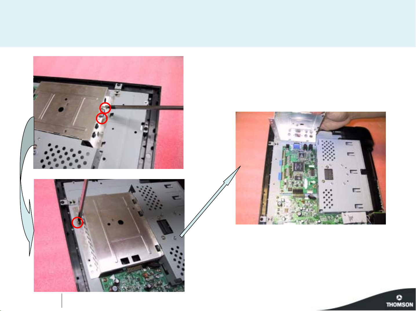
15 " LCD TV
Revision 1.0
Page N°7
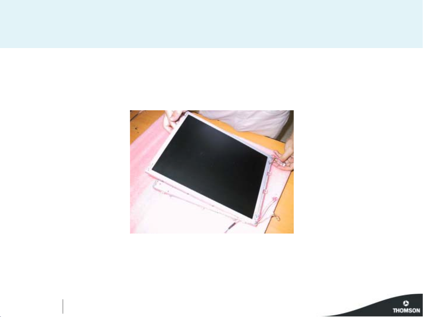
Page 13
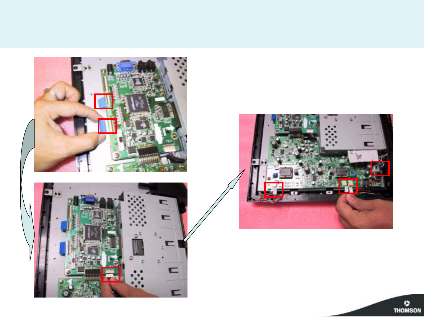
15 " LCD TV
Revision 1.0
Page N°8
Page 14
15 " LCD TV
Revision 1.0
Page N°9
Page 15
15 " LCD TV
Revision 1.0
Page N°10
Page 16
15 " LCD TV
Revision 1.0
Page N°11
Page 17
15 " LCD TV
Revision 1.0
Page N°12
Page 18
Disassembly
process
20LCDM03B
Page N°1
Page 19
20 " LCD TV
Revision 1.0
Page N°2
Page 20
20 " LCD TV
Revision 1.0
Page N°3
Page 21
20 " LCD TV
Revision 1.0
Page N°4
Page 22
20 " LCD TV
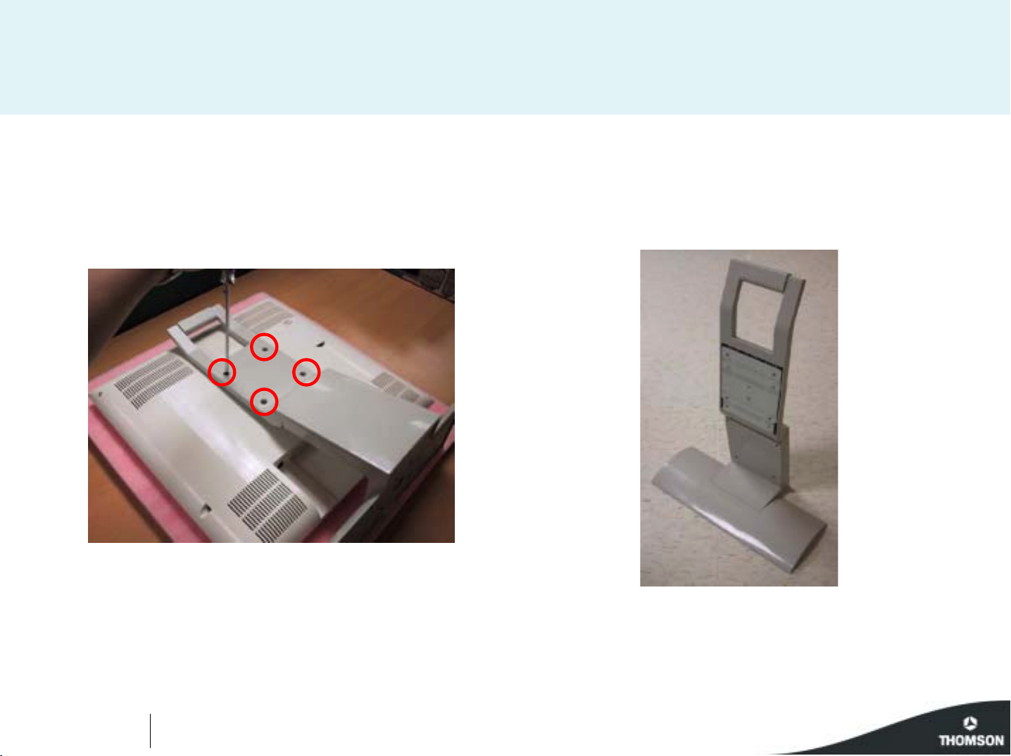
Boards overview
Power board
Inverter board
Earphone board
PC board
Power board
Revision 1.0
Control board
AV module
Page N°5
Page 23

20 " LCD TV
Revision 1.0
Page N°6
Page 24

20 " LCD TV
Revision 1.0
Page N°7
Page 25

20 " LCD TV
AV module
Revision 1.0
Page N°8
Page 26

20 " LCD TV
Revision 1.0
Page N°9
Page 27

20 " LCD TV
Revision 1.0
Page N°10
Page 28

20 " LCD TV
Revision 1.0
Page N°11
Page 29

20 " LCD TV
Revision 1.0
Page N°12
Page 30

20 " LCD TV
Revision 1.0
Page N°13
Page 31

LCD03B
10 First issue 04 / 04
Service Mode Operation Manual
Model support: 15” 20” and 20” bi-sonic
Service Mode
1. Press the “menu” button, and then the screen display will
appear “Overview” OSD, below as Figure Overview OSD.
Then press the “info” button and ”1”, ”0”and ”3” buttons
step by step to enter Service Mode. And Figure
Service mode will appear on the screen display.
Mode Service
1.Presser la touche “Menu” l’ecran de selection ci-dessus apparait
Prenez la touche “Info”, la touche “1” puis les touches “0” et “3” pour
acceder au “Mode Service”
Anleitung Service Mode
Für Modelle: 15“, 20“ und 20“ bi-sonic
Service Mode
1. Drücken sie die „MENU“ – Taste. Es erscheint das „Übersicht“
–Menü (siehe Abbildung 1). Drücken sie dann nacheinander die Tasten
„INFO“, „1“, „0“, und „3“. Die erste Seite des Service-Modes wird
angezeigt (siehe Abbildung 2).
Manuale Procedura Service Mode
Modelli: 15” 20” e 20” bi-colonna
Service Mode
1. Premere il tasto “menu” per far visualizzare il menu “Sommario”,
vedi pagina OSD.
Poi premere sequenzialmente i tasti “info” , “1”, “0” e “3” per entrare in
Service mode. Il menu di Service mode verrà visualizzata sullo schermo.
Per cambiare pagina premere il tasto “Menu”.
Menu Sommario
Manual de operación del Modo Servicio
Para modelos de : 15”, 20” y 20” bi-columna
Modo Servicio
1. Pulsar la tecla “menú”, en la pantalla se mostrará
el menú “OVERVIEW (ÍNDICE)”, como se muestra en
la figura MENU OVERVIEW (ÍNDICE).
A continuación, pulsar las teclas “info”, ”1”, ”0” y ”3” una tras otra
para entrar en Modo Servicio y se mostrará
la primera página del Modo Servicio en la pantalla.
Overview
Preferences
Installation
Sound
Picture
Figure Overview OSD
SERVICE MODE - MODE SERVICE - SERVICE-MODE - MODO SERVICIO
EN
FR
DE
ES
IT
➠
- “Change“ value
- Réglage de la valeur
- Wert “änden“
- “Cambiare“ valore
- “Cambiar“ valor
NAVIGATION INSIDE THE SERVICE MODE - DEPLACEMENT DANS LE MODE SERVICE
SUCHE IN SERVICE MODE - OPZIONI NEL SERVICE MODE - BUSQUEDA EN MODO SERVICIO
➠
REMOTE CONTROL - TELECOMMANDE - FERNBEDIENUNG
TELECOMANDO - MANDO A DISTANCIA
Naviagation up Naviagation down
VALUE
VALUE
>
<
- Press "Menu" button
- Appuyer sur la touche "Menu"
- Taste "Menu"
- Premere " Menu"
- Pulse "Menu"
Changing page - Changement de page
Seitenwechsel - Cambiare Pagina - Cambio de página
Choosing a setting from the menu / setting e value
Choix d'un réglage dans un menu / Réglage d'une valeur
Wahl einer einstellung in einem menü / Einstellung eines wertes
Scegliere una Regolazione dal Menu / Selezione di un valore
Eleccion de un Ajuste en un menu / Ajuste de un valor
Color temp P-N P-C V-CV-NP-W
Red Drive - 123 Green Drive
Blue Drive
Red Offset
Green Offset
Blue Offset
Reset To Default
Calibration...
Auto Turn on on off
-
-
-
-
-
-
Tuner 1D
+
+
- 123 -
+
- 123 -
+
- 123 -
+
- 123 -
- 123 -
+
190247
Eu 20L0BI
Ver 09171I
Color temp P-N P-C V-CV-NP-W
Red Drive - 123 Green Drive
Blue Drive
Red Offset
Green Offset
Blue Offset
Reset To Default
Calibration...
Auto Turn on on off
-
-
-
-
-
-
Tuner 1D
+
+
- 123 -
+
- 123 -
+
- 123 -
+
- 123 -
- 123 -
+
190247
Eu 20L0BI
Ver 09171I
Page 32

LCD03B
First issue 04 / 04
1. Color Temp: P-N means “Normal” on YpbPr, V-N means “Normal” on
Video mode. Each item decide different gamma curve.
2. Red drive, Green drive and blue drive means gamma RGB gain.
Control by scaler
3. Red offset, Green offset and blue offset means gamma RGB offset.
Control by scaler
4. Reset To Default: press OK will load all default value on User OSD
5. Calibration: press this botton guide to calibrate A/D converter white
and black level on PC input. Also guide to calibrate A/D converter PbPr
offset on YpbPr input
6. Auto Turn On: toggle on/off control auto turn on . this function for
factory burn-in sets . Only active on selection PC input then main power
off.
7. Green lable: Tuner s/w version, time while compiling s/w, model
name, main s/w version.
1. Color Temp: Temperature des couleurs.
P-N correspond à un reglage “Normal” /YpPr
V-N correspond à un reglage “normal” / mode vidéo
chaque item permet de règler la courbe de gamma.
2. Red drive, Green drive and blue drive: green drive et Bleu drive
correspond aux reglages de gain
du gamma RVB ( controlé par le scaler).
3. Red offset, green offset et blue offset: correspond aux réglage
d’offset du gamma RVB ( controlé par le scaler ).
4. Reset To Default: Appuyer sur “OK”.
Charger les valeurs par defaut sur le menu OSD.
5. Calibration: Appuyer sur “OK” pour valider.
Etalonne les niveaux blanc et noir du convertisseur A/D de l’ entrée PC
Etalonne egalement les offset Pb/Pr du convertisseur A/D sur l’ entrée
Ypb Pr
6. Auto Turn On: Option On/OFF valide le reglage usine,
le démarrage automatique. Seulement active sur l’entrée PC.
7. Green lable Indication dans les fenêtres vertes: Version software
tuner, temps de compilation software , nom du modele, version, version
du software principal.
Seite 1 des Service-Modes
1. Color Temp: P-W steht für „Warm im YPbPr-Mode, P-N steht für
„Neutral“ bei YPbPr-Mode, P-C steht für „Kalt“ im YPbPr,-Mode, V-W
steht für „Warm“ im Video-Mode, V-N steht für „Neutral“ im Video-Mode,
V-C steht für „Kalt“ im Video-Mode. Alle Modi haben unterschiedliche
Gamma-Kennlinien.
2. Red Drive, Green Drive und Blue Drive: Einstellung der RGBVerstärkung
3. Red Offset, Green Offset und Blue Offset: Einstellung des RGBOffsets
4. Reset to Default: Durch Drücken der “OK”-Taste werden die
Benutzerdaten gelöscht und die Defaultwerte geladen.
5. Calibration: Kalibrieren der Schwarz- und Weißpegel des ADWandlers des PC-Eingangs
6. Auto Turn On: Aktivierung des automatischen Einschalten des
Gerätes über den PC-Eingang. (nur für den Burn-In in der Farbrik
vorgesehen).
7. Grün markierte Felder: Software-Version Tuner, Compiler-Daten,
interne Modellbezeichnung, Version der Hauptsoftware.
1. Color Temp: P-N significa “Normale” in funzione YPbPr, V-N significa
“Normale” in funzione Video. Ogni selezione determina una differente
curva di risposta.
2. Red Drive, Green Drive e Blue Drive significa guadagno gamma
RGB. Controllato da una scala.
3. Red Offset, Green Offset e Blue Offset significa Offset gamma RGB.
Controllato da una scala.
4. Reset To Default: premendo OK verranno caricati tutti i valori di
Default nel Menu Utente.
5. Calibration: premere questo tasto guida per calibrare il livello Bianco
/Nero del convertitore A/D dell’ingresso PC. Calibra anche l’offset del
convertitore A/D PbPr dell’ingresso YpbPr.
6. Auto Turn On: Commutatore controllo automatico On/Off. Funzione
utile per le prove di bruciatura in fabbrica. Attivando On si attiva lo
spegnimento automatico in base al segnale di ingresso PC.
7. Caselle in Verde: Versione Software Tuner, Data compilazione
Software, Nome modello, Versione software Main.
1. Color Temp: P-N significa “Normal” en modo YpbPr, V-N significa
“Normal” en modo Video. Cada elemento tiene una curva de gamma
distinta.
2. Red drive, Green drive y Blue drive ajustan la ganancia de la gamma
RGB.
3. Red offset, Green offset y Blue offset ajustan el offset de la gamma
RGB.
4. Reset To Default: Al pulsar OK se cargarán todos los valores por
defecto del menú de usuario
5. Calibration: Pulsando este botón ayuda a calibrar el convertidor A/D
de nivel de blanco y negro
para la entrada de PC. También sirve para calibrar el offset del
convertidor A/D PbPr en la entrada YpbPr
6. Auto Turn On: Selecciona el control del autoencendido. Sólo activo
en la selección de entrada de PC y desconexión de red.
7. Casillas en verde: versión de software del sintonizador, datos de
compilación del s/w, modelo, versión del s/w principal
Color temp P-N P-C V-CV-NP-W
Page1 on service mode
EN
FR
DE
ES
IT
Red Drive - 123 Green Drive
Blue Drive
Red Offset
Green Offset
Blue Offset
Reset To Default
Calibration...
Auto Turn on on off
-
-
-
-
-
-
Tuner 1D
+
+
- 123 -
+
- 123 -
+
- 123 -
+
- 123 -
- 123 -
+
190247
Eu 20L0BI
Ver 09171I
Page 33

LCD03B
First issue 04 / 04
8. OSD position: OSD position selection.
9. Factory Save: press OK save all parameters on service mode.
10. Auto Adjustment: auto adjustment new timing(position ,phase…etc).
Only active on PC mode.
11. Video int Gain: this slider bar used to align brightness spec of Video
mode. Larger value bring to brighter. Control by Video decoder VPC3230
12. Colour: adjust color saturation. Same funct ion on User OSD. Control
by Video
decoder VPC3230.
13. Tuner Set V-Level: not used
14. Tuner Get V-Level: not used.
15. Set First Installation: “Enable” means TV will pop-up installation
OSD at next power-on.
16. Tuner Set Factory Programs: not used.
17. EXIT: exit service mode.
8. OSD position: Selection de la position OSD.
9. Factory Save: pressez la touche “OK” pour sauvegarder tous les
parametres du mode service
10.Auto Adjustment: Actif seulement en mode PC. Auto réglage des
nouveaux parametres de temps ( Position, phase..).
11. Video int Gain: Réglage de la lumière en mode vidéo.
Contrôle par le décodeur vidéo VP¨C 3230.
La position élevèe du curseur augmente la lumière.
12. Colour: Régle la saturation de la couleur.
13. Tuner Set V-Level:Pas utilisé.
14. Tuner Get V-Level: Pas utilisé.
15. Set First Installation: Signifie que la TV à la prochaine mise sous
tension affichera le menu d’ installation.
16. Tuner Set Factory Programs: Pas utilisé.
17. EXIT: Sortie du mode Service.
Seite 2 des Service-Modes
8. OSD Position: Wahl der Menü-Position auf dem Bildschirm
9. Factory Save: Drücken der „OK“-Taste speichert alle Einstellungen
des Service-Modes ab.
10. Auto Adjustment: Automatischer Abgleich von Timing, Lage, Phase
usw. im PC-Mode
11. Video Int Gain: Helligkeitsvoreinsteller für den Video-Mode.
Steuerung über den Videodecoder VPC3230.
12. Colour: Einstellung der Farbsättigung; gleiche Funktion wie die
Benutzersteuerung. Steuerung über den Videodecoder VPC3230.
13. Tuner Set V-Level: nicht benutzt
14. Tuner Get V-Level: nicht benutzt
15. Set First Installation: „Enable“ lässt beim nächsten Einschalten des
Gerätes nach einer Netztrennung das Installationsmenü erscheinen.
16. Tuner Set Factory Programs: nicht benutzt.
17. Exit: Verlassen des Service-Modes.
8. OSD position: Selezione posizione OSD.
9. Factory Save: Premere OK per salvare tutti i parametri del service
Mode.
10. Auto Adjustment: Auto regolazione nuove temporizzazioni
( posizione, fase ... etc). Attivo solo in funzione PC.
11. Video int Gain: Regola il livello di luminosità in funzione Video. Più
alto è il valore più l’immagine è luminosa. Controllo tramite il Decoder
Video VPC3230.
12. Colour: Regola la saturazione del colore. Stessa funzione del Menu
utente. Controllo tramite Video Decoder VPC3230.
13. Tuner Set V-Level: Non utilizzato.
14. Tuner Get V-level: Non utilizzato.
15. Set First Installation: “Enable” significa abilitazione, all’accensione,
del menu di prima installazione.
16. Tuner Set factory Programs: Non utilizzato.
17. EXIT: Uscita dal Service Mode.
8. OSD position: Selecciona la posición del OSD.
9. Factory Save: Al pulsar OK, se guardan todos los parámetros del
modo servicio.
10. Auto Adjustment: Autoajuste de nuevo timing (posición, fase…etc).
Sólo activo en modo PC.
11. Video int Gain: Esta barra deslizante se utiliza para ajustar las
especificaciones del brillo en el modo Video. Cuanto mayor sea el valor,
más brillante. Control por el descodificador de Video VPC3230
12. Colour: ajusta la saturación del color. Es la misma función que el
menú de usuario. Control por el descodificador de Video VPC3230.
13. Tuner Set V-Level: no utilizado.
14. Tuner Get V-Level: no utilizado.
15. Set First Installation: “Enable” significa que la próxima vez que se
conecte el TV aparecerá el menú de primera instalación.
16. Tuner Set Factory Programs: no utilizado.
17. EXIT: Salida del Modo Servicio.
OSD Position
Page2 on service mode
EN
FR
DE
ES
IT
Factory Save...
Auto Adjustment
Video Int Gain
Colour
-
-
Tuner Set V-Level
Tuner Get V-Level
Set First INstallation NotEnabled...
Tuner Set Factory Programs
Exit
+
+
- 123 -
- 123 -
Page 34

LCDB03B
First issue 04 / 04
18. PW Gamma: gamma curve selection. “Automatic” means pick-up
proper gamma curve automatically when user choose Normal, Warm and
Cool. Value change is not recommended.
19. Scale Mode: screen ratio selection.
20. VPC AGC ON: turn on Video decoder “Auto gain control” (analog input
level adjustment.).
21. VPC AGC OFF: turn off Video decoder “Auto gain control”.
22. HV Lock Sensitivity: Tuner HV sync sensitivity. Value change is not
recommended. Fake programme be detected or Real programme be
skipped.
23. Color Delay: Color timing delay which only impact on Video mode. For
development only. Value change is not recommended
24. Audio gain: not used.
25. Pb offset: adjust Pb offset on YpbPr input.
26. Pr offset: adjust Pr offset on YpbPr input.
These 2(25,26) Functions above could be automatically done by
“Calibration” page1.
27. Enter PW1230 Adjustment page: Deinterlacer parameters control. For
development only. Value change is not recommended.
18. PW Gamma: Selection de la courbe de gamma “Automatic”
correspont à l’optention de la courbe de gamma appropriée quand
l’utilisateur choisit la position froide, neutre, chaude ou le rendu des
couleurs est meilleur.
il est deconseillé de sélectionner la position “value Change”.
19. Scale Mode: Selection format d’ecran.
20. VPC AGC ON:Active le Vidéo décodeur. Sélectionnez “ Auto gain
Control” ( réglage du niveau d’entrée analogique ).
21. VPC AGC OFF:Désactive le Vidéo décodeur. Sélectionnez “ Auto
gain Control”.
22. HV Lock Sensitivity: Sensibilité de la Synch. HV tuner.
Il est imperatif de ne pas modifier sa valeur.
Le tuner détectera les mauvais progrmmes ou passera les programmes
corréctes.
23. Color Delay: Réglage du “délai” couleur en mode vidéo.
Réglage usine, ne pas modifier.
24. Audio gain: Non utilisé.
25. Pb offset: Réglage de l’offset Pb sur l’ entrée Ypb Pr.
26. Pr offset: Réglage de l’offset Pr sur l’entée Ypb Pr.
Ces 2 réglages ( 25, 26 ) sont automatiquement effectues par
“calibration” de la page 1 du mode service.
27. Enter PW1230 Adjustment page: Ne pas modifier. Réglage usine
Contrôle les parametres “ Deinterlacer”.
18. PW Gamma: Auswahl der Gamma-Kennlinie: Bei Einstellung
„Automatic“ wird automatisch die jeweilige Kennlinie gewählt, wenn der
Benutzer zwischen Warm, Neutral oder Kalt umschaltet. Eine Änderung
dieser Grundeinstellung ist nicht empfehlenswert.
19. Scale Mode: Wahl des Bildformates
20. VPC AGC ON: Aktiviert die automatische Verstärkungsregelung des
Videodecoders (Anpassung der Pegel der Analogeingänge)
21. VPC AGC OFF: Deaktiviert die automatische Verstärkungsregelung
des Videodecoders.
22. HV Lock Sensitivity: Empfindlichkeit des Synchrondetektors im
Tuner. Eine Änderung dieser Grundeinstellung ist nicht empfehlenswert,
da sonst der Sendersuchlauf falsche Ergebnisse liefern könnte.
23. Color Delay: Einstellung Farbversatz. Eine Änderung dieser
Grundeinstellung ist nicht empfehlenswert.
24 Audio Gain: nicht benutzt
25. Pb Offset: Einstellung des Pb Offsets bei YPbPr.
26. Pr Offset: Einstellung des Pr Offsets bei YPbPr.
Zu 26 und26: Der Abgleich dieser Funktionen kann automatisch mit der
Funktion „Calibration“ auf der Service-Mode Seite 1 durchgeführt werden.
27. Enter PW1230 Adjustment Page: Abgleich der Parameter des
Deinterlacers. Eine Änderung dieser Grundeinstellungen ist nicht
empfehlenswert.
18. PW Gamma: Selezione curva gamma. In “Automatic” viene
selezionata automaticamente la curva gamma ideale, in base alla scelta
utente Calda, Fredda o Neutra, nella funzione Tonalità . Si consiglia di
non cambiare valore.
19. Scale Mode: Selezione Rapporto schermo.
20. VPC AGC ON: Attiva, nel Decoder Video, il Controllo automatico del
Guadagno (Regolazione livello ingresso analogico).
21. VPC AGC OFF: Disabilita, nel Decoder Video, il Controllo Automatico
del Guadagno.
22. HV Lock Sensitivity: Sensibilità Sync HV Tuner. Si consiglia di non
cambiare valore. Livello soglia per saltare eventuali emittenti con segnale
debole.
23. Color Delay: Regola il ritardo colore rispetto al segnale video.
Utilizzato per la fabbrica. Si consiglia di non cambiare valore.
24. Audio Gain: Non utilizzato.
25. Pb offset: Regola l’offset Pb sul segnale YpbPr in ingresso.
26. Pr offset: Regola l’offset Pr sul segnale YpbPr in ingresso.
Le regolazioni menzionate nei punti 25 e 26 possono essere eseguite
automaticamente come indicato nella riga “Calibration” di pagina 1.
27. Enter PW Adjustment page: Controllo parametric Deinterlacer.
Utilizzato in fabbrica. Si consiglia di non cambiare valore.
18. PW Gamma: Selección de la curva de gamma. “Automatic” quiere
decir que recuperará automáticamente la curva ideal de gamma cuando
el usuario seleccione Normal, Cálido o Frío. No se recomienda cambiar
este valor.
19. Scale Mode: selecciona la relación de pantalla.
20. VPC AGC ON: activa el "control automático de ganancia" del
descodificador de video (ajuste del nivel de entrada analógica).
21. VPC AGC OFF: desactiva el "control automático de ganancia" del
descodificador de video.
22. HV Lock Sensitivity: Sensibilidad de los sincronismos HV del
sintonizador para la búsqueda de emisoras. No se aconseja cambiar este
valor. Los canales reales pueden ser ignorados o los falsos
memorizados.
23. Color Delay: Retardo del color en modo Video. No se recomienda
cambiar este valor
24. Audio gain: no utilizado.
25. Pb offset: ajuste del offset de Pb en la entrada YpbPr.
26. Pr offset: ajuste del offset de Pr en la entrada YpbPr.
Estas 2 funciones anteriores (25,26) serán hechas automáticamente en
“Calibration” de la página 1.
27. Enter PW1230 Adjustment page: control de los parámetros de
Deinterlacer. No se recomienda cambiar este valor.
36. V. Position: ajusta la posición Vertical sobre la entrada PC.
Pw Gamma Automatic
Page3 on service mode
EN
FR
DE
ES
IT
Scale Mode
VPC AGC ON
VPC AGC OFF
HV Lock Sensitivity
Color Delay
Audio Gain
Pb Offset NotEnabled...
Pr Offset
-+
-
-
-+
-+
+
+
- 123 -
- 123 -
- 123 -
- 123 -
- 123 -
Enter PW1230 Adjustment Page...
Page 35

LCD03B
First issue 04 / 04
28. Video Format: select Video standard. Force to “Auto”.
29. Default Language: set default language. Same function on User
OSD.
30. RGB filter: sharpness filter of PC port of scaler. Impact on PC and
YpbPr input
31. Video filter: sharpness filter of Video of scaler. Impact on TV Video
and YcbCr.
32. Monitor Sync: force to “On”. So that Video format can auto
detection.
33. Reset All Nvram: press “OK” will reset all parameters on service
mode, including color temp settings, brightness setting….etc.
34. Test Pattern: display test-pattern which generate by scaler. Only
active on PC source.
35. H.Position: adjust horizontal position while PC source in
36. V.Position: adjust Vertical position while PC source in
28. Video Format: selectionne le standard Vidéo. Forcer à “Auto”.
29. Default Language: Selectionne la langue par défaut. Même fonction
que le réglage utilisateur.
30. RGB filter: Filtre Contour RGB du Port PC.
Agit sur les entrées PC et Ypb Pr.
31. Video filter: filtre contour Vidéo. Agit sur les entrées TV Vidéo et
Ye bCr.
32. Monitor Sync: Forcé à ON Auto détection du format Vidéo.
33. Reset All Nvram: Appui sur “OK”.
Reset De tous les parametres du “MODE SERVICE” incluant la
tempèrature de couleur, Contour... etc.
34. Test Pattern: Affichage de la mire interne. Actif seulement en mode
PC
35. H.Position: Réglage Horizontal en mode PC.
36. V.Position: Réglage Vertical en mode PC.
28. Video Format: Auswahl des Videostandards. Sollte auf „Auto“
stehen.
29. Default Language: Auswahl der Menüsprache; gleiche Funktion wie
die Benutzersteuerung.
30. RGB Filter: Abgleich des Schärfefilters des Scalers für PC-Mode und
YPbPr.
31. Video Filter: Abgleich des Schärfefilters des Scalers für den VideoMode.
32. Monitor Sync: Sollte immer auf „On“ stehen damit das Videoformat
automatisch erkannt wird.
33. Reset All Nvram: Drücken der „OK“-Taste setzt alle Parameter im
Service-Mode ( auch Farbtemparatur, Helligkeit usw.) zurück.
34. Test Pattern: Zeigt ein vom Scaler erzeugtes Testmuster auf dem
Bildschirm. Nur im PC-Mode.
35. H.Position: Horizontallage für PC-Eingang.
36. V.Position: Vertikallage für PC-Eingang.
28. Video Format: Seleziona lo standard Video. Forzato su “Auto”.
29. Default language: Seleziona la lingua. Stessa funzione del Menu
Utente.
30. RGB Filter: Definizione filtro del demoltiplicatore (scaler) della porta
PC. Influisce sugli ingressi PC e YpbPr.
31. Video Filter: Definizione filtro del demoltiplicatore del segnale Video.
Influisce sui segnali TV Video e YcbCr.
32. Monitor Sync: Forzato su “On”. In questo modo può essere rilevato
automaticamente il Formato Video.
33. Reset All Nvram: Premendo “OK” verranno resettati tutti I
parametri del Service Mode, inclusi regolazione Temp. Colore,
Regolazione Luminosità, ... ecc.).
34. Test Pattern: Attivazione serie di segnali test. Attivo solo con
ingresso PC.
35. H. Position: Regola la posizione Orizzontale in ingresso PC.
36. V. Position: Regola la posizione Verticale in ingresso PC.
28. Video Format: selecciona el estándar de Video. “Auto” fuerza a
modo automático.
29. Default Language: selecciona el idioma por defecto. Hace la misma
función que el menú "Usuario".
30. RGB filter: filtro de nitidez. Válido para las entradas de PC e YpbPr.
31. Video filter: filtro de nitidez. Válido para las entradas de TV, Video e
YcbCr.
32. Monitor Sync: forzado a “On”. El formato de video puede ser
autodetectado.
33. Reset All Nvram: pulsando “OK” se borrarán todos los parámetros
del Modo Servicio, incluyendo los ajustes de temperatura de color,
ajustes de brillo y contraste....., etc.
34. Test Pattern: muestra unas cartas de ajuste generadas
internamente. Activo solamente en modo PC.
35. H. Position: ajusta la posición horizontal sobre la entrada PC.
36. V. Position: ajusta la posición Vertical sobre la entrada PC.
Video Format NTSC-M
Page4 on service mode
EN
FR
DE
ES
IT
Scale Mode
RGB Filter
Video Filter
Monitor Sync On Off
Reset All Nvram
Test Pattern NotEnabled...
H.position
-+
-+
V.position
- 123 -
- 123 -
Page 36

LCD03B
First issue 04 / 04
37. Life Time: The left item means the time added by stand by + TV on
The right item display the time of TV-on only.
38. Project Code: as title
39. Panel Resolution: as title
40. NvRam Ver. Display EEPROM data veriosn.
41. HXV Res / Hfreq: timing information. Resolution and H clock
42. HXV Total: timing information.
43. Mode Num: timing information. Sequence of Timing chart.
44. DCLK: timing information. Data clock
These 4(41,42,43,and 44) items above are for development check only.
45. Factory save: save factory parameters.
46. Green label: display tuner s/w version.
37. Life Time:
-Indication de gauche:
indique le temps fonctionnement total du TV: On+ Stand by.
-Indication de droite:
Indique le temps de fonctionnement du TV en On seulement.
38. Project Code: Info code.
39. Panel Resolution: Resolution du panneau d’écran.
40. NvRam Ver. Version EEPROM.
41. HXV Res / Hfreq: Information de temps resolution et Horloge H.
42. HXV Total: Information de temps.
43. Mode Num: Information de temps
44. DCLK: Information de temps.
Data clock.
Ces 4 lignes d’information sont utilisées en développement.
45. Factory save: Sauvegarde les paramétres usine.
46. Green label: Affiche la version de Software du tuner.
Seite 5 des Service-Modes
37. Life Time: Betriebsstundenzähler, links: Summe Standby-Zeit und
TV-Ein, rechts: nur TV-Ein-Zeit.
38. Project Code:
39. Panel Resolution: Auflösung der LCD-Panels
40. NvRam Ver. : Version EEPROM-Daten
41. HXV Res / HFreq:Timing-Information (Auflösung und H-Clock)
42. HXV Total: Timing Information
43. Mode Num Timing Information
44. DCLK: Timing Information Data Clock
45. Factory Save: Daten des Service-Modes speichern.
46. Grün hinterlegtes Feld: Version Tuner-Software
37. Life Time: Il contatore a sinistra indica il tempo totale di
funzionamento in Stand By + apparecchio acceso. Il contatore a destra
indica il tempo totale di funzionamento ad apparecchio acceso (ON).
38. Project code: Codice progetto.
39. Panel Resolution: Risoluzione pannello.
40. NvRam Ver: Versione EEPROM.
41. HXV res / Hfreq: Informazione timing. Risoluzione e Clock H.
42. HXV Total: Informazioni timing.
43. Mode Num: Informazioni Timing. Sequenza carta tempi.
44. DCLK: Informazioni Timing. Clock Data.
I valori menzionati nei punti 41, 42 43 e 44 sono solo per la fabbrica
45. Factory save: Parametri memorizzati in fabbrica.
46. Casella verde: Versione software Tuner
37. Life Time: Los números de la izquierda muestran la suma de las
horas en stand-by + TV encendido. Los de la derecha indican sólo las
horas de TV encendido.
38. Project Code: informativo
39. Panel Resolution: informativo
40. NvRam Ver. Indica la versión de la EEPROM.
41. HXV Res / Hfreq: información de timing. Resolución y frecuencia H.
42. HXV Total: información de timing.
43. Mode Num: información de timing.
44. DCLK: información de timing. Frecuencia del reloj.
Estas 4 funciones anteriores (41,42,43,y 44) son informativas. Sólo son
para comprobación.
45. Factory save: memoriza los valores de fábrica.
46. Casilla en verde: indica la versión de software del sintonizador.
Life Time 00034:10 00033:35
Page5 on service mode
EN
FR
DE
ES
IT
Project Code EU20L03B
Panel Resolution 800 X 600
NvRam Ver. OC / 14
HXV Res / HFreq 649 X 548 15,52
HXV Total 864 X 625
Mode Num 55
DCLK 41.0 M
Tuner: 1DFactory Save...
Page 37

LCD03B
First issue 10 / 03
CONTROL SCHEMATIC DIAGRAM - SCHEMA DES CIRCUITS COMMANDES - SCHALTBILD BEDIENTEIL - SCHEMA DEI CIRCUITI COMANDI - ESQUEMA DE LOS CIRCUITOS MANDOS
CONTROL 20” BI)
12V
J3
20L1033010
G1 G2
G1 G2
16V
R1 0
51.1KF
R9
1K
R1 1
51.1KF
R8
1K
13
SW4
1N4148
Q3
2N3904
12V
R1 4
47K
D7
J1
7
7
6
6
1
1
2
2
4
4
5
5
3
3
2210165091
32
Q2
1
2N3 904
12
R1 5
C1 4
+
100U
16V
10K
C1 5
+
100U
16V
R7
1K
C1 2
+
100U
16V
C1 6
+
100U
16V
7
8
6
5
C1 3
+
100U
16V
13
SW3
2
+
-
+
-
1
3
4
TDA2 822D
13
SW2
R5
C1 0
+
16V
100U
C1 1
+
16V
100U
U1
39
R1 2
4.7
R6
C6
0.1U
25V K
13
SW1
39
R1 3
4.7
C7
0.1U
25V K
V5S
D1
TZMC 5V1
D4
TZMC 5V1
D2
TZMC 11
D5
TZMC1 1
R3
10K
R4
10K
C1
1000P
C2
1000P
C3
100 0P
D3
TZMC 5V1
D6
TZMC 5V1
12V
J2
EAR_MUTE
TP 1
5
TP 2
TP 3
TP 4
TP 5
TP 6
TP 7
TP 8
TP 9
TP 10
TP 11
TP 12
TP 13
TP 14
TP 15
Audio_R
Audio_L
V5S
KP D0
KP D1
KP D2
KP D3
KP D4
KP D5
R2
10K
13
SW6
4
3
2
1
G1 G2
10
10
10
9
9
9
8
8
8
7
7
7
6
6
6
5
5
5
4
4
4
3
3
3
2
2
2
1
1
1
R1
10K
+
16V
10U
C9
10U
13
Q1
2N3 906
+
C4
SW5
H1
HOLE -V8
6
6
7
7
8
8
9
9
245
H2
HOLE -V8
2
2
3
3
4
4
5
5
1
1
6
6
7
7
8
8
9
9
2
2
3
3
4
4
5
5
1
1
245
245
Optical Points
OP
OP8 OP14OP11
OP
245
OP2 OP4
OP
OP
OP
OP10
OP
OP
245
OP5OP1
OP
OP12OP9
OP
OP6OP3 OP7
OP
OP13
OP
OP
OPOP
245
20L 0BI
KEY PA D BOAR
48.M2302.A00
W ednesday , Septem ber 24, 2003
Page 38

LCD03B
First issue 10 / 03
IR PREAMPLIFIER - IR PREAMPLIFICATEUR - IR VORVERSTARKER - PREAMPLICATORE IR
( IR PREAMPLIFIER 20”BI )
IR Sensor P/N :05.04856.010 for the USA
IR Sensor P/N :05.04833.010 for the EU
U1
R4
33 0
R1
33 0
TSOP4856
V5S
J3
12
11
10
9
8
7
6
5
4
3
2
1
20L1033012
4
RG
2
V5S
12
11
10
9
8
7
6
5
4
3
2
1
TP 1
TP 2
TP 3
TP 4
TP 5
TP 6
TP 7
TP 8
TP 9
TP 10
L2
L3
L4
KP D0
KP D1
KP D2
KP D3
KP D4
KP D5
V5S
G2
LE D1
GREEN/RED
13
TP16
TP13
TP14
TP15
TP18OPTP19
TP17
4
5
678
9
10
456
7
8
9
10
J2
20L1033010
TP20
VOUT
GND
VCC
123
12
C1
+
4.7U
25V
123
123
G1
G1G2
R2
330
R3
5.1K
IR BOARD
H1
HO LE-V 8
6
7
8
9
Optical Points
OP
OP2 OP4 OP6OP3 OP7OP5OP1
OP
2
3
4
5
1
OP OP
OP
H2
HOL E-V8
6
7
8
9
OP
2
3
4
5
1
Page 39

LCD03B
First issue 10 / 03
AUDIO CHANNEL SCHEMATIC DIAGRAM - SCHEMA DES CIRCUITS AUDIO - SCHALTBILD MEHRKANAL AUDIO - SCHEMA DEI CIRCUITI AUDIO - ESQUEMA DE LOS CIRCUITOS AUDIO
(AUDIO 20” BI)
R564
+12V
2K
R565
2K
R566
2K
R567
2K
BD501
(0805)
(Bead)
BD503
(Bead)
ZD557
12V
PWR_GND
BD502
(Bead)
BD504
VCC 2
CN601
1
22
3
4
(Bead)
CN602=>
CN602
AUD_L
AUD_R
MUTE
S-GND
EAR_MUTE
C507
100µ
16V
(el)
R515
47K
C510
0.1µ
16V
C511
0.1µ
16V
AUD_L
AUD_R
R507
10K
R517
20K
R501
26,1K
R502
26,1K
R518
47K
Q506
2N3904
R514
20K
VCC
R513
47K
Q504
2N3904
R503
10K
S_GND
R513
20K
Q505
2N3904
S_GND
R516
20K
R512
20K
S_GND
AUD_L
C501
1000P
50V
C502
10009
50V
Q503
2N3904
S_GND
R506
47K
S_GND
R504
10K
C508
0.22µ
16V
R505
47K
S_GND
C504
0,22µ
16V
C503
10µ
16V
(EL)
C509
470µ
25V
IEL)
P_GND
Q501
2N3904
R508
20K
P_GND
S_GND
C505
470µ
25V
(ELI
4
IN1
7
ST-BY
9
S_GND
12
IN2
6
MUTE
8
PW-GBD
Q502
2N3904
C506
0,1µ
25V
Vref
R509
47K
R510
20K
3VCC 13
R511
47K
NOTES:
+19V
IC501
TDA7266
OUT1+
1
OUT1-
OUT2+
15
14
OUT2-
ZD 501
9.1V
1. Resistor values are in ohm, K = 1,000 ohm, M = 1,1000 000 ohm
2. All resistors are SMD 0603 5% exept where otherwise indicated
3. All capacitors are SMD 0603 5% exept where otherwise indicated
4. Represents PCB common ground
Page 40

LCD03B
First issue 10 / 03
DC - DC CONVERTER SCHEMATIC DIAGRAM - SCHEMA CONVERTISSEUR DC -DC -SCHALTBILD GLEICHSTROMUMFORMER - SCHEMA CONVERTITORE CC - CC
ESQUEMA CONVERTIDOR CC - CC
( DC/DC 15” )
POWER_ON
CN701
PWR-JACK
CN702
Page 41

LCD03B
First issue 10 / 03
DC - DC CONVERTER SCHEMATIC DIAGRAM - SCHEMA CONVERTISSEUR DC -DC -SCHALTBILD GLEICHSTROMUMFORMER - SCHEMA CONVERTITORE CC - CC
ESQUEMA CONVERTIDOR CC - CC
( DC/DC 20” BI )
+19V
SCP
R706
10K
R703
10K
R702
10K
1 CN+
C710
4700P
50V
1 CN-
R704
20K
1 FBK
1 DTC
1 OUT
UREF
C714
470P
50V
(NPD)
12345678
CT
IC701 TL1451AC
SCP
1 CN+
2 CN-
2 FBK
2 DTC
R709
47k
2 OUT
REF
16
15 14 13 12 11 10 9
C713
4700p
50V
R705
10k
R708
10k
R707
20k
R738
3K
DTC
GND
VCC
R710
0
F702
T 2A
69.420D1.111
F701
T 3A
69.43001.101
UREF
C709
1µ
25V
UREF
R739
3K
12V
ZD703
C716
1µ
16V
ZD704
12V
C702
220µ
25V
(el)
C715
1µ
16V
R714
R713
47K
+12V
R719
1.8K
R715
1,8K
ZD702
2MM 5,1V
Q705
2N3904
Q703
2N3904
R721
0
Q706
2N3904
R717
Q704
2N3905
ZD702
2MM 6,1V
C718
0.1µ
25V
+5VS
C719
0.1µ
25V
Q701
IRFR5305
D701
RB060L-4D
Q702
IRFR5305
D702
RB060L-4D
L701
150µ
D703
RB060L-4D
L702
47µ
D704
RB060L-4D
C705
220µ
25V
(EL)
C706
220µ
25V
(el)
R723
3 01K
R726
8,66K
R724
1K
R727
1K
C707
0,1µ
25V
R725
330
C708
0,1µ
25V
R729
47K
R728
2K
Q708
2N3904
+12V
UREF
R730
20K
R732
20K
Q707
FO59435
R733
3K
Q710
2N3904
Q709
2N3906
C704
47µ
16V
R731
47K
DTC
R734
47K
Q710
2N3904
+5VS
VCC
POWER_ON
R735
47K
BD701
(Bead)
BD702
(Bead)
CN701=>CN502
C701
220µ
25V
PWR_GND
2
4
3
1
+15V
BD501
CN701<=CN502
(Bead)
BD502
(Bead)
CN703
C501
470µ
25V
(ELI)
8
7
6
5
4
3
2
1
+19V
LCD_BR
1
2
3
GND
ON/OFF
PWR_GND
C717
220µ
25V
+19V
NOTES:
Q712
2N3906
+5VS
R740
20K
ON/OFF
LCD_ON
R741
3K
Q713
2N3904
1. Resistor values are in ohm, K = 1,000 ohm, M = 1,1000 000 ohm
2. All resistors are SMD 0603 5% exept where otherwise indicated
3. All capacitors are SMD 0603 5% exept where otherwise indicated
4. Represents PCB common ground
R743
20K
R742
47K
MUTE
AUDIO_L AUDIO_R
C564
0,1µ
25V
LCD_ON
+12V
+5VS
+19V
PWR_ON
(Bead)
VCC
0,1µ
25V
(Bead)
L502
L503
CN702
1
3
5
7
9
11
13
15
18
20
R737
2
4
6
8
10
12
14
17
19
21
LCD_BR
PWR_GND
S_GND
L501
(Bead)
C562
0,1µ
25V
20K
R736
20K
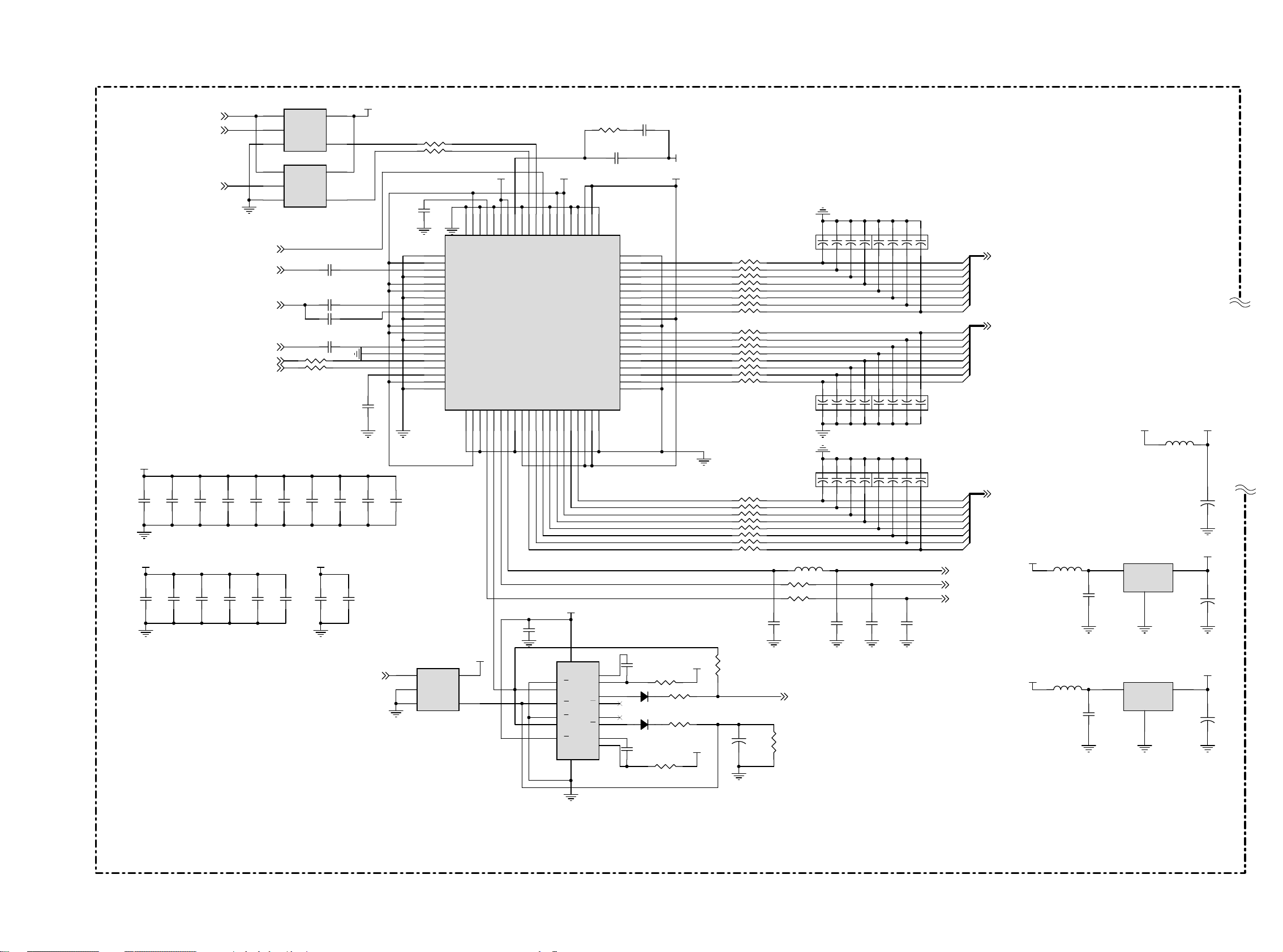
Page 42

LCD03B
First issue 10 / 03
INVERTER SCHEMATIC DIAGRAM - SCHEMA DE LA PLATINE INVERSEUR - SCHALTBILD INVERTER - SCHEMA INVERTER - ESQUEMA DEL INVERSOR
( INVERTER 15” / 20” )
CN601
CN604
CN603
CN602
Page 43

LCD03B
First issue 10 / 03
PC BOARD INTERFACE - INTERFACE PC BOARD - SCHALTBILD PC BOARD - SCHEMA DELLA PC BOARD INTERFAZ PC BOARD
( PC BOARD 1/7)
input output
TP5
GS DA
TP7
TP1 0
TP1 1
GS CL
11
12
13
14
15
16
J3
D-Sub15
17
+5VS
DN1
BAV99 C2
6
1
7
2
8
3
9
4
10
5
P C_5V
TP9
R1
TP3
TP6
G1
B1
TP8
R8
75
R2 47
R4 47
R5 47
R10
R9
75
75
1
D19
27V
C3
47P
50V J
1
D2 0
27V
C4
47P
50V J
C 121
10U
C 122
10U
C 123
10U
C5
47P
50V J
TZMC5V1
D6
TZM C5V1
D5
+
16V
+ +
16V
16V
TZMC5V1
D8
TZM C5V1
D7
DN2
BAV99
DN3
BAV9 9
+9 V OP5 V
R22
R2 3
150
150
D9
TZMC5V1
RED_ IN
GREEN_IN
BLUE_ IN
[P.2]
[P.2]
[P.2]
OP5 V
C 124
0.1U K
RED_ IN
C90
+
47U
16V
C 125
0.1U K
G REEN_I N
C 126
0.1U K
BLUE_ IN
24
U24
VCC
31
*2
GND
MM1031XMR
R138
OP5 V
24
U25
VCC
31
*2
GND
MM1031XMR
R139
OP5 V
24
U26
VCC
31
*2
GND
MM1031XMR
R140
0
0
0
R110
75 R6
R115
75
R120
75
VR_ IN
VR _GND
VY_ IN
VY_GND
VB_IN
VB_GN D
[P.1]
[P.1]
[P.1]
[P.1]
[P.1]
[P.1]
[P.1]
221 0165031
[P.6]
[P.6]
J2
7
7
6
6
1
1
2
2
4
4
5
5
3
3
Aud io_L_Lin e
Audio_ R_Line
1000P J
(For EMI)
TP2
TP4
C1
1000P J
D15
TZMC5V1
12
12
D16
TZMC5V1
600 OHM
R85
R86
600 OHM
D11
TZM C5V1
12
1
D12
TZM C5V1
(For EMI)
600 OHM
R87
600 OHM
R88
C1 30
D17
1000P J
TZMC5V1
12
12
D18
TZMC5V1
R1
R3
D13
12
1
D14
TZM C5V1
TZM C5V1
1K
1K
7
6
1
2
C1 31
10 00P J
4
5
3
Audio Line out(22 10165031 )
10K
[P.6]
LI3
RI3
[P.6]
R7
10K
J1
7
6
1
2
4
5
3
+5VS
2
1
Screw Holes
5
4
3
2
H1
HOLE-V8
BAV99
3
1
R136
2
1
R137
DN 9
BAV9 9
3
GS DA
4.7K
GS CL
1K
1K
R1 5
4.7K
+5VS
P C_5V
R1 6
1N4148DN8
1N4148
D1
D2
8
7
6
5
VCC
WP
SCL
SDA
AT2 4C02A
U2
GND
R14 47
R13 47
VCC
GND
T1OUT
R1IN
R1OUT
T1IN
T2IN
C60.1U K
C7 0.1U K
C8 0.1U K
C9
0.1U K
1
A0
2
A1
3
A2
4
C1 1
0.1U K
C1 0
0.1U K
U1
1
C1 +
2
V+
3
C1-
4
C2 +
5
C2-
6
V-
7
T2OUT
89
R2I N R2OUT
SP 232ECN
RGB_VS
RGB _HS
+5VS
16
15
14
13
12
11
10
[P.2]
[P.2]
UART _RX
UAR T_TX
RX
TXD
RX
TXD
[P.4]
[P.4]
[P.4]
[P.4]
[P.4]
[P.4]
[P.4]
VCLK
VVS
VHS
VPEN
VF IELD
G F60
J5
2
4
6
8
10
12
14
16
18
20
22
24
26
28
30
32
34
36
38
40
VY _IN
VY_GND
VB_ IN
VB_ GND
VR _IN
VR_GND
RI1
LI1
RI2
LI2
RI4
LI4
INPUT_DET
AV_ DET
TV_DET
SDA
SCL
DECOE
PORTB3
VIDEO_RESE T
AV_SEL
CVBS_ SEL
+12V+12 V
+5VS
VC C
+9 V
1
3
5
7
9
11
13
15
17
19
21
23
25
27
29
31
33
35
37
39
41 42
43 44
45 46
47 48
49 50
51 52
53 54
55 56
57 58
59 60
+9 V
VY0
VY1
VY2
VY3
VY4
VY5
VY6
VY7
V UV0
V UV1
V UV2
V UV3
V UV4
V UV5
V UV6
V UV7
[P.4]
100P
VY[0..7 ]
100P
C1 39
OPE N
100P
C1 36100P J
C1 37
C1 38
OPE N
OPE N
[P.4]
VUV[0..7]
[P.7]
[P.7]
[P.7]
[P.7]
+5VS
VC C
[P.1]
[P.1]
[P.1]
[P.1]
[P.1]
[P.1]
[P.6]
[P.6]
[P.6]
[P.6]
[P.6]
[P.6]
[P.3]
[P.3]
[P.3]
[P.4]
[P.4]
[P.3]
[P.4]
[P.4]
[P.4]
[P.4]
[P.7]
[P.7]
[P.7]
[P.7]
GF-60Pin
9
8
7
6
5
4
3
2
H2
HOLE- V8
1
9
8
7
6
5
4
3
2
H3
HOLE- V8
1
9
8
7
6
5
4
3
2
H4
HOLE-V8
1
9
8
7
6
5
4
3
2
H5
HOLE- V8
1
9
8
7
6
Optical Points
OP1
OP
OP2
OP
OP3
OP
OP5
OP4 OP6 OP7
OP
OP
OP
OP
Proj ct Code
99.M127 5.001
Tuesday, Sept ember 23, 200
Model N am e
20L03B
OP8 OP1 1
OP
OP10
OP
OP
OP
OP1 3 OP15
OP1 2OP9
OP
OP
OP1 4
OP
OP16
OP
OP
Page 44
LCD03B
First issue 10 / 03
PC BOARD INTERFACE - INTERFACE PC BOARD - SCHALTBILD PC BOARD - SCHEMA DELLA PC BOARD INTERFAZ PC BOARD
( PC BOARD 2/7)
U2 0
AV DD
C3 3
0.1U K
0.1U K
C43
[P.4]
[P.1]
[P.1]
C3 4
0.1U K
0.1U K
C44
C3 5
0.1U K
0.1U K
PC_AV
RGB_ HS
RGB_VS
C45
[P.4]
[P.1]
[P.1]
[P.1]
[P.4]
[P.4]
C36
0.1U K
0.1U K
C46
GCOAST
BLUE_ IN
GREEN_I N
RED_ IN
SCL_C PU
SDA_CP U
C37
0.1U K
C47
0.1U K
C38
0.1U K
0.1U K
1
2
3
1
2
3
C48
OE
A
GND
U2 1
OE
A
GND
R20
R21
0.1U K
74LVC1 G126
VCC
Y
74LVC1 G126
VCC
Y
C15 .047U
C16 .047U
C17 10 00P J
C18 .047U
C39
0.1U K
PVDDVD3 3
C49
0.1U K
[P.4]
5
4
5
4
50V K
50V K
50V
50V K
0
0
C40
0.1U K
C50
RAIN
C41
0.1U K
MV_EN
VD33
BA IN
GA IN
SOGI N
GVREF
C1 9
0.1U K
0.1U K
C42
R18 47
R19 47
C14
0.1U K
U6
1
OE
2
A
3
GND
74LVC1G 126
PV DD VD3 3AVDD
G VMID
38
39
40
VD
41
42
43
44
45
46
47
48
49
50
51
52
53
54
55
56
57
58
59
60
GND
GND
VD
BAI N
GND
VD
VD
GND
GAI N
SOGI N
GND
VD
VD
GND
RAI N
A0
SCL
SDA
REF BYPASS
VD
GND
VCC
CLAMP
GNDVDGND
61626364656667686970717273747576777879
VD3 3
5
4
Y
FIL T
PVD
PVD
GND
MIDSCV
U3
AD98 83KST-11 0
I2C Add r: 0x98
VSOUT
SOGOUT
HSOUT
DATACK
GND
C27
0.1U K
A DSOG
26
272829
30
31323334353637
VD
VSYNC
HSYNC
GND
COAST
1
2
3
9
10
11
VD
GND
VD33
16
VCC
RCX1
1A
1B
1R
2A
2B1Q2Q
2R
RCX2
GND
74LV123PW
8
GND
VDDR7R6R5R4R3R2R1R0
R1 7 3 .3K
C13 3900 P
2122232425
VDD
VDD
GND
VDD
VDD
80
U5
CX1
1Q
2Q
CX2
GND
GND
VDD
GND
GND
GND
14
15
13
4
5
12
6
7
B0
B1
B2
B3
B4
B5
B6
B7
G0
G1
G2
G3
G4
G5
G6
G7
C12 .039U
50V K
20
19
18
17
16
15
14
13
12
11
10
9
8
7
6
5
4
3
2
1
C28
220 P
50V J
D3
1N4148
D4
1N4148
C32
220 P
50V J
16V K
R2 7
R2 8
R2 9
R3 1
Trace and
Compon ents
Close IC
PV DD
VD33
47K
360
1K
VD33
221K F
A DBE0
A DBE1
A DBE2
A DBE3
A DBE4
A DBE5
A DBE6
A DBE7
A DGE0
A DGE1
A DGE2
A DGE3
A DGE4
A DGE5
A DGE6
A DGE7
ADRE0
ADRE1
ADRE2
ADRE3
ADRE4
ADRE5
ADRE6
ADRE7
AD CK
AD HS
AD VS
1K
R26
81
72
81
72
63
54
CN 1
22P
1
RN 1
2
3
47
4
1
RN 2
2
3
47
4
1
RN 3
2
3
47
4
1
RN 4
2
3
47
4
1
RN 5
2
3
4
1
RN 6
2
3
4
12
C3 1
+
1U
50V
8
7
6
5
8
7
6
5
8
7
6
5
8
7
6
5
8
7
6
5
47
8
7
6
5
47
GBE0
GBE1
GBE2
GBE3
GBE4
GBE5
GBE6
GBE7
GGE0
GGE1
GGE2
GGE3
GGE4
GGE5
GGE6
GGE7
GR E0
GR E1
GR E2
GR E3
GR E4
GR E5
GR E6
GR E7
L4
R24 47
R25 47
C23
22P J
GHSSOG
R30
47K
22P
CN 3
81
72
63
54
81
72
63
54
CN 5
22P
30 OHM
C24
22P J
[P.4]
63
CN2
22P
22P
CN4
72
63
54
81
72
63
CN6
22P
C25
22P
OPE N
54
81
54
GCL K
GFB K
GVS
C26
22P
OPE N
[P.4]
[P.4]
[P.4]
GBE[0.. 7]
GGE[0. .7]
G RE[0..7]
[P.4]
[P.4]
[P.4]
+5VS
+5VS
L3
L6
42 OHM
42 OHM
C21
0.1U K
C2 9
0.1U K
U4
U7
VCPU3 3
VOUTVI N
GND
1
VOUTVI N
GND
1
L1
42 OHM
LD1117-3.3
LD1117-3.3
VD33
12
C20
+
10U
16V
AVDD
23
12
C2 2
+
47U
16V
PVDD
23
12
C3 0
+
47U
16V
Page 45

LCD03B
First issue 10 / 03
PC BOARD INTERFACE - INTERFACE PC BOARD - SCHALTBILD PC BOARD - SCHEMA DELLA PC BOARD INTERFAZ PC BOARD
( PC BOARD 3/7)
[P.4]
[P.4]
[P.4]
60
2
ROMOE n
ROMW En
RES ETn
59
1
ROMOE n
[P.4]
CONN ML 60P D1. 27 ST AMP/104549
A[1..19]
RES ETn
[P.4]
[P.4]
R3 3
D[0 ..15]
R3 6
1K
[P.4]
[P.3]
[P.3]
VCPU 33
2N3904
2N3906
LED1_SE L
LED2_SE L
D0
D1
D2
D3
D4
D5
D6
D7
D8
D9
D10
D11
D12
D13
D14
D15
+5VS
42 OHM
10K
R47
L8
R48
10K
AV_DET
INPUT_DET
TV_DET
81
72
63
54
CN 7
22P
R39
R49
10K
10K
R50
10K
R51
470
R52
10K
[P.1]
[P.1]
[P.1]
10K
R53
R41
10 K
81
72
CN 8
22P
IR RCVR_3V
[P.4]
63
54
J6
TP4 7
LED1
LED2
IR RCVR
K PD0
K PD1
K PD2
K PD3
K PD4
K PD5
K PD6
81
72
63
54
CN9
22P
TP4 9
TP5 0
TP5 1
TP5 3
TP5 4
TP5 5
TP5 6
TP5 7
TP5 8
TP4 8
12
11
10
9
8
7
6
5
4
3
2
1
20L2 021012TP59
3
+5VS
21
R37
1K
R43
1K
VCPU 33
C52
0.1U K
18
1Y 1
16
1Y 2
14
1Y 3
12
1Y 4
9
2Y 1
7
2Y 2
5
2Y 3
3
2Y 4
GND
74 AHC244
10
VCPU 33
C53
0.1U K
18
1Y 1
16
1Y 2
14
1Y 3
12
1Y 4
9
2Y 1
7
2Y 2
5
2Y 3
3
2Y 4
GND
74 AHC244
10
R3 4
10K
Q1
2N3906
32
1
R35
1K
+5VS
32
Q3
1
2N39 04
R40
10 K
20
U9
1A 1
1A 2
VCC
1A 3
1A 4
2A 1
2A 2
2A 3
2A 4
1G
2G
20
U10
1A 1
VCC
1A 2
1A 3
1A 4
2A 1
2A 2
2A 3
2A 4
1G
2G
K PD0
2
K PD1
4
K PD2
6
K PD3
8
K PD4
11
K PD5
13
K PD6
15
FAN _DET
17
CS 0n
1
19
R553.3K
R543.3K
2
4
6
8
11
13
15
17
1
19
2N3906
R38
10K
1
R44
10K
TP60
CS0 n
R563.3K
R141 OP EN
[P.4]
CS0 n
Q2
32
1
R42
1K
32
Q4
2N3904
K PD[0..6]
D1
D2
D3
D4
D5
D6
D7
D8
D9
FC En
VCPU 33VCPU 33
VCPU 33
C51
D0
D1
D2
D3
D4
D5
D6
D7
D8
D9
D1 0
D1 1
D1 2
D1 3
D1 4
D1 5
NMI
0.1U K
ROMWEn
D7
D6
D1 3
D1 2
D1 1
D1 0
D1
D0
A1
A3
A5
A7
A8
A10
A13
A15
A16
A18
13
37
29
31
33
35
38
40
42
44
30
32
34
36
39
41
43
45
46
27
[P.4]
VCPU 33
R32O PEN
0
A1
A2
A3
A4
A5
A6
A7
A8
A9
A1 0
A1 1
A1 2
A1 3
A1 4
A1 5
A1 6
A1 7
A1 8
A1 9
A2
A4
A6
A9
A1 1
A1 2
A1 4
A1 7
A1 9
D15
D14
D5
D4
D3
D2
D9
D8
FWPn
R4 5
3.3K
U8
26
CE
28
OE
11
WE
12
RP
14
WP
47
BYTE
25
A0
24
A1
23
A2
22
A3
21
A4
20
A5
19
A6
18
A7
8
A8
7
A9
6
A1 0
5
A1 1
4
A1 2
3
A1 3
2
A1 4
1
A15
48
A16
17
A1 7
16
A18
R46
3.3K
J8
1
2
3
4
5
6
7
8
9
10
11
12
13
14
15
16
17
18
19
20
21
22
23
24
25
26
27
28
29
30 31
20L 1023060
VPP
VCC
D1 0
D1 1
D1 2
D1 3
D1 4
D1 5
D1 6
GND
GND
AT49BV8192A(T)
60
59
58
57
56
55
54
53
52
51
50
49
48
47
46
45
44
43
42
41
40
39
38
37
36
35
34
33
32
[P.4]
CS1 n
VCPU 33
R1 26
10K
20
Q1
VCC
Q2
Q3
Q4
Q5
Q6
Q7
Q8
GND
74LVC27 3
10
2
5
6
9
12
15
16
19
C 359
0.1U K
DECOE
PWR_ ON
LED1_SE L
LED2_SE L
[P.1]
[P.7]
[P.3]
[P.3]
U22
D0
3
D1
D2
D3
D4
D5
D6
D7
D1
4
D2
7
D3
8
D4
13
D5
14
D6
17
D7
18
D8
11
CL K
1
CLR
C 360
+
10U
16V
Page 46

LCD03B
First issue 10 / 03
PC BOARD INTERFACE - INTERFACE PC BOARD - SCHALTBILD PC BOARD - SCHEMA DELLA PC BOARD INTERFAZ PC BOARD
( PC BOARD 4/7)
[P.1]
[P.1]
[P.1]
[P.1]
[P.1]
[P.1]
[P.1]
[P.1]
[P.2]
[P.2]
[P.2]
[P.2]
[P.2]
[P.2]
[P.2]
[P.1]
[P.1]
SCL
SDA
SCL_5V
SDA_5V
GC LK
GH SSOG
G FBK
GBE[0. .7]
GGE[0. .7]
G RE[0..7]
VCL K
VVS
VH S
VF IELD
VPE N
VY[0..7 ]
V3 3 V3 3
R573.3K
GVS
VC C VC C
R6 9
3.3K
2
R7 13.3K
2
1
Q1 1
BSN20
V33 VCP U33
R583.3K
TP61
GBE1
GBE2
GBE3
GBE4
GBE5
GBE6
GBE7
GGE0
GGE1
GGE2
GGE3
GGE4
GGE5
GGE6
GGE7
GR E0
GR E1
GR E2
GR E3
GR E4
GR E5
GR E6
GR E7
1
Q9
BSN20
VY0
VY1
VY2
VY3
VY4
VY5
VY6
VY7
2
1
Q7
BSN20
31
34
32
33
35
10
11
12
13
14
15
18
19
20
21
22
23
24
25
26
27
71
74
75
69
70
47
48
49
50
51
54
55
56
3
2
2
3
4
5
6
7
8
9
3
1
Q5
BSN20
GCLK
GPEN
GVS
GHSSOG
GFBK
GBE0
GBE1
GBE2
GBE3
GBE4
GBE5
GBE6
GBE7
GGE0
GGE1
GGE2
GGE3
GGE4
GGE5
GGE6
GGE7
GRE0
GRE1
GRE2
GRE3
GRE4
GRE5
GRE6
GRE7
VCL K
VVS
VH S
VFIEL D
VPEN
VYUV0
VYUV1
VYUV2
VYUV3
VYUV4
VYUV5
VYUV6
VYUV7
Q1 0
BSN20
3
3
3
Graphics and
Vid eo Port
1
2
Q1 2
BSN20
3
GCOAST
VCP U33
1
VCP U33
C5 4
Q6
BSN20
[P.2]
[P.2]
3
1
2
Q8
BSN20
SCL_CP U
SDA_CP U
36
1
0.1U K
SCL_CPU
2
GCOAST
[P.2]
[P.1]
Trace and Compo nents Close IC
U1 2APW113 C60
VCP U33
29527286104
VDDQ3 0
VDDQ3 1
VDDQ3 2
VDDQ3 3
VDDQ3 4
U 12D PW113
VSS1
VSS2
VSS3
VSS4
SCL_CPU
SDA_CPU
23
173866
VSS5
85
138
TV_DET
0.1U K
123
140
VDDQ3 5
VDDQ3 6
VSS6
186
8
7
6
AT24C3 2A
VCPU 33 VCPU 33
TP1 2
TP1 3
L11
42 OH M
VDD PA3
171
208
167
VDDQ3 7
VDDQ3 8
Power and Ground
VSSQ0
VSSQ1
VSSQ2
1
305373
VCC
WP
SCL
R6 13.3K
R129
L12
42 OH M
C61
0.1U K
V DDPD3
16516376584
VDD1 1
VDD1 2
VDDPA1_1.8V
VDDPA2_1.8V
VSSQ3
VSSQ4
VSSQ5
VSSQ6
VSSQ7
87
105
124
141
U1 1
NC
NC
NC
GNDSDA
VCPU3 3 VCP U33
R6 23.3K
[P.3]
470
VCP U18
137
185
VDD1 3
VDD1 4
VDD1 5
VSSQ8
VSSPA2
172
166
1
2
3
45
VDD1 6
168
R1 13.3K
R128
20K
VSSPA1
R1 23.3K
[P.1]
[P.1]
IR RCVR_3V
LCD_BR
[P.7]
[P.7]
[P.7]
[P.1]
[P.1]
[P.2]
[P.2]
[P.1]
[P.1]
RES ETn
[P.3]
[P.3]
[P.1]
RX
TXD
C57
2.2U K
16V
VUV[0..7]
MUTE
LCD_ON
VIDEO_RESET
PORTB3
MV_EN
PC_AV
AV_SEL
CVBS_SE L
VCPU 33
R64
R1 30 OPE N
R66
NMI
R59
3.3K
470
10 K
X607
18P
50V J
R6 0
R6 3
R6 7
R65
Y1
14.318MH ZC5 8
0
100
10K
SDA_CPU
SCL_CPU
S DA2
S CL2
IR RCVR_3VGBE0
INT
GPIOA6
PWM_BR
1.5M
X608
RPTR11
RES ETn
EXTRSTEN
RXD
TXD
V UV0
V UV1
V UV2
V UV3
V UV4
V UV5
V UV6
V UV7
142
139
207
206
205
204
203
202
201
200
147
146
145
144
143
193
169
170
C59
18P
50V J
28
67
68
39
40
41
42
43
44
45
46
57
58
59
60
61
62
63
64
VCP U33
TESTEN
RESET
EXTRSTEN
RXD
TXD
PORTA0
PORTA1
PORTA2
PORTA3
PORTA4
PORTA5
PORTA6
PORTA7
TRST
TCK
TMS
TDI
TDO
NMI
XI
XO
U12E
PORTC0
PORTC1
PORTC2
PORTC3
PORTC4
PORTC5
PORTC6
PORTC7
PORTB0
PORTB1
PORTB2
PORTB3
PORTB4
PORTB5
PORTB6
PORTB7
PW11 3
U12C
PW113
Misc
PW113
GPO Port
A1 0
A1 1
A1 2
A1 3
A1 4
A1 5
A1 6
A1 7
A1 8
A1 9
D1 0
D1 1
D1 2
D1 3
D1 4
D1 5
WR
ROMOE
ROMW E
CS0
CS1
C5 5
22P J
70 O H M
DCL KR
106
DCLK
DVS
DH S
DEN
DR0
DR1
DR2
DR3
DR4
DR5
DR6
DR7
DG0
DG1
DG2
DG3
DG4
DG5
DG6
DG7
DB0
DB1
DB2
DB3
DB4
DB5
DB6
DB7
DGR0
DGR1
DGR2
DGR3
DGR4
DGR5
DGR6
DGR7
DGG0
DGG1
DGG2
DGG3
DGG4
DGG5
DGG6
DGG7
DGB0
DGB1
DGB2
DGB3
DGB4
DGB5
DGB6
DGB7
107
108
109
110
103
102
101
100
99
98
97
96
95
94
93
92
91
90
89
88
83
82
81
80
79
78
77
76
136
135
134
133
132
131
130
129
128
127
126
125
122
121
120
119
118
117
116
115
114
113
112
111
DR0
DR1
DR2
DR3
DR4
DR5
DR6
DR7
DG0
DG1
DG2
DG3
DG4
DG5
DG6
DG7
DB0
DB1
DB2
DB3
DB4
DB5
DB6
DB7
DG R0
DG R1
DG R2
DG R3
DG R4
DG R5
DG R6
DG R7
DG G0
DG G1
DG G2
DG G3
DG G4
DG G5
DG G6
DG G7
DG B0
DG B1
DG B2
DG B3
DG B4
DG B5
DG B6
DG B7
RVS
RHSSDA_CPU
RDE
DCLKNEG
A1
A2
A3
A4
A5
A6
A7
A8
A9
D0
D1
D2
D3
D4
D5
D6
D7
D8
D9
RD
191
190
189
188
187
184
183
182
181
180
179
178
177
176
175
174
173
164
163
162
161
160
159
158
157
156
155
154
153
152
151
150
149
148
195
194
196
197
198
199
RDn
WRn
CS 0n
CS 1n
A2
A3
A4
A5
A6
A7
A8
A9
A1 0
A1 1
A1 2
A1 3
A1 4
A1 5
A1 6
A1 7
A1 8
A1 9
D0
D1
D2
D3
D4
D5
D6
D7
D8
D9
D10
D11
D12
D13
D14
D15
A1
192
A[1..19]
[P.3]
D[0 ..15]
[P.3]
TP6 2
TP6 3
ROM OEn
ROMW En
CS0 n
CS1 n
[P.3]
[P.3]
[P.3]
[P.3]
VCP U18
U12B
PW113
Dis play Port
L10
C5 6
22P J
[P.5]
DC LK
[P.5]
RVS
[P.5]
RH S
[P.5]
RD E
DR[0..7]
[P.5]
DG[ 0..7]
[P.5]
DB [0..7]
[P.5]
DGR[ 0..7]
[P.5]
DGG[0..7 ]
[P.5]
DGB[0..7]
[P.5]
DC LK
C62
0.1U K
C63
0.1U K
C64
0.1U K
C65
0.1U K
C66
0.1U K
C6 7
0.1U K
C6 8
0.1U K
C69
0.1U K
C70
0.1U K
C71
0.1U K
C72
0.1U K
C73
0.1U K
C7 4
0.1U K
C75
0.1U K
C76
0.1U K
Page 47

LCD03B
First issue 10 / 03
PC BOARD INTERFACE - INTERFACE PC BOARD - SCHALTBILD PC BOARD - SCHEMA DELLA PC BOARD INTERFAZ PC BOARD
( PC BOARD 5/7)
15"
SWAPRGB:
Display Data Swap
RGB Or der.
When SWA PBO=1,
RGB will be BGR.
SWAPEO:
Display Data Swap
Even Odd Pixels.
When SWAPEO=1,
the even and odd pixel
data will be swapped
at the package pins.
DGR, DGG, DGB : First Pixels
DR, DG, DB : Second Pixels
20"
SWAPRGB:
Display Data Swap
RGB Or der.
When SWA PBO=1,
RGB will be BGR.
SWAPEO:
Display Data Swap
Even Odd Pixels.
When SW APEO=0,
DR, DG, DB : First Pixels
[P.4]
[P.4]
[P.4]
[P.4]
[P.4]
[P.4]
[P.4]
DC LK
RVS
RH S
RD E
DGB[0..7]
DGG[0..7 ]
DGR[ 0..7]
DB[0 ..7]
[P.4]
DG B0
DG B1
DG B2
DG B3
DG B4
DG B5
DG B6
DG B7
DG G0
DG G1
DG G2
DG G3
DG G4
DG G5
DG G6
DG G7
DG R0
DG R1
DG R2
DG R3
DG R4
DG R5
DG R6
DG R7
DB0
DB1
DB2
DB3
DB4
DB5
DB6
DB7
R73
R74
R75
1
2
3
4
1
2
3
4
1
2
3
4
1
2
3
4
1
2
3
4
1
2
3
4
1
2
3
4
1
2
3
4
RN7
RN8
RN9
RN 10
RN 11
RN 12
RN 13
RN 14
600 OHM
600 OHM
600 OHM
C7 7
22P
O PEN
C78
22P
OPE N
C7 9
22P
OPE N
DC LK DCL K15
DVS
TP64
DHS
TP65
DE N
R142
R143
First Pixel
8
7
47
6
5
8
7
47
6
5
81
72
81
72
63
54
C N11
22P
8
7
47
6
5
8
7
47
6
5
81
72
63
54
C N13
22P
8
7
47
6
5
8
7
47
6
5
81
72
63
54
C N15
22P
63
CN 10
22P
81
72
63
CN 12
22P
81
72
63
CN 14
22P
DR O0
DR O1
DR O2
DR O3
DR O4
DR O5
DR O6
DR O7
54
DG O0
DG O1
DG O2
DG O3
DG O4
DG O5
DG O6
DG O7
54
DB O0
DB O1
DB O2
DB O3
DB O4
DB O5
DB O6
DB O7
54
0
0
V33
DB O0
DB O1
DB O2
DB O3
DB O4
DB O5
DB O6
DB O7
DG O0
DG O1
DG O2
DG O3
DG O4
DG O5
DG O6
DG O7
DR O0
DR O1
DR O2
DR O3
DR O4
DR O5
DR O6
DR O7
DCL K15
DE N
DCL K20
TP6 8
TP7 1
TP7 3
TP7 5
TP7 7
TP7 9
TP8 1
TP8 3
TP8 5
TP8 7
TP8 9
TP9 1
TP9 3
TP9 5
TP9 7
TP9 9
TP101
TP103
TP105
TP107
TP109
TP111
TP112
TP113
TP114
TP115
TP116
J9
40
39
38
37
36
35
34
33
32
31
30
29
28
27
26
25
24
23
22
21
20
19
18
17
16
15
14
13
12
11
10
9
8
7
6
5
4
3
2
1
20K 004904 0
15"
D BE0
D BE1
D BE2
D BE3
D BE4
D BE5
D BE6
D BE7
DG E0
DG E1
DG E2
DG E3
DG E4
DG E5
DG E6
DG E7
DR E0
DR E1
DR E2
DR E3
DR E4
DR E5
DR E6
DR E7
TP66
TP67
TP69
TP70
TP72
TP74
TP76
TP78
TP80
TP82
TP84
TP86
TP88
TP90
TP92
TP94
TP96
TP98
TP10 0
TP10 2
TP10 4
TP10 6
TP10 8
TP11 0
30
29
28
27
26
25
24
23
22
21
20
19
18
17
16
15
14
13
12
11
10
9
8
7
6
5
4
3
2
1
J10
CON3 0P
20"
D BE0
D BE1
D BE2
D BE3
D BE4
D BE5
D BE6
D BE7
DG E0
DG E1
DG E2
DG E3
DG E4
DG E5
DG E6
DG E7
DR E0
DR E1
DR E2
DR E3
DR E4
DR E5
DR E6
DR E7
DCL K2 0
DE N
DVS
DHS
VC C
TP20 1
TP200
J20
1
2
3
4
5
6
7
8
9
10
11
12
13
14
15
16
17
18
19
20
21
22
23
24
25
26
27
28
29
30
31
32
33
34
35
36
37
38
39
40
41
42
43
44
45
46
47
48
49
50
20L2 04305 0
Second Pixel
8
7
47
6
5
8
7
47
6
5
DR E0
DR E1
DR E2
DR E3
DR E4
DR E5
DR E6
DR E7
[P.4]
[P.4]
DG[ 0..7]
DR[0. .7]
DG0
DG1
DG2
DG3
DG4
DG5
DG6
DG7
DR0
DR1
DR2
DR3
DR4
DR5
DR6
DR7
1
2
3
4
1
2
3
4
1
2
3
4
1
2
3
4
RN 15
RN 16
RN 17
RN 18
CN 17
22P
81
72
8
7
47
6
5
8
7
47
6
5
CN 19
22P
81
72
8
7
47
6
5
8
7
47
6
5
CN 21
22P
81
72
81
63
63
63
72
54
81
72
54
81
72
54
CN 16
22P
63
54
DG E0
DG E1
DG E2
DG E3
DG E4
DG E5
DG E6
DG E7
CN 18
22P
63
54
D BE0
D BE1
D BE2
D BE3
D BE4
D BE5
D BE6
D BE7
CN 20
22P
63
54
Page 48

LCD03B
First issue 10 / 03
PC BOARD INTERFACE - INTERFACE PC BOARD - SCHALTBILD PC BOARD - SCHEMA DELLA PC BOARD INTERFAZ PC BOARD
( PC BOARD 6/7)
+9V
R7 6 22
C8 1
C8 0
10U
16V
12
+
0.1U K
[P.1]
[P.1]
[P.1]
[P.1]
[P.1]
[P.1]
[P.1]
[P.1]
RI4
RI3
RI2
RI1
LI1
LI2
LI3
LI4
C 134 0.47U Z
16V
C8 2 0.47U Z
16V
C8 3 0.47U Z
16V
C8 4 0.47U Z
16V
C8 5 0.47U Z
16V
C8 6 0.47U Z
16V
C8 8 0.47U Z
16V
C 135 0.47U Z
16V
C89 2.2U Z
C92 2.2U Z
C95 0.1U K
C99 0.1U K
R79
5.6K
1
R_IN3
2
R_IN2
3
R_IN1
4
L_IN 1
5
L_IN 2
6
L_IN 3
7
L_IN 4
8
MUXOUTL
9
16V
16V
R8 1
5.6K
IN_L
10
MUXOUTR
11
IN_R
12
BIN R
13
BOUTR
14 15
BIN L BOUTL
C 101
0.1U K
I2C Add r: 0x88
C1 05 0.1U K
U1 3
TDA7440 D
R_IN 4
LOUT
ROUT
AGN D
CREF
SDA
SCL
DIG_GN D
TREBLER
TREBLEL
NC1
NC2
28
27
26
25
24
Vs
23
22
21
20
19
18
17
16
L_OUT
R_OUT
+
C8 7
12
10U
16V
C96
5600P K
50V
C97
5600P K
50V
SDA_5V
SCL_5V
R77
R78
R122
R123
[P.4]
[P.4]
470
470
470
12
470
12
C 132
10U
+
+
C 133
10U
16V
16V
R1 24
10K
R125
10 K
AUD IO_L_OUT
AUDIO_ R_OUT
AU DIO_L_Line
AUDIO _R_Line
[P.7]
[P.7]
[P.1]
[P.1]
Page 49

LCD03B
First issue 10 / 03
PC BOARD INTERFACE - INTERFACE PC BOARD - SCHALTBILD PC BOARD - SCHEMA DELLA PC BOARD INTERFAZ PC BOARD
( PC BOARD 7/7)
+12V +12V +5VS+5VSVCC VC C +19 V+19 V
J11
[P.4]
[P.3]
[P.4]
[P.6]
[P.6]
C 148
220P J
TP11 9
TP12 1
TP12 2
TP12 3
TP12 4
TP12 5
TP12 6
12
34
56
78
910
11 12
13 14
15 16
17 18
19 20
2072 06021 0
LCD_ON LCD_BR
PWR _ON
MUTE
AU DIO_L_OUT
AUDIO_ R_OUT
C 140
220P J
C 141
220P J
C 142
220P J
C1 43
220P J
C1 44
220P J
C1 45
220P J
C 146
220P J
C 147
220P J
(For EMI) (For EMI)
RT1
21
TP2 3
J12
2
TP24
1
3
TP120
C 149
220P J
RT2
t
21
t
C1 50
220P J
+12 V
C1 51
220P J
C 152
220P J
C 153
220P J
+12 V
+5VS
VC C
[P.4]
C 109
0.33U Z
C 112
0.1U K
C 115
0.1U K
C 119
0.1U K
U15
1
VI
U16
U17
U18
VO
GND
7809 ABD2 T
2
VOUTVIN
GND
LD1117-3. 3
1
VOUTVIN
GND
LM317 M
1
R84
301F
VOUTVIN
GND
LD1117-3. 3
1
3
23
23
23
+9V
12
C 110
C 108
+
47U
0.1U K
16V
VCPU3 3
12
C 113
C 111
+
47U
0.1U K
16V
VCPU1 8
12
R83
+
681F
12
C1 17
+
10U
16V
V33
12
+
C 114
47U
16V
C 118
47U
16V
C 116
0.1U K
C 120
0.1U K
Page 50

LCD03B
First issue 10 / 03
PC BOARD INTERFACE - INTERFACE PC BOARD - SCHALTBILD PC BOARD - SCHEMA DELLA PC BOARD INTERFAZ PC BOARD
( PC BOARD 1/7, 20”BI)
TP 5
GSDA
TP 7
TP 10
TP 11
GSCL
+5VS
Screw Holes
5
4
3
2
H1
HO LE-V 8
2
1
DN8
BAV99
3
1
11
12
13
14
15
9
8
7
6
1617
D-Sub15
R136
R137
2
DN9
BAV99
3
1
GSDA
+5VS
2
1
J3
6
1
7
2
8
3
9
4
10
5
TP 9
R1
TP 3
TP 6
G1
TP 8
B1
R8
75
R2 47
R4 47
R5 47
R9
R10
75
75
C3
47P
50V J
C4
47P
50V J
C121
10U
C122
10U
C123
10U
C5
47P
50V J
12
+
16V
12
++
16V
12
16V
DN1
BAV99
3
2
1
DN2
BAV99
3
2
1
DN3
BAV99
3
83.27R03.036
4.7K
GSCL
1K
1K
R15
5
4
3
2
H2
HO LE-V 8
PC _5V
4.7K
+5VS
PC _5V
R16
1N4148
1N4148
1
9
8
7
6
D23
27V
12
12
D20
27V
D1
D2
8
VCC
7
WP
6
SCL
5
SDA
AT2 4C02A
D21
27V
12
12
D22
27V
U2
1
A0
2
A1
3
A2
4
GND
5
4
3
2
H3
HO LE-V 8
TZMC5V1
D6
TZMC5V1
D5
C9
0.1U K
C1 1
0.1U K
1
9
8
7
6
5
4
3
2
H4
HO LE-V 8
TZMC5V1
D8
TZMC5V1
12
12
12
12
D7
R14 47
R13 47
C7 0.1U K
C8 0.1U K
1
1
2
3
4
5
6
7
89
C1 0
0.1U K
9
8
7
6
U1
C1+
V+
C1C2+
C2VT2OUT
R2IN R2OUT
SP232 EC N
T1OUT
R1OUT
5
4
3
2
H5
HO LE-V 8
VCC
GND
R1IN
T1IN
T2IN
RG B_VS
RG B_HS
C60.1U K
16
15
14
13
12
11
10
1
+5VS
9
8
7
6
R22
15 0
D9
TZMC5V1
RED_ IN
GREEN_ IN
BL UE_I N
[P. 2]
[P. 2]
UART_R X
UAR T_TX
RX
TX D
+9V OP5V
R23
15 0
12
C9 0
+
47U
12
16V
[P. 2]
[P. 2]
[P. 2]
[P. 4]
RX
[P. 4]
TX D
Optical Points
OP1
OP
RED_ IN
GREEN_ IN
BLU E_IN
OP2
OP
RED_ IN
GREEN_ IN
BLU E_IN
OP5V
C124
0.1U K
31
*2
OP5V
C125
0.1U K
31
*2
OP5V
C126
0.1U K
31
*2
[P. 4]
VCLK
OP3
OP
[P. 4]
[P. 4]
[P. 4]
[P. 4]
VVS
VHS
VPEN
VFI EL D
OP5
OP4 OP6 OP7
OP
OP
24
U24
VCC
GND
MM1031X MR
R138
24
U25
VCC
GND
MM1031X MR
24
U26
VCC
GND
MM1031X MR
R140
OP
R527
R528
R529
C136OPEN
0
0
0
C137
OPEN
OP
NC_R0603
NC_R0603
NC_R0603
R110
75
R115
75
R120
75
100P
100P
100P
C138
C139
OPEN
OPEN
RY[0..7 ]
[P .7 ]
[P .7 ]
[P .7 ]
[P .7 ]
onday, September 08, 2003
VR _IN
VR_GND
VY_I N
VY_GND
VB _IN
VB _GND
[P .4 ]
GV[0 ..7]
[P .4 ]
BU [0..7]
+12V
+5VS
48.M2305 .A00
VR _IN
VY_I N
VB _IN
[P. 1]
[P. 1]
[P. 1]
[P. 1]
[P. 1]
[P. 1]
[P. 1]
VCC
PC BOA
+9V
2210165031
[P. 6]
Audio_L_Line
Audio _R_Line
[P. 6]
GV0
GV1
GV2
GV3
GV4
GV5
GV6
GV7
BU 0
BU 1
BU 2
BU 3
BU 4
BU 5
BU 6
BU 7
RY0
RY1
RY2
RY3
J2
7
7
6
6
1
1
2
2
4
4
5
5
1000 P J
3
3
D15
TZMC5V1
12
12
D16
TZMC5V1
1
3
5
7
9
11
13
15
17
19
21
23
25
27
29
31
33
35
37
39
41 42
43 44
45 46
47 48
49 50
51 52
53 54
55 56
57 58
59 60
61
63
65
67
69
71
73
75
77
79
GF80
GF-80Pin
TP 2
TP 4
C1
J5
600 OHM
R85
R86
C2
1000 P J
R87
R88
D17
TZMC5V1
12
12
D18
TZMC5V1
2
4
6
8
10
12
14
16
18
20
22
24
26
28
30
32
34
36
38
40
62
64
66
68
70
72
74
76
78
80
600 OHM
600 OHM
600 OHM
D11
TZMC5V1
12
12
12
12
D12
TZMC5V1
C131
C130
1000 P J
1000 P JR139
RY4
RY5
RY6
RY7
R1
R3
D13
TZMC5V1
D14
TZMC5V1
VCC
+9V
1K
1K
R6
10K
J1
7
7
6
6
1
1
2
2
4
4
5
5
3
3
Audio Line ou t(2210165031)
VY_I N
VY_GND
VB _IN
VB _GND
VR _IN
VR _GND
RI1
LI1
RI2
LI2
RI4
LI4
INPUT_D ET
AV_ DET
TV_DET
SDA
SC L
DEC OE
POR TB3
VIDE O_RESET
AV_SEL
CVBS_SEL
RY[0..7 ]
[P .7 ]
+12V
[P .7 ]
+5VS
[P .7 ]
[P .7 ]
R7
10K
[P. 1]
[P. 1]
[P. 1]
[P. 1]
[P. 1]
[P. 1]
[P. 6]
[P. 6]
[P. 6]
[P. 6]
[P. 6]
[P. 6]
[P. 3]
[P. 3]
[P. 3]
[P. 4]
[P. 4]
[P. 3]
[P. 4]
[P. 4]
[P. 4]
[P. 4]
[P .4 ][P. 4]
[P .6 ]
LI3
RI3
[P .6 ]
OP13 OP15
OP8 OP11
OP
OP10
OP OP
OP
OP12OP9 OP16
OP
OP
OP
OP14
OP
OP
Page 51

LCD03B
First issue 10 / 03
PC BOARD INTERFACE - INTERFACE PC BOARD - SCHALTBILD PC BOARD - SCHEMA DELLA PC BOARD INTERFAZ PC BOARD
( PC BOARD 2/7, 20”BI)
U20
[P. 4]
[P. 1]
[P. 1]
PC_ AV
RG B_HS
RG B_VS
[P. 4]
[P. 1]
[P. 1]
[P. 1]
[P. 4]
[P. 4]
GCOAS T
BLUE _IN
GREEN_ IN
RED_ IN
SCL _CPU
SDA_ CP U
74LVC1 G126
1
2
3
1
2
3
OE
A
GND
U21
OE
A
GND
R20
R21
VCC
Y
74LVC1 G126
VCC
Y
C1 5 .047U
C1 6 .047U
C1 7 1000 P J
C1 8 .047U
[P. 4]
0
0
5
4
5
4
50V K
50V K
50V
50V K
VD33
BA IN
GA IN
SOG IN
RA IN
MV _E N
GVR EF
C1 9
0.1U K
R18 47
R19 47
C1 4
0.1U K
41
42
43
44
45
46
47
48
49
50
51
52
53
54
55
56
57
58
59
60
U6
1
OE
2
A
3
GND
74LVC1 G126
PV DD VD3 3AV DD
GVM ID
40
VD
GND
GND
VD
BAIN
GND
VD
VD
GND
GAIN
SOGIN
GND
VD
VD
GND
RAIN
A0
SCL
SDA
REF BYPASS
VD
GND
VCC
CLAM P
GNDVDGND
61626364656667686970717273747576777879
VD33
5
4
Y
FIL T
PVD
PVD
GND
GND
MIDSCV
VSYN C
U3
AD9 883KST-110
I2C Addr: 0x9 8
VSOUT
SOGOUT
HSOUT
DATACK
GND
VD DR7R6R5R4R3R2R1R0
C2 7
0.1U K
ADS OG
HSYN C
GND
COAST
1
2
3
9
10
11
VD
VD
GND
GND
VD33
16
CX1
VC C
RCX1
1A
1B
1R
2A
2B1Q2Q
2R
CX2
RCX2
GND
74LV123PW
8
R17 3.3K
C1 3 3900P
21222324252627282930313233343536373839
VD D
VD D
GND
GND
B0
B1
B2
B3
B4
B5
B6
B7
VDD
GND
G0
G1
G2
G3
G4
G5
G6
G7
GND
VD D
VD D
GND
80
U5
14
15
13
1Q
4
5
2Q
12
6
7
C1 2 .039U
50V K
20
19
18
17
16
15
14
13
12
11
10
9
8
7
6
5
4
3
2
1
C2 8
220P
50V J
D3
1N4148
D4
1N4148
C3 2
220P
50V J
16V K
R27
R28
R29
R31
Trac e and
Components
Close IC
PV DD
VD3 3
47K
36 0
1K
VD3 3
221K F
AD BE0
AD BE1
AD BE2
AD BE3
AD BE4
AD BE5
AD BE6
AD BE7
AD GE 0
AD GE 1
AD GE 2
AD GE 3
AD GE 4
AD GE 5
AD GE 6
AD GE 7
AD RE 0
AD RE 1
AD RE 2
AD RE 3
AD RE 4
AD RE 5
AD RE 6
AD RE 7
A DCK
A DHS
ADVS
R26
1K
81
72
81
72
63
54
CN1
22P
1
RN1
2
3
47
4
1
RN2
2
3
47
4
1
RN3
2
3
47
4
1
RN4
2
3
47
4
1
RN5
2
3
4
1
RN6
2
3
4
12
+
C3 1
1U
50V
8
7
6
5
8
7
6
5
8
7
6
5
8
7
6
5
8
7
6
5
47
8
7
6
5
47
GBE0
GBE1
GBE2
GBE3
GBE4
GBE5
GBE6
GBE7
GGE0
GGE1
GGE2
GGE3
GGE4
GGE5
GGE6
GGE7
GRE0
GRE1
GRE2
GRE3
GRE4
GRE5
GRE6
GRE7
L4
R24 47
R25 47
C2 3
22P J
GHSS OG
R30
47K
22P
CN3
81
72
63
54
81
72
63
54
CN5
22P
30 OHM
C2 4
22P J
[P. 4]
63
CN2
22P
22P
CN4
72
63
54
81
72
63
CN6
22P
C2 5
22P
OPEN
C2 6
22P
OPEN
54
81
54
[P. 4]
GCL K
[P. 4]
GFBK
[P. 4]
GVS
48.M2305 .A00
20L0BI
PC BOA RD
onday, September 08, 2003
GB E[0..7]
GGE [0..7]
GRE[0. .7]
[P. 4]
[P. 4]
[P. 4]
+5VS
+5VS
L3
L6
42 OHM
42 OHM
C2 1
0.1U K
C2 9
0.1U K
VCPU33
U4
LD1117-3. 3
1
U7
LD1117-3. 3
1
GND
GND
VD3 3
L1
42 OHM
12
+
C2 0
10U
16V
AV DD
23
VOUTVIN
12
+
C2 2
47U
16V
PV DD
23
VOUTVIN
12
+
C3 0
47U
16V
AV DD
C3 4
C3 3
0.1U K
0.1U K
C3 5
0.1U K
C3 6
0.1U K
C3 7
0.1U K
C3 8
0.1U K
C3 9
0.1U K
C4 0
0.1U K
C4 1
0.1U K
C4 2
0.1U K
C4 3
0.1U K
C4 4
0.1U K
C4 5
0.1U K
C4 6
0.1U K
C4 7
0.1U K
C4 8
0.1U K
C4 9
0.1U K
PV DDVD3 3
C5 0
0.1U K
Page 52

LCD03B
First issue 10 / 03
PC BOARD INTERFACE - INTERFACE PC BOARD - SCHALTBILD PC BOARD - SCHEMA DELLA PC BOARD INTERFAZ PC BOARD
( PC BOARD 3/7, 20”BI)
[P. 4]
[P. 4]
[P. 4]
60
2
ROMOEn
ROMWEn
RESETn
R33
59
ROMOEn ROMWEn
[P. 4]
CONN ML 60P D1.27 ST AMP/104549
RESETn
1
[P. 4]
A[1..19]
[P. 4]
D[0..15]
R36
1K
[P. 4]
[P. 3]
[P. 3]
[P. 4]
CS1n
VCPU33
3
1
2N3904
+5VS
2
R34
10K
Q1
2N3906
2N3906
LED1_SEL
LED2_SEL
D0
D1 KPD1
D2
D3
D4
D5
D6
D7
D8
D9
D10
D11
D12
D13
D14
D15
D8
D9
D10
D11
D12
D13
D14
D15
D0
D1
D2
D3
D4
D5
D6
D7
R126
10K
C5 2
0.1U K
18
16
14
12
9
7
5
3
C5 3
0.1U K
18
16
14
12
9
7
5
3
R37
1K
R43
1K
1Y1
1Y2
1Y3
1Y4
2Y1
2Y2
2Y3
2Y4
10
1Y1
1Y2
1Y3
1Y4
2Y1
2Y2
2Y3
2Y4
10
C359
0.1U K
+
VCPU33
GND
74A HC244
VCPU33
GND
74A HC244
[P. 4]
CS1n
3
4
7
8
13
14
17
18
11
1
C 360
10U
16V
U22
D1
D2
D3
D4
D5
D6
D7
D8
CLK
CLR
R40
10K
20
U9
1A1
1A2
VC C
1A3
1A4
2A1
2A2
2A3
2A4
20
U10
1A1
1A2
VC C
1A3
1A4
2A1
2A2
2A3
2A4
VCPU33
1G
2G
1G
2G
VCPU33
20
VC C
GND
74LVC 273
10
Q1
Q2
Q3
Q4
Q5
Q6
Q7
Q8
2
4
6
8
11
13
15
17
1
19
2
4
6
8
11
13
15
17
1
19
Q3
2N3904
R35
1K
R54
2
5
6
9
12
15
16
19
+5VS
KPD0
KPD2
KPD3
KPD4
KPD5
KPD6
FAN_DET
CS0n
R55
3.3K
3.3K
R142
10K
2N3906
R38
10K
R44
10K
TP 60
CS0n
R56
3.3K
R141 OPEN
[P. 4]
CS0n
+
Q2
R42
1K
Q4
2N3904
KPD[0..6]
U27
3
4
7
8
13
14
17
18
11
1
C 362
10U
16V
D1
D2
D3
D4
D5
D6
D7
D8
CLK
CLR
+5VS
VCPU33
20
VC C
GND
10
L8
R47
10K
2
Q1
5
Q2
6
Q3
9
Q4
12
Q5
15
Q6
16
Q7
19
Q8
74LVC 273
42 OHM
R48
10K
C361
0.1U K
R49
10K
63
54
CN7
22P
R39
R50
R51
10K
10K
AV_DET
INPUT_DET
TV_DET
MUTE
VIDEO_RESET
PORTB3
MV_EN
PC_AV
AV_SEL
CVBS_SEL
81
72
47 0
R53
R52
10K
10K
DECOE
PWR_ON
LED1_SEL
LED2_SEL
R41
10K
81
[P. 1]
[P. 1]
[P. 1]
[P. 7]
[P. 1]
[P. 1]
[P. 2]
[P. 2]
[P. 1]
[P. 1]
[P. 1]
[P. 7]
[P. 3]
[P. 3]
72
CN8
22P
IRRCVR_3V
[P .4 ]
63
54
81
NC_R0603
R532
NC_R0603
72
CN9
22P
R531
63
54
VCPU33
R530
NC_R0603
Q 13_N C
2N3904
2
48.M2305 .A00
PC BOARD
KPD6
LED1
LED2
IRRCVR
KPD0
KPD1
KPD2
KPD3
KPD4
KPD5
TP 59
C553
2.2U K
16V
TP 47
TP 49
TP 50
TP 51
TP 53
TP 54
TP 55
TP 56R46
TP 57
TP 58
TP 48
LCD_ON
J6
12
11
10
9
8
7
6
5
4
3
2
1
20L2021012
[P .7 ]
13
37
29
31
33
35
38
40
42
44
30
32
34
36
39
41
43
45
46
27
FCEn
VCPU33
VCPU33
D0
D1
D2
D3
D4
D5
D6
D7
D8
D9
D10
D11
D12
D13
D14
D15
[P. 4]
NMI
C5 1
0.1U K
A1
A3
A5
A7
A8
A10
A13
A15
A16
A18
D7
D6
D13
D12
D11
D10
D1
D0
VCPU33
R32OPEN
0
A1
A2
A3
A4
A5
A6
A7
A8
A9
A10
A11
A12
A13
A14
A15
A16
A17
A18
A19
A2
A4
A6
A9
A11
A12
A14
A17
A19
D15
D14
D5
D4
D3
D2
D9
D8
FWPn
R45
3.3K
VCPU33
U8
26
CE
28
OE
11
WE
12
RP
14
WP
47
BYTE
25
A0
24
A1
23
A2
22
A3
21
A4
20
A5
19
A6
18
A7
8
A8
7
A9
6
A10
5
A11
4
A12
3
A13
2
A14
1
A15
48
A16
17
A17
16
A18
3.3K
J8
1
2
3
4
5
6
7
8
9
10
11
12
13
14
15
16
17
18
19
20
21
22
23
24
25
26
27
28
29
30 31
20L1023060
VPP
VCC
D10
D11
D12
D13
D14
D15
D16
GND
GND
AT 49BV8192A(T)
60
59
58
57
56
55
54
53
52
51
50
49
48
47
46
45
44
43
42
41
40
39
38
37
36
35
34
33
32
D1
D2
D3
D4
D5
D6
D7
D8
D9
Page 53

LCD03B
First issue 10 / 03
PC BOARD INTERFACE - INTERFACE PC BOARD - SCHALTBILD PC BOARD - SCHEMA DELLA PC BOARD INTERFAZ PC BOARD
( PC BOARD 4/7, 20”BI)
[P. 1]
[P. 1]
[P. 1]
[P. 1]
[P. 1]
[P. 1]
[P. 1]
[P. 1]
[P. 2]
[P. 2]
[P. 2]
[P. 2]
[P. 2]
[P. 2]
[P. 2]
[P. 1]
[P. 1]
SC L
SD A
GHSS OG
GB E[0..7]
GGE [0..7]
GRE[0. .7]
VCLK
VVS
VHS
VFI ELD
VPEN
old net: Y
GV[0 ..7]
SCL_5V
SD A_5V
V33 V33
GCL K
GVS
GFBK
R573.3K
VCC VCC
R69
R713.3K
3.3K
2
1
Q11
BSN 20
2
V33 VCPU33
R583.3K
1
Q5
BSN 20
TP 61
GBE1
GBE2
GBE3
GBE4
GBE5
GBE6
GBE7
GGE0
GGE1
GGE2
GGE3
GGE4
GGE5
GGE6
GGE7
GRE0
GRE1
GRE2
GRE3
GRE4
GRE5
GRE6
GRE7
GV0
GV1
GV2
GV3
GV4
GV5
GV6
GV7
1
Q9
BSN 20
3
2
1
Q7
BSN 20
2
31
34
32
33
35
2
3
4
5
6
7
8
9
10
11
12
13
14
15
18
19
20
21
22
23
24
25
26
27
71
74
75
69
70
47
48
49
50
51
54
55
56
3
3
GCLK
GPEN
GVS
GHSSOG
GFBK
GBE0
GBE1
GBE2
GBE3
GBE4
GBE5
GBE6
GBE7
GGE0
GGE1
GGE2
GGE3
GGE4
GGE5
GGE6
GGE7
GRE0
GRE1
GRE2
GRE3
GRE4
GRE5
GRE6
GRE7
VCLK
VVS
VHS
VFIELD
VPEN
VYUV0
VYUV1
VYUV2
VYUV3
VYUV4
VYUV5
VYUV6
VYUV7
Q10
BSN 20
3
1
3
3
Graphics and
Video Port
VCPU33
2
Q12
BSN 20
3
GCOAST
1
Q6
BSN 20
3
[P. 2]
[P. 2]
U12APW113
SCL _CPU
SDA_ CP U
2
1
Q8
BSN 20
SCL _CPU
SDA _CPU
36
VCPU33
C5 4
0.1U K
8
VCC
7
SCL _CPU
2
1
WP
6
SCL
AT 24C32AN-10SI-2.7
SDA_ CP U
2
VCPU33 VCPU33
GCOAS T
[P. 2]
TP 12
TP 13
Trace an d Components Close IC
L11
L12
42 OH M
C6 0
0.1U K
VCPU33
VDDPA3
VDDPD3
29527286104
173866
VDDQ30
VDDQ31
VDDQ32
U 12D PW113
VSS1
VSS2
VSS3
85
123
VDDQ33
VDDQ34
VSS4
VSS5
138
186
140
171
VDDQ35
VDDQ36
VSS6
1
208
167
VDDQ37
VDDQ38
VDDPA1_1.8V
Power and Ground
VSSQ 0
VSSQ 1
VSSQ 2
VSSQ 3
305373
16516376584
VDDPA2_1.8V
VSSQ 4
87
105
42 OH M
VSSQ 5
R613.3K
VDD11
VSSQ 6
124
GNDSDA
C6 1
0.1U K
VDD12
VDD13
VSSQ 7
VSSQ 8
141
172
R623.3K
U11
1
A0
2
A1
3
A2
45
VCPU33 VCPU33
[P. 3]
[P. 1]
[P. 7]
[P. 7]
VCPU18
137
185
VDD14
VDD15
VDD16
VSSPA2
VSSPA1
166
168
R113.3K
R123.3K
[P. 1]
[P. 1]
IRRCVR_3V
TV_DET
LCD_ON
LCD_BR
RES ETn
[P. 3]
RX
TX D
C5 7
2.2U K
16V
[P. 3]
NMI
old net: UV
[P. 1]
[P. 1]
VCPU33
R59
3.3K
R64
47 0
R129
R130 OPEN
R66
BU [0..7]
RY[0..7 ]
0
10K
X607
C5 8
18P
50V J
R60
R63
R67
0
10 0
R65
10K
SDA_ CP U
SCL _CPU
SDA2
SC L2
IRRCVR_3VGBE0
INT
GP IOA6
PW M_BR
1.5M
Y1
X608
14.318M HZ
RP TR11
RES ETn
EXTRSTEN
RX D
TX D
BU 0
BU 1
BU 2
BU 3
BU 4
BU 5
BU 6
BU 7
RY0
RY1
RY2
RY3
RY4
RY5
RY6
RY7
142
139
207
206
205
204
203
202
201
200
147
146
145
144
143
193
169
170
C5 9
18P
50V J
28
67
68
39
40
41
42
43
44
45
46
57
58
59
60
61
62
63
64
TESTEN
RESET
EXTRSTEN
RXD
TXD
PORTA0
PORTA1
PORTA2
PORTA3
PORTA4
PORTA5
PORTA6
PORTA7
TRST
TCK
TMS
TDI
TDO
NMI
XI
XO
U12E
PORTC0
PORTC1
PORTC2
PORTC3
PORTC4
PORTC5
PORTC6
PORTC7
PORTB0
PORTB1
PORTB2
PORTB3
PORTB4
PORTB5
PORTB6
PORTB7
PW113
U12C
PW113
Misc
PW113
GPO Port
ROMOE
ROMWE
CS0
CS1
A10
A11
A12
A13
A14
A15
A16
A17
A18
A19
D10
D11
D12
D13
D14
D15
WR
106
DCLK
DVS
DHS
DEN
DR0
DR1
DR2
DR3
DR4
DR5
DR6
DR7
DG0
DG1
DG2
DG3
DG4
DG5
DG6
DG7
DB0
DB1
DB2
DB3
DB4
DB5
DB6
DB7
DGR0
DGR1
DGR2
DGR3
DGR4
DGR5
DGR6
DGR7
DGG0
DGG1
DGG2
DGG3
DGG4
DGG5
DGG6
DGG7
DGB0
DGB1
DGB2
DGB3
DGB4
DGB5
DGB6
DGB7
107
108
109
110
103
102
101
100
99
98
97
96
95
94
93
92
91
90
89
88
83
82
81
80
79
78
77
76
136
135
134
133
132
131
130
129
128
127
126
125
122
121
120
119
118
117
116
115
114
113
112
111
DCLKNEG
A1
A2
A3
A4
A5
A6
A7
A8
A9
D0
D1
D2
D3
D4
D5
D6
D7
D8
D9
RD
191
190
189
188
187
184
183
182
181
180
179
178
177
176
175
174
173
164
163
162
161
160
159
158
157
156
155
154
153
152
151
150
149
148
195
194
196
197
198
199
RDn
WRn
CS 0n
CS 1n
A2
A3
A4
A5
A6
A7
A8
A9
A10
A11
A12
A13
A14
A15
A16
A17
A18
A19
D0
D1
D2
D3
D4
D5
D6
D7
D8
D9
D10
D11
D12
D13
D14
D15
A1
192
A[1 ..19]
[P. 3]
D[0..15]
[P. 3]
TP 62
TP 63
ROM OE n
ROM WE n
CS0 n
CS1 n
[P .3 ]
[P .3 ]
[P .3 ]
[P .3 ]
U12B
PW113
Display Port
L2
42 OHM
L5
42 OHM
L7
NC _L1206
C8 0 470P K
DCLK_L
DR0
DR1
DR2
DR3
DR4
DR5
DR6
DR7
DG0
DG1
DG2
DG3
DG4
DG5
DG6
DG7
DB 0
DB 1
DB 2
DB 3
DB 4
DB 5
DB 6
DB 7
DG R0
DG R1
DG R2
DG R3
DG R4
DG R5
DG R6
DG R7
DGG0
DGG1
DGG2
DGG3
DGG4
DGG5
DGG6
DGG7
DGB0
DGB1
DGB2
DGB3
DGB4
DGB5
DGB6
DGB7
C5 5
22P J
L10
30 OHM
EMI solution
RVS
RHS
RDE
C5 6
22P J
DC LK
PC BOA RD
20L0BI
48.M2305 .A00
[P .5 ]
DC LK
[P .5 ]
RV S
[P .5 ]
RHS
[P .5 ]
RDE
DR[0. .7]
[P .5 ]
DG [0..7]
[P .5 ]
DB [0..7]
[P .5 ]
DG R[0..7]
[P .5 ]
DGG[0. .7]
[P .5 ]
DGB[0. .7]
[P .5 ]
C6 2
0.1U K
C6 3
0.1U K
C6 4
0.1U K
C6 5
0.1U K
C6 6
0.1U K
C6 7
0.1U K
C6 8
0.1U K
C6 9
0.1U K
VCPU33
C7 0
0.1U K
C7 1
0.1U K
C7 2
0.1U K
C7 3
0.1U K
C7 4
0.1U K
C7 5
0.1U K
VCPU18
C7 6
0.1U K
Page 54

LCD03B
First issue 10 / 03
PC BOARD INTERFACE - INTERFACE PC BOARD - SCHALTBILD PC BOARD - SCHEMA DELLA PC BOARD INTERFAZ PC BOARD
( PC BOARD 5/7, 20”BI)
15"
SWAPRGB:
Display Data Swap
RGB Order.
When SWAPBO=1,
RGB will be BGR.
SWAPEO:
Display Data Swap
Even Odd Pixels.
When SWAPEO=1,
the even and odd pixel
data will be swapped
at the package pins .
DGR, DGG, DGB : First Pixels
DR, DG, DB : Second Pixels
AU 20"
SWAPRGB:
Display Data Swap
RGB Order.
When SWAPBO=1,
RGB wi ll be BGR.
SWAPEO:
Display Data Swap
Even Odd Pixels.
When SWAPEO=0,
DR, DG, DB : First Pixels
[P. 4]
[P. 4]
[P. 4]
[P. 4]
[P. 4]
[P. 4]
[P. 4]
DC LK
RV S
RHS
RDE
DGB[0. .7]
DGG[0..7 ]
DG R[0..7]
DB [0..7]
[P. 4]
R73 47
R74 47
R75 47
DGB0
DGB1
DGB2
DGB3
DGB4
DGB5
DGB6
DGB7
DGG0
DGG1
DGG2
DGG3
DGG4
DGG5
DGG6
DGG7
DG R0
DG R1
DG R2
DG R3
DG R4
DG R5
DG R6
DG R7
DB 0
DB 1
DB 2
DB 3
DB 4
DB 5
DB 6
DB 7
1
2
3
4
1
2
3
4
1
2
3
4
1
2
3
4
1
2
3
4
1
2
3
4
1
2
3
4
1
2
3
4
RN7
RN8
RN9
RN 10
RN 11
RN 12
RN 13
RN 14
DC LK
DVS
TP 64
DHS
TP 65
DEN
C7 8
22P
O PEN
72
CN 11
22P
72
CN 13
22P
72
CN 15
22P
C7 9
22P
O PEN
81
63
63
63
72
54
CN 10
22P
81
72
54
CN 12
22P
81
72
54
CN 14
22P
F
irst Pixel
DR O0
DR O1
DR O2
DR O3
DR O4
DR O5
DR O6
DR O7
63
54
DGO0
DGO1
DGO2
DGO3
DGO4
DGO5
DGO6
DGO7
63
54
DBO0
DBO1
DBO2
DBO3
DBO4
DBO5
DBO6
DBO7
63
54
C7 7
22P
O PEN
8
7
47
6
5
8
7
47
6
5
81
8
7
47
6
5
8
7
47
6
5
81
8
7
47
6
5
8
7
47
6
5
81
DBO0
DBO1
DBO2
DBO3
DBO4
DBO5
DBO6
DBO7
DGO0
DGO1
DGO2
DGO3
DGO4
DGO5
DGO6
DGO7
DR O0
DR O1
DR O2
DR O3
DR O4
DR O5
DR O6
DR O7
DEN
V33
TP 68
TP 71
TP 73
TP 75
TP 77
TP 79
TP 81
TP 83
TP 85
TP 87
TP 89
TP 91
TP 93
TP 95
TP 97
TP 99
TP 10 1
TP 10 3
TP 10 5
TP 10 7
TP 10 9
TP 11 1
TP 11 2
TP 11 3
TP 11 4
TP 22 6
TP 11 6
J9
40
39
38
37
36
35
34
33
32
31
30
29
28
27
26
25
24
23
22
21
20
19
18
17
16
15
14
13
12
11
10
9
8
7
6
5
4
3
2
1
20K0049 040(OPEN)
Second Pixel
8
7
47
6
5
8
7
47
6
5
DR E0
DR E1
DR E2
DR E3
DR E4
DR E5
DR E6
DR E7
15"
DBE0
DBE1
DBE2
DBE3
DBE4
DBE5
DBE6
DBE7
DGE0
DGE1
DGE2
DGE3
DGE4
DGE5
DGE6
DGE7
DR E0
DR E1
DR E2
DR E3
DR E4
DR E5
DR E6
DR E7
TP 66
TP 67
TP 69
TP 70
TP 72
TP 74
TP 76
TP 78
TP 80
TP 82
TP 84
TP 86
TP 88
TP 90
TP 92
TP 94
TP 96
TP 98
TP 10 0
TP 10 2
TP 10 4
TP 10 6
TP 10 8
TP 11 0
J10
30
29
28
27
26
25
24
23
22
21
20
19
18
17
16
15
14
13
12
11
10
9
8
7
6
5
4
3
2
1
CON30P(O PEN )
20"
TP 20 0
DBE0
DBE1
DBE2
DBE3
DBE4
DBE5
DBE6
DBE7
DGE0
DGE1
DGE2
DGE3
DGE4
DGE5
DGE6
DGE7
DR E0
DR E1
DR E2
DR E3
DR E4
DR E5
DR E6
DR E7
DC LK
DEN
DVS
DHS
TP 20 1
VCC
DC LK
TP 11 5
C 363
22P J
EMI solution,
close to J2 0
1
2
3
4
5
6
7
8
9
10
11
12
13
14
15
16
17
18
19
20
21
22
23
24
25
26
27
28
29
30
31
32
33
34
35
36
37
38
39
40
41
42
43
44
45
46
47
48
49
50
J20
20L2043050
DG [0..7]
[P. 4]
DR[0. .7]
[P. 4]
DG0
DG1
DG2
DG3
DG4
DG5
DG6
DG7
DR0
DR1
DR2
DR3
DR4
DR5
DR6
DR7
1
2
3
4
1
2
3
4
1
2
3
4
1
2
3
4
RN 15
RN 16
RN 17
RN 18
CN 17
22P
81
72
8
7
47
6
5
8
7
47
6
5
CN 19
22P
81
72
8
7
47
6
5
8
7
47
6
5
CN 21
22P
81
72
81
63
63
63
72
54
81
72
54
81
72
54
CN 16
22P
63
54
DGE0
DGE1
DGE2
DGE3
DGE4
DGE5
DGE6
DGE7
CN 18
22P
63
54
DBE0
DBE1
DBE2
DBE3
DBE4
DBE5
DBE6
DBE7
CN 20
22P
63
54
PC BOA RD
48.M2305 .A00
Page 55

LCD03B
First issue 10 / 03
PC BOARD INTERFACE - INTERFACE PC BOARD - SCHALTBILD PC BOARD - SCHEMA DELLA PC BOARD INTERFAZ PC BOARD
( PC BOARD 6/7, 20”BI)
[P. 1]
[P. 1]
[P. 7]
[P. 7]
AUDIO_R_Line
AUDIO _L_Line
AU DIO_R_OUT
AUDIO_L_OUT
[ P.4]
[ P.4]
SCL_5V
SD A_5V
VCC
R524
10K
NOTE:I2C ADDRESS SELECT
R504
4.7K
59
60
NC
D_CTR_I/O_1
MSP 3412G
Low:0x80
High:0x84
Open:0x88
DACM_C
DACM_SUB
C544
C543
1000P J
1000P J
58
NC
DACM_S
C545
1000P J
3.3P C
TP501
57
U501
R501
10
R502 OPEN
R503
4.7K
62
63
61
64
R505
100
R506
100
C510
C511
100P K
100P K
VCC
L502
42 OHM
10
R534
R517
R518
C522
470P K
NC_R0603
470
470
11
12
13
14
15
16
17
NC_R0603
NC_R0603
NC_R0603
+
C520
C519
100U
16V
R515
4.7K
+
C 534
22U
16V
C539
10U
16V
+
16V
10U
+
C540
R525
10K
1.5N M
LINEOUT_
LINE OUT_ L
R
R533
R519
R520
C 521
220P Z
NC
1
2
3
4
5
6
7
8
9
I2C_CLK
I2C_SDA
I2S_SL
I2S_WS
I2S_DA_OUT
I2S_DA_IN1
ADR_DA
ADR_WS
ADR_CL
DVSUP
DVSS
I2S_DA_IN2
NC
NC
NC
RESETQ
DACA_R
ADR_SEL
STANDBYQ
D_CTR_I/O_0
DACA_L
VREF2
DACM_R
DACM_L
181920212223242526272829303132
C549
C548
1000P J
1000P J
C 501
Y501
18.432M HZ
TP502
56
TP
AUD_CL_OUT
SC2_OUT_R
SC2_OUT_L
55
XTAL_OUT
VREF1
C 502
3.3P C
53
54
XTAL_I N
SC1_OUT_R
TESTEN
ANA_IN -
SC1_OUT_L
CAPL_A
R516
R521
R522
R523
C 503
56P J
C 507
56P J
505152
ANA1_IN+
ANA2_IN+
MONO_IN
VREFTOP
SC1_IN_R
SC1_IN_L
SC2_IN_R
SC2_IN_L
SC3_IN_R
SC3_IN_L
SC4_IN_R
SC4_IN_L
AHVSU P
CAPL_M
100
100
100
100
C 508
56P J
AVSUP
AVSS
ASG1
ASG2
ASG4
AGNDC
AHVSS
C551 10 U
C552 10 U
LINE OUT_ L
LINEOUT_ R
VCC
L501
42 OHM
+
C504
C505
470P K
C509 10 U
+
C512 0.1U K
35V
C537
470P K
C506
1.5N M
16V
C513 330 N Z
C514 330 N Z
C515 330 N Z
C516 330 N Z
C517 330 N Z
C518 330 N Z
C523 330 N Z
C524 330 N Z
C538
+
10U
16V
L503
42 OHM
R72
8_3_VOLT
C525
330P J
C526
330P J
C527
C528
330P J
330P J
D1 9 1N 4148
C529
330P J
Voltage decreasing 0.7v
0
C530
+9V
330P J
C531
C532
330P J
330P J
R507
R508
R509
R510
R511
R512
R513
R514
48.M2305 .A00
20L0BI
PC BOARD
470
470
470
470
470
470
470
470
[P. 1]
RI1
[P. 1]
LI1
[P. 1]
RI2
[P. 1]
LI2
[P. 1]
RI3
[P. 1]
LI3
[P. 1]
RI4
[P. 1]
LI4
100U
16V
49
48
47
46
45
44
43
42
41
40
39
38
37
36
35
C533 0.1U K
34
33
+
+
C535 3.3U
C 536
1.5N M
16V
16V
+
Digital GND Analog GND
Page 56
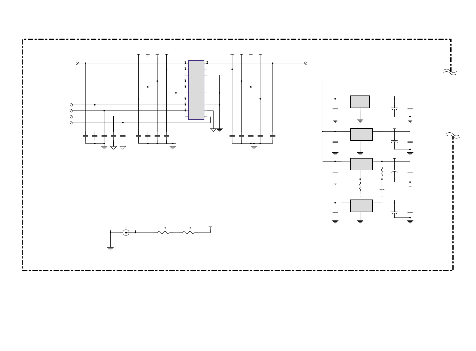
LCD03B
First issue 10 / 03
PC BOARD INTERFACE - INTERFACE PC BOARD - SCHALTBILD PC BOARD - SCHEMA DELLA PC BOARD INTERFAZ PC BOARD
( PC BOARD 7/7, 20”BI)
[P. 4]
LCD_ON
[P. 3]
PW R_ON
[P. 4]
MUTE
[P. 6]
AUDIO_L_O UT
[P. 6]
AU DIO_R_OUT
C140
220P J
C141
220P J
C142
220P J
C143
220P J
C144
220P J
C145
220P J
C146
220P J
C147
220P J
+12V +12V +5VS+5VSVCC VCC+19V
C148
220P J
TP 11 9
TP 12 1
TP 12 2
TP 12 3
TP 12 4
TP 12 5
TP 12 6
J11
12
34
56
78
910
11 12
13 14
15 16
17 18
19 20
2072060210
TP 12 0
(For EMI) (For EMI)
TP 23
J12
2
TP 24
1
3
OPEN
RT1
21
NC
RT2
t
21
NC
+12V
t
C149
220P J
C150
220P J
C151
220P J
+19V
C152
220P J
C153
220P J
LCD_BR
[P. 4]
+12V
+5VS
VCC
CHANGE C108 P/N to 79.4761D.3A1
23
23
+
23
20L0BI
PC BOA RD
48.M2305 .A00
R83
681F
C117
10U
16V
+9V
+
VCPU33
+
VCPU18
+
V33
+
C112
0.1U K
C115
0.1U K
C119
0.1U K
C109
0.33U Z
U15
1
VI
U16
U17
U18
VO
GND
780 9ABD2T
2
VOUTVIN
GND
LD1117-3. 3
1
VOUTVIN
GND
LM317 M
1
R84
301F
VOUTVIN
GND
LD1117-3. 3
1
3
C 108
47U
16V
C 111
47U
16V
C 114
47U
16V
C 118
47U
16V
C110
0.1U K
C113
0.1U K
C116
0.1U K
C120
0.1U K
Page 57

LCD03B
First issue 10 / 03
VIDEO SIGNAL PROCSSING - TRAITEMENT VIDEO - VIDEO SIGNALVERARBEITUNG - ELABORAZIONE VIDEO - TRATAMIENTO VIDEO
( VIDEO BOARD 1/6)
Opti cal Points
[P.3]
[P.3]
[P.3]
[P.3]
[P.3]
[P.3]
[P.2]
VCLK
VVS
VHS
VPEN
VF IELD
VY[0..7 ]
VU V[0..7]
+5VS +5VS
VC C
TP1
TP3
TP5
TP7
TP8 L27
TP10
VY0
VY1
TP12
VY2
TP14
TP16
VY3
VY4
TP19
VY5
TP21
TP22
VY6
TP24
VY7
TP27
VUV0
VUV1
TP28
TP30
VUV2
TP32
VUV3
VUV4
TP34
VUV5
TP36
TP38
VUV6
TP40
VUV7
TP97
TP43
TP44
TP45
1
3
5
7
9
11
13
15
17
19
21
23
25
27
29
31
33
35
37
39
41 42
43 44
45 46
47 48
49 50
51 52
53 54
55 56
57 58
59 60
J1
2
4
6
8
10
12
14
16
18
20
22
24
26
28
30
32
34
36
38
40
TP4
TP2
TP98
TP6
TP99
TP9
TP10 0
TP11
TP13
TP15
TP17
TP18
TP20
TP23
TP25
TP26
TP29
TP31
TP33
TP35
TP37
TP39
TP42
AV_DET
R1
0
TEKCON SLOT 60Pin
Screw Holes
L23
L24
L25
L26
L28
RI1
[P.4]
LI1
[P.4]
RI2
[P.4]
LI2
[P.4]
RI4
[P.4]
LI4
[P.4]
INPUT_DET
TV_DET
SD A
SCL
DECO E
TUNER _ACK
VIDEO_RESET
AV_SEL
CVBS_SE L
+12 V+12 V
VCC
+9 V+9 V
1000 OHM
1000 OHM
1000 OHM
1000 OHM
1000 OHM
1000 OHM
SD _Y_IN
SD_Y_ GND
SD_CB_I N
SD_CB_GND
SD_C R_IN
SD_ CR_GND
[P.4]
[P.2 .3]
[P.2 .3]
[P.2 .3]
[P.4]
[P.2 .3]
[P.4]
[P.2]
L22
[P.2]
[P.2]
[P.2]
[P.2]
[P.2]
[P.2]
BE AD
OP1
OP
OP
OP2
OP
OP9
OP
OP10
OP
OP
OP
OP5OP3
OPOP
OP1 2OP1 1OP8
OP
OP6OP4
OP
OP1 3
OP
OP7
OP
OP1 4
OP
5
4
3
2
H1
HOLE- V8
1
9
8
7
6
5
4
3
2
H2
HOLE-V8
1
9
8
7
6
5
4
3
2
H3
HOLE-V 8
1
9
8
7
6
5
4
3
2
H4
HOLE-V8
1
9
8
7
6
Page 58
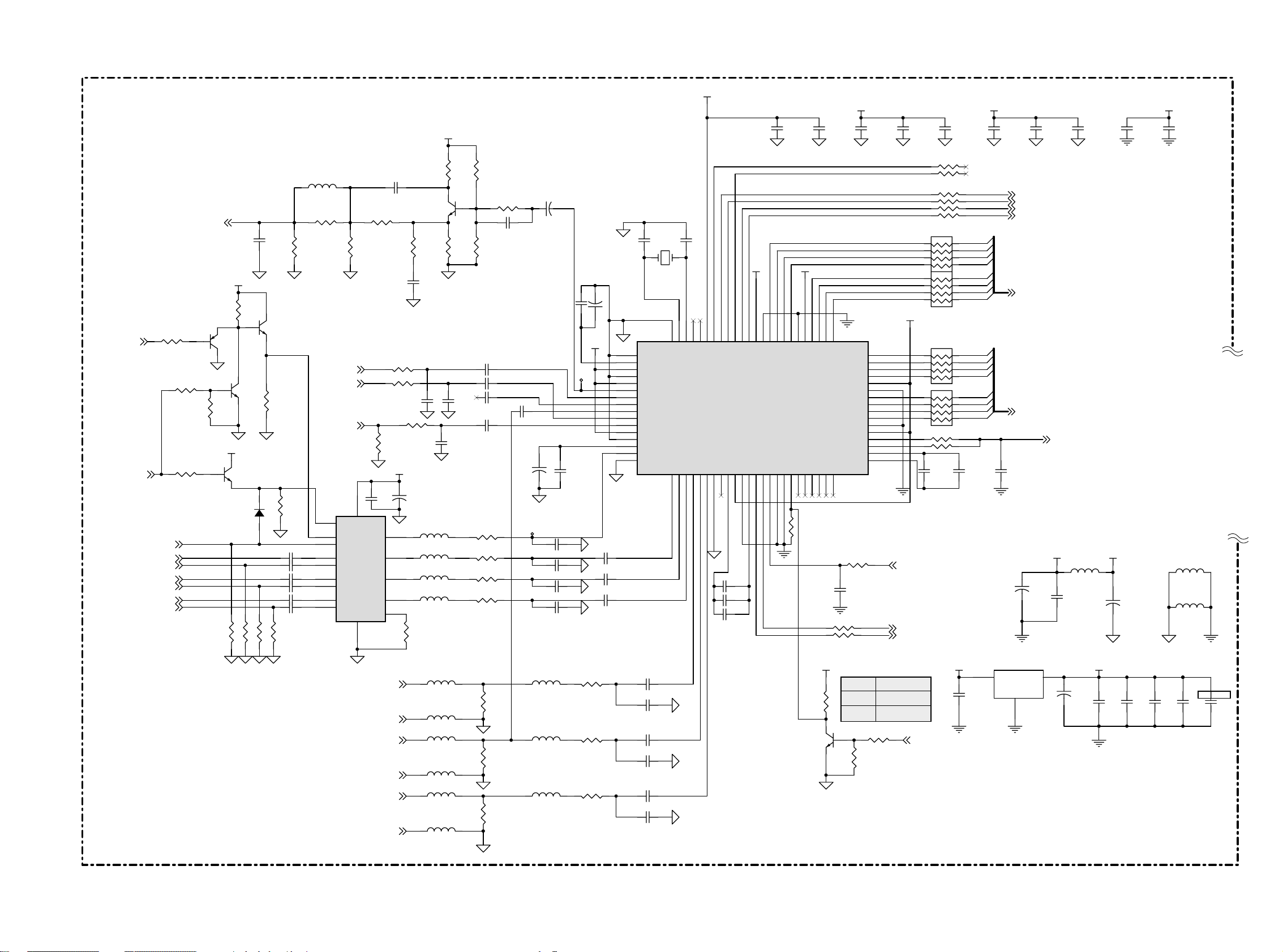
LCD03B
First issue 10 / 03
VIDEO SIGNAL PROCSSING - TRAITEMENT VIDEO - VIDEO SIGNALVERARBEITUNG - ELABORAZIONE VIDEO - TRATAMIENTO VIDEO
( VIDEO BOARD 2/6)
VCC_A
(Bypass Group Delay Circuit)
+9 V
PIN5 9 PIN5 2PIN6 9 P IN7 6
C1
0.1U K
C2
10U Z
C3
0.1U K
C4
1500P J
C5
390P K
C6
0.22U K
C7
1500P J
C8
390P K
C9
0.047U K
V33DVCC_ A VCC_A
C10
0.015U K
SCART_BLNK
[P.5]
SCA RT_FB_EN
[P.6]
[P.6]
[P.5]
[P.6]
[P.5]
[P.6]
[P.5]
[P.6]
[P.6]
TT_BLNK
SCART_BLUE
TEXT_ B
SCA RT_GREEN
TEXT_ G
SCAR T_RED
TEXT_ R
R262
100
R257
R260
CVB S_INPUT
1
10 K
0
1
VC C
R255
470
1
Q5
2N3906
32
32
Q8
1
2N3904
R258
10K
VCC
32
Q4
2N3904
D15
1N414 8
R1 8
R1 6
100
NC_R0 603
C11 9
OPE N
32
Q7
2N3904
R259
75
C 190 0.047U K
C 191 0.047U K
C 192 0.047U K
C 193 0.047U K
C 194 0.047U K
C 195 0.047U K
R22
R1 9
100
100
R261
150
L1
OPEN
R7 0
R7 8
OP E N
0
[P.4]
[P.4]
CVB S_VD
[P.4]
5
SEL
15 13
FBI 1 FBO
14
FBI 2
2
VIA1
6
VIA2
3
VIB1
7
VIB2
4
VIC1
8
VIC2
R64
R63
560
6.8K
C 255 180 P J
R6 8
270
R69
OPEN
R2 32
R11
NC_R0 603
+9 V
+
L35
L36
12
L37
11
L38
10
16
75
75
C26
10U
16V
L29
S_C
S_Y
R230
R231
C27
0.1U K
U3
VOA
VOB
VOC
IOCNR
GND VP
TDA8601T
91
SD_CB_I N
[P.1]
SD_CB_GN D
[P.1]
SD_Y_I N
L30
L31
[P.1]
SD_Y_ GND
[P.1]
SD_C R_IN
L32
L33
[P.1]
SD _CR_GND
L34
2N3904
R66
470
C2 54
82P J
C 184
330P J
0
3.3NH
3.3NH
3.3NH
3.3NH
R2
0
1000 OHM
1000 OHM
1000 OHM
1000 OHM
1000 OHM
1000 OHM
32
Q1
R62
470
C 185
330P J
C 186
68P J
R61
1
R65
3.3K
C13 0.68U K
C18 0.68U K
C14 OPE N
C19 0.68U K
R14
R226
R227
R228
C15 0.68U K
75
75
75
75
R2 3
75
R2 4
75
R2 5
75
2.2K
12
C 200
OPE N
TP47
L39
3.3NH
3.3NH
L40
L41
3.3NH
C45
+
22U
16V
12
C20
C21
+
0.047U K
10U
16V
C2 8 3 30P J
C3 6 3 30P J
C39 330P J
C41 330P J
[P.1]
C170.047U K
TP4 6
R233
R234
R235
3.3P C Y1
C16
+
10U
16V
12
VCC_ A
C34 0.22U K
C38 0.22U K
C40 0.22U K
65
66
67
68
69
70
71
72
73
74
75
76
77
78
79
80
75
75
75
C1 1
20.25MHZ
GNDF
VRT
I2CSEL
ISGND
VSUPF
VOUT
CI N
VIN1
VIN2
VIN3
VIN4
VSUPAI
GNDAI
VREF
FB1I N
AISGND
VPC3 23XD
VB1
VG1
VR1
C42 0.22U K
C4 3 3 30P J
C44 0.22U K
C1 18 330P J
C48 0.22U K
C5 4 3 30P J
C1 2
3.3P C
V3 3D V 33D
UV4
UV3
UV5
C3
C4C5C6
GNDC
VSUPC
UV0
UV1
UV2
6463626160595857565554535251504948474645444342
ASGF
XTAL2
XTAL1
N.C
CLK5
VSTBY
VS
MSY/HS
FPDAT/VSYA
FSY/HC/HSYA
AVO
INTLC
VSUPSY
C0C1C2
GNDSY
U1
VPC3230D
I2C : 0X 8E
B1/CB1I N
G1/Y1I N
R1/CR1I N
B2/CB2I N
G2/Y2I N
R2/CR2I N
ASGF
N.C/FFRSTWI N
VSUPCAP
VSUPD
GNDD
GNDCAP
SCL
SDA
RESQ
TEST
VGAV
YCOEQ
FFI E
FFW E
FFRSTW
FFRE
123456789
VB2
VG2
VR2
101112131415161718192021222324
R15
NC_R0 603
C30
0.22U K
C35
1500P J
C37
390P K
R3
1K
Q2
2N3904
R20
R21
VCC
UV6
UV7
41
C7
GNDLLC
VSUPLLC
VSUPPA
FFOE
CLK2 0
R7
10K
VSUPY
GNDY
LLC 1
LLC 2
GNDPA
R17
C33
100P K
DECOE
100
100
L
H
Y0
Y1
Y2
Y3
Y4
Y5
Y6
Y7
R5
40
39
38
37
36
35
34
33
32
31
30
29
28
27
26
25
100
Y/C Output
Disable
Enable
1K
R204
R205
R6
R8
R9
R10 NC_R0 603
5
6
7
8
5
6
7
8
V33D
RN3
Y0
5
Y1
6
Y2
7
Y3
8
RN4
Y4
5
Y5
6
Y6
7
Y7
8
R12
R13 NC_R 0603
VIDEO_RESET
[P.1]
SDA
[P.1]
SCL
DECOE
RN 1
47
RN 2
47
C22
1500P J
47
47
0
[P.1]
[P.1]
47
47
47
47
47
DU V0
4
DU V1
3
DU V2
2
DU V3
1
DU V4
4
DU V5
3
DU V6
2
DU V7
1
DY0
4
DY1
3
DY2
2
DY3
1
DY4
4
DY5
3
DY6
2
DY7
1
C23
0.1U K
C47
0.1U K
C25
O PEN
U4
LD1117-3. 3
1
SVVS
SVH S
SVPEN
VF IELD
DUV[ 0..7]
DY[ 0..7]
12
VOUTVI N
GND
[P.3]
[P.3]
[P.3]
[P.1]
[P.3]
[P.3]
SVCLK
VC C VCC_A
C29
+
47U
16V
23
C31
0.1U K
12
+
L2
BEAD
C46
47U
16V
[P.3]
V33DVC C
0.1U K
C49
L3
0.1U K
C51
PIN2 9
BE AD
L4
BE AD
PIN3 6
0.1U K
C5 2
0.1U K
C5 3
PIN4 5
12
C3 2
+
22U
16V
0.1U K
C50
PIN1 0
Page 59
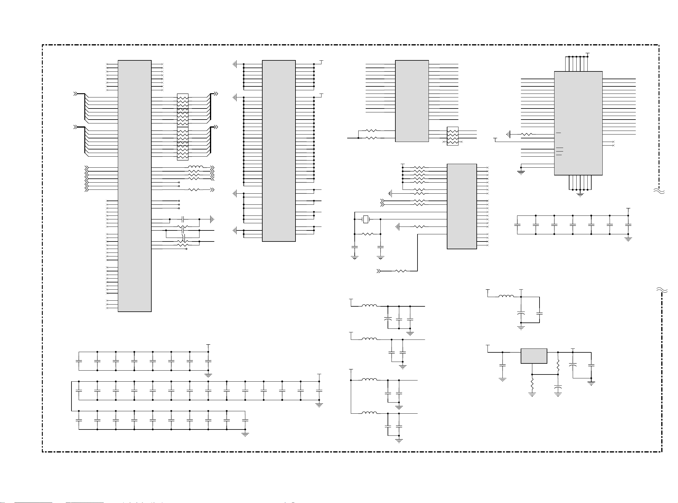
LCD03B
First issue 10 / 03
VIDEO SIGNAL PROCSSING - TRAITEMENT VIDEO - VIDEO SIGNALVERARBEITUNG - ELABORAZIONE VIDEO - TRATAMIENTO VIDEO
( VIDEO BOARD 3/6)
DY[0 ..7]
[P.2]
DUV[0 ..7]
[P.2]
[P.2]
[P.2]
[P.2]
[P.2]
[P.2]
[P.2]
[P.2]
SVHS
SVVS
SVCLK
SVCLK
SVPEN
SVVS
SVHS
C7 8
0.1U K
C8 8
0.1U K
C10 4
0.1U K
DY0
DY1
DY2
DY3
DY4
DY5
DY6
DY7
DU V0
DU V1
DU V2
DU V3
DU V4
DU V5
DU V6
DU V7
C7 9
0.1U K
C8 9
0.1U K
C10 5
0.1U K
100
43
VDDQ
6
P2P5V
VDDQ
VSSQ
12
+
VDDQ
VSSQ
0.1U K
2793
VDD
VDDQ
VSSQ
VSSQ
524612
C5 9
C72
47U
16V
P3P3 V
1
1428
VDDVSS
NC/RFU
41
VDD
VSS
51
DQ1 4
50
DQ1 3
48
DQ1 2
47
DQ1 1
45
DQ1 0
44
DQ9
42
DQ8
13
DQ7
11
DQ6
10
DQ5
8
DQ4
7
DQ3
5
DQ2
4
DQ1
2
DQ0
40
36
NC
VSS
54
HY57V641620HGT- 6
4M*16 SDRAM
C60
0.1U K
C76
0.1U K
C6 1
0.1U K
RAMD15
RAMD14
RAMD13
RAMD12
RAMD11
RAMD10
RA MD9
RA MD8
RA MD7
RA MD6
RA MD5
RA MD4
RA MD3
RA MD2
RA MD1
RA MD0
P3P3V
C6 2
0.1U K
112
134
187
219
251
105
115
126
137
147
171
189
193
202
212
222
228
233
240
246
253
196
198
148
164
167
152
155
158
C97
0.1U K
C1 13
0.1U K
19
49
77
10
24
39
46
57
65
74
85
96
59
61
U5B
Vs s
Vs s
Vs s
Vs s
Vs s
Vs s
Vs s
Vs s
PVs s
PVs s
PVs s
PVs s
PVs s
PVs s
PVs s
PVs s
PVs s
PVs s
PVs s
PVs s
PVs s
PVs s
PVs s
PVs s
PVs s
PVs s
PVs s
PVs s
PVs s
PVs s
PVs s
PVs s
PVs s
DPAVs s
DPDVs s
MPDVs s
MPAVs s
ADDVs s
ADAVs s
ADGVs s
AVS33B
AVS33G
AVS33R
C98
0.1U K
MPDVdd
MPAVd d
ADGVd d
AVD33G
PW1230
VDD1
VDD2
VDD3
VDD4
VDD5
VDD6
VDD7
VDD8
PVd d
PVd d
PVd d
PVd d
PVd d
PVd d
PVd d
PVd d
PVd d
PVd d
PVd d
PVd d
PVd d
PVd d
PVd d
PVd d
PVd d
PVd d
PVd d
PVd d
PVd d
PVd d
PVd d
PVd d
DPAVd d
DPDVd d
ADDVd d
ADAVd d
AVD33B
AVD33R
C99
0.1U K
5
34
93
123
140
175
205
235
14
29
42
54
64
69
80
90
101
109
120
131
143
165
180
200
208
216
224
230
237
243
249
256
197
199
58
60
149
163
166
151
154
157
AVDD2
AVDD1
A VD25
A VD33
C1 00
0.1U K
P2P5 V
P3P3 V
P3P3 V
C1 01
0.1U K
[P.1]
R26
RC LK
R28
[P.1]
[P.1]
Y2 1 0MHZ
R45
C65
18P J
VIDEO_RESET
P2P5 V
P3P3 V
P2P5 V
RAMA0
RAMA1
RAMA2
RAMA3
RAMA4
RAMA5
RAMA6
RAMA7
RAMA8
RAMA9
RAMA1 0
RAMA1 1
RAMA1 2
RAMA1 3
L6
42 OHM
L7
42 OHM
L8
42 OHM
L9
42 OHM
SCL
SDA
2M
0.1U K
0.1U K
0.1U K
C86
C1 02
0
0
C66
18P J
C73
213
210
207
204
203
206
209
211
214
217
215
220
221
218
223
229
12
C69
22U
16V
U5C
MA0
MA1
MA2
MA3
MA4
MA5
MA6
MA7
MA8
MA9
MA1 0
MA1 1
MA1 2
MA1 3
MCLKFB
MCLK
P3P3V
0
C70
+
0.1U K
C87
0.01U K
C 103
0.01U K
PW1230
R30
R32
R34
R36
R37
R39
R40
R41
R42
R44
R4 8
C71
0.01U K
C74
0.01U K
AVDD2
AVDD1
MD10
MD11
MD12
MD13
MD14
MD15
mRASn
mCASn
mWEn
DI _RESET
A VD25
A VD33
MD0
MD1
MD2
MD3
MD4
MD5
MD6
MD7
MD8
MD9
10K
10K
10K
10K
10K
0
0
R AMD0
255
R AMD1
252
R AMD2
248
R AMD3
245
R AMD4
242
R AMD5
239
R AMD6
236
R AMD7
232
R AMD8
231
R AMD9
234
RAMD10
238
RAMD11
241
RAMD12
244
RAMD13
247
RAMD14
250
RAMD15
254
33
RN 8
U5D
TDO
TCK
TDI
TMS
TRSTN
I2CA1
I2CA2
SCL
SDA
XTAL I
XTAL O
TEST
RESETn
5
6
7
8
MCUWR
MCUCMD
MCURDY
PW1230
R RASn
R CASn
RWEn
MCUA0
MCUA1
MCUA2
MCUA3
MCUA4
MCUA5
MCUA6
MCUA7
MCUD0
MCUD1
MCUD2
MCUD3
MCUD4
MCUD5
MCUD6
MCUD7
MCUCS
168
169
170
172
173
174
176
177
178
179
181
182
183
184
185
186
190
191
192
188
P3P3V
4
225
3
226
2
227
1
48
50
51
52
53
0
43
0
44
45
47
40
41
0
56
55
R27
RAMA11
RAMA10
RAMA9
RAMA8
RAMA7
RAMA6
RAMA5
RAMA4
RAMA3
RAMA2
RAMA1
RAMA0
RAMA12
RAMA13
RC LK
P3P3V
R RASn
R CASn
RWEn
C56
0.1U K
1K
C57
0.1U K
49
U6
35 53
A1 1 DQ1 5
22
A1 0
34
A9
33
A8
32
A7
31
A6
30
A5
29
A4
26
A3
25
A2
24
A1
23
A0
20
BA0
21
BA1
19
CS
38
CL K
37
CKE
18
RAS
17
CAS
16
WE
39
UDQM
15
LDQM
C58
0.1U K
I2C : 0X64
C7 5
0.1U K
P3P3V
12
U7
C67
+
10U
16V
LM317 M
1
GND
VOUTVI N
R50
681F
C68
0.1U K
23
R49
681F
12
C77
+
10U
16V
V33D
VC C
L5
42 OHM
U5 A
1
VB0
2
VB1
3
VB2
4
VB3
6
VB4
7
VB5
8
VB6
9
VB7
15
VG0
16
VG1
17
VG2
18
VG3
20
VG4
21
VG5
22
VG6
23
VG7
30
VR0
31
VR1
32
VR2
33
VR3
35
VR4
36
VR5
37
VR6
38
VR7
11
SVHS
12
SVVS
13
SVCLK
25
PVCLK
26
CREF
27
PVVS
28
PVHS
70
DGB0
71
DGB1
72
DGB2
73
DGB3
75
DGB4
76
DGB5
78
DGB6
DGB7
DGG0
DGG1
DGG2
DGG3
DGG4
DGG5
DGG6
DGG7
DGR0
DGR1
DGR2
DGR3
DGR4
DGR5
DGR6
DGR7
DGHS
DGVS
DGCL K
PW1230
C8 0
0.1U K
C9 0
0.1U K
C10 6
0.1U K
VREFOUT
TESTCL K
79
81
82
83
84
86
87
88
89
91
92
94
95
97
98
99
66
67
68
DB0
DB1
DB2
DB3
DB4
DB5
DB6
DB7
DG0
DG1
DG2
DG3
DG4
DG5
DG6
DG7
DR0
DR1
DR2
DR3
DR4
DR5
DR6
DR7
DCL K
DVS
DHS
DEN
DENG
DENB
DENR
ADR
ADG
ADB
VREFI N
RSET
COMP
MVE
CGMS
C81
0.1U K
C91
0.1U K
C1 07
0.1U K
110
111
113
114
116
117
118
119
DG0
121
DG1
122
DG2
124
DG3
125
DG4
127
DG5
128
DG6
129
DG7
130
DR0
132
DR1
133
DR2
135
DR3
136
DR4
138
DR5
139
DR6
141
DR7
142
DC LK
102
DVS
103
DHS
104
DE N
145
106
107
DP EN
108
156
153
150
161
162
R4 3
159
C63 0.01U K
160
C64 10U
R4 6
201
R4 7
146
144
C8 2
0.1U K
C9 2
0.1U K
C10 8
0.1U K
47
4
3
2
5
RN
1
4
47
3
2
RN 6
1
4
47
3
2
RN 7
1
4
47
3
2
RN 9
1
70
R29
R31
R33
R35
TP4 8
TP4 9
R38
TP5 0
TP5 1
TP5 2
C55 0.01U K
270
+
TP5 3
C83
0.1U K
C93
0.1U K
C1 09
0.1U K
5
6
7
8
5
6
7
8
5
6
7
8
5
6
7
8
OHM
12
0
0
VY 0
VY 1
VY 2
VY 3
VY 4
VY 5
VY 6
VY 7
V UV0
V UV1
V UV2
V UV3
V UV4
V UV5
V UV6
V UV7
47
47
47
47
16V
C8 4
0.1U K
C9 4
0.1U K
C1 10
0.1U K
A VD33
P3P3 V
P2P5 V
[P.1]
C8 5
0.1U K
C9 5
0.1U K
C1 11
0.1U K
VY[0..7 ]
VUV[0..7]
[P.1]
VCLK
VVS
VHS
DECOE
VPEN
[P.1]
[P.1]
[P.1]
[P.1]
[P.1]
C96
0.1U K
C11 2
0.1U K
Page 60

LCD03B
First issue 10 / 03
VIDEO SIGNAL PROCSSING - TRAITEMENT VIDEO - VIDEO SIGNALVERARBEITUNG - ELABORAZIONE VIDEO - TRATAMIENTO VIDEO
( VIDEO BOARD 4/6)
VC C
C 114
R51
0.1U K
68K
R53
68K
Q305
2N3904
Q6
2N3904
R52
100
R55
3
2N3904
2N3906
R311
R77
Q3
2N3904
0
C 115
10U
16V
CV BS
VIDEO_I N
VCC
+
C1 16
0.1U K
1K
R54
[P.4]
21
0
0
S_Y
S_C
[P.2]
[P.2]
Bottom View
354
Bottom View
G1
1
G2
2
G3
TP54
J6
56
56
34
34
TP5 5
TP5 6
CVBS_ IN
R5 6
1K
1000 OHM
L10
C1 17 10U
+
+5VS
16V
[P.1]
LI1
6
12
12
TP5 7
R5 7
1K
R58
22K
R59
22 K
D1
TZMC5V1
D2
TZMC5V1
75
R60
DN 1
BAV99
RI1
[P.1]
21
+5VS
+5VS
TZMC5V1
D4
0.1U K
+ +
16V
DN 2
BAV99
16V
DN 3
BAV99
0.1U K
C1 89
C1 22
VC C
VC C
R3 16
68K
R3 17
68K
R72
68K
R76
68K
R319
R80
R3 18
100
R74
100
1K
1K
TZM C5V1
D3
J7
3
Y
1
TP41
S1
S1
3
4
221 028900 1
.
G1
.
C
INPUT_DET
G1
2
4
TP58
TP59
L12
1000 OHM
L1
1
C 127
O PEN
1000
C 128
O PEN
C1 20 10U
R71
75
OHM
C1 24 10U
R82
75
74
U2C
5
3
HC405
16
[P.1]
4
AV_SEL
LOW
HIGH
AV_SEL
CVB S_VD
OUTPUT
CVBS
TV
[P.2]
9
3
876
14
13
+9 V
TP6 4
SCL
[P.1]
SDA
[P.1]
Top View (ST)
TP6 1
1
3
5
7
9
11
13
1
2
1
BSN2 0
Q13
2
BSN 20
Q1 1
3
VCC
C 130
100
16V
R249
C 198
OPE N
0.1U K
+9V
22
2
1
J8
2
4
6
8
10
12
14
Q1 0
3
3
BSN2 0
3
TP62
TP63
TP65
TP66
TP67
TP68
TP69
1
2
Q1 2
BSN 20
L13
1000 OHM
R89
R91
R73 NC_R0 603
SCL_TV
SDA_TV
VC CV33D
R1083.3K
R1073.3K
1
2
100
100
+9V
[P.6]
42 OHM
L20
TUNER_DET
TUNE R_ACK
+
R253
C 125
10U
16V
C 196
O PEN
560
C 133 10U
R254
470
R98
Q2 3
2N3906
R1
09
R1
10
C 197
O PEN
+
470
470
R94
68K
+
Q2 2
2N3904
R2 50
1K
SCART_ROUT
SCART_L OUT
C 199
OPE N
R8 8
68K
R9 0
100
R9 7
C 126
10U
16V
RI2
LI2
[P.1]
[P.1]
[P.5]
[P.5]
1K
R92
Q9
2N3904
68
R95
[P.5]
VIDEO_OUT
[P.5]
[P.1]
CVBS_ SEL
0
SCART_CVBS
11
16
TV
12
U2A
74HC4053
876
14
CVBS_SEL Output
13
LOW
VIDEO_I N
[P.4]
CVBS_VD
SCART_CVBSHIGH
Page 61

LCD03B
First issue 10 / 03
VIDEO SIGNAL PROCSSING - TRAITEMENT VIDEO - VIDEO SIGNALVERARBEITUNG - ELABORAZIONE VIDEO - TRATAMIENTO VIDEO
( VIDEO BOARD 5/6)
[P.4]
SCART_ROUT
SCART_L OUT
[P.4]
D5
TZM C5V1
D7
TZMC5V1
R163
R164
D6
TZM C5V1
D8
TZMC5V1
0
0
R19 4
100K
R195
C 141
100K
SCAR T_BLUE_I N
1000P J
1000P J
[P.5]
SCART_G REEN_I N
[P.5]
SCART_RE D_I N
[P.5]
L15
1000 OHM
C1 42
TP70
TP72
TP75
TP78
TP80
TP82
DN 8
BAV9 9
11
13
15
17
19
21
+5VS
+5VS
DN 6
BAV99
L14
1000 OHM
R1 19
R1 20
R121
22K
SCAR T_BLUE_I N
R115
75
1K
1K
R1 22
22K
[P.5]
[P.5]
[P.5]
[P.2]
SCAR T_CVBS_I N
[P.5]
SC ART_AL_I N
[P.5]
SCART _AR_I N
[P.5]
J9
1
3
5
7
9
2
4
6
8
10
12
14
16
18
20
TP71
TP7 3
TP74
TP76
CLK_OUT
DAT A_OUT
TP81
TP83
0
R165
R166
0
R167
0
TP7 7
TP7 9
R168
0
SCART _CVBS_I N
[P.5]
SCART_ AR_I N
SCA RT_AL_I N
D13
12.4~14 .1V
R125
D1 4TZMC5V1
75
SCA RT_SWITCH
SCART_BLNK
[P.5]
VIDEO_OUT
+
C1 43 10U
1000 OHM
L16
16V
D9 TZMC5V1
D11 TZMC5V1
R126
75
D10 TZMC5V1
D12 TZMC5V1
+
C 145 10U
C 140
0.1U K
BAV99
16V
DN 9
VC C
+5VS
R1 13
68K
R1 17
68K
R114
100
R118
C 154
O PEN
1K
LI4
RI4
[P.1]
[P.1]
Q1 4
2N390 4
R116
SCART_BLUE
47
SCART_CVBS
[P.2]
[P.2]
[P.4]
+5VS
DN 10
BAV99
SCA RT_SWITCH
[P.5]
R21 5
10K
8.6- 12V
3.5- 8.6V
0-3 .5V
0V~4. 85V
R245
6.8K
Mode1
Mode2
0
1
0
0
11
+5VS
R217
R21 6
4.3K
10K
R21 8
R219
10K
3.9K
Auto
16:9
Manual
3.49V
1.40V
C 155
1000 OHM
[P.5]
SCART_GREEN_I N
+5VS
R224
10K
4
U15
OUT1
OUT2
OUT3
OUT4
11
1
7
8
14
GND V+
LMV3 24M
3
IN1+
2
IN1-
5
IN2+
6
IN2-
10
IN3+
9
IN3-
12
IN4+
13
IN4-
R22 0
R22 1
100K
100K
R222
NC_R0 603
R2 23
NC_R0 603
Q1
2N3904
R2 25
10K
Q16
2N3904
R1 27
High Active
0
SCART_M ODE1
SCART_M ODE2
TV_DET
SCART_RE D_I N
[P.5]
[P.6]
[P.6]
[P.1]
L17
1000 OHM
L18
C 147 10U
R132
75
C 149 10U
R138
75
16V
+5VS
DN 11
BAV99
++
16V
O PEN
C 156
O PEN
SCA RT_GREEN
SCAR T_RED
[P.2]
[P.2]
Page 62

LCD03B
First issue 10 / 03
VIDEO SIGNAL PROCSSING - TRAITEMENT VIDEO - VIDEO SIGNALVERARBEITUNG - ELABORAZIONE VIDEO - TRATAMIENTO VIDEO
( VIDEO BOARD 6/6)
+2.5V
[P.4]
+3.3VDAC
C 167
0.1U K
U1 3
1
NC
2
NC
3
NC
45
GND SDA
VCC
WP
SCL
8
7
6
EE_SDA
AT24 C02
CVBS _INPUT
[P.1]
[P.1]
SCL
SDA
R243
R244
R171
4.7K
EE_SCL
C 172 0.1U K
R181
NC_R0 603
0
0
R1 72
4.7K
R2 39
R2 40
0
0
C 168
0.1U K
+2.5VDAC +2.5VDAC
C 169
0.1U K
TP8 4
+3.3VDAC
TT_STAR T
U14
1
P0.0
2
P0.1
3
P0.2
4
P0.3
5
P0.4
6
P0.5
7
P0.6
8
P0.7
9
VDD 2.5
10
VSS
11
VDD 3.3
12
CVBS
13
VDDA 2. 5
14
VSSA
15
P2.0
16
P2.1
17
P2.2
18
P2.3
19
HS/SSC
20
VS
21
P3.0
22
P3.1
23
P3.2
24
P3.3
25
P3.4
26 27
P3.5 P3.6
SDA555 xFL
VDD 3. 3
VDD 2. 5
BLANK/COR
VDDA 2. 5
VSSA
XTAL 1
XTAL 2
RST-
VDD 3. 3
P1.7
P1.6
P1.5
P1.4
P1.3
P1.2
P1.1
P1.0
VSS
P4.3
P4.2
VSS
P3.7
B
G
R
52
51
50
49
48
47
46
45
44
43
42
41
40
39
38
37
36
35
34
33
32
31
30
29
28
I2C : 0X60
+3.3VDAC
TT_FSB
TT _B
TT _G
TT_ R
TT_ RSTn
R25 2
0
R23 6
C 170
0.1U K
NC_R0 603
+2.5V
+3.3V
C 171
0.1U K
R1 79
R1 80
R1 82
R1 83
R184
10K
C 176
+
10U
16V
R189
0
[P.6]
LANG3
[P.6]
LANG2
[P.6]
R191
R190NC_R 0603
R193
R192NC_R 0603
0
0
LANG3
LANG2
LANG1
C 177
33P J
Y3
6MHZ
FSB
BLUE
GREEN
RE D
C1 78
33P J
0
0
0
0
LANG1
LCB
INFO
LIS T
I2C_EN
RGB_G AIN
R174 NC_R 0603
R175
R176 NC_R 0603
R177
R178 NC_R 0603
0
0
BLUE
GREEN
RE D
+3.3VDAC
R143
220
Q18
2N3904
R1 49
330
R14 4
68
2N390 6
Q2 1
+3.3V
R1 45
68
2N3906
Q2 0
R1 46
68
2N3906
Q19
R14 8
R15 0
R15 1
R15 2
47
TT_BLNK
10
TEXT_ B
10
TEXT_ G
10
TEXT_R
[P.2]
[P.2]
[P.2]
[P.2]
[P.2]
[P.2]
C1 51
0.1U K
SVVS
SVHS
LD1117-3. 3
C1 64
0.1U K
U9
U1 2
R185
R186
VOUTVIN
GND
1
VOUTVIN
GND
LM317 M
1
R1 70
681F
+3.3VDAC
R1 59
0
0
[P.1]
[P.1]
+
+
R169
681F
C 150
47U
16V
C 166
10U
16V
+3.3VDAC +3.3VVCC
+2.5VDAC +2.5VVCC
+
23
23
C 152
0.1U K
C 162
47U
16V
L19
BE AD
L21
C1 65
0.1U K
BE AD
SDA
C1 53
+
10U
16V
C1 63
+
10U
16V
R157
3.3K
R160
NC_R 0603
R1 58
R1 61
3.3K
C 161
0.1U K
U11
16
NC_R0 603
NC_R0 603
R1 62
14
15
13
1
2
3
VDD
SCL
SDA
INT
A0
A1
A2
PCA9554P
GND
W
P0 0
P0 1
P0 2
P0 3
P0 4
P0 5
P0 6
P0 7
4
5
6
7
9
10
11
12
8
I2C : 0X48
3.3K
SCA RT_FB_EN
LANG1
LANG2
LANG3SCL
SCA RT_FB_EN
TUNER_DET
SCART_M ODE1
SCART_M ODE2
[P.6]
[P.6]
[P.6]
[P.2]
[P.4]
[P.5]
[P.5]
+3.3VDAC
PIN1 1 P IN30 PIN4 4
C17 3
0.1U K
C17 4
0.1U K
C1 75
0.1U K
Page 63
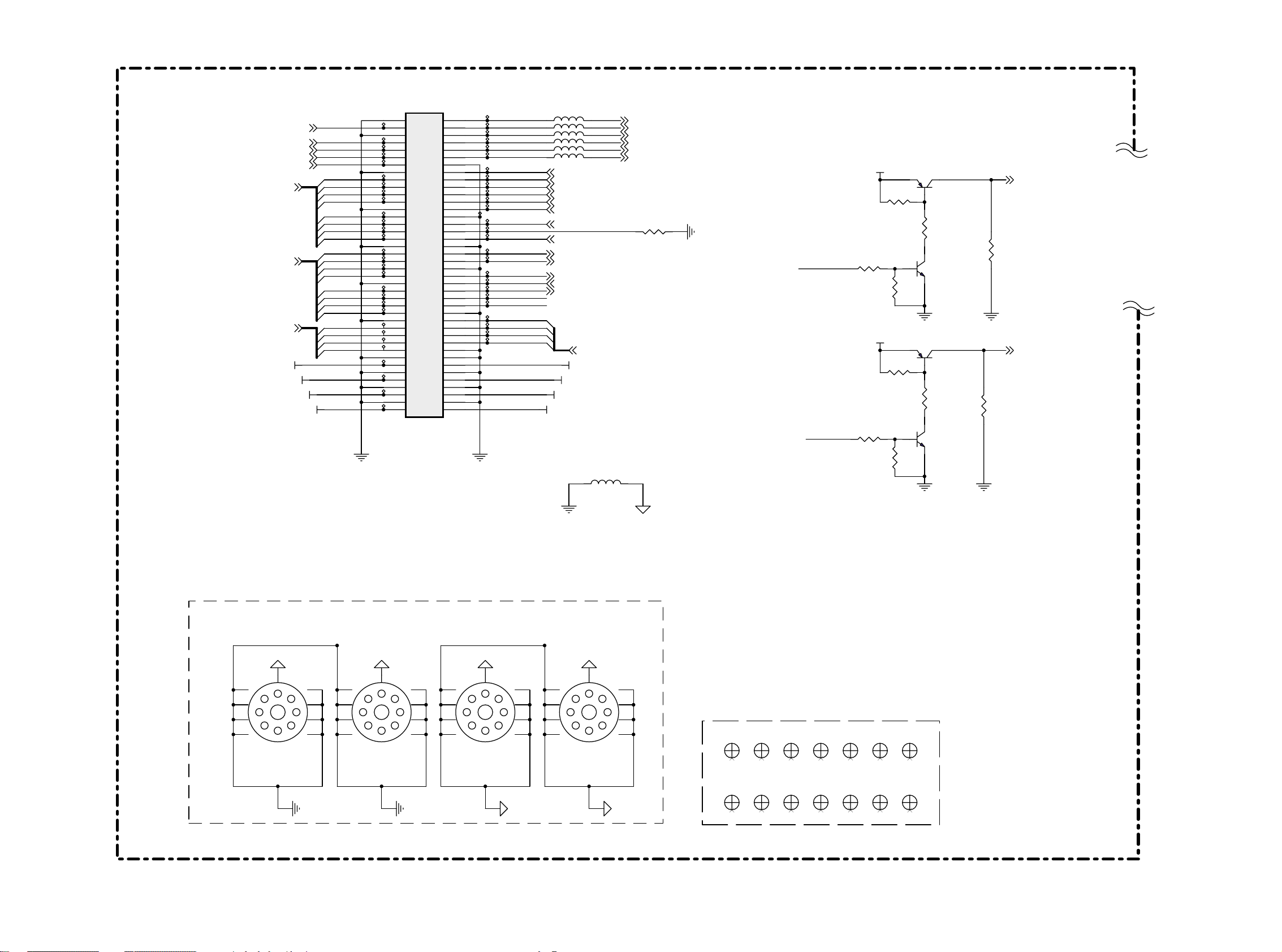
LCD03B
First issue 10 / 03
VIDEO SIGNAL PROCSSING - TRAITEMENT VIDEO - VIDEO SIGNALVERARBEITUNG - ELABORAZIONE VIDEO - TRATAMIENTO VIDEO
( VIDEO BOARD 1/6, 20”BI)
[P. 3]
[P. 3]
[P. 3]
[P. 3]
[P. 2]
[P. 3]
[P. 3]
[P. 3]
GY[0.. 7]
BU [0..7]
RV [0..7]
+12V
+5VS
VCL K
VVS
VH S
VPEN
VFI ELD
VCC
+9V
J1
TP 1
TP 3
TP 5 TP 9
TP 7
TP 8
GY 0
TP 10
GY 1
TP 12
GY 2
TP 14
GY 3
TP 16
GY 4
TP 19
GY 5
TP 21
GY 6
TP 22
GY 7
TP 24
BU 0
TP 27
BU 1
TP 28
BU 2 AV_ SEL_I N
TP 30
BU 3
TP 32
BU 4
TP 34
BU 5
TP 36
BU 6
TP 38
BU 7
TP 40
RV 0
TP 10 1
RV 1
TP 10 2
RV 2
TP 10 3
RV 3
TP 10 4
TP 97
TP 43
TP 44
TP 45
1
3
5
7
9
11
13
15
17
19
21
23
25
27
29
31
33
35
37
39
41
43
45
47
49
51
53
55
57
59
61
63
65
67
69
71
73
75
77
79
2050044080
2
4
6
8
10
12
14
16
18
20
22
24
26
28
30
32
34
36
38
40
42
44
46
48
50
52
54
56
58
60
62
64
66
68
70
72
74
76
78
80
TEKCON SLOT 80Pin
TP 4
TP 2
TP 98
TP 6
TP 99
TP 10 0
TP 11
TP 13
TP 15
TP 17
TP 18
TP 20
TP 23
TP 25
TP 26
TP 29
TP 31
TP 33
TP 35
TP 37
TP 39
TP 42
TP 10 5
TP 10 6
TP 10 7
TP 10 8
L23
L24
L25
L26
L27
L28
AV_ DET
AV_ SEL_I N
YC _SEL_I N
RV 4
RV 5
RV 6
RV 7
1000 OHM
1000 OHM
1000 OHM
1000 OHM
1000 OHM
1000 OHM
[P. 4]
RI1
[P. 4]
LI1
[P. 4]
RI2
[P. 4]
LI2
[P. 5]
RI4
[P. 5]
LI4
INPUT_D ET
[P. 4]
TV_DET
SDA
SC L
[P .2.3]
DEC OE
TUNER_ACK
VIDE O_RESET
RV [0..7]
+12V
+5VS
VCC
+9V
L22
SD_Y_I N
SD_Y_ GN D
SD_CB _IN
SD_CB _GND
SD_ CR_IN
SD _CR_GND
[P. 2]
[P .2.3]
[P .2.3]
R1
(old net: TT_ST ART)
[P .2.3]
[P. 3]
BEAD
[P. 2]
[P. 2]
[P. 2]
[P. 2]
[P. 2]
[P. 2]
0
[P. 4]
YC _SEL_I N
R321
1K
R197
1K
+9V
+9V
R320
10K
R195
10K
1
R194
10K
1
R198
10K
Q26
2N3906
Q24
2N3906
1
R322
1K
32
Q17
2N3904
1
R196
1K
32
Q25
2N3904
32
32
R335
10K
AV_SEL
R334
10K
CVBS_SEL
[P. 4]
[P. 2]
Screw Holes
5
4
3
2
H1
HO LE-V 8
20L0BI
VIDEO BOARD
48.M2306 .A00
1
9
8
7
6
5
4
3
2
H2
HO LE-V 8
1
9
8
7
6
5
4
3
2
H3
HO LE-V 8
1
9
8
7
6
5
4
3
2
H4
HO LE-V 8
1
9
8
7
6
Optical Points
OP1
OP
OP
OP2
OP
OP9
OP
OP
OP10
OP
OP6OP4
OP
OP13
OP
OP7
OP
OP14
OP
OP5OP3
OP
OP
OP12OP11OP8
OP
OP
Page 64

LCD03B
First issue 10 / 03
VIDEO SIGNAL PROCSSING - TRAITEMENT VIDEO - VIDEO SIGNALVERARBEITUNG - ELABORAZIONE VIDEO - TRATAMIENTO VIDEO
( VIDEO BOARD 2/6, 20”BI)
[P. 5]
SCART _BLN K
SCART _F B_EN
[P. 6]
[P. 5]
[P. 6]
[P. 5]
[P. 6]
[P. 5]
[P. 6]
[P. 6]
R343
NC_R0603
R338
0
TT_BLNK
SCART _BLU E
TEX T_ B
SCART_GREEN
TEX T_ G
SC ART_ RED
TE XT _ R
R340
Q27
CVBS_INPU T
VCC
R342
47 0
Q30
2N3906
10K
VCC
2N3904
D15
R16
Q28
R339
10K
1N4148
R18
10 0
NC_R0603
R19
10 0
C119
Q29
R341
2N3904
R337
15 0
R22
10 0
R330
NC_C0603
2N3904
75
15 13
14
C1931U Z
C1941U Z
C1951U Z
C1961U Z
C1971U Z
C1981U Z
VCC
R63
R331
47 0
C191
82P J
Q1
2N3904
27 0
56 0
R62
47 0
75
75
L1
R70
NC_R0603
NC _L1206
R69
[P. 4]
S_C
S_Y
0
NC_R0603
C199 180P J
R68
R230
R231
[P. 4]
[P. 4]
CVBS_V D
5
2
6
3
7
4
8
U3
SEL
FBI 1 FBO
FBI 2
VOA
VIA1
VIA2
VOB
VIB1
VIB2
VOC
VIC1
VIC2
IOCNR
GND VP
TDA8601T
91
C2 7
0.1U K
12
11
10
16
R2
0
R232
R11
NC _R0603
+9V
+
C2 6
10U
16V
SD_CB _IN
[P. 1]
L35
3.3NH
L36
3.3NH
L37
3.3NH
L38
3.3NH
L29
[P. 1]
SD_CB _GND
SD_Y_I N
[P. 1]
[P. 1]
SD_Y_ GN D
[P. 1]
SD_ CR_I N
[P. 1]
SD _CR_GND
C184
330P J
0
1000 OHM
1000 OHM
L30
1000 OHM
L31
1000 OHM
L32
1000 OHM
L33
1000 OHM
L34
R64
6.8K
R65
3.3K
C 186
68P J
R14
R227
R228
R336
C200
2.2K
NC_C0603
C1 3 0 .68U K
C1 8 0 .68U K
C185
330P J
C1 9 0 .68U K
75
75
75
75
R23
75
R24
75
R25
75
C4 5
22U
16V
C2 0
10U
16V
TP 47
C2 8 330P J
C3 6 330P J
C3 9 330P J
C4 1 330P J
3.3NH
L39
L40
L41
+
C1 5 0 .68U K
+
C2 1
0.047U K
3.3NH
3.3NH
C1 70.047U K
+
VC C_ A
TP 46
C3 4 0 .22U KR226
C3 8 0 .22U K
C4 0 0 .22U K
R233
R234
R235
C1 6
10U
16V
C1 1
3.3P C
65
GNDF
66
VRT
67
I2CSEL
68
ISGND
69
VSUPF
70
VOUT
71
CI N
72
VIN1
73
VIN2
74
VIN3
75
VIN4
76
VSUPAI
77
GNDAI
78
VREF
79
FB1I N
80
AISGND
VPC 323XD
C4 2 0 .22U K
75
C4 3 330P J
C4 4 0 .22U K
75
C118 330P J
75
C4 8 0 .22U K
C5 4 330P J
Y1
20.25 MHZ
64
63
ASG F
B1/CB1I N
123456789
VB1
VG1
VR 1
VCC _A
C1 2
3.3P C
62616059585756
N.C
CLK 5
XTAL 2
XTAL 1
VSTBY
FPDAT/VSYA
VPC3230D
G1/Y1I N
R1/CR1I N
B2/CB2I N
G2/Y2I N
R2/CR2I N
ASG F
VB2
VG2
VR 2
PIN5 9 PIN52PIN69 PIN76
C1
0.1U K
V33 D V33 D
UV 4
UV 3
UV 2
47464544434241
C3
GNDC
VSUPC
55
VS
MSY/H S
FSY/HC/HSYA
54
53
AVO
UV 0
5251504948
C0C1C2
INTLC
GNDS Y
VSUPSY
UV 1
U1
I2C : 0X8E
N.C/FFRSTWI N
VSUPCAP
VSUPD
GNDD
GNDCA P
SC L
SD A
RESQ
TEST
VGAV
YCOE Q
FFI E
FFWE
101112131415161718192021222324
R15
NC _R0603
C3 0
0.22U K
C3 5
1500 P J
C3 7
390P K
R3
1K
2N3904
C2
10U Z
UV 5
UV 7
UV 6
C4C5C6
C7
VSUPY
GNDY
GNDLLC
VSUPLLC
VSUPPA
GNDPA
FFRSTW
FFR E
FFOE
CLK20
R17
R20
R21
VCC
DECO EY/C Output
Q2
R7
10K
Y0
Y1
Y2
Y3
Y4
Y5
Y6
Y7
LLC1
LLC2
C3 3
100P K
10 0
10 0
L
H
R5
C3
0.1U K
10 0
Y0
40
Y1
39
Y2
38
Y3
37
36
35
Y4
34
Y5
33
Y6
32
Y7
31
30
29
28
27
26
25
Disable
Enabl e
1K
VIDEO BOARD
C4
1500 P J
R204
R205
R6
R8
R9
R1 0 NC_R0603
RN1
47
5
6
7
8
5
6
7
8
RN2
V33 D
47
RN3
5
6
7
8
RN4
5
6
7
8
R12
R1 3 NC_R0603
C2 2
1500 P J
VIDE O_RESET
[P. 1]
SDA
[P. 1]
SC L
DEC OE
20L0BI
48.M2306 .A00
C5
390P K
4
3
2
1
4
3
2
1
47
4
3
2
1
47
4
3
2
1
0
[P. 1]
[P. 1]
47
47
47
47
47
DU V0
DU V1
DU V2
DU V3
DU V4
DU V5
DU V6
DU V7
DY0
DY1
DY2
DY3
DY4
DY5
DY6
DY7
C2 3
0.1U K
C4 7
0.1U K
U4
C6
0.22U K
C2 5
22P J
1
SVVS
SVHS
SVPE N
VFIELD
DUV [0..7]
DY[0..7 ]
+
C2 9
47U
16V
VOUTVI N
GND
LD1117-3. 3
C7
1500 P J
[P. 3]
[P. 3]
[P. 3]
[P. 1]
C8
390P K
[P. 3]
[P. 3]
[P .3 ]
SVC LK
VCC VC C_ A
L2
BEAD
C3 1
0.1U K
23
V33 DVCC
+
C4 6
0.1U K
47U
16V
C4 9
V33 DVC C_ A VC C_ A
0.1U K
C5 1
PIN2 9
C1 0
0.015U K
L3
BEAD
L4
BEAD
0.1U K
C5 2
PIN3 6
0.1U K
C5 3
PIN4 5
C9
0.047U K
C3 2
+
22U
16V
0.1U K
C5 0
PIN1 0
Page 65

LCD03B
First issue 10 / 03
VIDEO SIGNAL PROCSSING - TRAITEMENT VIDEO - VIDEO SIGNALVERARBEITUNG - ELABORAZIONE VIDEO - TRATAMIENTO VIDEO
( VIDEO BOARD 3/6, 20”BI)
DY[0..7 ]
[P. 2]
DU V[0..7]
[P. 2]
[P. 2]
[P. 2]
[P. 2]
[P. 2]
[P. 2]
[P. 2]
[P. 2]
SVHS
SVVS
SVC LK
SVC LK
SVPE N
SVVS
SVHS
C7 8
0.1U K
C8 8
0.1U K
C 104
0.1U K
C7 9
0.1U K
C8 9
0.1U K
C 105
0.1U K
DY0
DY1
DY2
DY3
DY4
DY5
DY6
DY7
DU V0
DU V1
DU V2
DU V3
DU V4
DU V5
DU V6
DU V7
100
C8 0
0.1U K
C9 0
0.1U K
C 106
0.1U K
43
VDDQ
6
P2P5V
VDDQ
VSSQ
12
+
VDDQ
VSSQ
0.1U K
2793
VDDQ
VSSQ
524612
C5 9
C7 2
47U
16V
P3P3V
1428
VD D
VSSQ
VD DVSS
1
VD D
51
DQ14
50
DQ13
48
DQ12
47
DQ11
45
DQ10
44
DQ9
42
DQ8
13
DQ7
11
DQ6
10
DQ5
8
DQ4
7
DQ3
5
DQ2
4
DQ1
2
DQ0
40
NC/RFU
36
NC
VSS
VSS
54
41
HY 57V641620HGT -6
4M*16 SDRAM
C6 0
0.1U K
C7 6
0.1U K
C6 1
0.1U K
RAMD 15
RAMD 14
RAMD 13
RAMD 12
RAMD 11
RAMD 10
RAM D9
RAM D8
RAM D7
RAM D6
RAM D5
RAM D4
RAM D3
RAM D2
RAM D1
RAM D0
P3P3V
C6 2
0.1U K
U5A
1
VB0
2
VB1
3
VB2
4
VB3
6
VB4
7
VB5
8
VB6
9
VB7
15
VG0
16
VG1
17
VG2
18
VG3
20
VG4
21
VG5
22
VG6
23
VG7
30
VR0
31
VR1
32
VR2
33
VR3
35
VR4
36
VR5
37
VR6
38
VR7
11
SVHS
12
SVVS
13
SVCLK
25
PVCLK
26
CREF
27
PVVS
28
PVHS
70
DGB0
71
DGB1
72
DGB2
73
DGB3
75
DGB4
76
DGB5
78
DGB6
79
DGB7
81
DGG0
82
DGG1
83
DGG2
84
DGG3
86
DGG4
87
DGG5
88
DGG6
89
DGG7
91
DGR0
92
DGR1
94
DGR2
95
DGR3
97
DGR4
98
DGR5
99
DGR6
DGR7
66
DGHS
67
DGVS
68
DGCLK
C8 1
0.1U K
C9 1
0.1U K
C 107
0.1U K
PW1230
DCLK
DEN G
DEN B
DEN R
VREFIN
VREFOUT
RSET
COMP
CGMS
TESTCLK
DB0
DB1
DB2
DB3
DB4
DB5
DB6
DB7
DG0
DG1
DG2
DG3
DG4
DG5
DG6
DG7
DR0
DR1
DR2
DR3
DR4
DR5
DR6
DR7
DVS
DHS
DEN
ADR
ADG
ADB
MVE
C8 2
0.1U K
C9 2
0.1U K
C 108
0.1U K
DB 0 BU 0
110
111
113
114
116
117
118
119
121
122
124
125
127
128
129
130
132
133
135
136
138
139
141
142
102
103
104
145
106
107
108
156
153
150
161
162
159
160
201
146
144
4
DB 1
47
3
DB 2
2
RN 10
DB 3
1
DB 4
4
DB 5
47
3
DB 6
2
RN 11
DB 7
1
DG0
4
DG1
OPEN
3
DG2
2
RN 5
DG3
1
DG4
4
OPEN
DG5
3
DG6
2
RN 6
DG7
1
DR0
4
DR1
OPEN
3
DR2
2
RN 7
DR3
1
DR4
4
DR5
OPEN
3
DR6
2
RN 9
DR7
1
DC LK
R29
DVS
R31
DHS
R33
DEN
R35
TP 48
TP 49
D PEN
R38
TP 50
TP 51
TP 52
C5 5 0 .01U K
R43
C6 3 0.01U K
C6 4 1 0U
R46
R47
C8 3
0.1U K
C9 3
0.1U K
C 109
0.1U K
C8 4
0.1U K
C9 4
0.1U K
C 110
0.1U K
+
5
6
7
8
5
6
7
8
5
6
7
8
5
6
7
8
5
6
7
8
5
6
7
8
27 0
12
0
0
TP 53
P2P5V
BU 1
BU 2
BU 3
BU 4
BU 5
BU 6
BU 7
GY 0
GY 1
GY 2
GY 3
GY 4
GY 5
GY 6
GY 7
RV 0
RV 1
RV 2
RV 3
RV 4
RV 5
RV 6
RV 7
47
47
47
47
16V
C8 5
0.1U K
C9 5
0.1U K
C 111
0.1U K
BU [0..7]
0
AV D33
P3P3V
[P. 1]
GY[0.. 7]
[P. 1]
RV [0..7]
[P. 1]
VCLK
VVS
VHS
DEC OE
VPEN
[P. 1]
[P. 1]
[P. 1]
[P. 1]
[P. 1]
112
134
187
219
251
105
115
126
137
147
171
189
193
202
212
222
228
233
240
246
253
196
198
148
164
167
152
155
158
19
49
77
10
24
39
46
57
65
74
85
96
59
61
OPTI ON
DG0
DG1
DG2
DG3
DG4
DG5
DG6
DG7
DR0
DR1
DR2
DR3
DR4
DR5
DR6
DR7
47
47
47
47
RN 12
8
7
6
5
RN 13
8
7
6
5
RN 14
8
7
6
5
RN
8
7
6
5
RV 0
RV 1
RV 2
RV 3
RV 4
RV 5
RV 6
RV 7
GY 0
GY 1
GY 2
GY 3
15
GY 4
GY 5
GY 6
GY 7
1
2
3
4
1
2
3
4
1
2
3
4
1
2
3
4
Chan ge color space from
RGB888 to YUV 444
C9 6
0.1U K
C 112
0.1U K
C9 7
0.1U K
C 113
0.1U K
C9 8
0.1U K
U5B
Vss
Vss
Vss
Vss
Vss
Vss
Vss
Vss
PVss
PVss
PVss
PVss
PVss
PVss
PVss
PVss
PVss
PVss
PVss
PVss
PVss
PVss
PVss
PVss
PVss
PVss
PVss
PVss
PVss
PVss
PVss
PVss
PVss
DPAVss
DPDVss
MPDVss
MPAVss
ADDVss
ADAVss
ADGVss
AVS33B
AVS33G
AVS33R
PW1230
C9 9
0.1U K
VDD1
VDD2
VDD3
VDD4
VDD5
VDD6
VDD7
VDD8
PVdd
PVdd
PVdd
PVdd
PVdd
PVdd
PVdd
PVdd
PVdd
PVdd
PVdd
PVdd
PVdd
PVdd
PVdd
PVdd
PVdd
PVdd
PVdd
PVdd
PVdd
PVdd
PVdd
PVdd
DPAVdd
DPDVdd
MPDVdd
MPAVdd
ADDVdd
ADAVdd
ADGVdd
AVD33B
AVD33G
AVD33R
[P. 1]
C 100
0.1U K
5
34
93
123
140
175
205
235
14
29
42
54
64
69
80
90
101
109
120
131
143
165
180
200
208
216
224
230
237
243
249
256
197
199
58
60
149
163
166
151
154
157
P3P3V
AV DD2
AV DD1
AV D25
AV D33
C 101
0.1U K
P2P5V
P3P3V
R26
RC LK
R28
[P. 1]
[P. 1]
Y2 10M HZ
R45
C6 5
18P J
VIDE O_RESET
P2P5V
P3P3V
P2P5V
RAM A0
RAM A1
RAM A2
RAM A3
RAM A4
RAM A5
RAM A6
RAM A7
RAM A8
RAM A9
RA MA10
RA MA11
RA MA12
RA MA13
L6
42 OHM
L7
42 OHM
L8
42 OHM
L9
42 OHM
SCL
SDA
2M
0.1U K
C8 6
0.1U K
C 102
0.1U K
0
0
C6 6
18P J
C7 3
213
210
207
204
203
206
209
211
214
217
215
220
221
218
223
229
12
C6 9
22U
16V
U5C
MA0
MA1
MA2
MA3
MA4
MA5
MA6
MA7
MA8
MA9
MA10
MA11
MA12
MA13
MCLKFB
MCLK
P3P3V
0
C7 0
+
0.1U K
C8 7
0.01U K
C103
0.01U K
MD0
MD1
MD2
MD3
MD4
MD5
MD6
MD7
MD8
MD9
MD10
MD11
MD12
MD13
MD14
MD15
mRASn
mCASn
mWEn CLK
PW1230
R30
R32
R34
R36
R37
R39
R40
R44
C7 4
0.01U K
R41
R42
R48
C7 1
0.01U K
AV DD2
AV DD1
DI_RE SET
AV D25
AV D33
10K
10K
10K
10K
10K
0
0
RAM D0
255
RAM D1
252
RAM D2
248
RAM D3
245
RAM D4
242
RAM D5
239
RAM D6
236
RAM D7
232
RAM D8
231
RAM D9
234
RAMD 10
238
RAMD 11
241
RAMD 12
244
RAMD 13
247
RAMD 14
250
RAMD 15
254
RR ASn
33
RN 8
U5D
TDO
TCK
TDI
TMS
TRSTN
I2CA1
I2CA2
SCL
SDA
XTALI
XTALO
TEST
RESETn
5
6
7
8
MCUWR
MCUCMD
MCURDY
PW1230
RC ASn
RW En
MCUA0
MCUA1
MCUA2
MCUA3
MCUA4
MCUA5
MCUA6
MCUA7
MCUD0
MCUD1
MCUD2
MCUD3
MCUD4
MCUD5
MCUD6
MCUD7
MCUCS
168
169
170
172
173
174
176
177
178
179
181
182
183
184
185
186
190
191
192
188
P3P3V
4
225
3
226
2
227
1
48
50
51
52
53
0
43
0
44
45
47
40
41
0
56
55
R27
RA MA11
RA MA10
RAM A9
RAM A8
RAM A7
RAM A6
RAM A5
RAM A4
RAM A3
RAM A2
RAM A1
RAM A0
RA MA12
RA MA13
RC LK
P3P3V
RR ASn
RC ASn
RW En
C5 6
0.1U K
1K
C5 7
0.1U K
49
U6
35 53
A11 DQ15
22
A10
34
A9
33
A8
32
A7
31
A6
30
A5
29
A4
26
A3
25
A2
24
A1
23
A0
20
BA0
21
BA1
19
CS
38
37
CKE
18
RAS
17
CAS
16
WE
39
UDQM
15
LDQM
C5 8
0.1U K
I2C : 0X64
C7 5
0.1U K
P3P3V
12
U7
+
C6 7
C6 8
10U
0.1U K
16V
23
VOUTVIN
GN D
LM317 M
1
R50
681F
R49
681F
12
+
C7 7
10U
16V
V33 D
VCC
20L0BI
48.M2306 .A00
VIDEO BOARD
W ednesday, September 17, 2003
L5
42 OHM
Page 66

LCD03B
First issue 10 / 03
VIDEO SIGNAL PROCSSING - TRAITEMENT VIDEO - VIDEO SIGNALVERARBEITUNG - ELABORAZIONE VIDEO - TRATAMIENTO VIDEO
( VIDEO BOARD 4/6, 20”BI)
Bott om View
5
3
Bott om View
G1
1
G2
24
G3
VCC +9V
C 114
R51
0.1U K
68K
TP 54
J6
56
5 6
34
3 4
TP 55
TP 56
CVB S_IN
R56
1000 OHM
L10
1K
+
C117 10U
+5VS
16V
R53
68K
R52
10 0
R55
6
R57
12
1 2
4
2210018561
TP 57
1K
R58
22K
R59
22K
D1
TZMC5V1
D2
TZMC5V1
R60
75
DN1
BAV99
3
21
TZ MC 5V1
D3
J7
3
Y
1
TP 41
S1
S1
3
2210289001
.
G1
.
C
INPUT_D ET
G1
2
4
1000 OHM
TP 58
L11
TP 59 R323
1000 OHM
L12
C120 10U
R71
75
C124 10U
R82
75
TZ MC 5V1
D4
++
16V
+5VS
DN2
BAV99
16V
+5VS
DN3
BAV99
VCC
VCC
R316
68K
R317
68K
R72
68K
R76
68K
10 0
R74
10 0
R318
R80
Q305
2N3904
1K
Q6
2N3904
1K
R77
R311
C 189
0.1U K
C 122
0.1U K
Q3
LI1
1K
[P. 1]
2N3904
R54
0
3
[P. 1] [P. 4]
RI1
21
2N3904
2N3906
0
0
C115
10U
16V
VIDEO_I N
+
CVBS
C 116
0.1U K
[P. 2]
S_Y
[P. 2]
S_C
U2C
5
3
74HC 4053
AV_SEL
LOW
HIGH
9
16
4
OUTPUT
CVBS
TV
AV_SEL
CVBS_V D
[P. 1]
[P .2 ]
876
+9V
TP 10 9
TP 11 0
Top View (ST)
13
TP 64
R333
R332
TP 61
1
3
5
7
9
11
13
2060201207
NC_R0603
NC_R0603
J8
214
1
TP 62
2
TP 63
4
TP 65
6
TP 66
8
10
TP 68
12
TP 69
14
SC ART _LOUT
SCART_R OU T
L13
1000 OHM
R89
R91
R7 3 NC_R0603
SCL _TV
SDA _TV
10 0
10 0
VCC
R1073.3K
2
+9V
TUNER_ DE T
TUNER_ACK
R1083.3K
2
1
Q12
BSN20
1000 OHM
L42
1
Q10
BSN20
3
[P. 6]
[P. 1]
3
3
C128
+
10U
16V
Q11
BSN20
3
C129
0.1U K
1
Q13
BSN20
2
V33 D
1
2
R253
56 0
R254
47 0
Q23
2N3906
R345
C190 10 U
R344
10 0
[P. 1]
SC L
[P. 1]
SDA
0.1U K
+
C133 10 U
16V
+9V
22
13.2 2032.092
16V
12
+
Q22
2N3904
R251
NC_C0603
C 130
1K
R94
68K
VCC
C201
R88
68K
R90
10 0
R97
C202
NC_C0603
1K
R109
R110
Q9
2N3904
47 0
47 0
NC_C0603
R95
[P. 5]
[P. 1]
SCART _CVBS
C203
CVBS_SEL
0
C204
NC_C0603
TV
R92
68
W ednesday, September 24, 2003
16
12
13
74HC 4053
20L0BI
VIDEO BOARD
48.M2306 .A00
U2A
11
876
CVBS_SEL
LOW
HIGH
14
RI2
LI2
[P. 5]
SCART_R OU T
SC ART _LOUT
[P. 5]
Output
CVBS_VD
SCART_CVBS
VIDEO_I N
[P. 5]
VIDEO_ OU T
[P .1 ]
[P .1 ]
Page 67

LCD03B
First issue 10 / 03
VIDEO SIGNAL PROCSSING - TRAITEMENT VIDEO - VIDEO SIGNALVERARBEITUNG - ELABORAZIONE VIDEO - TRATAMIENTO VIDEO
( VIDEO BOARD 5/6, 20”BI)
[P. 4]
SCART_R OU T
SC ART _LOUT
[P. 4]
D5
TZMC5V1
D7TZMC5V1
C141
1000 P J
D6
TZMC5V1
D8TZMC5V1
R324
R325
C142
1000 P J
SCART _ BLUE_ IN
[P. 5]
SC ART_GREEN_I N
[P. 5]
SCART_ RED_IN
[P. 5]
L15
1000 OHM
J9
TP 70
0
TP 72
0
TP 75
TP 78
TP 80
TP 82
1
DN8
1
3
5
7
9
11
13
15
17
19
21
2210285001
+5VS
2
BAV99
3
2
4
6
8
10
12
14
16
18
20
TP 71
TP 73
TP 74
TP 76
CL K_OU T
DA TA _OUT
TP 81
TP 83
R326
0
R327
0
0
R328
TP 77
TP 79
D16
TZ MC 5V1
SCART_CVBS_ IN
[P. 5]
VIDEO_ OU T
1000 OHM
D13
12.4~14. 1V
L43
[P. 5]
SC ART _AR_I N
[P. 5]
SCART_AL_I N
SCART_S W ITC H
[P. 5]
R125
D14TZMC5V1
75
SCART _BLN K
[P. 2]
SCART_CVBS_ IN
[P. 5]
SCART_AL_I N
[P. 5]
SC ART _AR_I N
[P. 5]
L14
1000 OHM
R119
R120
R121
22K
+
C143 10 U
R115
75
1K
1K
R122
22K
[P. 4]
1000 OHM
SCART _ BLUE_ IN
L16
[P. 5]
DN6
BAV99
16V
D9 TZ MC 5V1
D1 1 T ZM C5V1
+5VS
D1 0 T ZM C5V1
D1 2 T ZM C5V1
R126
75
C 140
0.1U K
DN9
BAV99
VCC
+5VS
R113
68K
R117
68K
R114
10 0
R118
C 205
0.1U K
Q14
2N3904
1K
[P. 1]
LI4
[P. 1]
RI4
R116
SCART _BLU E
0
[P .2 ]
SCART _CVBS
[P .2 ]
SCART_S W ITC H
[P. 5]
R215
10K
8.6-12V
3.5-8.6V
0-3.5V
0V ~4.85V
R245
6.8K
Mode
Mode
1
0
1
0
0
11
+5VS
R216
R217
4.3K
10K
R219
R218
10K
3.9K
2
Auto
16:9
Manua l
3.4 9V
1.4 0V
+5VS
DN 10
2
R132
75
R138
75
BAV99
3
+5VS
DN 11
21
BAV99
3
1
+5VS
R224
R225
10K
10K
U15
3
IN1+
OUT1
2
IN1-
5
IN2+
OUT2
6
IN2-
10
IN3+
OUT3
9
IN3-
12
IN4+
OUT4
13
IN4-
GND V+
11 4
1
7
8
14
LMV3 24M
R220
R221
100K
100K
R222
NC_R0603
R223
NC_R0603
Q15
2N3904
Q16
2N3904
R127
High Active
0
SC ART_ MO DE 1
SC ART_ MO DE 2
TV_DET
[P. 6]
[P. 6]
[P. 1]
SC ART_GREEN_I N
[P .5 ]
SCAR T_ RED_IN
[P. 5]
20L0BI
VIDEO BOARD
48.M2306 .A00
W ednesday, September 24, 2003
1000 OHM
L17
1000 OHM
L18
C 206
0.1U K
C 207
0.1U K
SCART_GR EEN
SC ART_ RED
[P .2 ]
[P .2 ]
Page 68

LCD03B
First issue 10 / 03
VIDEO SIGNAL PROCSSING - TRAITEMENT VIDEO - VIDEO SIGNALVERARBEITUNG - ELABORAZIONE VIDEO - TRATAMIENTO VIDEO
( VIDEO BOARD 6/6, 20”BI)
+2.5V
[P. 4]
C 167
0.1U K
U13
1
NC
2
NC
3
NC
45
GND SDA
VCC
SCL
8
7
WP
6
AT 24C02
CVBS_INPUT
[P. 1]
SCL
[P. 1]
SDA
[P. 2]
SVVS
[P. 2]
SVHS
+3.3VDA C
R171
4.7K
EE _SCL
EE _SDA
C172 0.1U K
R181
NC_R0603
R241 NC_R0603
Ver P114V004
R242 NC_R0603
Ve r P115
R243
R244
R185
R186
0
0
0
0
R172
4.7K
Ver P114V004
R237 NC_R0603
R238 NC_R0603
Ve r P115
R239
R240
0
0
C168
0.1U K
+2.5VDA C +2.5VDA C
C169
0.1U K
TP 84
+3.3VDA C
U14
1
P0.0
2
P0.1
3
P0.2
4
P0.3
5
P0.4
6
P0.5
7
P0.6
8
P0.7
9
VDD 2.5
10
VSS
11
VDD 3.3
12
CVBS
13
VDDA 2.5
14
VSSA
15
P2.0
16
P2.1
17
P2.2
18
P2.3
19
HS/SSC
20
VS
21
P3.0
22
P3.1
23
P3.2
24
P3.3
25
P3.4
26 27
SDA555x FL
P3.5 P3.6
VDD 3.3
VDD 2.5
BLANK/COR
VDDA 2.5
VSSA
XTAL1
XTAL2
RST-
VDD 3.3
P1.7
P1.6
P1.5
P1.4
P1.3
P1.2
P1.1
P1.0
VSS
P4.3
P4.2
VSS
P3.7
52
51
50
49
48
47
46
45
44
43
42
41
40
B
39
G
38
R
37
36
35
34
33
32
31
30
29
28
I2C : 0X60
+3.3VDA C
TT_FSB
TT_ B
TT _G
TT_R
TT_ R STn
R252
0
R236
NC_R0603
C170
0.1U K
+2.5V
+3.3V
C171
0.1U K
R179
R180
R182
R183
R184
10K
+
C176
10U
16V
R190
R189
0
NC_R0603
0
0
0
0
R191
R192NC_R0603
0
C 177
33P J
R193
0
Y3
6MHZ
FS B
BLUE
GRE EN
RED
LA NG 3
LA NG 2
LA NG 1
C 178
33P J
LC B
IN FO
LIST
I2C_ EN
RG B_GAIN
[P. 6]
LAN G3
[P. 6]
LAN G2
[P. 6]
LAN G1
R174 NC_R0603
R175 0
R176 NC_R0603
R177
R178 NC_R0603
FS B
RED
GRE EN
BLUE
+3.3VDA C
0
R143
22 0
Q18
2N3904
R149
33 0
R144
68
2N3906
Q21
+3.3V
R145
68
2N3906
Q20
R146
68
2N3906
Q19
R148
R150
R151
R152
47
TT_BLNK
10
TEX T_ B
10
TEX T_ G
10
TE XT _ R
[P. 2]
[P. 2]
[P. 2]
[P. 2]
VCC
+3.3VDA C
C 151
0.1U K
C 164
0.1U K
U9
U12
C 173
0.1U K
VOUTVIN
GND
LD1117-3. 3
1
VOUTVIN
GND
LM317
1
R170
681F
C 174
0.1U K
+3.3VDA C
R157
R158
[P. 1]
[P. 1]
SDA
23
23
M
PIN4 4PI N30PI N11
+3.3VDA C +3.3V
12
+
C 150
47U
16V
+2.5VDA C
+
R169
681F
+
C 166
10U
16V
C 175
0.1U K
C 152
0.1U K
C 162
47U
16V
L19
BEAD
L21
BEAD
C 165
0.1U K
+
C 153
10U
16V
20L0BI
VIDEO BOARD
48.M2306 .A00
+2.5VVCC
C 163
+
10U
16V
W ednesday, September 24, 2003
3.3K
R160
NC_R0603
R161
3.3K
R159
NC_R0603
R162
3.3K
C161
0.1U K
NC_R0603
U11
16
VDD
14
SCL
15
SDA
13
INT
1
A0
2
A1
3
A2
PCA9554P W
I2C : 0X48
GND
P00
P01
P02
P03
P04
P05
P06
P07
4
5
6
7
9
10
11
12
8
[P .6 ]
LAN G1
[P .6 ]
LAN G2
[P .6 ]
LAN G3SCL
SCART _F B_EN
TUNER_ DE T
SC ART_ MO DE 1
SC ART_ MO DE 2
[P .4 ]
[P .5 ]
[P .5 ]
Page 69

LCD03B
First issue 04 / 04 63
PW113 Image Processor
Internal Block Diagram
GPIO PWM
IR
Decoder
2-Wire
Serial
Wtchdog
Timers
Interrupt
Controller
16-Bit
Microprocessor
Microprocessor BUS
Processor ROM
RAM Interface
Processor
Memory
Interface
Sync
Decoder
And Timer
Decoder
YPbPr
R G B
to
YUV
VYUV
(7:0)
GRGB
GVS
GHS
GCLK
VVS
VHS
VCLK
(23:0)
DRGB
(23:0)
DRGB
(23:0)
DVS,DHS
DEN,DCLK
R G B
to
Graphic
or Video
Port Pixel
Processing
On-
Screen
Display
Color
Space
Expander
Display
Timing
Generator
PLL
and
Oscillator
Power On
Reset
Color
LooKup
Tables
OSD
andScaler
Gain
Color
Matrix
Memory
Buffer
Auto Image
Optimisation
UART
PortC
(7:0)
PortB
(7:0)
PortA
(7:0)
A
(19:1)D(15:0)CS(1:0) NMI RxDTxDJTAG Debugger
GREF GFBK Reset
Reset
X1 X0
UCLKMCLK DCLK
INTEGRATED CIRCUITS BLOCK DIAGRAM
Input Unit
Premary
ITU-R BT 601
ITU-R BT 6656
Video Port
Secondary
Video Port
Digital
Graphic Port
24-Bit
Two-Wire
Interface
Video
Unit
Motion
Detection
Noise
Reduction
Down
Scaler
&
I-Channel
P-Channel
Proramming Unit
Previous
Video
PW1230
Interna Block Diagram
Memory Unit
Film-Mode
Detection
(3:2&2:2)
Premary
Picture
(l/P)
Display Unit
I-Channel
Deinterlacer
P-Channel
R G B
Enhancement
Color
Lut
Video
CSC
Blue
Screen
VSync/
HSync
Timing
Up
Scaler
DACs
Display
Timing
Y U V
Digital
Output
Timing
Analog
Output
Digital
Output
Data
Page 70

LCD03B
64 First issue 04 / 04
INTEGRATED CIRCUITS BLOCK DIAGRAM
EN
FR
DE
IT
ES
SDA55XX
WDT
Capture Control
PWM
Port Logic
P { 0 to 04}
UART
SFRs
ADC
Interface
Peripheral
BUS
Interface
CLOCK &
Sync
System
RAM
256x8
Memory
Extension
STACK
128x8
Counter 0
Counter 1
A { 16 to A20 }
Memory
Extension / Unit
CORE
Interrupt
Contoller
A { 0 to 15 }
D { 0 to 7 }
ALE
PSENRDWR
PROGRAM ROM
Analog / MUX
ADC
128K x8
ADC
Slicer
Acquisition
Acquisition Interface
BUS
Arbiter
RAM / ROM Interface
Display Logic
DISPLAY GENERATOR
Display
REGs
DAC's
RG B
CLUT
FIFO
XRAM
SRAM
16K x8bit
Caracter
ROM
16K x8bit
H
V
BLANK / COR
CI
VIN1
VIN2
VIN3
VIN4
VOUT
RGB/
YCrCb
FB
RGB/
YCrCb
71
N
72
Analog
Front-end
74
75
AGC
2 x ADC
70
79
Analog
Component
Front-End
1..3
4..6
4 x ADC
Adaptive
Comb
Filter
NTSC
PAL
Y/G
Processing
U/B
Matrix
Contrast
V/R
Saturation
Brightness
FB FB
Tint
AD9883A
54
R
AI
N
G
AIN
CLAMP
48
CLAMP
Color
Decoder
NTSC
PAL
SECAM
Saturation
Tint
VPC3230
Y
Cr
Cb
Cr
Cb
Y
Mixer
A/D
A/D
Y
2D Scaler
Cr
Panorama
Mode
Peacking
Contrast
Cb
Brightness
I
Clock
Gen.
62 63
70...77
8
2...9
8
PIP
2
C Bus
R
OUTA
G
OUTA
13,14
2
I
C Bus20.25 MHz
Output
Formatter
ITU-R 656
ITU-R 601
Memory
Control
Sync
+
Clock
Generation
31...34
37...40
41...44
47...5073
18
19...23
27,28
56
57
54
Y OUT
CrCb
OUT
YCOE
FIFO
CNTL
LL Clock
H Sync
V Sync
AVO
B
HSYNC
CO AST
CLAMP
FILT
SCL
SD A
43
AIN
A
0
CLAMP
30
29
38
33
56
57
55
SYNC
PROCESSING
AND CLOCK
GENERATIO N
SERIAL REGISTER
AND
POWER MANAGEMENT
A/D
8
REF
AD9883A
12...19
B
OUTA
37
MIDSCV
67
DTACK
66
HSOUT
64
VSOUT
65
58
SOGOU
REF
BYP
T
ASS
Page 71

The description and characteristics given here are of informative significance only, and non committal. To keep up the high quality of our products, we reserve the right to
make any changes or improvement without previous notice. • Les descriptions et caractéristiques figurant sur ce document sont données à titre d'information et non
d'engagement. En effet, soucieux de la qualité de nos produits, nous nous réservons le droit d'effectuer, sans préavis, toute modification ou amélioration. • Die
Beschreibungen und Daten in dieser Anleitung dienen nur zur Information und sind nicht bindend. Um die Qualität unserer Produkte ständig zu verbessern, behalten wir uns
das Recht auf Änderungen vor. • Le descrizioni e le caratteristiche date su questo documento sono fornite a semplice titolo informativo e senza impegno. Ci riserviamo il
diritto di eseguire, senza preavviso, qualsiasi modifica o miglioramento. • Las descripciones y características que figuran en este documento se dan a título de información y
no de compromiso. En efecto, en bien de la calidad de nuestros productos, nos reservamos el derecho de efectuar, sin previo aviso, cualquier modificación o mejora.
Thomson multimedia Sales Europe - S.A. au capital de 30 000 000 - Siège : 46, quai Alphonse Le Gallo 92100 Boulogne France - RCS Nanterre B 322 019 464
Thomson multimedia
Sales France
46, quai Alphonse Le Gallo
92648 Boulogne cedex
Tel. : 01 41 86 60 00
Minitel : 3616 ou 3623 TCEDS
Internet : http://www.thomson.fr
Thomson multimedia
Sales UK Limited
30 Tower View
Kings Hill, West Malling
Kent ME19 4NQ (England)
Tel. : 44 (0) 173 252 0920
Thomson multimedia
Sales Italy S.p.A.
Via Leonardo da Vinci,43
20090 Trezzano sul naviglio (Milano)
Tel. : (02) 48 414 111
Thomson multimedia
Scandinavia AB
Florettgatan 29 C
S-25467 Helsingborg (Sweden)
Tel. : 042 25 75 00
Thomson multimedia
Switzerland
Seewenweg 5
CH-4153 Reinach
Tel. : (61) 716 96 60
Thomson
Consumer Electronics Poland
ul.Gen.L. Okulickiego 7/9
05-500 Piaseczno (Varsovie)
Tel. : (22) 757 10 80
Thomson multimedia
Hungary KFT
Lajos u. 78. II.em.
H-1036 Budapest
Tel. : 00 36 14 5334/80
Thomson multimedia
Czech s.r.o.
ul. Dopravaku - dum Genius 1
Dolni Chabry
CZ - 18400 Prague 8
Tel. : (2) 688 67 70
Thomson multimedia
Sales Germany GmbH & Co oHG
Karl-Wiechert-Allee 74
30625 Hannover
Thomson multimedia
Sales Spain
Avenida Isla Graciosa, 1
Edificio Áncora
Parque Empresarial La Marina
28700 San Sebastián de los Reyes (Madrid)
Tel. : (91) 384 14 19
Thomson multimedia
Sales Portugal
Avenida da Boavista, 3521
4106 Porto
Tel. : (2) 26 18 76 41
This technical documentation is for use by maintenance technicians only
Documentation technique exclusivement destinée aux professionnels de la maintenance
Diese Angaben und Hinweise sind ausschließlich für den Service des Fachhändlers bestimmt
Documentazione tecnica destinata esclusivamente ai tecnici dell'assistenza
Documentación técnica destinada exclusivamente a los profesionales de mantenimiento
 Loading...