

Page 1
Thomson Electrak® HD
Electric Linear Actuator
Installation Manual
Edition 2016-01
P-264-HD
www.thomsonlinear.com
Page 2

Thomson
Version history
Edition Reason for revision
2016-01 First edition
Warranty
The Thomson Electrak® HD is warranted to be free from defects in materials and workmanship for a
period of twelve (12) months from date of delivery. The application of this product is the responsibility
of the buyer and Thomson makes no representation or warranty as to the suitability of the product for
any particular use or purpose. For a copy of the entire warranty for this product that is contained in our
standard terms and conditions of sale, please go to http://www.thomsonlinear.com/website/com/
eng/support/terms_and_conditions.php.
Disclaimer
Technical changes to improve the performance of the equipment may be made without prior notice!
All rights reserved. No part of this work may be reproduced in any form (by printing, photocopying,
microlm or any other method) or processed, copied or distributed by electronic means without the
written permission of Thomson.
Thomson Electrak® HD Actuator - Installation Manual - 2016-012
Page 3

Contents
Thomson
Contents
1. General ...................................................................................................... 4
1.1 About this manual .................................................................................................. 4
1.2 Target group ........................................................................................................... 4
1.3 Symbols used ........................................................................................................ 4
1.4 Transport and storage ............................................................................................ 4
1.5 Packaging .............................................................................................................. 4
1.6 Disposal ................................................................................................................. 4
1.7 Support .................................................................................................................. 4
2. Safety ......................................................................................................... 5
2.1 Safety notes ........................................................................................................... 5
3. Standards .................................................................................................. 5
3.1 EC Declaration of conformity ................................................................................. 5
4. Installation ................................................................................................ 6
4.1 Product label .......................................................................................................... 6
4.2 Terminology ...........................................................................................................6
4.3 Operation environment ......................................................................................... 6
4.4 Mechanical installation ........................................................................................... 7
4.5 Electrical installation ............................................................................................ 10
4.6 Control options installation and operation ............................................................ 12
5. CANBUS information ............................................................................. 20
5.1 Introduction to CANBUS SAE J1939 ................................................................... 20
5.2 CANBUS SAE J1939 communications protocol .................................................. 20
6. Technical specications ........................................................................ 24
6.1 Technical data ...................................................................................................... 24
6.2 Ordering key ........................................................................................................ 25
Thomson Electrak® HD Actuator - Installation Manual - 2016-01 3
Page 4

Thomson
General
1. General
1.1 About this manual
This manual contains mechanical and electrical installation instructions for the Thomson Electrak® HD
electric linear actuator. It also contains, among other things:
• technical data
• installation data
• type designation key.
It is important to carefully read this manual before installing the actuator and to have the correct
qualications needed to perform the installation.
1.2 Target group
This manual addresses qualied mechanical and electrical personnel.
1.3 Symbols used
This symbol is shown to highlight a general warning, general instruction or as a warning for a
mechanical hazard.
1.4 Transport and storage
The actuator may only be transported and stored in the original packaging supplied by Thomson. The
temperature during transportation and storage must be between -40 to +85° C (-40 to +185° F). Avoid
shocks to the package. If the package is damaged, check the actuator for visible damage and notify the
carrier, and if appropriate also Thomson.
1.5 Packaging
The packaging consists of a cardboard box. The box contains the actuator and this manual. For large
quantity orders bulk packaging may be used in which case the packaging and the content will vary
depending on the order agreement.
1.6 Disposal
Where required by law, used packaging and actuators are taken back by Thomson for professional
disposal if the transportation cost is paid by the sender. Please contact Thomson for shipping information.
1.7 Support
If technical support or information is needed for this product, please contact the nearest Thomson
Service Center. See the back of this manual. You can also visit www.thomsonlinear.com for information
on this product and how to contact us.
Thomson Electrak® HD Actuator - Installation Manual - 2016-014
Page 5

Safety and Standards
Thomson
2. Safety
2.1 Safety notes
• Only properly qualied personnel are permitted to perform mechanical and electrical
installation of this product. Properly qualied personnel are familiar with mechanical or electrical
installation work and have the appropriate qualications for their job.
• Read this manual and any other available documentation before working on the equipment
that the actuator is or shall be a part of.
• Conform strictly to the information contained in this manual and on the actuator product label
on the actuator. Never exceed the performance limits stated herein.
• Never work on the actuator or its installation with the power on.
• Never unplug any cables or connectors during operation or with power on.
• Immediately stop using the actuator if it seems faulty or damaged in any way and notify an
appropriate person so that corrective actions can be taken.
• Never open the actuator as that will compromise the sealing and the function of the
actuator. There are no serviceable components inside.
• Grease may be present on the extension tube. Contact is non-hazardous. Film should not be
removed.
3. Standards
3.1 EC Declaration of incorporation of partly completed machinery
We, Thomson Linear
declare that this product corresponds with the International Standard ISO 13766:2006-05 2nd Edition
(Earth Moving Machinery, Electromagnetic Compatibility). The directive (MD) 2006/42/EC annex 2.1.B,
RoHSII directive 2011/65/EU, and that the standard EN ISO 12100:2010, Safety of machinery, have been
applied.
Thomson Electrak® HD Linear Actuator HDxxBxxx-xxxxxxxxxxx
Product Description
Can be used when the machine or the system, which it shall be, a part of is in accordance with the
demands in the EEC Machinery Directive and/or other relevant regulations.
Håkan Persson Business Unit Manager
Name Title Signature
Thomson Electrak® HD Actuator - Installation Manual - 2016-01 5
Kristianstad 2016-02-16
Date
Page 6
Thomson
Installation
4. Installation
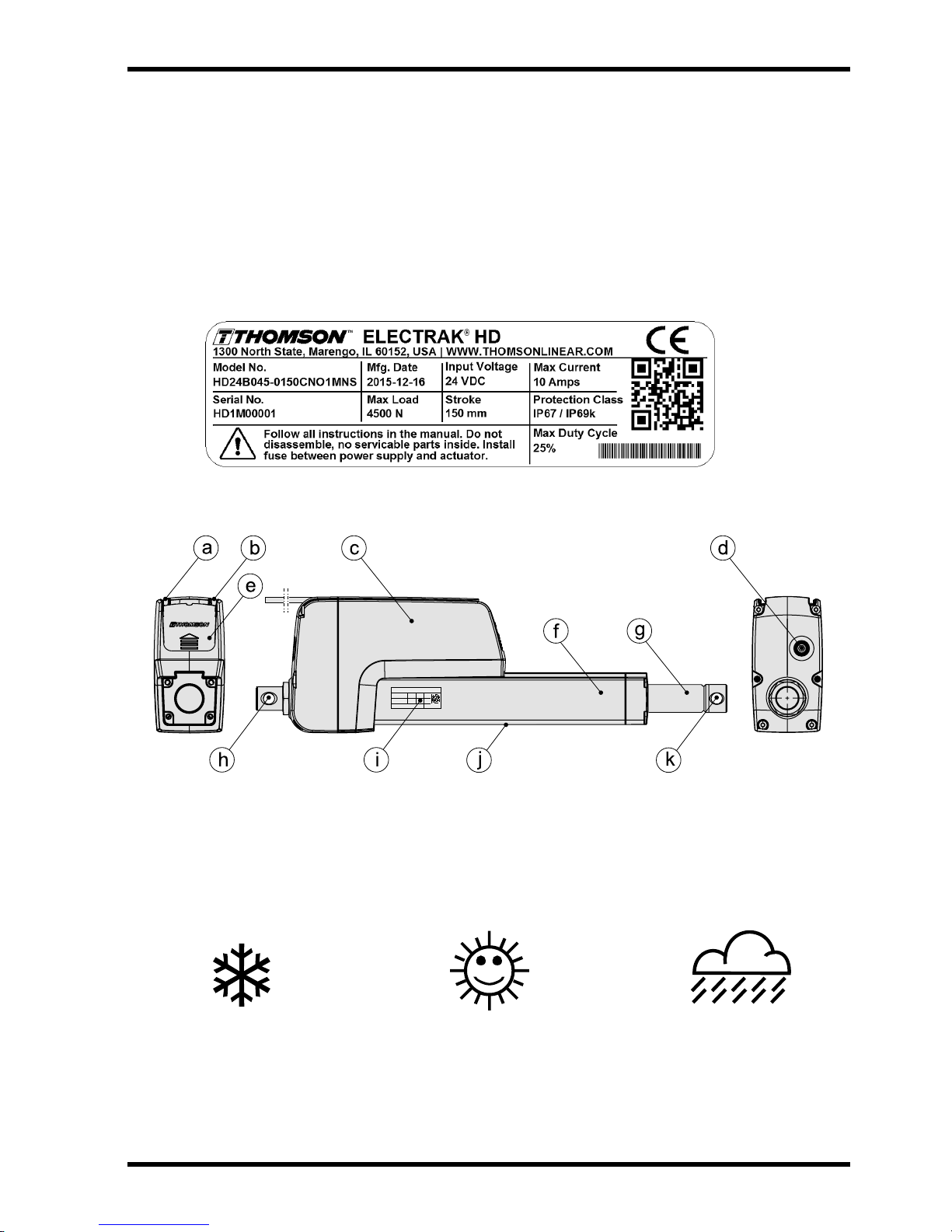
4.1 Product label
The product label can be found on the side of the cover tube. It will tell you which model of actuator
you have, its basic performance data and where it is manufactured. Please study the product label
to determine actuator type before starting any installation or service on the actuator. If you need any
assistance from Thomson, please provide the serial number, manufacturing date and the designation of
the actuator(s) in question. You can also use the QR code on the label to directly access Electrak HD
information on www.thomsonlinear.com.
4.2 Terminology
a. power cable b. signal cable c. housing
d. manual override input e. cable connector cover plate f. cover tube
g. extension tube h. rear adapter i. product label
j. limit switch slots k. front adapter
4.3 Operation environment
Min. -40° C (-40° F) Max. +85° C (+185° F) IP67 / IP69K
1. Operation temperature range is -40 to +85° Celsius (-40 to +185° Fahrenheit).
2. Protection degree against the ingress of water and particles is IP67 / IP69K.
3. Relative humidity range is 10 - 90 % non-condensing.
Thomson Electrak® HD Actuator - Installation Manual - 2016-016
Page 7
Installation
Thomson
4.4 Mechanical installation
4.4.1 General installation safety notes
• Never work on the actuator with the power switched on!
• Do not hold the extension tube while the unit is energized.
• Failure modes of the actuator should be considered to ensure it does not create harm.
4.4.2 Basic installation considerations
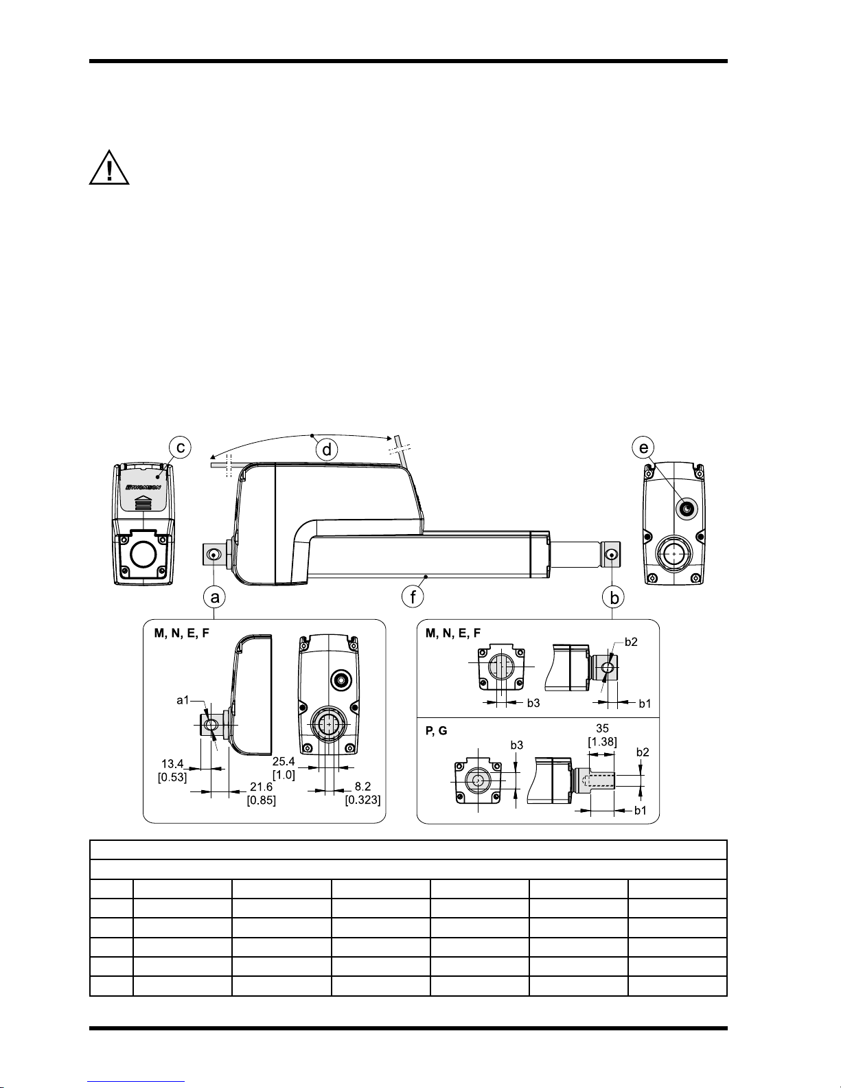
1. Only mount the actuator using the holes in the rear (a) and front (b) adapters. Check the model
number on the actuator product label (section 4.1) and then look at the ordering key (section 6.2)
to nd out your adapter type conguration. See the below drawings and table to nd out the exact
adapter dimensions.
2. Make sure that the actuator mounting position allows access to the cable connector cover plate (c), so
that it can be removed to allow access to the cable connector(s) (section 4.4.4).
3. The cable or cables (d) exit the cable slot at the rear of the actuator housing at delivery but can be
made to leave the housing at any point after the cable connector cover plate.
4. The manual override input (e) must have enough free space around it to allow it to be operated
(section 4.4.5).
5. If external limit switches will be used, the mounting of the actuator must allow access to the limit
switch slots (f) running along the underside of the cover tube (section 4.4.6).
Adapter Dimensions [mm (in)]
M E N F P G
a1 12.2 E9 (0.48) 12.8 (0.506) 12.2 E9 (0.48) 12.8 (0.506) - -
a2 - - 8.2 (0.323) 8.2 (0.323) - -
b1 10.9 (0.429) 10.9 (0.429) 12.9 (0.508) 12.9 (0.508) 30 (1.18) 30 (1.18)
b2 12.2 E9 (0.48) 12.8 (0.506) 12.2 E9 (0.48) 12.8 (0.506) M12 × 1.75 1/2-20 NF-2B
b3 - - 8.2 (0.323) 8.2 (0.323) 19 (0.748) 19 (0.748)
Thomson Electrak® HD Actuator - Installation Manual - 2016-01 7
Adapter type
Page 8
Thomson
4.4.3 Mounting orientation and forces
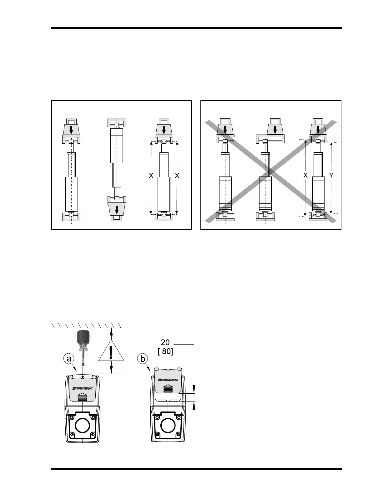
1. The actuator can be mounted in any orientation and handle both pushing and pulling loads.
2. Always install actuator so that the force of the load acts in the center of the extension tube and the
rear adapter.
3. Only mount the actuator to the rear and front adapter mounting holes.
4. Only use solid mounting pins and support them at both ends.
5. The mounting pins must be parallel to each other both radially and axially.
YES NO
4.4.4 Cable connector cover plate
1. The cover plate is held in place by a screw (M3 with Torx T10 head) that can be accessed through
the hole in the top of the cover plate (a). Keep in mind to mount the actuator so that there is enough
clearance to access the screw with a tool!
2. Once the cover plate is released it needs to be pushed about 20 mm (0.8 inch) in the direction of
the arrow symbol on the cover plate before it can be removed from the actuator (b). The connectors
are a part of the backside of the cover plate and can be accessed once the cover plate is removed.
3. Make sure to put the cover plate back correctly and torque the screw to 1.2Nm (10.6 in-lb) to ensure
that the actuator cover plate and connectors are properly sealed.
Thomson Electrak® HD Actuator - Installation Manual - 2016-018
Page 9

Thomson
4.4.5 Manual override mounting and operation
1. Make sure when mounting the actuator that there is space enough between the rear adapter and any
object behind it to allow the manual override to be operated!
2. To operate the manual override, remove the cover plug (a) using a at head screw driver. Then
turn on the manual override input hexagon key (b) using a 6 mm hexagon deepwall socket (c).
3. The maximum torque required to move the extension tube at the fully rated actuator load using the
manual override is typically 1.7 Nm (15 in-lb).
4. The distance the extension tube travels per manual override input revolution depends on the
actuator type. See the table below.
Extension Tube Movement / Manual Override Input Revolution [mm (in)]
Actuator type Movement
HDxx-B026 0.224 (0.0088)
HDxx-B045 0.134 (0.0053)
HDxx-B068 0.099 (0.0039)
HDxx-B100 0.059 (0.0023)
Always make sure to switch off the power to the actuator before using the manual override.
Do not apply higher torque than 1.7 Nm (15 in-lb) to the manual override input.
Never run the extension tube in to the end of stroke as that may damage the actuator.
Never use any type of drill or power tool to operate the manual override.
4.4.6 Mounting of optional external limit switches
1. The external limit switches are mounted in the two slots (a) at the bottom of the cover tube.
2. Put the sensor (b) into one of the slots and and lock it at the desired position by turning the clamp
screw 45 degrees (c).
If the sensor is mounted in the immediate vicinity of magnetic components, the
switching characteristics of the sensor may change.
Thomson Electrak® HD Actuator - Installation Manual - 2016-01 9
Page 10

Thomson
Installation
4.5 Electrical installation
4.5.1 General notes
• Make sure the leads/cables leading to the motor can handle the maximum motor current.
• An emergency stop is recommended to reduce the chance of a crushing hazard.
• Never work on the actuator or the wiring with the power switched on!
4.5.2 Fuse size
Protect the actuator and the wiring by using a slow blow fuse between the actuator and the power source.
Recommended Fuse Size
Actuator supply voltage Fuse size
12 VDC 40 A
24 VDC 20 A
4.5.3 Electrical connections
The actuator is always supplied with a power cable (a). Depending on which control option was selected, it
can also have a signal cable (b). The cable(s) have ying leads in one end for customer connections. In the
other end the cable(s) are integrated in to the cable connector cover plate (c) (section 4.4.4). The plug in
connector allows replacing the actuator without disconnecting the ying leads.
4.5.4 Lead cross sections
To avoid malfunction due to voltage drop the cross section of the leads between the actuator power
cable leads and the power source must be of sufcient size. For longer cables than stated in the table,
calculations based on the supply voltage, the current draw, the length of the cables and the ambient
temperature must be done.
2.5
mm2 [AWG 14]
Power cable
X
2
[AWG 20]
0.5 mm
Signal cable
Power Lead Cross Sections
Length of cable (L) Min. allowed cross section (X)
0 - 4 m
4 - 10 m 4 mm
2.5 mm2 [AWG 14]
2
[AWG 12]
Thomson Electrak® HD Actuator - Installation Manual - 2016-0110
Page 11

Installation
Thomson
4.5.5 Inrush current
At the start of the actuator there is an inrush current to the motor that will last between 75 to 150
milliseconds. See below table to determine the inrush current for the control option being used.
Control Option Inrush Current Level
Option Inrush current
EXX, ELX, EXP, EXD, ELP, ELD up to 4 × rated current for the actuator model and load in question
LXX, LLX, LXP, CNO up to 2 × rated current for the actuator model and load in question
If using an AC powered power supply it must be sized to handle the inrush current (batteries
typically have no problem delivering the inrush current). Also contacts, switches and relays must
be sized appropriately to be able to handle the inrush current.
Thomson Electrak® HD Actuator - Installation Manual - 2016-01 11
Page 12

Thomson
4.6 Control options installation and operation
4.6.1 General notes
• Avoid placing signal cables along power cables to reduce the risk of interference.
• Avoid using a vehicle earth as the return conductor. Instead use a two wire system to reduce
the risk of interference.
• In very sensitive applications or where there is a risk of interference we recommend using
shielded signal cables.
• Keep in mind that long cables in combination with small lead cross sections and low voltages
may lead to undervoltage and malfunction due to voltage drop.
• Relays or other coil operated devices should have spark protection to avoid interference.
• Never work on the actuator or the wiring with the power switched on!
4.6.2 How to determine the control option
Electrak HD is equipped with one of the control options in the table below. To determine the option
your actuator has, check the model number on the product label on the actuator (section 4.1) and then
check the ordering key (section 6.2). Use the table below and go to the corresponding section for further
information.
Control Options
Option Functions Section
EXX Electrak Monitoring Package only 4.6.3
ELX Electrak Monitoring Package + End of Stroke Indication Output 4.6.4
EXP Electrak Monitoring Package + Analog Position Output 4.6.5
EXD Electrak Monitoring Package + Digital Position Output 4.6.6
ELP Electrak Monitoring Package + End of Stroke Indication Output + Analog Position Output 4.6.7
ELD Electrak Monitoring Package + End of Stroke Indication Output + Digital Position Output 4.6.8
LXX Electrak Monitoring Package + Low Level Signal Motor Switching 4.6.9
LLX Electrak Monitoring Package + Low Level Signal Motor Switching + End of Stroke Indication Output 4.6.10
LXP Electrak Monitoring Package + Low Level Signal Motor Switching + Analog Position Output 4.6.11
CNO CAN Bus J1939 Control + Open Loop Speed Control 4.6.12
Thomson Electrak® HD Actuator - Installation Manual - 2016-0112
Page 13

Thomson
4.6.3 Control option EXX (Electrak monitoring package only)
Utilizing the internal control system the actuator will:
• Stop the actuator immeditately at each end of mechanical travel and throughout the stroke anytime
current exceeds a factory preset value for the rated load (over load condition). This value is adjusted
during operation automatically to provide consistent force. Resetting the actuator requires motion in
opposite direction to continue normal operation.
• Stop the actuator when the current move is nished in the situation where voltage or temperature
are outside their normal operating ranges. Once within the normal operating range the actuator will
automatically reset and normal operation can be continued.
Always turn power off to the actuator before working on it to eleminate the risk of the actuator
making unplanned moves after it has carried out the automatic reset.
To extend the actuator apply +Vdc to red and -Vdc to black. To retract apply -Vdc to red and +Vdc to
black.
EXX Control Option Specications
Input voltage
HD12
HD24
Max. actuator current draw [A] see product label
F Fuse
S1 Double pole double throw switch
[Vdc]
9 - 16
18 - 32
red
black
4.6.4 Control option ELX
In addition to all of the features included in the EXX version (section 4.6.3), the ELX also includes the
additional feature of end of stroke indication. These normally open outputs can be used to provide
feedback that the actuator has reached it’s mechanical minimum or maximum stroke.
To extend the actuator apply +Vdc to red and -Vdc to black. To retract apply -Vdc to red and +Vdc to
black.
ELX Control Option Specications
Input voltage
HD12
HD24
Max. actuator current draw [A] see product label
Output contact type potential free
Limit switch max. voltage [Vdc] 32
Limit switch max. current [mA] 350
Limit switch max. power [W] 5
F Fuse
S1 Double pole double throw switch
[Vdc]
9 - 16
18 - 32
output fully retracted
output fully extended
common
not used
red
black
red
white
brown
blue
black
violet
orange
grey
Thomson Electrak® HD Actuator - Installation Manual - 2016-01 13
Page 14

Thomson
4.6.5 Control option EXP
In addition to all of the features included in the EXX version (section 4.6.3), the EXP adds a
potentiomenter providing a voltage signal for the customer to use to determine position, speed and
direction.
To extend the actuator apply +Vdc to red and -Vdc to black. To retract apply -Vdc to red and +Vdc to
black.
EXP Control Option Specications
Input voltage
HD12
HD24
Max. actuator current draw [A] see product label
Potentiometer type wirewound
Potentiometer max.
input voltage
Potentiometer max.
power
Potentiometer linearity [%] ± 0.25
Potentiometer output
resolution
50 - 100 mm stroke
150 - 250 mm stroke
300 - 500 mm stroke
550 - 1000 mm stroke
4.6.6 Control option EXD
In addition to all of the features included in the EXX version (section 4.6.3), the EXD also includes an
encoder providing a single pulse train signal to determine position and speed.
[Vdc]
[Vdc] 32
[W] 1
[ohm/mm]
9 - 16
18 - 32
65.62
32.81
19.69
9.84
+ 32 Vdc
potentiometer output
not used
0 Vdc
not used
F Fuse
S1 Double pole double throw switch
red
black
red
white
brown
blue
black
violet
orange
grey
To extend the actuator apply +Vdc to red and -Vdc to black. To retract apply -Vdc to red and +Vdc to
black.
EXD Control Option Specications
Input voltage
HD12
HD24
Max. actuator current draw [A] see product label
Encoder type gear tooth
Encoder input voltage [Vdc] 4 - 24
Encoder output low
voltage levels (logical
zero)
typical / max.
Encoder resolution
HDxx-B026
HDxx-B045
HDxx-B068
HDxx-B100
[Vdc]
[Vdc]
[mm/pulse]
9 - 16
18 - 32
0.1 / 0.25
0.154
0.092
0.068
0.040
red
black
+ 5 Vdc
encoder output
not used
0 Vdc
not used
red
white
brown
blue
black
violet
orange
grey
F Fuse
S1 Double pole double throw switch
Thomson Electrak® HD Actuator - Installation Manual - 2016-0114
Page 15

Thomson
4.6.7 Control option ELP
In addition to all of the features included in the EXX version (section 4.6.3), the ELP has both end
of stroke indication and a potentiometer providing a voltage signal to determine position, speed and
direction.
To extend the actuator apply +Vdc to red and -Vdc to black. To retract apply -Vdc to red and +Vdc to
black.
ELP Control Option Specications
Input voltage
HD12
HD24
Max. actuator current draw [A] see product label
Output contact type potential free
Limit switch max. voltage [Vdc] 32
Limit switch max. current [mA] 350
Limit switch max. power [W] 5
Potentiometer type wirewound
Potentiometer max.
input voltage
Potentiometer max.
power
Potentiometer linearity [%] ± 0.25
Potentiometer output
resolution
50 - 100 mm stroke
150 - 250 mm stroke
300 - 500 mm stroke
550 - 1000 mm stroke
[Vdc]
[Vdc] 32
[W] 1
[ohm/mm]
9 - 16
18 - 32
65.62
32.81
19.69
9.84
+ 32 Vdc
potentiometer output
not used
0 Vdc
output fully retracted
output fully extended
common
F Fuse
S1 Double pole double throw switch
red
black
red
white
brown
blue
black
violet
orange
grey
Thomson Electrak® HD Actuator - Installation Manual - 2016-01 15
Page 16

Thomson
4.6.8 Control option ELD
In addition to all of the features included in the EXX version (section 4.6.3), the ELD has both end of
stroke indication and an encoder providing a single pulse train signal to determine position and speed.
To extend the actuator apply +Vdc to red and -Vdc to black. To retract apply -Vdc to red and +Vdc to
black.
ELD Control Option Specications
Input voltage
HD12
HD24
Max. actuator current draw [A] see product label
Output contact type potential free
Limit switch max. voltage [Vdc] 32
Limit switch max. current [mA] 350
Limit switch max. power [W] 5
Encoder type gear tooth
Encoder input voltage [Vdc] 4 - 24
Encoder output low
voltage levels (logical
zero)
typical / max.
Encoder resolution
HDxx-B026
HDxx-B045
HDxx-B068
HDxx-B100
[Vdc]
[Vdc]
[mm/pulse]
9 - 16
18 - 32
0.1 / 0.25
0.154
0.092
0.068
0.040
+ 5 Vdc
encoder output
not used
0 Vdc
output fully retracted
output fully extended
common
F Fuse
S1 Double pole double throw switch
red
black
red
white
brown
blue
black
violet
orange
grey
Thomson Electrak® HD Actuator - Installation Manual - 2016-0116
Page 17

Thomson
4.6.9 Control option LXX
In addition to all of the features included in the EXX version (section 4.6.3), the LXX option allows the
end user to extend, retract or stop the actuator using low current (<22 mA) input signals instead of
switching the polarity of the input power voltage.
It also includes:
• An automatic soft start capability reducing the inrush current (section 4.5.5).
• A “sleep” mode function is activated when no motion is commanded for 15 seconds. In sleep mode
the current draw is less than 1 mA for a 12 Vdc actuator and less the 2 mA for a 24 Vdc actuator. The
sleep mode will exit and return to normal operation when the next move command is received.
• Dynamic braking throughout the entire stroke length whenever a motion command is removed.
Power the actuator by connecting red to + Vdc and black to - Vdc in the power cable. To extend the
actuator apply +Vdc to violet and to retract apply +Vdc to orange in the signal cable.
LXX Control Option Specications
Input voltage
HD12
HD24
Max. actuator current draw [A] see product label
Extend / retract input voltage [Vdc] 9 - 32
Extend / retract input current [mA] 6 - 22
[Vdc]
9 - 16
18 - 32
F Fuse
S1 Extend switch
S2 Retract switch
not used
+
–
red
black
red
white
brown
blue
black
violet
orange
grey
4.6.10 Control option LLX
In addition to all of the features included in the LXX version (section 4.6.9), LLX also includes end of
stroke indication. These normally open outputs can be used to provide feedback that the actuator has
–
reached it’s mechanical minimum or maximum stroke.
Power the actuator by connecting red to + Vdc and black to - Vdc in the power cable. To extend the
actuator apply +Vdc to violet and to retract apply +Vdc to orange in the signal cable.
LLX Control Option Specications
Input voltage
HD12
HD24
Max. actuator current draw [A] see product label
Output contact type potential free
Limit switch max. voltage [Vdc] 32
Limit switch max. current [mA] 350
Limit switch max. power [W] 5
Extend / retract input voltage [Vdc] 9 - 32
Extend / retract input current [mA] 6 - 22
[Vdc]
Thomson Electrak® HD Actuator - Installation Manual - 2016-01 17
9 - 16
18 - 32
F Fuse
S1 Extend switch
S2 Retract switch
common
output fully extended
not used
output fully retracted
+
–
red
black
red
white
brown
blue
black
violet
orange
grey
Page 18

Thomson
4.6.11 Control option LXP
In addition to all of the features included in the LXX version (section 4.6.9), LXP also includes a
potentiometer providing a voltage signal for the customer to use to determine position, speed and
direction.
Power the actuator by connecting red to + Vdc and black to - Vdc in the power cable. To extend the
actuator apply +Vdc to violet and to retract apply +Vdc to orange in the signal cable.
LXP Control Option Specications
Input voltage
HD12
HD24
Max. actuator current draw [A] see product label
Potentiometer type wirewound
Potentiometer max.
input voltage
Potentiometer max.
power
Potentiometer linearity [%] ± 0.25
Potentiometer output
resolution
50 - 100 mm stroke
150 - 250 mm stroke
300 - 500 mm stroke
550 - 1000 mm stroke
Extend / retract input voltage [Vdc] 9 - 32
Extend / retract input current [mA] 6 - 22
[Vdc]
9 - 16
18 - 32
[Vdc] 32
[W] 1
[ohm/mm]
65.62
32.81
19.69
9.84
F Fuse
S1 Extend switch
S2 Retract switch
32 Vdc
potentiometer output
not used
0 Vdc
+
–
red
black
red
white
brown
blue
black
violet
orange
grey
Thomson Electrak® HD Actuator - Installation Manual - 2016-0118
Page 19

Thomson
4.6.12 Control option CNO
This document assumes the reader is familiar with the SAE J1939 standard. Terminology
from the standard is used, but not described in detail. See section 5 for information on the
CAN Bus operation and communication protocol.
4.6.12.1 General installation data
Voltage is to be directly connected to the actuator. All motion and protection on the CAN Bus option is
handled through the CAN messages including overload protection. Please see section 5 for more details
on the messages.
CNO Control Option Specications
Input voltage
HD12
HD24
Max. actuator current draw [A] see product label
[Vdc]
9 - 16
18 - 32
F Fuse
address select 3
CAN Low
CAN High
address select 1
address select 2
address select common
not used
not used
red
black
red
white
brown
blue
black
violet
orange
grey
4.6.12.2 CAN Bus SAE J1939 installation data
Follow wiring guidelines per ISO-11898 Standard CAN 2.0B, Protocol SAE J1939. Proper termination
resistors (120 Ohm) should be placed in mating wire harness, see below. Please refer to section 5 for
more communication details.
CAN CAN Bus device in actuator or other equipment
R Resistor
Thomson Electrak® HD Actuator - Installation Manual - 2016-01 19
Page 20

Thomson
5. CAN Bus information
5.1 Introduction to CANBUS SAE J1939
This document assumes the reader is familiar with the SAE J1939 standard. Terminology from the
standard is used, but not described in detail. The Electrak® HD actuator is compliant with the standard
J1939, and supports the following PGNs (Parameter Group Number) from the standard.
J1939-21 – Data Link Layer
• Proprietary A 61184 (0x00EF00)
• Proprietary A2 126720 (0x01EF00)
J1939-81 – Network Management
• Address Claimed/Cannot Claim 60928 (0x00EE00)
• Commanded Address 65240 (0x00FED8)
5.2 CANBUS SAE J1939 communications protocol
5.2.1 J1939 NAME
The Electrak HD has the following defaults for the J1939 NAME. Please refer to the SAE J1939/81
standard for more information on these parameters.
J1939 NAME Defaults
Arbitrary Address Capable Yes
Industry Group 0, Global
Vehicle System Instance 0
Vehicle System 0, Non-specic system
Function 255, Not available
ECU Instance 0, First instance
Manufacture Code 547, Thomson Linear LLC
Identity Number 0
5.2.2 Address
The Electrak HD uses a default address value of 19 (0x13). In applications where the default address is
not available, there are three additional methods in choosing a new address.
1. The Electrak HD device is arbitrary address capable, if another device with a higher priority NAME
contends for the selected address, the actuator will continue to request other addresses until it nds
one that it can claim.
2. The Electrak HD device can also use the commanded address PGN to select a specied address.
See J1939/81 for more details about address claiming.
3. In some applications it may be more convenient to select an address through hardware means. In
this case the user can change the default address using the address select wires as dened in
section 4.6.12. Activating individual select pins will create a binary adder to the default address. This
method can allow up to 8 individual actuator addresses on a single bus. The below chart shows some
examples on how this can be implemented.
Address Select
Address select common Address select 3 Address select 2 Address select 1 Binary adder Default address
Gnd 0 0 0 0 19 (0x13)
Gnd 0 0 1 1 20 (0x14)
Gnd 0 1 0 2 21 (0x15)
Gnd 1 1 1 7 26 (0x20)
...
Thomson Electrak® HD Actuator - Installation Manual - 2016-0120
Page 21

Thomson
5.2.3 Sleep operation
The Electrak HD utilizes a sleep mode operation when positioning is no longer required. This feature
allows for a constant battery connection with minimal drain while the engine or vehicle is not running.
After 5 seconds of bus inactivity, the actuator will put itself in a state of sleep. During this state the
quiescent current is <1 mA for 12 Vdc models and <2 mA for 24 Vdc models. When bus activity is
restored the actuator will begin a wake up phase, followed by an address claim request.
5.2.4 J1939 actuator control message (ACM)
All actuator control parameters are adjustable through the proprietary A message (PGN 61184). The
preferred transmission repetition rate is 100ms (can also be sent as required by the application.)
Additional message specic information can be found in the table below, all other Proprietary A
information can be found in the SAE J1939/21 specication.
Actuator Control Message Signal Information
Start position Length Parameter name
1.1 14 bits Position command
2.7 9 bits Current limit
3.8 5 bits Speed command
4.5 1 bit Motion enable
4.6 35 bits Factory use
The least signicant bit of each message is indicated by the start position column
5.2.4.1 Position command
This 14-bit signal is used to set the target position for the next actuator motion. Although resolution
of the signal is represented as 0.1 mm/bit, true positional accuracy will be dependent on the stroke
length of the given model. The actuator uses an internally calculated deadband value to determine
when within a target position range. The 0.0 mm and full extend stroke values represent 0 to 100%
stroke and are only relative to the actual available stroke of the individual unit.
Range: 0.0 mm to 1000.0 mm
Resolution: 0.1 mm/bit, 0 offset
5.2.4.2 Current limit
This 9-bit signal is used to set a current at which the actuator will cease motion. In the event a
force is applied to the actuator that causes the motor current to exceed this settable value for more
than 50 ms, the actuator will stop any current motion and activate a dynamic breaking effect on the
motor. This current limit does not apply during the motor starting phase where in rush current can be
signicantly higher than normal running.
Range: 0.0 A to 25.0 A (12Vdc actuator), 0.0A to 12.5 A (24Vdc actuator)
Resolution: 0.1 A/bit, 0 offset
5.2.4.3 Speed command
This 5-bit signal is used to set the speed of the actuator. The signal adjusts the PWM driver within
the actuator and the voltage applied to the motor. The resultant actuator speed will be a ratio of the
actuators max speed and also dependent on the load applied to the actuator.
Range: 0% to 100% motor duty cycle
Resolution: 5%/bit, 0 offset
5.2.4.4 Motion enable
This 1-bit signal is used to enable motion from the actuator. If this bit is low (0), no motion will be
allowed. This signal can be used to dene the next actuator movement message without starting the
motor. When movement is required this bit can be changed to high (1) and motion will begin using
the other parameter signals encoded in the ACM.
Thomson Electrak® HD Actuator - Installation Manual - 2016-01 21
Page 22

Thomson
5.2.4.5 Factory use
The remaining 35 bits of the ACM are used for factory calibration use only and should be lled with
0x00 or 0xFF when sending this message.
5.2.5 J1939 actuator feedback message (AFM)
All actuator feedback data can be retrieved through the proprietary A2 message (PGN 126720). This
message is transmitted every 100ms. Additional message specic information can be found in Table
2, all other Proprietary A2 information can be found in the SAE J1939/21 specication.
Actuator Feedback Message Signal Information
Start position Length Parameter name
1.1 14 bits Measured position
2.7 9 bits Measured current
3.8 5 bits Running speed
4.5 2 bits Voltage error
4.7 2 bits Temperature error
5.1 1 bit Motion ag
5.2 1 bit Overload ag
5.3 1 bit Backdrive ag
5.4 1 bit Parameter ag
5.5 1 bit Saturation ag
5.6 1 bit Fatal error ag
5.7 18 bits Factory use
The least signicant bit of each message is indicated by the start position column
5.2.5.1 Measured position
This 14-bit signal is used to inform the user of the actual actuator stroke position. Although
resolution of the signal is represented as 0.1 mm/bit, true positional accuracy will be dependent on
the stroke length of the given model. The actuator uses an internally calculated deadband value to
determine when it is within a target position range. The 0.0 mm and ordered full extend stroke values
represent 0 to 100% stroke but the signaled value does not take in to account any mechanical
tolerances or play in the actuator.
Range: 0.0 mm to 1000.0 mm
Resolution: 0.1 mm/bit, 0 offset
5.2.5.2 Measured current
This 9-bit signal is used to inform the user of the actual current being drawn used by the actuator.
Range: 0.0 A to 51.1 A
Resolution: 0.1 A/bit, 0 offset
5.2.5.3 Running speed
This 5-bit signal is used to inform the user of the actual duty cycle being applied to the motor
through the internal actuator controller.
Range: 0% to 100% motor duty cycle
Resolution: 5%/bit, 0 offset
5.2.5.4 Voltage error
This 2-bit signal is used to inform the user that the operational voltage is outside of allowable
running parameters. Any motion already in progress will continue until completed, but additional
movement request will not be allowed until the operational voltage returns within the normal
operating range.
Thomson Electrak® HD Actuator - Installation Manual - 2016-0122
Page 23

Thomson
Voltage Error Message
00 Input voltage within operational range
01 Input voltage below operational range
10 Input voltage above operational range
11 Not used
5.2.5.5 Temperature error
This 2-bit signal is used to inform the user that the operational temperature is outside of allowable
running parameters. Any motion already in progress will continue until completed, but additional
movement request will not be allowed until the operational temperature returns within the normal
operating range.
Temperature Error Message
00 Temperature within operational range
01 Temperature below operational range
10 Temperature above operational range
11 Not used
5.2.5.6 Motion ag
This 1-bit signal is used to inform the user that the actuator is currently in motion.
5.2.5.7 Overload ag
This 1-bit signal is used to inform the user that the last motion the actuator completed caused a
current over load condition. This occurs when the actuator determines the current set in the Current
Limit signal from the ACM is exceeded for a consecutive 50ms. When this ag is set by the actuator
the user must reset the Motion Enable ag in the ACM before attempting additional motion from the
actuator.
5.2.5.8 Backdrive ag
This 1-bit signal is used to inform the user that the actuator has determined positional movement in
the extension tube that was not commanded from the user. This can be caused from excessive static
load or vibration being applied to the actuator.
5.2.5.9 Parameter ag
This 1-bit signal is used to inform the user that one of the parameter signals in the ACM is outside
the allowed parameters the specic model will allow. To prevent damage to the actuator motion is
not allowed while this ag is set.
5.2.5.10 Saturation ag
This 1-bit signal is used to inform the user that the actuator is currently running within 10% of its
maximum capability. Additional speed or current needed from the application may not be able to be
obtained with the chosen actuator model.
5.2.5.11 Fatal error ag
This 1-bit signal is used to inform the user that the actuator needs service. If this ag is set power
can be reset to determine if the ag is resettable, but it is suggested to contact the factory for
additional support. To prevent possible additional damage motion is prohibited while this ag is set.
5.2.5.12 Factory use
The remaining 18 bits of the Actuator Feedback Message are used for factory calibration use only
and under normal operation will be returned with 0x00.
Thomson Electrak® HD Actuator - Installation Manual - 2016-01 23
Page 24

Thomson
6. Technical specications
6.1 Technical data
Technical Specication HD • •
Input voltage [VDC] 12 24
Input voltage tolerance [VDC] 9 - 16 18 - 32
Stroke length [mm] see product label
Static load at fully retracted (Fx), maximum [kN (lbs)] 18 (4050)
Dynamic load (Fx), maximum [N] see product label
Speed, no load / max. rated load
HDxx-B026
HDxx-B045
HDxx-B068
HDxx-B100
Current draw @ rated max. load [A] see product label
[mm/s (inch/s)]
40 / 32 (1.6 / 1.3)
24 / 19 (0.94 / 0.75)
18 / 14 (0.71 / 0.55)
11 / 9 (0.43 / 0.35)
Weight [kg (lbs)]
End play, maximum [mm (in)]
Operating temperature limits, standard units [°C (°F)]
Full load duty cycle @ 25 °C [%] see product label
Restraining torque [Nm (lbf-in)] 0 (internally restrained)
2
Motor cable lead cross section [mm
Signal cable lead cross section [mm
Cable length (depending on option) [mm (in)] 0.3 (11.8), 1.5 (59) or 5 (197)
Protection class - static IP67 / IP69K
Protection class - dynamic IP66
Safety features
static load holding brake
internal end-of-stroke limit switches
overload protection
temperature monitoring
temperature compensation
voltage monitoring
Certications CE, RoHS
Actuator Weight [kg]*
Actuator
model
100 150 200 250 300 350 400 450 500 550 600 650 700 750 800 850 900 950 1000
(AWG)] 2 (14)
2
(AWG)] 0.5 (20)
Stroke (see product label) [mm]
see table below
1.2 (0.047)
- 40 to + 85 (- 40 to + 185)
yes
yes
yes
yes
yes
yes
HDxx-B026 6.5 6.7 7.0 7.2 7.5 7.7 8.0 8.2 8.5 8.7 9.0 9.2 9.5 9.7 10.0 10.2 11.6 11.9 12.2
HDxx-B045 6.5 6.7 7.0 7.2 7.5 7.7 8.0 8.2 8.5 8.7 9.0 9.2 10.4 10.7 11.0 11.3 11.6 11.9 12.2
HDxx-B068 6.5 6.7 7.0 7.2 7.5 7.7 8.0 8.2 8.5 9.5 9.8 10.1 10.4 10.7 11.0 11.3 11.6 11.9 12.2
HDxx-B100 6.7 7.0 7.2 7.5 7.7 8.0 8.2 9.1 9.4 9.7 10.0 10.3 10.6 10.9 11.2 11.5 11.8 12.1 12.4
* Conversion factor for kilogram to pound: 1 kg = 2.204623 lbs
Thomson Electrak® HD Actuator - Installation Manual - 2016-0124
Page 25

Thomson
6.2 Ordering key
Ordering Key
Position 1 2 3 4 5 6 7 8
Example
1. Actuator type and supply voltage
HD12 = Electrak HD, 12 Vdc
HD24 = Electrak HD, 24 Vdc
2. Screw type, dynamic load capacity
B026- = ball screw, 2.6 kN (585 lbs)
B045- = ball screw, 4.5 kN (1012 lbs)
B068- = ball screw, 6.8 kN (1529 lbs)
B100- = ball screw, 10 kN (2248 lbs)
3. Ordering stroke length
0100 = 100 mm
0150 = 150 mm
0200 = 200 mm
0250 = 250 mm
0300 = 300 mm
0350 = 350 mm
0400 = 400 mm
0450 = 450 mm
0500 = 500 mm
0550 = 550 mm
0600 = 600 mm
0650 = 650 mm
0700 = 700 mm
0750 = 750 mm
0800 = 800 mm
0850 = 850 mm
0900 = 900 mm
0950 = 950 mm
1000 = 1000 mm
HD12 B026- 0300 LXX 2 M M
S
4. Electrak® Modular Control System options
EXX = Electronic Monitoring Package only
ELX = EXX + end-of-stroke indication output
EXP = EXX + analog (potentiometer) position output
EXD = EXX + digital position output
ELP = ELX + analog (potentiometer) position output
ELD = ELX + digital position output
LXX = EXX + low-level signal motor switching
LLX = EXX + LXX + end-of-stroke indication output
LXP = EXX + LXX +analog (potentiometer) position output
CNO = Can bus J1939 + open loop speed control
5. Harness option
1 = 0.3 m long cables with ying leads
2 = 1.5 m long cables with ying leads
3 = 5.0 m long cables with ying leads
6. Rear adapter option
M = cross hole for 12 mm pin
E = cross hole for ½ inch pin
N = forked cross hole for 12 mm pin
F = forked cross hole for ½ inch pin
7. Front adapter option
M = cross hole for 12 mm pin
E = cross hole for ½ inch pin
N = forked cross hole for 12 mm pin
F = forked cross hole for ½ inch pin
P = metric female thread
G = inch female thread
Thomson Electrak® HD Actuator - Installation Manual - 2016-01 25
8. Adapter orientation
S = standard
M = 90 ° turned
Page 26

USA, CANADA and MEXICO
Thomson
203A West Rock Road
Radford, VA 24141, USA
Phone: 1-540-633-3549
Fax: 1-540-633-0294
E-mail: thomson@thomsonlinear.com
Literature: literature.thomsonlinear.com
EUROPE
United Kingdom
Thomson
Office 9, The Barns
Caddsdown Business Park
Bideford, Devon, EX39 3BT
Phone: +44 (0) 1271 334 500
E-mail: sales.uk@thomsonlinear.com
Germany
Thomson
Nürtinger Straße 70
72649 Wolfschlugen
Phone: +49 (0) 7022 504 403
Fax: +49 (0) 7022 504 405
E-mail: sales.germany@thomsonlinear.com
France
Thomson
Phone: +33 (0) 243 50 03 30
Fax: +33 (0) 243 50 03 39
E-mail: sales.france@thomsonlinear.com
Italy
Thomson
Largo Brughetti
20030 Bovisio Masciago
Phone: +39 0362 594260
Fax: +39 0362 594263
E-mail: info@thomsonlinear.it
Spain
Thomson
E-mail: sales.esm@thomsonlinear.com
Sweden
Thomson
Estridsväg 10
29109 Kristianstad
Phone: +46 (0) 44 24 67 00
Fax: +46 (0) 44 24 40 85
E-mail: sales.scandinavia@thomsonlinear.com
ASIA
Asia Paci ic
E-mail: sales.apac@thomsonlinear.com
China
Thomson
Rm 2205, Scitech Tower
22 Jianguomen Wai Street
Beijing 100004
Phone: +86 400 6661 802
Fax: +86 10 6515 0263
E-mail: sales.china@thomsonlinear.com
India
Thomson
c/o CNRG Energy India Pvt., Ltd.
Unit No. FF A 07
Art Guild House, A Wing, 1st Floor, L.B.S. Marg
Kurla - West, Mumbai - 400070 India
Phone. +0091 22 6249 5043
E-mail: sales.india@thomsonlinear.com
Japan
Thomson
Minami-Kaneden 2-12-23, Suita
Osaka 564-0044 Japan
Phone: +81-6-6386-8001
Fax: +81-6-6386-5022
E-mail: csjapan@
South Korea
Thomson
F12 Ilsong Bldg,
507, Teheran-ro, Gangnam-gu,
Seoul, Korea, Zip Code: 06168
Phone: +82 2 6917 5048 & 5049
Fax: +82 2 528 1456 & 1457
E-mail: sales.korea@thomsonlinear.com
SOUTH AMERICA
Brazil
Thomson
Av. Tambore, 1077
Barueri, SP - 06460-000
Phone: +55 11 3616-0191
Fax: +55 11 3611 1982
Email: sales.brasil@thomsonlinear.com
scgap.com
www.thomsonlinear.com
Electrak_HD_Installation_Operation_MNEN-0003-02 | 20170726KB
Specifications are subject to change without notice. It is the responsibility of the product user to determine the suitability of
this product for a specific application. All trademarks property of their respective owners. ©2017 Thomson Industries, Inc.
 Loading...