

Page 1

RP C21
First issue 09 / 01
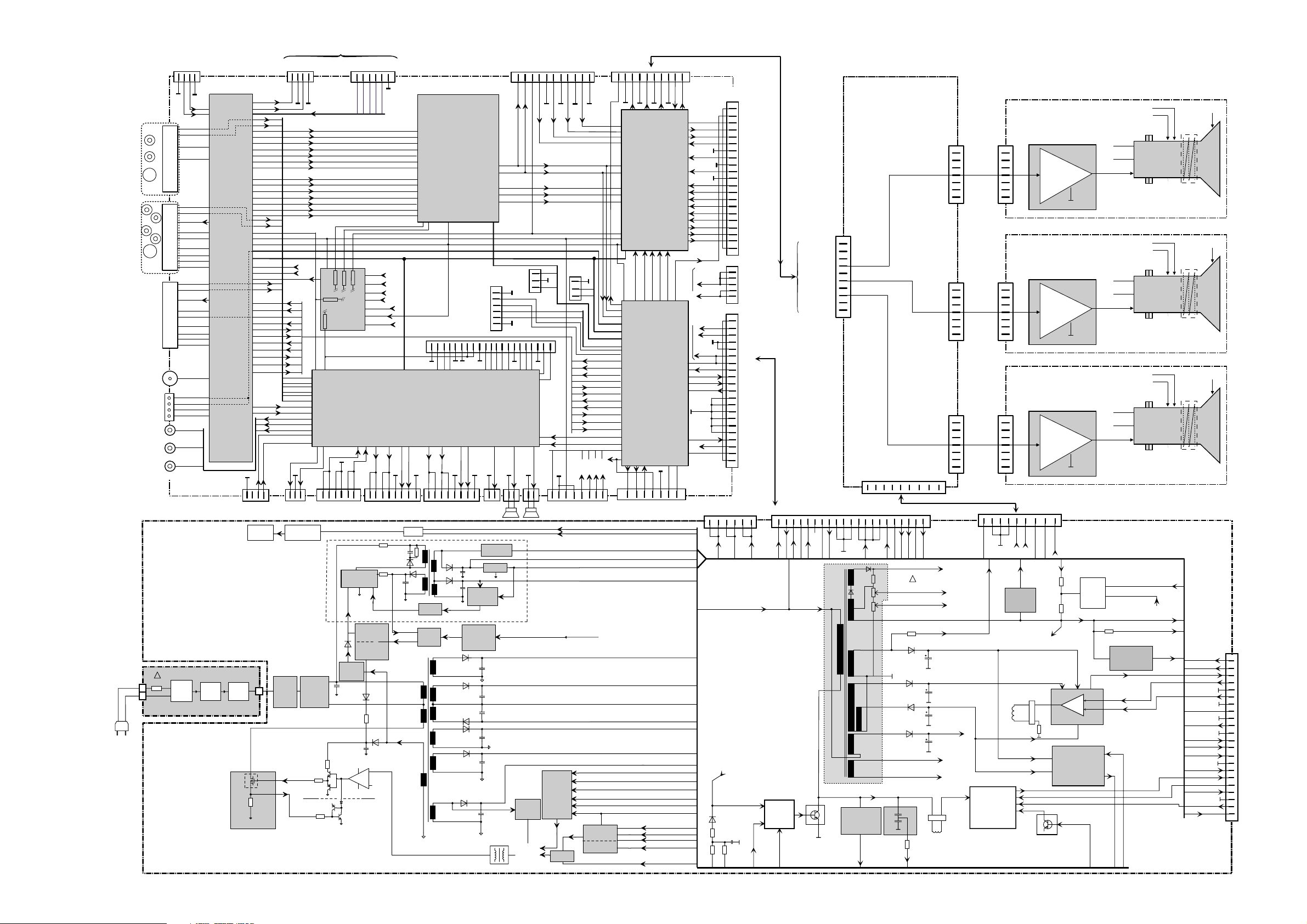
WIRING DIAGRAM - SCHEMA D’INTERCONNEXIONS - VERDRAHTUNGSPLAN - DIAGRAMMA DELLE INTERCONNESSIONI - ESQUEMA DE INTERCONEXIONES
200
2
1
1
10
11
6
4
7
3
28
395
7
2
5
5
21
21
focus
EHT
LL008
BP150
RP only
RP Convergern
(Gemstar Mod.VGA)
SSB 21000 00
BV010
BR002
BV300
BR001
BP500
IR001
IR110
IR130
BX004
BV001
BP501
IU002
IU003
IU030
IC700
BA005
NH500
BA010
BA019
BA017
BA018
IA001
IA180
BA012
1
1
1
1
1
1
1
1
1
1
1
1
1
1
1
1
1
1
BA009
BA007
BP010
BP130
BP120
BX100
BX200
1
1
1
1
1
1
1
1
1
1
1
1
1
BP001
LP050
BL035
BP005
BL111
BF001
BL200
BL500
NH001
BX300
BX001
IA002
2
BR01
BB01
CONVERGENCE SIGNAL
BOARD
CSB
POWER SUPPLY
PS
CAB
CONVERGENCE AMPLIFIER BOARD
11
12
7
9
220
8
2
2
9
2
2
2
3
SWITCH
MAINS
BK10
BK16
BK04
BK02
BK11
BS01
BK01
STV2050
BW05
BW16
BG01
ADAPTER SECTION
BP201
BP210
BP202
BP203
BP260
BW04
1
ADAPTER BOARD
ADB
RED
GREEN
BV23
1
1
111
1
Carrier
Carrier
Carrier
GND
GND
GND
99
1
4
4
4
4
44
1
1
4
7
7
9
1
9
9
2
2
2
111
1
1
1
1
1
1
1
4
1
BV01 BV03 BV04
BV02
BV05
BV96
BV07BV08
BV12
BV11
BV13
BV15
BV16
BV17
BV14
BV18
BV10
BV09
BV20
BV19
EHT
SPLITTER
B
G
R
EHT
Power Supply section
FOCUS
GRID2
FOC INP
FOC.
DYN.
GND
R
G
B
FOCUS BLOCK
BG103
BB151
BB170
BB158
BB103
BB101
CRTR
BG303
BB351
BB370
BB358
BB303
BB301
CRTG
CRT
B
BG203
BB251
BB270
BB258
BB203
BB201
FOC
FOC
FOC
CRT
CRT
CRT
CRT BOARD
CRT BOARD
CRT BOARD
BLUE
BSVM
BSVM
BSVM
Conv.
Conv.
Conv.
Vert.
Vert.
Vert.
Horiz.
Horiz.
Horiz.
TUBE
TUBE
TUBE
PICTURE
PICTURE
PICTURE
OF
:
KDB21XXX
7
7
PA/SW 20000 00
KEYBOARD
2
8 Sensor Autoconvergence*
*
* No Inserted in
some models
.......8x......
335
IR2100
GK01
BA09
BA10
BK02
BK01
BS01
BA06
BA03
BA01
BS02BA07BA04BA02
BA08
SK004
SK003
SK002
SK001
BA05
2
2
2
2
2
2
22
bass boomer
bass
boomer
2
2
RIGHT
LEFT
BA400
BA401
BQ012
BJ011
BQ009
BJ004
BJ010
FCB MODULE
1
1
GE001
BK001
A1
BP401
BP402
MIS 21000
27
7
7
1
9
8
4
4
4
PSB 21000 00
Page 2
RP C21
First issue 09 / 01
BP005
BL200
BV11
5/BL200
9/BL200
6/BL200
BP130
1
21
1
+8V
Defl. saf.
+40V
+8V
+20V
+5V
Beam Info
Dynamic phase compens.
Peak white
limiter circuit
Beam info
to tube
Focus
Pwm_pulse
G2
EHT
+UVERT
(D,~16V)
U Video
(D,~195V)
+UVFB
(D,~40..50V)
+UVFB (D,~40..50V)
+UVERT (D,~16V)
+UVERT
SSC_V_GUARD
V drive +
V drive +
V drive -
V drive -
-UVERT
-UVERT
(~-16V)
-UVERT
Correction
Earth Field
EFC
Phi2 ref
Phi2 ref
Breathing
EW prot
EW prot
EW drive
EW drive
Transistor
TL029
TL104
EW-
Modulator
Diode
Driver
Line
H drive
+20V
+20V
Beam info
V-Yoke
USYS
USYS
+
-
GNDL
DL251
RL252
10
12
7
5
1
11
9
6
3
4
DL221
DL231
GNDL
GNDL
DL201
TL010
ON4977
TL003
TL004 / TL005
TL003/4/5
Hor.Yoke
BL035
Heater high
Heater high
Heater low
Heater low
FW adj
FW adj
DPC
PKS
U_VERT
DPC
PKS
TL311
TL312
DL301/302/303
RL301
Driver
Line
LL008
!
Degauss
Aqr on
Pan Switch
Inf pow fail
+8VSTBY
+UA
GNDS
-UA
IF001
TDA8177F
PO
CNT2_20V
CNT1_20V
+5V_UP
Reset
H drive
H drive
Pan Switch
Rotation
EFC
Pan Switch
BL111
21
1
+20V
CNT1_20V
EFC
GNDL
GNDL
SSC 2H
Defl. saf.
H defl prot
DL043 / RL043
CL043
EHT circuit
safety
H defl prot
H- Flyback
Beam-info
Phi2 ref
CL030
Phi2
loop
circuit
Breathing
circuit
DL305
RL302
Breathing
1
9
9
1
Rotation
USYS
Pwm_pulse
USYS
U Video
to BV001 SIGNAL BOARD
BP130=>BA010
(SIGNAL BOARD)
SCAN PART
ADAPTER BOARD
CRT R
CRT G
CRT B
POWER / SCAN BOARD
PSB
SCART1
SCART2
SCART3
FCB
Antenne
I2C/Video
Audio out
FRONT
END
PART
IC700
TDA9321H
High Lvl Input
Processor
NH503
CTT 5010
Tuner pan euro
AUDIO PART
IA001 MSP3411G
Digital Sound Processing
IA003 MC4558 OP Ampl
IA002 TDA7269
Stereo Power Amplifier
IA180 TEA6422
Audio Switch
REMOTE PART
IR001 Gencam
µP RISC
IR004 MC34164
IC Reset
IR005 MC24C64
NVM
IR006 TCE2ACU
Bus expand
IR110 MT48LC4M
DRAM
IR130 MX29L3211
Flash mem.
UP CONVERTER
IV304 LM358
OP Amplifier
IU001 LM358
OP Amplifier
IU002 SDA9206
AD Convert
IU003 SDA9206
AD Convert
IU004 TL431
géné Vref.
IV030 SDA9410
Up Conv.
VIDEO PART
IV100 TDA9178
Picture Signal Improv
IV200 TDA9330
High Level Output
Processor
IV520 LM358
OPAmplifier
IV521 LM358
OPAmplifier
1
BV300
21
1
1
1
1
1
BW004 <=BR004
( Dolby Digital)
NH501
CTT5010
Tuner pan euro
NH500
Power-splitter
IC500
TDA9321H
High Lvl Input
Processor
IC900
TDA9181
comb filter
IX600
TEA6415
video switch
IX900
TDA8601
RGB switch
BX300 - SCART3
BX004
BX200 - SCART2
BX100 - SCART1
BX001
BA005
1
1
Front out L
Front out R
BA022
=>BA400
SOUND MODULE
CENTER CHANNEL
BA007
=>BA400
SOUND MODULE
SUBWOOFER
BA010
=>BP130
POWER BOARD
BA009
=>
BQ009 FCB
BA001
=>
BS001 TAK
1
Center Mute
Center
Center
- Us
+ Us
1
I2C
BA019
BA018
R
L
BA017
SW
1
1
10
1
BR011
BX006
BX 802
=> BV002
BX 801
=> BV001
1
SPP PART
FP501
FP510
FP521
FP530
FP520
Audio3 L/R
Chroma in
Video/Y in
Audio1 L/R
Chroma in
Video/Y in
RGB+FB in
Video out
RF in
AV1 pin8
AV link
Audio2 L/R
Chroma in
Video/Y in
RGB+FB in
Video out
AV2 pin8
AV link
I2Cdata
I2Cclock
Masse
Video in
Audio out
Head out L/R
Mute Subw
Subwoofer
EW Drive
Breathing
Phi2 ref
EW prot
PKS
Beam info
DPC
H defl prot
FW adj
EFC
Defl safe
V drive -
V drive +
SSC 2H
Eco stby
40V
PO
GND
Inf pow fail
Aqr on
Degauss
Bsvm blk
R out
G out
Blk curr
B out
G2 adj
Y M in
U M in
V M in
VDFL
HDFL
SIF
AM AF
Audio1 L/R
Audio2 L/R
Audio3 L/R
"Digit" AF in
1
I2CBus2
I2C
Bus2
Hsync M
Vsync M
FB osd
G osd
B osd
Master mute
AVlink
Audio Reset
FB2force
I2Cbus1
Trap info
Cvbs txt
B Txt
G Txt
R Txt
FB Txt
Safety Enable
D
D
C
C
LedR
Keyb
IR
LedG
8V_1H
5V_V
- Us
+ Us
+ Us
- Us
G2 adj
FB1force
8V_2H
FP det
EFC
FB1det
R osd
H Drive
Tub detec
Y 2H out
U 2H out
V 2H out
1
BV010* (* RP only)
11
R© in
8V_2H
HDFL
VDFL
V© in
B© in
Blk© in
D
C
FB2clear
FB1clear
I2Cbus2
I2Cbus4
AV1pin8
AV2pin8
FB2det
I2Cbus3
1
BR002*
D
C
1
Reset
On
3V3up
5Vup
5Vup
5V stby
3V3 stby
20V
Safety
1
10V
6V
To SP PART
I2Cbus3
I2Cbus2
I2Cbus1
5V_V
AVlink
FB2force
Trap info
Cvbs txt
FB1force
FB1det
FB2clear
FB1clear
AV1pin8
AV2pin8
FB2det
5Vstby
5Vstby
Clk M
Y S in
U S in
V S in
Hsync S
Vsync S
Clk S
5Vup
5Vup
I2Cbus1
I2Cbus2
L
R
SW
CVBS
CHR
40V
BX 810 (Not used)
1
CHR
CVBS
Digit in
Tak
5Vstby
I2Cbus3
3V3
40V
40V
3V3 stby
5V stby
20V
20V
Safety
10V
10V
6V
6V
1V8 stby
5V_A
8V_1H
20V
20V
5V stby
5V_V
Cvbs M in
Cvbs S in
RGB Tak
Sync
FB
B
G
R
BA020
BA020 => BS301
DOLBY MODULE
Module TAK
BV001=>BL111
POWER
BOARD
BP501 =>BP150
POWER
BOARD
BP500 =>BP005
POWER
BOARD
BR001
=> BK001 KEYBOARD
BA012
BA021
TAK MOD.
DP021
DP220
LP020
DP240
DRAIN
CO
M
P
O
SC
DP023
CP
023
DP061
CP030
RP030
TP051
TP081
TP050
IP030
IP070
3
2
IP050
A
TP080
TP020
IN
1
OUT
2
3
IP250
IP240
DP080
PG
ND
G
ND
GND
GND
PGND
PG
ND
PG
ND
PG
ND
PG
ND
PGND
+UA
-UA
USYS
7V_STBY
+6V
6V
+6V are heatsinks foreseen
For the diodes of Usys and
Degaussing
Picture
Tube
Relay
Power-Fail
Info
Opto
Coupler
Reg.
3V3_STBY
7V_STBY(P)
VIPER20
VDD
Opto
Coupler
On/Off
TP150
Standby
Low Power
Frequency
Shift
Prim
ary
Control
Supply
Heatsink
Power-Stage
Driver Circuit
Current
Lim
itation
3V3_STBY(RP)
5V_STBY(RP)
DEG
AUSS(RP)
10V(P)
+UA
GND_UA
-UA
20V(P)
10V(P)
USYS(P)
SM
PS
O
N/OFF
Circuit
Protection
Overvoltage
Safety
-UA(P)
+UA(P)
PW
M
Conver
sion
Control
Dem
agn.
PO
(RP)
PW
M
Secondary
Regula
tion
O
scillator
20V(P)
20V(P)
6V(P)
SAFETY
SAFETY
Stand-By Power-Supply
ECO
_TIM
ER(RP)
5V_STBY(P)
7V_STBY(P)
USYS(P)
+6V (P)
AQ
R_ON(RP)
Bridge
(O
ptional)
PFC
Rectifier
M
IS - board
Synchro
6V(P)
7V_STBY
INF_PO
W
_FAIL(RP)
+
-
V+
8
V-
4
1
Plug-In
M
ains
M
ains
Filter
M
ains
Sw
itch
DP030
DP029/RP029
EHT
Focus
G2
Heater-High
Block Diagram : p. XX
3 X CRT : Block Diagram : p. XX
Heater-Low
EHT
Focus
G2
Heater-High
Heater-Low
EHT
Focus
G2
Heater-High
Heater-Low
ABL1
GND_V
R_IN
R_IN
R_Out
G_Out
B_Out
R_IN
GND_V
BLK_CUR.
G_IN
G_IN
G_IN
GND_V
B_IN
B_IN
B_IN
GNDV
BV05
BV06
BB101
BB301
BB201
BV07
BV08
1
2
3
4
4
4
5
4
4
6
7
4
4
8
9
10
BSVM_BLANK
VIDEO AMP.
VIDEO AMP.
VIDEO AMP.
1
UC-V
VDFL
HDFL
UC-H
CS_SPI
BR008
=>BX001
SUB OSD MODULE
+10V
LP070
DP150
DP140
DP120
DP135
DP130
DP110
PGND
GND
GND
GND
GND
GNDS
16
15
14
12
13
18
5
20
19
21
21
22
FP001
BP401
BP402
!
U 220V
MAINS
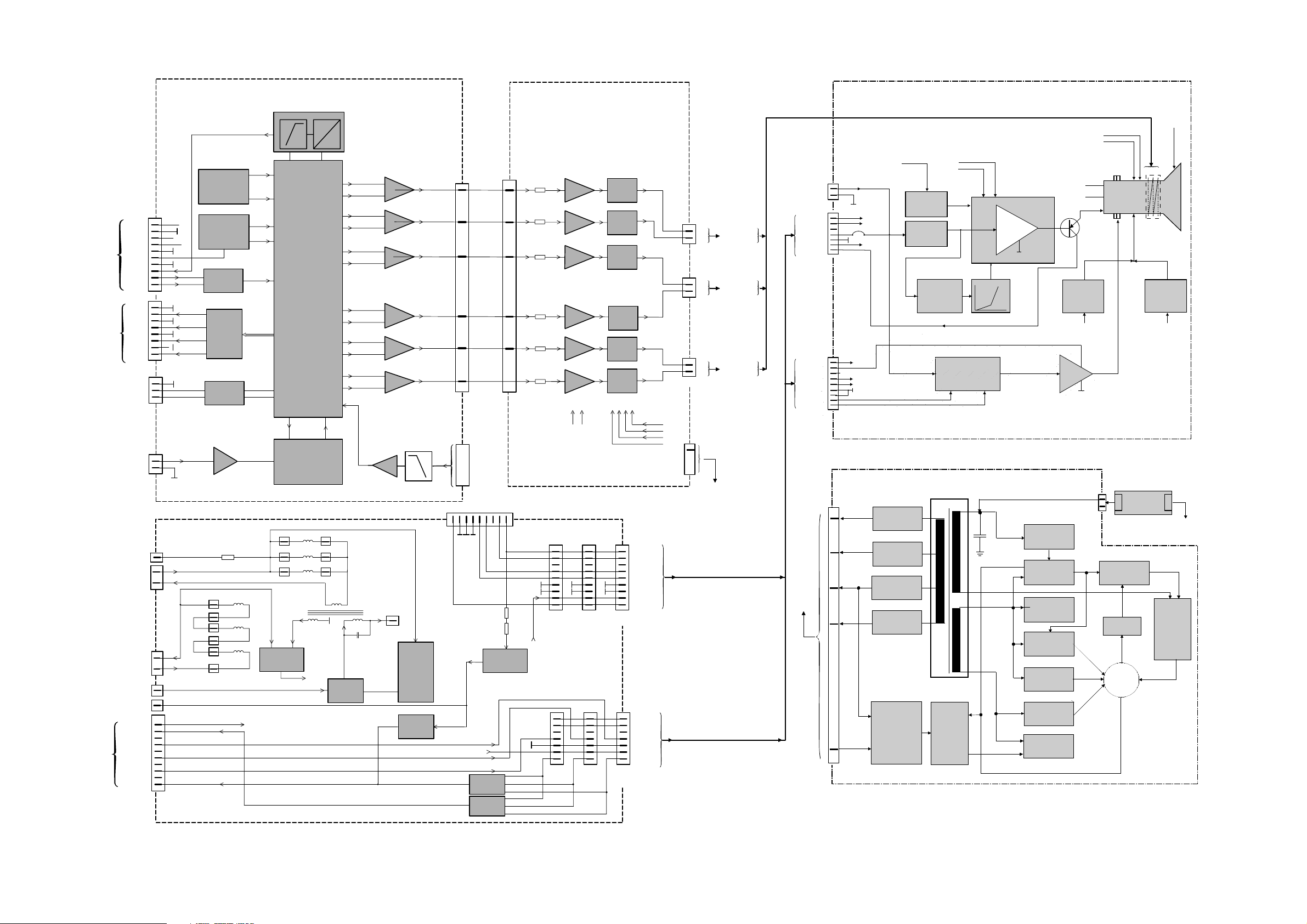
BLOCK DIAGRAM - SCHEMA SYNOPTIQUE - BLOCKSCHALTBILD - SCHEMA A BLOCCHI - ESQUEMA DE BLOQUES
Page 3
RP C21
First issue 09 / 01
BLOCK DIAGRAM - SCHEMA SYNOPTIQUE - BLOCKSCHALTBILD - SCHEMA A BLOCCHI - ESQUEMA DE BLOQUES
GND
R_GRID
GND
G_GRID
BUFFER
STAGE
TK20/TK22
TK24/TK25
SIGNAL
GENERATOR
IK01
STV2040
+13V -13V
BUFFER
DRV
IK03
DGV
SYNH
REST
SYNV
VIDR
VIDG
VIDB
VBLK
SCLS
SSDAI
GH
BV
DRH
GV
RH
BH
DGH
DBV
OPTT
OPT
LEVEL
RESULT
OPTI
PORT A/B/C
ORGA H/V
OPTI
BK16
BH
BV
GND
R_GRID
GND
FBTEXT
BK01
To Small signal Board
(BV010)
BK10
1
2
3
SCL
GND
SDA
1
2
3
4
5
6
7
8
DARV
DNRV
RV
DGV
DRV
DBH
GH
IK03
BUFFER
PRE
AMPL. RV
IA10
IG11
IG11
IB12
IB12
IA10
POW.
AMPL. RV
POW.
AMPL. RH
POW.
AMPL. GV
POW.
AMPL. GH
POW.
AMPL. BV
POW.
AMPL. BH
PRE
AMPL. RV
PRE
AMPL. GV
PRE
AMPL. GH
PRE
AMPL. BV
PRE
AMPL. BH
GND
To Photo Sensors
BS01
6
5
M
BR01
To Convergenve
deflection coil
red Picture Tube
To Convergenve
deflection coil
Green Picture Tube
To Convergenve
deflection coil
Blue Picture Tube
RVD
RHD
2
4
4
BG01
GVD
GHD
2
BB01
BVD
BHD
+15V
-15V
-53V
+53V
4
2
ABL1
GND_V
R_IN
R_IN
GND_V
BLK_CUR.
G_IN
G_IN
GND_V
B_IN
B_IN
GNDV
GNDV
BV05
1
2
3
4
5
6
7
8
9
10
VPR1
VSAW
BV13
BV12
V-PARA
BV17
V DEFLECTION COIL
H DEFLECTION COIL
BLUE
BLUE
DYF
GREEN
GREEN
RED
RED
1
1
2
2
4
5
678
3
4
5
6
7
8
9
BV02
BV01
From ICC20 BL200
From ICC20 BV300
From ICC20 BF001
From ICC20 BL035
1
2
3
4
5
6
7
8
9
9
BV04
U-VIDEO
U-VIDEO
U-VIDEO
From 10 BV05
USYS
USYS
HEAT H
HEAT H
HEAT L
HEAT L
GND
BSVM_BLANK
+20V
+20V
RV01
RV09
1
2
3
4
5
6
7
8
9
BV03
R
G
B
BSVM
ICUT
ABL1
BSVM_BLANK
1
2
2
1
2
1
1
3
3
G2ADJUST
V-PARA
GND
+6V
HFB
VSYN
V-RETRACE
H-RETRACE
V-PARA
MASTER
I2C
BUS
GND
+13V
-13V
GND
BK02
BK04
I
U
PS ADB ( BV12 )
1
2
3
4
5
6
7
8
9
HDEFL1
HDEFL2
H-FLYB
BV14
BV12
1
1
2
3
66
65
DAGV
49
DNGV
48
DAGV
64
DNGV
63
BUFFER
DRH
IK02
DBH
DBV
DARH
DNRH
IK02
BUFFER
IK02
BUFFER
52
51
DAGH
61
DNGH
H
DABV
H
DNBV
60
DABH
46
DNBH
45
RESET
13
2
1
69
68
SDAM
SCLM
DACF DNCF
3.3V
9
74 72
8
Grid signals
R, G, B, FB
GRID GENERATOR
SLAVE I2C BUS
SYNCHRONISATION
CONVERGENCE
DATA
STORAGE
VERTICAL CHANNELS
HORIZONTAL CHANNELS
IK08/IK15
POWER SUPPLY
TK09
IK05/TK26/TK27
LEVEL
CONVERTER
3.3V REGULATION
WATCHDOG
AND RESET
LEVEL
CONVERTER
TK47-TK48
IK02
IK02
IK02
IK02
IK02
IK03
IK03
COMPAR WITH
ADJUST LEVEL
ELECTRICAL STABILITY LOOP
FILTER AND COMPARATOR
TS36/TS39/TS41/TS48
I
U
DYNAMIC FOCUS
CONVERGENCE SIGNAL BOARD CSB
CONVERGENCE AMPLIFIER BOARD CAB
IK03
I
U
IS01/IS02/IS03
1
2
3
4
5
6
7
BV08
1
2
3
4
5
6
7
BV06
G2_ADJUST
+12V
V-GND
R-OUT
SLB
GND
1
2
3
4
5
6
7
BV07
B
R
G
B_IN
DCR_blue
DCR_green
DCR_red
G_IN
SLB
From Scal loss circuit
R_IN
DV20/21/22
TV20
PEAK LIMITER
VIDEO SIGNAL SPLITTER
DEFLECTION SPLITTER
VIDEO VOLTAGE SPLITTER
TV30...35
SUMM.
DV23/24/25
BV17
BV16
BV16
BV15
BV15
BV17
LV80
BV16
BV15
BV15
BV16
BV17
3
4
4
4
BV18
DYN. FOK.
RP SAFETY
TV80
+1KV
GENERATOR
DV85 - DV86
RV85
SCAN LOSS
BLANKING CIRCUIT
TV50/51/52
SLB
To 6/BV08
+250V SUPPLY
CURRENT LIMITER
TV01-TV04
RP SAFETY
TV01 - TV03
BEAM CURRENT
LIMITER
BSVM_BLANK (To 8/BV03-BV04)
ADAPTER BOARD
DGH
IK02
BUFFER
To CRT BBX03
(R, G, B)
To CRT BBX01
(R, G, B)
1
1
9
1
7
BBX02
BBX03
BP260
Signal Input
U Video
EHT
Focus
CONV
G2
G1
BSVM
COIL
Signal Input
S.L.B
S.L.B
DCR
S.L.B
G2-Adjust G2-Adjust
+20V
+20V
+12V
BSVM Blanking
G2 Adjust.
+USYS
Heater-High
Heater-High
Heater-Low
Heater-Low
+USYS
UVIDEO
UVIDEO
+USYS
+12V
V-GND
V-GND
BBX01
VIDEO AMP.
TDA 6120
SCAN LOSS
BLANKING
VIDEO
DELAY
BLACK LEVEL
TRA CKING
SPOT
KILLER
DIFFERENTIATION
G2
ALIGN
CRT BOARD
BSVM PART
PS RP21
Heater-High
Heater-Low
-53V
-15V
+15V
+53V
Secondary-
regulation
Optocoupler
SMT17
Overvoltageprotection
Frosincontrol
t_oncontrol
Foldbackcircuit
Softstart
PP RP21
BP210
BP001
Switch-ON
Start-UP
Drivercircuit
Powerstage
+
Switch-OFF
circuit
BP010
+
MIS
ON/OFF
CAB BW04
BP260 PS RP21
BW04
Page 4
RP C21
First issue 09 / 01
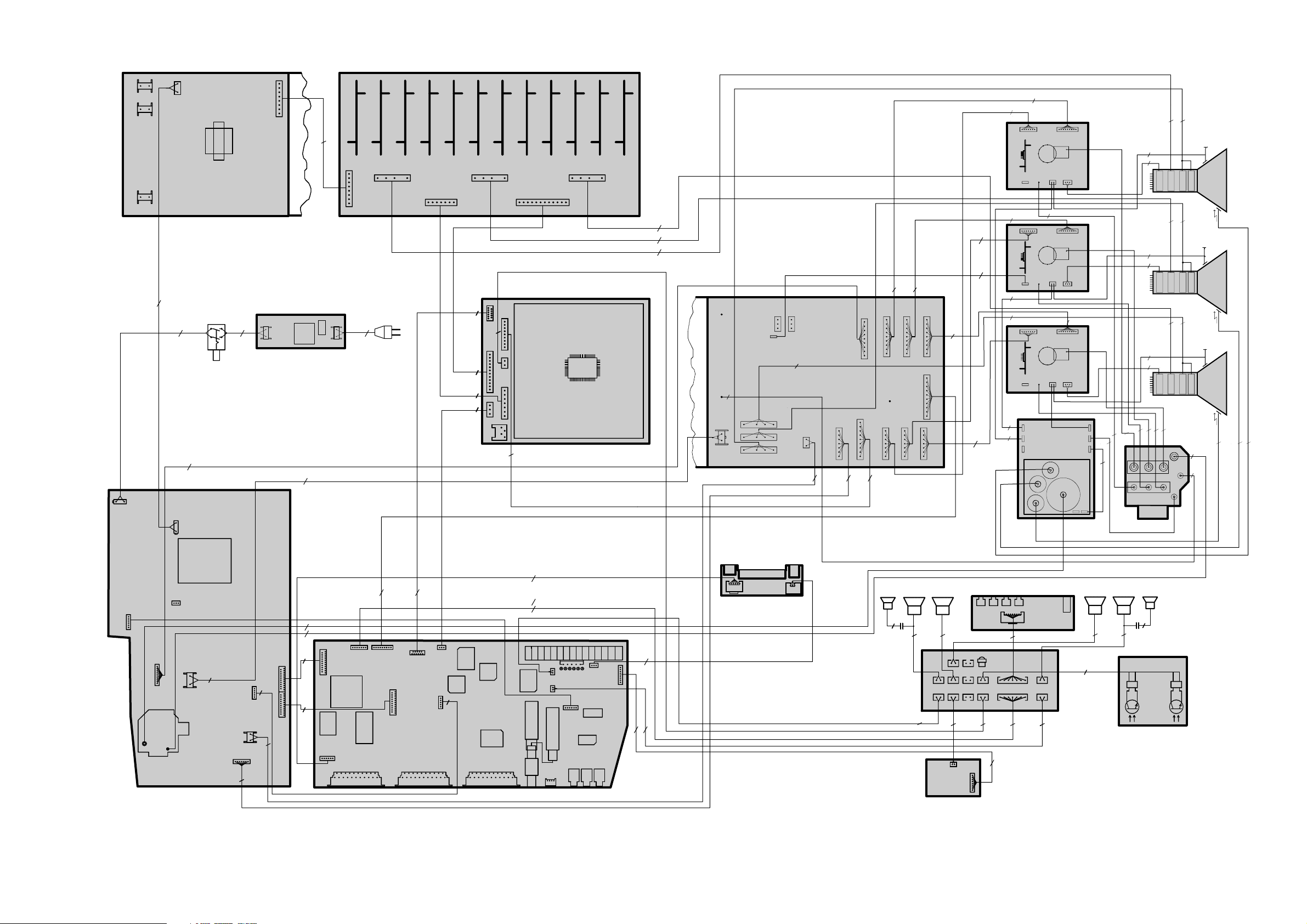
WIRING DIAGRAM - SCHEMA D’INTERCONNEXIONS - VERDRAHTUNGSPLAN - DIAGRAMMA DELLE INTERCONNESSIONI - ESQUEMA DE INTERCONEXIONES
200
2
1
1
10
11
6
4
7
3
28
395
7
2
5
5
21
21
focus
EHT
LL008
BP150
RP only
RP Convergern
(Gemstar Mod.VGA)
SSB 21000 00
BV010
BR002
BV300
BR001
BP500
IR001
IR110
IR130
BX004
BV001
BP501
IU002
IU003
IU030
IC700
BA005
NH500
BA010
BA019
BA017
BA018
IA001
IA180
BA012
1
1
1
1
1
1
1
1
1
1
1
1
1
1
1
1
1
1
BA009
BA007
BP010
BP130
BP120
BX100
BX200
1
1
1
1
1
1
1
1
1
1
1
1
1
BP001
LP050
BL035
BP005
BL111
BF001
BL200
BL500
NH001
BX300
BX001
IA002
2
BR01
BB01
CONVERGENCE SIGNAL
BOARD
CSB
POWER SUPPLY
PS
CAB
CONVERGENCE AMPLIFIER BOARD
11
12
7
9
220
8
2
2
9
2
2
2
3
SWITCH
MAINS
BK10
BK16
BK04
BK02
BK11
BS01
BK01
STV2050
BW05
BW16
BG01
ADAPTER SECTION
BP201
BP210
BP202
BP203
BP260
BW04
1
ADAPTER BOARD
ADB
RED
GREEN
BV23
1
1
111
1
Carrier
Carrier
Carrier
GND
GND
GND
99
1
4
4
4
4
44
1
1
4
7
7
9
1
9
9
2
2
2
111
1
1
1
1
1
1
1
4
1
BV01 BV03 BV04
BV02
BV05
BV96
BV07BV08
BV12
BV11
BV13
BV15
BV16
BV17
BV14
BV18
BV10
BV09
BV20
BV19
EHT
SPLITTER
B
G
R
EHT
Power Supply section
FOCUS
GRID2
FOC INP
FOC.
DYN.
GND
R
G
B
FOCUS BLOCK
BG103
BB151
BB170
BB158
BB103
BB101
CRTR
BG303
BB351
BB370
BB358
BB303
BB301
CRTG
CRT
B
BG203
BB251
BB270
BB258
BB203
BB201
FOC
FOC
FOC
CRT
CRT
CRT
CRT BOARD
CRT BOARD
CRT BOARD
BLUE
BSVM
BSVM
BSVM
Conv.
Conv.
Conv.
Vert.
Vert.
Vert.
Horiz.
Horiz.
Horiz.
TUBE
TUBE
TUBE
PICTURE
PICTURE
PICTURE
OF
:
KDB21XXX
7
7
PA/SW 20000 00
KEYBOARD
2
8 Sensor Autoconvergence*
*
* No Inserted in
some models
.......8x......
335
IR2100
GK01
BA09
BA10
BK02
BK01
BS01
BA06
BA03
BA01
BS02BA07BA04BA02
BA08
SK004
SK003
SK002
SK001
BA05
2
2
2
2
2
2
22
bass boomer
bass
boomer
2
2
RIGHT
LEFT
BA400
BA401
BQ012
BJ011
BQ009
BJ004
BJ010
FCB MODULE
1
1
GE001
BK001
A1
BP401
BP402
MIS 21000
27
7
7
1
9
8
4
4
4
PSB 21000 00
Page 5
RP C21
First issue 09 / 01
FRONT CONNECTOR BOARD - PRISES EN FACADE ET INTERCONNEXION DU
CLAVIER -FRONT ANSCHLUSSPLATTE - PIASTRA CONNESSIONE FRONTALE -
PLÁTINA MANDOS FRONTAL
FCB.21000.00
BJ011
1
2
3
4
5
BQ012
1
2
3
4
5
7
8
1
2
3
BJ010
1
2
3
4
5
6
4K7
LJ001
BJ004
BQ009
BA009
BX004
1
2
3
4
5
6
22N0
CQ003
22N0
CQ004
47R0
RQ006
47R0
RQ005
220P0
CJ003
220P0
CJ004
4K7
LJ002
GNDAU-
SIGNAL BOARD
AP.21XXX.00
FE.21XXX.00
VIDEO
FCB-GND
CHROMA
L
GNDV-
R
L
R
R
L
AUDIO
VIDEO
CHROMA.
VIDEO
FCB.21000.00
FCB
10710450/L1
FCB 21000 00
LJ001
LJ002
BQ009
1
BJ010
CJ004
CJ003
CQ003
CQ004
BJ004
1
BQ012
RQ005
RQ006
BJ011
JJ001
10710450/L1
FCB 21000 00
10710450.00.L1
2
13
BQ012
BQ009
BJ010
BJ004
4
2
5
1
3
BJ011
CAD-REF:
J
H
G
F
Page 6

RP C21
First issue 09 / 01
KB.21000.00
LU5351-JM
GE101
1
2
3
SK101
SK104
SK103
SK102
1
2
3
1
3
1
3
1
3
4
2
4
2
4
2
4
TSOP1333
GK101
1
2
3
BK101
1
2
3
4
5
6
7
22U0
CK102
3K32
RK104
100R0
RE102
453R0
RK101
681R0
RK102
1K5
RK103
1K0
RK105
270R0
RK106
3V3_UP
50.0V
KEYB
LED_R
LED_G
Vol-
Vol+
PR+
PR-
IR
5V_UP
RG
A2
A1
C
GND
OUT
Vss
KB.21000.00
KB
10710460/L1
KB 21000
RK101
RK105
RK102
RK106
RE102
RK103
RK104
CK102
BK101
1
GK101
SK103
SK102
SK104
SK101
GE101
C
A
B
C
D
E
V
Z
10710460/L1
KB 21000
CAD.REF:10710460.00.L1
Vol-
SK103
PR-
SK101
VOL+
PR+
BK101
SK102
SK104
GK101
GE101
E
D
C
B
A
Z
V
Page 7
RP C21
First issue 09 / 01
+10V
CP556
470U0
CP543
220N0
220N0
CP503
220N0
CP513
220N0
CP533
220N0
CP555
CP521
220N0
DP510
LL4148
DP540
LL4148
10K0
RP540
CP550
220N0
DP501
LL4148
DP521
LL4148
DP530
LL4148
PO
DEGAUSS
CP511
220N0
3
OUT
IN
GND
1
2
KF80BDT
IP510
OUT
3
2
1
KF80BDT
IP501
1V8_STBY
OUT
IN
IN
2
GND
GND
1
3
IP540
LF85CDT
RP530
3K3
4K7
RP521
CC524
100N0
D
TP520
STD17NF03L
CP527
220N0
CP544
100U0
CP504
100U0
CP514
100U0
3V3
470U0
CP534
1
1
10
11
12
13
14
15
16
17
18
19
2
20
3
4
5
6
7
8
9
21
21
BP500
BP005
10N0
CP560
ECO_STANDBY
10N0
CP561
CP562
CP565
CP571CP569
10N0
CP570
10N0
1K0
RP524
AQR_ON_
JP551
MP40
MP40
FP500
FP551
GND
OUT
IN
3
2
1
LD1117DT33
IP530
2
GND
3
OUT
1
IN
LF18ABDT
IP551
FP520
MP100
MP100
FP521
ZMM10
DP520
RP520
4K7
470U0
CP525
220N0
CP523
1K0
RP523
22R0
RP527
+6V
6
5
3
2
1
4
BC847BS
TP523
1
1
2
3
4
5
5
BP501
BP150
RP522
470R0
RP525
1K0
220U0
CP512
220U0
CP522
CP563
10N0
CP564
10N0
10N0
10N010N0
RP526
470R0
INF_POW_FAIL
REF
5V_STBY
SAFETY
SPP.21000.00
G
S
33V
DEGAUSS
PO
AQR_ON
5V_STBY
SAFETY
20V
ECO_STANDBY
INF_POW_FAIL
SSB
POWER BOARD
(PSB)
POWER SUPPLY PART
!
!
RP560
120K0
!
!
(0.5 ): STBY)
(3.45): ECO
0.5
(5)
(5)
8.5 : DC VOLTAGE TV ON
(9.2) : DC VOLTAGE TV Standby
40V
3V3_STBY
20V
+10V
+6V
+10V
+6V
20V
5V_STBY
5V_STBY
8V5
8V_1H
3V3_STBY
33V
8V5
8V_1H
8V_2H
8V_2H
5V_A
5V_A
5V_V
5V_V
8.5
8.5
8
8
8
8
5
5
6.4
6.4
6.4
6.4
21.4
3.3
3.3
34
1.8
6.4
6.4
11.7
11.7
11.7
11.7
(3.45)
SMALL SIGNAL BOARD - PLATINE PETITS SIGNAUX - SIGNAL-PLATINE - PIASTRA PICCOLI SEGNALI - PLACA PEQUEÑA SEÑAL
SIGNAL BOARD POWER PART - PARTIE ALIMENTATION DE LA PLATINE PETITES SIGNAUX - BETRIEBSSPANNUNGSERZEUGUNG SIGNAL PLATINE PARTE ALIMENTAZIOEN PIASTRA SEGNALI - PARTE ALIMENTACIÓN PLACA SEÑAL
Page 8
RP C21
First issue 09 / 01
SMALL SIGNAL BOARD - PLATINE PETITS SIGNAUX - SIGNAL-PLATINE - PIASTRA PICCOLI SEGNALI - PLACA PEQUEÑA SEÑAL
REMOTE / MICROCONTROLLER - GESTION / MICROCONTROLEUR - FERNBEDIENUNGS- UND MICROCONTR O LLERSTUFEN - MICROPROCESSORE - REMOTO / MICROCONTROLADOR
ROMCS0_
ROMCS1_
0
0
0
0
0
0
80R
0
(UC) UC_V
OSD_FSW
JTOUT
JTCLK
JTSEL
EXT_VSS9
EXT_VDD9
PWM3
MOSI
MISO
SPISSB
SPISCK
TMROUT
RESET_
SYNCDET0
SYNCDET1
CORE_VSS2
GPIO(23)
EXT_INT(2)
CORE_VSS1
CORE_VDD1
ADDR(1)
DATA(15)
EXT_VSS4
DATA(13)
DATA(12)
DATA(11)
DATA(10)
DATA( 9)
DATA( 8)
DATA( 7)
DATA( 6)
DATA( 5)
DATA( 3)
CORE_VSS0
CORE_VDD0
DATA( 2)
DATA( 1)
DATA( 0)
HBE
SRAMCS_
OE_
EXT_VSS2
EXT_VDD2
WE_
ROMCS1_
ROMCS0_
SDA10
SDWE_
SDCAS
SDRAS
SDCS1_
EXT_VSS1
SDCLK
EXT_VDD1
SDCKE
SDCS0_
DATA( 4)
EXT_VDD3
EXT_VSS3
DATA(14)
ADDR(0)
ADDR(2)
ADDR(3)
ADDR(4)
ADDR(5)
ADDR(6)
ADDR(7)
EXT_VDD4
ADDR(8)
ADDR(9)
ADDR(10)
ADDR(11)
ADDR(12)
ADDR(13)
ADDR(14)
ADDR(15)
ADDR(16)
ADDR(17)
EXT_VDD5
EXT_VSS5
EXT_VDD6
EXT_VSS6
ADDR(18)
ADDR(19)
ADDR(20)
ADDR(21)
ADDR(22)
ADDR(23)
EXT_5VTOL
I2CDAT(0)
I2CCLK(0)
EXT_INT(0)
IROUT
IRIN
EXT_INT(1)
EXT_INT(3)
HSYNC
VSYNC
I2CDAT(1)
I2CCLK(1)
GPIO(10)
SDIN
SDOUT
GPIO(13)
EXT_VSS5_0
SIRIN
SDOUT
PWMO0
PWMO1
GPIO(20)
GPIO(21)
GPIO(22)
CORE_VDD2
I2CCLK2
I2CDAT2
I2CCLK3
I2CDAT3
EXT_VSS8
EXT_VDD8
PWM2
EXT_VDD5_1
JTIN
PLLBYPASS
GPIO(35)
PLLB_AVCC
PLLB_AGND
PLLB_DGND
PLLB_DVCC
ANA_G_PWR
ADC_REFN
ADCIN4
ADCIN3
ADCIN2
ADCIN1
ADCIN0
AVSS
AVDD
CCVIDEO
OSDDACVSS
OSDDACVDD
OSD_R
OSD_G
OSD_B
ADCVD3
ADCVS3
TTVIDEO
ADCREFM
ADCREFP
ADCVS2
ADCVD2
ADCVS1
ADCVD1
PLLA_AVCC
PLLA_AGND
PLLA_DGND
PLLA_DVCC
CORE_VDD3
OSCIN
OSCOUT
CORE_VSS3
CR075
47N0
100P0
CR071
100P0
CR070
3K3
RR070
3K3
RR071
220R0
RR072
220R0
RR075
100R0
RR081
39P0CR081
39P0
CR082
47N0
CR085
RR080
100R0
CR083
47N0
RR082
10K0
39P0
CR001
CR002
39P0
1K0
RR050
RR005
1K5
TR060
BCR141
39P0
CR057
100P0
CR159
CR160
100P0
CR172
100P0
3K3
RR182
47K0
RR183
47K0
RR184
CR181
47P0
CR183
100P0
100P0
CR184
10K0
RR111
1K0
RR112
IIC_DA_2
IIC_CL_2
E0
E1
E2
VSS
5
SDA6SCL8VCC
7
WC
432
1
M24C64MN6
IR005
4K7
RR046
100N0
CR038
100U0
CR066
CR065
100U0
100U0
CR067
RR102
4K7
IIC_DA_2
IIC_CL_2
1
1
2
3
4
8
7
6
5
4
BR011
RR045
4K7
(FE) CVBS_TXT
(FE) AV1_PIN8
(FE) AV2_PIN8
IIC_DA_1
RR056
RR187
10K0
4K7
1
2
3
BR002
to RP
2
3
BR008
To SUB OSD BX001
39P0
CR007
3K3
RR181
KEYBOARD
KEYBOARD
150R0
RR026
RESET_
CR011
3N9
820P0
CR012
CR041
3N9
100N0
CR015
CR031
3N9
100N0
CR039
CR050
100N0
3N9
CR051
CR027
820P0
CR026
3N9
CR025
100N0
CR100
10N0
47N0
CR008
CR010
100N0
1N0
CR006
CR032
820P0
KEYBOARD
RR191
4K7
LR025
240R0
LR027
LR052
LR043
LR026
3N9
CR016
RR113
1K0
1K0
RR114
RR115
1K0
RR116
1K0
RR119
3K65
RR120
3K65
3K3
RR159
RR160
3K3
RR172
47K
10K0
RR198
CR003
CR005
220N0
220P0
IIC_CL_3
1K5
RR069
RR064
10K0
(PP) INF_POW_FAIL
TR062
RR061
100R0
BC846B
100K0
RR068
TR061
BC856B
1K0
RR066
CR068
10N0
RR067
1K0
RR065
8K2
CR009
47N0
27R0
RR025
TR015
BC856B
1K5
RR015
CR030
100N0
1
2
3
4
5
6
7
8
9
10
11
1
2
3
4
5
6
7
8
9
10
11
BR006
To DVB (ICC23)
470R0
RR063
56K0
RR117
LR066
0
10K0
RR101
IIC_CL_1
LED
(PP)
(VP) PO_TR
LED
MOSI
MISO
SPISSB
SPISCK
18K0
RR118
1M0
RR006
RR100
10K0
RR103
10K0
8M0
QR001
1
2
3
4
5
6
7
BR001
BK001
6
5
4
3
2
1
BR004
BW004
JTSEL
JTCLK
JTOUT
JTIN
WE_ROM_
JTAG
IRDA_IN
IRDA_OUT
RR044
4K7
65432
1
BR007
LR017
47K0
RR012
RR011
47K0
47K0
RR013
RR062
1K0
(AP) MASTER_MUTE_
CR060
1N0
820P0
CR042
CR052
820P0
LR051
3N9
CR021
CR022
820P0
LR020
100N0
CR020
100N0
CR040
JR081
JR080
0
0
LR012
47K0
RR016
LR041
LR016
(FE) FB2_FORCE
(FE) FB1_FORCE
(AP) MASTER_MUTE
(VP,DP) TUBE_DETECTION
IR
RR051
1K0
TR198
RR199
100R0
BC846B
PO
CR190
10N0
RR185
JR041
JR046
0
0
4K7
1
VDD
2
DATAOUT
3
DATAI N
4
CLOCK
5
RESETN
6
ADDR3N
7
ADDR2N
8
GND
9
A0
10
A1
11
A2
12
A3
16
A7
13
A4
15
A6
A5
14
TCE2ACU
IR006
6
5
432
1
BR005=>
DVD (PD21000)
IR_OUT
IR
(AP) RESET_AUDIO
IIC_CL_4
IIC_DA_4
(FE) AV_PIN8_OUT
(UC) UC_H
(FE) FB1_DET
(FE) FP_DET
RESTART
(PP) EFC
(PP) AQR_ON
(UC) IIC_DA_3
(UC) IIC_CL_3
(AP,VP,FE) IIC_DA_2
(AP,VP,FE ) IIC_CL_2
UART_IN
CR017
820P0
10K0
RR158
(FE) FB2_DET
CS_SPI
RESET_
(FE) AV_LINK
1K0
RR190
LR065
0
OUT
4
GND
2IN21
MC33460SQ/
-30ATR
IR004
4
3
2
1
5
6
7
8
5
6
7
8
5
6
7
8
5
6
7
8
5
6
7
8
5
6
7
8
100R0
RR320
4
3
2
1
5
6
7
8
1
2
3
4
100R0
RR340
GND
GND
CR500
1N0
4
3
2
1
100R0
RR321
4
3
2
1
5
6
7
8
100R0
RR326
4
3
2
1
5
6
7
8
100R0
RR327
123
4
5
6
7
8
RR329
100R0
UART_IN
UART_OUT
DVD_ON
(VP) G2_ADJUST
4
3
2
1
5
6
7
8
4
3
2
1
RR341
100R0
(FE) RGB_AV_SELECT
(FE) FB_CLEAR
(FE) TAK_FB
(PP) DEGAUSS
RR009
10K0
IIC_DA_3
CS_SPI
IR_OUT
47N0
CR150
JR140
LR067
0
4K7
RR157
CR182
47P0
LR030
0
LR047
LR046
LR045
LR044
LR015
240R0
240R0
RR163
4K7
47K0
RR161
4
3
2
1
100R0
RR325
4
3
2
1
100R0
RR324
ON
(VP) SAFETY_ENABLE
4
3
2
1
100R0
RR323
4
3
2
1
100R0
RR322
80R0
80R
80R0
0
0
0
4
3
2
1
5
6
7
8
RR328
RR196
47K0
RR195 47K0
RR194 47K0
100R0
LR010
240R0
SDCS0__
SDCS1
1
2
3
4
5
6
7
8
9
10
11
12
13
14
15
16
17
18
19
20
21
22
23
24
25
26
27
28
29
30
504948474645444342
41
40
39
38
37
36
35
34
33
32
31
5152535455565758596061626364656667686970717273747576777879
80
99
98
97
96
95
94
93
92
91
90
89
88
87
86
85
84
83
82
81
121
122
123
124
125
126
127
128
129
130
131
132
133
134
135
136
137
138
139
140
141
142
143
144
145
146
147
148
149
150
151
152
153
154
155
156
157
158
159
160
120
119
118
117
116
115
114
113
112
111
110
109
108
107
106
105
104
103
102
101
100
8079787776757473727170696867666564636261605958575655545352
51
414243444546474849
50
GENCAM CUT1.1
IR001
SDCKE
80R0
47K0
RR010
SDRAS
SDCAS
SDWE_
SDA10
WE_
OE_
LR001
120R0
LR011
RR001
100R0
SDCLK
4
3
2
1
5
6
7
8
RR302
100R0
D0
D1
D2
D3
4
3
2
1
5
6
7
8
100R0
RR303
D4
D5
D6
D7
4
3
2
1
5
6
7
8
RR304
100R0
D8
D9
D10
D11
4
3
2
1
5
6
7
8
100R0
RR305
D15
D14
D12
D13
4
3
2
1
5
6
7
8
RR306
100R0
LR022
LR021
80R0
LR042
123
4
567
8
RR307
100R0
876
5
432
1
100R0RR308
876
5
432
1
RR309 100R0
876
5
432
1
RR311 100R0
123
4
567
8
RR310
100R0
0
0
5
6
7
8
1
2
3
4
RR300
100R0
5
6
7
8
1
2
3
4
100R0
RR301
123
4
567
8
RR312 100R0
A0A1A2A3A4A5A6A7A9A8A10
A11
A12
A13
A14
A15
A16
A17
A18
A19
A20
A21
A22
A23
UART_OUT
CR004
RR003
220N0
RR004
47K0
47R0
1K0
RR180
39P0
CR170
39P0
CR171
RR170
1K8
1K8
RR171
WE_
3V3_UP
RR193
47K
3V3_UP
5V_V
RR250
CR250
470U0
CR251
3N9
+
33R0
3V3_UP
BP001
(VP)
470R0
RR135
470R0
RR145
TR144
BC856B
TR145
BC846B
470R0
RR137
470R0
RR147
(VP) G_OSD
(VP) R_OSD
RR136
470R0
1K2
RR146
BC846B
TR147
BC856B
TR146
470R0
RR139
RR138
470R0
1K2
RR148
BC846B
TR149
BC856B
TR148
RR134
470R0
FB_OSD
B_OSD
(VP)
RR142
10R0
470R0
RR141
RR140
3K9
RR144
1K2
RR130
470R0
470R0
RR131
470R0
RR149
TR141
BC846B
TR140
BC856B
RP.21000.00
(RP) REMOTE PART
SSB
3V3_STBY
5V_UP
5V_UP
5V_UP
5V_V
5V_UP
1V8_UP
5V_UP
5V_UP
5V_UP
5V_UP
5V_UP
3V3_UP
3V3_STBY
3V3_STBY
3V3_STBY
5V_V
5V_UP
3V3_UP
3V3_UP
3V3_UP
3V3_UP
3V3_UP
3V3_UP
5V_UP
3V3_STBY
1V8_UP
5V_UP
3V3_UP
5V_V
3V3_STBY
5V_UP
3V3_STBY
3V3_STBY
5V_STBY
1V8_UP
(SPP) 1V8_STBY
(SPP) 5V_STBY
CS_SPI
VDFL
HDFL
UC_V
UC_H
(SPP) 5V_V
(SPP) 3V3_STBY
(PP) ECO_STANDBY
5V_UP
5V_UP
0.1
1.8
5V_UP
5V_V
5V_V
5V_V
5V_V
3V3_STBY
5V_V
TAK MODULE
Page 9
RP C21
First issue 09 / 01
0
3V3_ROM
VDD
A1
A2
A3
A4
A5
A6
A7
A17
A18
RY/BY
WP/ACC
A21
RESET
WE
A20
A19
A8
A9
A10
A11
A12
A13
A14
A15
VDD
DQ0
VDDQ
DQ1
DQ2
VSSQ
DQ3
DQ4
VDDQ
DQ6
DQ5
VSSQ
DQ7
DQML
WE#
CAS#
RAS#
CS#
BA0
BA1
A10
A0
A1
A2
A3
A15
ROM
A14
A13
A12
A11
A10
A9
A20
A21
WE_
A19
A18
A8
A7
A6
A5
A4
A2
0
JR122
Flash
SDRAM
A3
A16
CR116
3N9
CR117
820P0
100N0
CR115
100N0
CR110
3N9
CR111
LR110
240R0
CR112
820P0
100N0
CR120
3N9
CR121
820P0
CR122
LR120
240R0
CR130
100N0
LR130
240R0
D0
D1
D2
D3
D4
D5
D6
D7
A19
SDWE_
SDCAS
SDRAS
SDCS0_
A21
A22
SDA10
A0
A1
A2
A3
LR115
240R0
CR131
3N9
CR132
820P0
1
2
3
4
5
6
7
8
9
10
11
12
13
14
19
20
21
22
23
24
25
16
15
17
18
26
28
29
30
31
32
33
34
35
36
37
38
39
40
41
42
43
44
45
46
47
48
49
27
50
51
52
53
54
MT48LC4M16A2TG-8E
IR110
VDD
1
2
3
4
5
6
7
22
21
20
19
18
17
16
15
14
13
12
11
10
9
8
23
24
25
26
27
28
29
30
31
32
33
34
35
36
37
38
39
40
41
42
43
44
MX29L3211MC-10
IR130
A19
A18
A7
A8
A6
A5
A4
A3
A2
A1
OE_
D0
D8
D1
D9
D2
D10
D3
D11
LR121
1
2
3
4
6
7
24
23
22
21
20
19
18
17
16
15
14
13
12
11
10
9
8
25
26
27
28
29
30
31
32
33
34
35
36
37
38
39
40
41
42
43
44
45
46
47
48
5
IR120
NI
ROMCS0_
80R0
LR111
80R0
LR116
80R0
LR131
JR136
0
JR132
47K0
JR120
0
WE_ROM_
JR131
0
RESET_
JR124
0
VSS
A4
A5
A6
A7
A8
A9
A11
CKE
CLK
DQMH
NC
NC
DQ8
VDDQ
DQ9
DQ10
VSSQ
DQ11
DQ12
VDDQ
DQ13
DQ14
VSSQ
DQ15
VSS
VSS
A0
CE
VSS
OE
DQ0
DQ8
DQ1
DQ9
DQ2
DQ10
DQ3
DQ11
VDD
DQ4
DQ12
DQ5
DQ13
DQ6
DQ14
DQ7
A16
BYTE
VSS
DQ15/A-1
D15
D14
D13
D12
D10
D9
D8
A20
SDCLK
SDCKE
A11
A9
A8
A7
A6
A5
A4
D11
OE_
D0
D8
D9
D2
D10
D11
D4
D12
D5
D13
D6
D14
A17
D1
D3
D7
D15
A1
ROMCS1_
A17
A7
A6
A5
A4
A3
A2
A1
A0
CE
OE
Q0
Q8
Q1
Q9
Q2
Q10
Q3
WE
Q11
GND
A18
Q4
Q12
Q5
Q13
Q6
Q14
Q7
GND
A16
A15
A14
A13
A12
A11
A10
A9
A8
A19
VCC
A20
BYTE
Q15/A-1
D4
D12
D5
D13
D6
D14
D7
D15
A17
A16
A15
A14
A13
A12
A11
A10
A9
A20
A21
RP.21000.00
(RP) REMOTE PART
SSB
3V3_STBY
3V3_STBY
3V3_STBY
3V3_STBY
3V3_ROM
SMALL SIGNAL BOARD - PLATINE PETITS SIGNAUX - SIGNAL-PLATINE - PIASTRA PICCOLI SEGNALI - PLACA PEQUEÑA SEÑAL
SDRAM - FLASH MEMORY
Page 10
RP C21
First issue 09 / 01
SUB OSD MODULE - MODULE SUB OSD - OSD SUBMODUL - MODULO SUB OSD - MÓDULO SUB OSD
5V_V
1M0
RX023
JT_IN
AUSTAST_V
AUSTAST_H
VCCINT
H_IN
CLOCK
CLOCK_OUT
Q_OUT
GND
GND
GND
RESERVED
Q_IN
TDO
VCCIO
TCK
RESERVED
V_IN
VCCINT
GND
RESERVED
RESERVED
RESERVED
VCCI0
GND
TDI
JT_CLK
JT_SEL
RX002
220R0
100N0
CX010
100N0
CX020
1
1
1
TP02
TP03
TP04
1
TP05
1
TP06
100N0
CX024
1
TP01
CX001
100P0
CX004
100P0
CX003
100P0
100P0
CX002
CX022
100P0
680R0
RX022
TMS
GND
RESET
V_OUT
H_OUT
RESERVED
GND
GND
CX007
47U0
CX008
100N0
1
2
3
4
8
7
6
5
LE33CD
IX030
47N0
CX031
0
LX024
0
LX008
0
LX010
0
LX020
JT_OUT
132
QX022
4MHZ
100P0
CX005
RX005
220R0
100P0
CX021
RX030
680R0
1K0
RX017
1K0
RX032
1K0
RX036
1K0
RX038
100N0
CX030
RX001
220R0
LX002
LX007
RX003
220R0
220R0
RX004
CS_SPI
UC_V
VDFL
UC_H
HDFL
1
3
4
5
6
7
8
BX001
RESERVED
RESERVED
RESERVED
RESERVED
RESERVED
RESERVED
RESERVED
RESERVED
RESERVED
RESERVED
RESERVED
1
2
3
4
6
7
5
8
9
10
11
22
21
20
19
18
17
16
15
14
13
12
23
24
25
26
27
28
29
30
32
33
31
4443424140393837363534
IX010
EPM3032ATC44-10
SUB OSD 21000 00
OSD
3V3_V
3V3_V
3V3_V
3V3_VPLD
3V3_VPLD
3V3_VPLD
3V3_V
3V3_VPLD
3V3_V
5V_V
3V3_V
5V_V
RP.21000 PART
BR008
SMALL SIGNAL BOARD
82
7
5
4
1
2
6
3
RX001
RX038
RX036
BX001
RX004
RX003
CX004
CX002
LX010
CX010
CX003
RX005
CX005
RX039
LX008
RX017
IX010
LX002
RX002
CX020
RX037
1
CX008
LX020
CX007
RX018
1
QX022
+
LX007
CX030
1
RX032
IX030
LX024
CX024
CX031
CX019
CX001
RX033
RX024
CX022
RX022
RX023
CX021
RX030
LX008
RX017
LX002
1
RX002
IX010
CX020
RX037
CX008
LX020
CX007
RX018
1
QX022
+
LX007
CX030
1
RX032
IX030
LX024
CX024
CX031
CX001
RX024
RX022
RX023
RX030
CX019
RX033
CX022
CX021
RX001
RX038
RX036
BX001
RX004
RX003
CX004
CX002
LX010
CX010
CX003
RX005
CX005
RX039
SUB OSD 21000
SUB OSD 21000
Page 11

CONVERGENCE SIGNAL BOARD - PLATINE DES SIGNAUX DE CONVERGENCE - KONVERGENZSIGNAL-PLATINE - PIASTRA SEGALI CONVERGENZA PLACA SEÑAL CONVERGENCIAS
(1-BK04)
2Vpp-V
DRH
DGH
1,7Vpp-H
1Vpp-H
0
0
32
µs
DBH
2.5pp-H
0
0
DRV
10ms
(2-BK04)
2Vpp-V
0
DGV
32
µs
DBV
2.2Vpp-V
10ms
0
0
0
32
µs
0
0
32
µs
+
-
-
+
-
+
-
++
-
+
-
+
-
+
-
+
-
+
-
+
-
+
-
+
-
+
-
1K0
RS32
4K7
RS33
10K0
RK50
1K0
RK59
47R0
RS40
1K0
RK32
1K0
RK31
1K0
RK30
100R0
RK45
100R0
RK46
100R0
RK27
100R0
RK26
100R0
RK22
4K7
RK99
1K3
RS08
1K82
RS09
10K0
RS11
10K0
RS12
10K0
RS13
2K43
RK64
3K3
RK87
470R0
RK86
4K7
RK03
4K7
RK02
100R0
RK48
100R0
RK47
100R0
RK07
10K0
RS50
2K43
RK70
374R0
RK12
374R0
RK11
8K2
RK56
470R0
RK06
2K43
RK68
374R0
RK20
374R0
RK14
2K43
RK66
2K43
RK60
2K43
RK62
374R0
RK09
374R0
RK15
374R0
RK13
2K7
RK85
15K0
RK01
1K0
RK93
100R0
RK28
10K0
RK88
2K2
RK44
22K0
RK95
324R0
RK39
1K0
RK10
100R0
RS37
1K0
RS06
1K0
RS05
1K0
RS03
1K0
RS02
1K0
RS04
1K0
RS01
324R0
RK42
324R0
RK40
1K0
RK25
324R0
RK35
324R0
RK36
324R0
RK37
324R0
RK41
15K0
RK04
82K0
RK52
10K0
RK24
560R0
RS45
1K0
RS47
2K2
RS39
4K7
RS36
560R0
RS46
1K5
RS48
470R0
RK72
3K3
RS42
220R0
RS41
47K0
RS34
100R0
RS15
680R0
RS51
220R0
RS30
*No cnnected
in some models
47K0
RS54
2K7
RS52
1K0
RK33
470R0
RS31
10K0
RK54
10K0
RK53
2N7
CS06
2N7
CS05
2N7
CS04
2N7
CS01
2N7
CS02
2N7
CS03
100N0
CK76
LL4148
DK08
LL4148
DK10
LD1117DT33C
IK05
312
680P0
CK44
680P0
CK45
1U0
CS53
3N3
CS52
1N0
CK10
47P0
CK07
100N0
CK20
100N0
CK65
680P0
CK35
1N0
CK66
2N2
CK12
100N0
CK08
100N0
CK60
100N0
CK14
10N0
CK31
680P0
CK39
680P0
CK38
100N0
CK32
100N0
CK36
680P0
CK33
680P0
CK34
100N0
CK42
100N0
CK37
1N5
CK04
10N0
CK03
100N0
CK09
100N0
CK02
100N0
CK01
680P0
CK41
100N0
CK06
100N0
CK16
100N0
CK11
1N0
CK63
1N0
CK64
100N0
CK05
100N0
CK15
100P0
CK17
10N0
CK18
15N0
CK26
33P0
CK50
100N0
CS45
220N0
CS46
100N0
CK21
220N0
CS50
680P0
CK43
680P0
CK46
680P0
CK47
680P0
CK48
100N0
CK55
100N0
CK54
BC857C
TK09
BC857C
TK27
BC857C
TK26
BC857C
TS48
M24164-WMN6
IK08
1
2
3
4
5
6
7
8
M24C32WMN1
IK07
1
2
3
4
5
6
7
8
NI
IK15
1
2
3
45
6
7
8
STV2050A
IK01
123456789101112131415161718192021222324
252627282930313233343536373839
40
41 42 43 44 45 46 47 48 49 50 51 52 53 54 55 56 57 58 59 60 61 62 63 64
65
66
67
68
69
70
71
72
73
74
75
76
77
78
79
80
BC847C
TK24
BC847C
TK22
BC847C
TK20
BC847C
TK14
BC847C
TS39
BC847C
TS36
BC847C
TS41
BC847C
TK04
BC847C
TK25
BC847C
TS50
10U0
CK23
10U0
CK53
10U0
CK24
10U0
CK25
10U0
CK67
220U0
CK72
220U0
CK70
100U0
CK75
10U0
CK71
1U0
CK40
BZX85C3V9
DK09
BS01
*IR2101
1
2
10U0
LK15
1U0
LK03
1U0
LK10
1U0LK12
1U0LK13
1U0
LK02
1U0
LK04
1U0
LK06
10U0
LK19
10U0
LK17
10U0
LK16
1U0
LK07
1U0
LK05
1U0LK14
1U0LK11
10U0
LK08
10U0
LK01
1U0
LK09
10U0
LK18
LM393D
IS02
6
5
7
8
4
LM393D
IS01
6
5
7
8
4
LM393D
IS02
2
3
1
8
4
LM393D
IS03
2
3
1
8
4
LM393D
IS01
2
3
1
8
4
LM393D
IS03
6
5
7
8
4
1
2
3
BK15
123
1
2
3
4
5
6
7
1
2
3
4
5
6
7
8
9
10
11
12
1
2
3
4
5
6
7
8
9
TL084CD
IK03
13
12
14
4
11
TL084CD
IK02
2
3
1
4
11
TL084CD
IK03
9
10
8
4
11
TL084CD
IK03
6
5
7
4
11
TL084CD
IK02
13
12
14
4
11
TL084CD
IK02
6
5
7
4
11
TL084CD
IK02
9
10
8
4
11
TL084CD
IK03
2
3
1
4
11
1
2
3
4
5
6
7
8
9
10
11
BK11
1
2
3
BSN20
TK47
BSN20
TK48
BK21
BK20
VSYN VSYN
VSYN
-13V
RH
GH
R_GRID
BH
BLUEFILT
PORTB
PORTB
GV
G2_ADJ
G2_ADJ
OGAH
OGAH
SCL
SCL
LFGH
LFBH
PORTA
PORTA
BV
LFGV
LFBV
PORTC
PORTC
RV
SDA
SDA
FBTXT
LFRV
+6V +6V
OPTI
OPTI
VPARA
VPARA
VPARA
HFB HFB
HFB
B_GRID
G_GRID
OPTT
OPTT
G2ADJUST
OGAV
OGAV
GND
GND
GND
GND
GND
GND
GND
GND
GND
GND
GND
GND
GNDL
GNDL
GNDL
GNDL
GNDL
GNDL
GNDL
GNDL
GNDL
GNDL
GNDL
GNDL
GNDL
GNDL
GNDL
+13V
GNDA GNDAGNDA
GNDA
GNDA
GNDA
GNDAGNDAGNDA
GNDA
GNDA
GNDA
GNDA
GNDA
GNDA
GNDA
GNDA
GNDA
GNDA
GNDA
GNDA
GNDA GNDA GNDA GNDA GNDA GNDA
GNDA
GNDA
GNDA
GNDAGNDA
GNDA GNDA
GNDAGNDA
GNDAGNDA
GNDA
GNDA
GNDA
only lab use
PHOTO
SENSORS
M
S
S
S
S
S
S
M
PORA
SDAM
GNDC
DNCF
DACF
VCCC
ADSO
OPTI
VCCM
OPTT
MLIN
GNDM
POUT
PORC
PORB
DARV
DNRV
DAGV
DNGV
VCCB
DABV
DNBV
GNDB
OGAV
OGAH
GNDP
REFC
REFN
GNDI
DARH
DNRH
VCCA
DAGH
DNGH
GNDA
TBU1
VCCH
TBU0
VCCF
GNDF
GNDH
DABH
DNBH
VCCG
GNDG
TBU2
TBU3
TBU4
TBU5
TBU6
TBU7
VCCL
VCCJ
GNDL
GNDJ
SYNV
SYNH
FIL1
FILT
GRES
OSCL
GNDD
VCCD
VIDB
VIDG
VIDR
GNDN
ECLK
REST
VCCN
TEST
VBLK
SCLS
VCCK
VCCQ
GNDK
GNDQ
SCLM
SDAO
SDAI
DBV
DGV
DRV
D
C
B
DBH
DGH
DRH
DYFV
D
C
B
A
to ADB
MEMORY
MEMORY
A
S2
S1
S0
SDA
SCL
TEST
VCC
VSS
S2
S1
S0
SDA
SCL
TEST
VCC
VSS
S2
S1
S0
SDA
SCL
TEST
VCC
VSS
BK16
1
7
BK04
12
POWER AMPLIFIER
TO CONVERGENCE
TO CONVERGENCE
POWER AMPLIFIER
TO CONVERGENCE
BW05
1
BW16
BK10
BR002
ADB
SSB
BK02
BV12
BK01
BV010
ALIGNNERT
FOR PRODUCTION
(CSB).RP21.00
and Ik03 can damage IK01
Measurements around IK02
ATTENTION! *
BS01
BS02
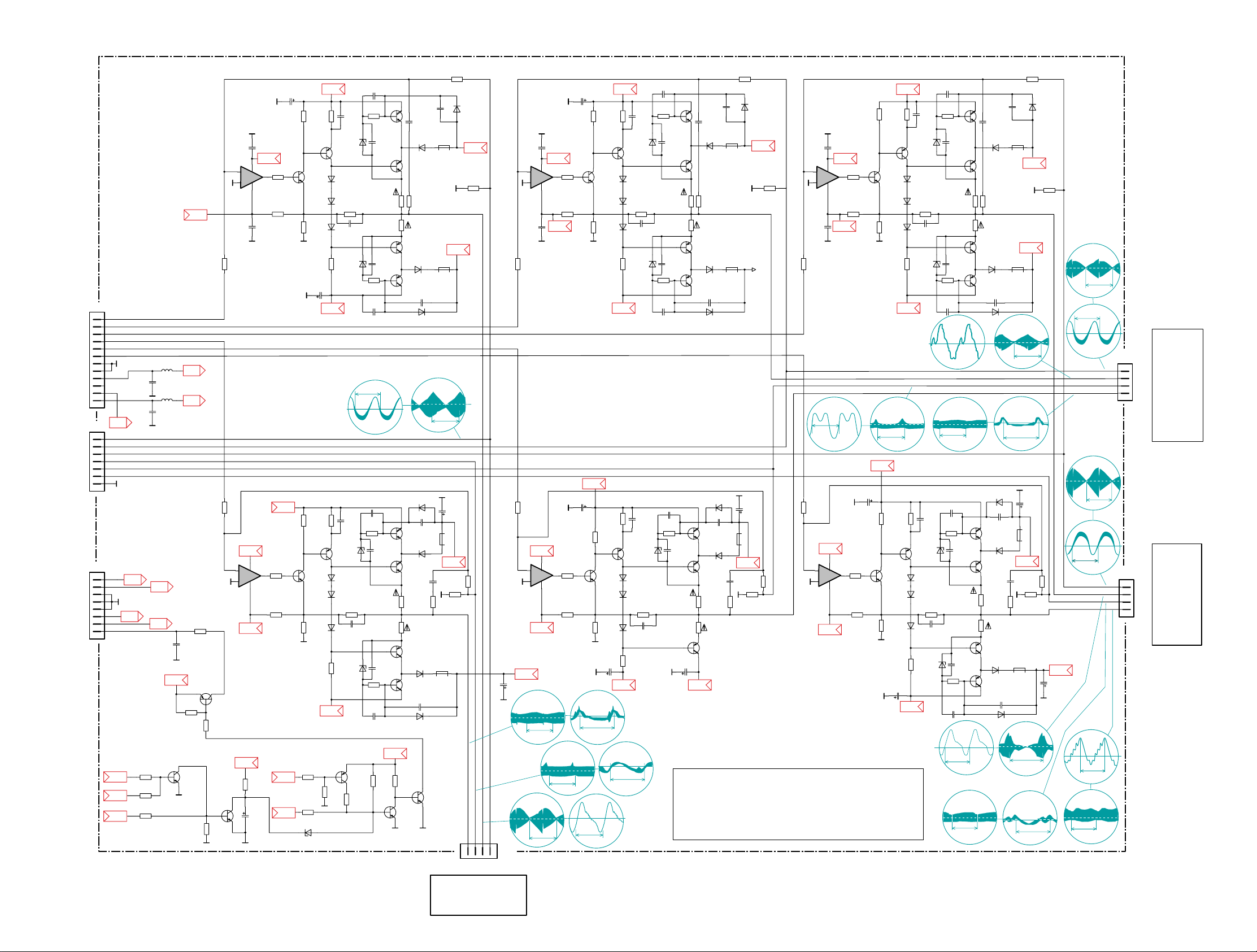
Note : The form of signals D R/G/B, RV,RH,GH,GV,BH and BV is given for information only. They may vary with the convergence settings
and the synchronisation of the oscilloscope.
Note : La forme des signaux D R/G/B, RV,RH,GH,GV,BH et BV est donnée à titre indicatif. Elle peut varier avec les réglages de convergence
et la synchronisation de l'oscilloscope.
Hinweis : Die Form der Signale D R/G/B, RV, RH, GH, BH und BV ist nur informativ. Sie können je nach Einstellung der Konvergenz und
der Synchronisation des Oszilloskops abweichen.
Nota : La forma dei segnali D R/G/B, RV, RH, GH, GV, BH e BV viene fornita solo a titolo indicativo. La forma può variare in base alle
regolazioni di convergenza e alla sincronizzazione dell’oscilloscopio.
Nota : La forma de las señales D R/G/B, RV, RH, GH, GV, BH Y BV se facilita únicamente para información. Puede diferir con los parámetros
de convergencia y la sincronización del osciloscopio.
Care must be taken to avoid short circuits when carrying out measurements around IK02 and IK03. If this happens then IK01 will be
damaged, after replacement a complete re-alignment of the set will be necessary. Therefore, when carrying out convergence drive
signal checks and measurements please use the relevant pins at PCB connector BK04.
Prendre grand soin lors de mesures sur les points de IK02 et IK03 à ne pas créer de court-circuit.Si celà arrive IK01 sera détérioré
et un alignement complet de l'appareil est nécessaire. Pour éviter celà effectuer les mesures et contrôles des signaux des drivers
aux points du connecteur BK04 de la platine CSB.
* ATTENTION!
Messungen um IK02 und IK03 müssen mit besonderer Vorsicht vorgenommen werden, da bei eventuellen Kurzschlüssen IK01
beschädigt werden kann. Nach einem Austausch von IK01 ist ein vollständiger Abgleich des Gerätes notwendig. Deshalb sollten
zum Überprüfen der Konvergenz-Treibersignale Messungen an den entsprechenden Pins des Verbinders BK04 durchgeführt werden.
Debe tener cuidado de no provocar cortocircuitos cuando se efectúen mediciones alrededor de IK02 e IK03. Si ocurren,
IK01 se dañará o destruirá. Después de la sustitución es necesario hacer un reajuste completo. Por lo tanto, cuando haya
que comprobar o medir en las señales de convergencias, utilizar siempre las patillas correspondientes del conector BK04.
Prestare molta attenzione in modo da evitare corto circuiti quando vengono effettuate misure sui circuiti integrati IK02 e IK03.
Se ciò dovesse capitare verrebbe danneggiato IK01, nel caso di sostituzione di tale componente diventa necessario effettuare un
completo allineamento. Per cui quando si devono controllare i segnali di pilotaggio di convergenza utilizzare i relativi piedini del
connettore BK04.
-13V
-13V
-13V
0,1 0,1
00000
0,1 0,1
3,3
-13V
+6V
+13A
+13A
+13A
+13B
+13V
+13V
+13V
-13B
+3.3V
+3.3V
+3.3V
+3.3V
+3.3V
3.3
3.3
-1,8
+3.3V
+3.3V
+3.3V
+3.3V
+3.3V
0,8
0,1
0,1
0,9
0,7
0
+3.3V
+3.3V
+3.3V
+13A
-13A
-13V
+13V
+3.3V
-13B
+3.3V
Page 12
RP C21
First issue 09 / 01
CONVERGENCE AMPLIFIER BOARD - PLATINE AMPLIFICATEUR DES SIGNAUX DE CONVERGENCE -KONVERGENZVERSTÄRKER-PLATINE PIASTRA AMPLIFICATORE CONVERGENZA - PLACA AMPLIFICADOR CONVERGENCIAS
+
-
+
-
+
-
+
-
+
-
+
-
BZX55C6V2
DG56 BZX55C6V2
DG09
BZX55C6V2
DG08
BZX55C6V2
DB08
BZX55C6V2
DB57
BZX55C6V2
DA57
BZX55C6V2
DB09
BZX55C6V2
DB56
BZX55C6V2
DA56
BZX55C6V2
DA09
BZX55C6V2
DA08
1N4148DA59
1N4148DB59
RGP10G
DB58
1N4148
DB60
1N4148
DA60
1N4148
DG60
1N4148
DA10
1N4148DA11 1N4148DG11
RGP10G
DB06
1N4148
DB52
1N4148
DB51
1N4148
DB50
RGP10G
DB53
1N4148
DB03
1N4148
DB02
1N4148
DB01
1N4148DB11
RGP10G
DB05
1N4148
DG52
1N4148
DG51
1N4148
DG50
RGP10G
DG53
1N4148
DG03
1N4148
DG02
1N4148
DG01
RGP10G
DA05
1N4148
DG10
1N4148
DA01
1N4148
DA02
1N4148
DA03
RGP10G
DA53
1N4148
DA50
1N4148
DA51
1N4148
DA52
RGP10G
DA06
1N4148
DB10
RGP10G
DG06
RGP10G
DG05
RGP10G
DA58
TL082CD
IA10
6
5
7
8
4
TL082CD
IB12
2
3
1
8
4
TL082CD
IG11
2
3
1
8
4
TL082CD
IA10
2
3
1
8
4
TL082CD
IB12
6
5
7
8
4
TL082CD
IG11
6
5
7
8
4
BDW93CFI
TB52
BDW93CFI
TA52
BDW93CFI
TG02
BDW93CFI
TA02
BDW93CFI
TA54
BDW93CFI
TA01
BDW93CFI
TB01
BDW93CFI
TB54
BDW93CFI
TB02
BDW93CFI
TG54
BDW93CFI
TG52
BDW93CFI
TG01
BC847C
TW02
BC847C
TW13
BC847C
TW14
BC847C
TW01
BC857C
TW10
BC857C
TW19
1K5
RW19
162R0
RA05
162R0
RA53
162R0
RG53
162R0
RB53
162R0
RB05
162R0
RG05
4K7
RA66
4K7
RB66
2K43
RG64
2K43
RB64
2K43
RA20
2K43
RA64
4K7
RG62
4K7
RG15
4K7
RG08
4K7
RB62
4K7
RA62
4K7
RB08
4K7
RB15
7K5
RB61
3K32
RB56
267K0
RB55
8K87
RB60
2K43
RB52
332R0
RB51
1K0
RB50
5K1
RB01
3K32
RB10
267K0
RB13
8K87
RB07
2K43
RB04
332R0
RB03
1K0
RB02
7K5
RG61
3K32
RG56
267K0
RG55
8K87
RG60
2K43
RG52
332R0
RG51
1K0
RG50
5K1
RG01
3K32
RG10
267K0
RG13
8K87
RG07
2K43
RG04
332R0
RG03
1K0
RG02
1K0
RA02
332R0
RA03
2K43
RA04
8K87
RA07 267K0
RA13
3K32
RA10
5K1
RA01
1K0
RA50
332R0
RA51
2K43
RA52
8K87
RA60 267K0
RA55
3K32
RA56
7K5
RA61
4K7
RA15
4K7
RA08
8K2
RW05
56K0
RW04
3K3
RW06
3K9
RW13
4K7
RW15
15K0
RW02
3K3
RW01
12K0
RW12
8K2
RW10
4K7
RW11
1K0
RW09
10K0
RW18
BZX55C8V2
DW12
BF421
TG51
BF421
TG05
BF421
TA05
BF421
TA51
BF421
TB51
BF421
TB05
1
2
3
4
5
6
7
BDW94CFI
TG53
BDW94CFI
TB03
BDW94CFI
TG03
BDW94CFI
TB53
BDW94CFI
TB55
BDW94CFI
TB04
BDW94CFI
TA55
BDW94CFI
TG04
BDW94CFI
TA04
BDW94CFI
TA03
BDW94CFI
TA53
1
2
3
4
5
6
7
8
9
10
11
12
15P0CA68
15P0CB68
100N0
CB67
15P0CA16 15P0CG16
15P0
CA61
100P0
CB60
100P0
CG60
100P0
CB10
100P0
CG10
100P0
CA60
100P0
CA10
100N0
CG56
100N0
CG08
100N0
CG07
100N0
CB56
100N0
CA56
100N0
CB07
100N0
CB08
100N0
CB03
100N0
CB02
100N0
CG03
100N0
CG02
100N0
CA02
100N0
CA03
100N0
CA08
100N0
CA07
15P0
CA15
15P0
CG15
15P0
CB15
15P0CB16
15P0
CB61
100P0
CA09
15P0
CG61
100N0
CA67
100P0
CA11
100P0
CG11
100P0CG09 100P0CB09
100P0
CB11
100P0
CG62
100P0
CA62
100P0
CB62
100P0
CB66
100P0
CA66
-
LA06
12
-
LA05
12
-
LG05
12
-
LA53
12
-
LA58
12
-
LG53
12
-
LB53
12
-
LB05
12
-
LB06
12
-
LB58
12
-
LG06
12
10K0
RA54
470MI0
RB58
470MI0
RG58
470MI0
RA58
470MI0
RB59
470MI0
RB12
470MI0
RB14
470MI0
RG59
470MI0
RG14
470MI0
RA14
470MI0
RA12
470MI0
RA59
1R8
RA57
2K43
RG20
1R8
RB09
10K0
RB06
1R8
RG09
10K0
RG06
1R8
RB57
10K0
RB54
1R8
RA09
10K0
RA06
10K0
RG54
1R8
RG57
2K43
RB20
470MI0
RG12
47U0
CB53
47U0
CB50
220U0
CG54
220U0
CG55
47U0
CG53
47U0
CG50
47U0
CG01
NI
CA01
47U0
CA04
220U0
CA55
220U0
CA54
100U0
CW05
220U0
CB54
220U0
CB55
1
2
3
4
5
6
7
8
BR01
123
4
BB01
1
2
3
4
BG01
1
2
3
4
BC546B
TB50
BC546B
TA50
BC546B
TB06
BC546B
TG06
BC546B
TG50
BC546B
TA06
47R0
RW20
100N0
CW19
10U0
LW06
100N0
CW06
100N0
CW07
10U0
LW07
1N0
CA05
22P0
CA06
1N0
CG05
22P0
CG06
1N0
CB05
22P0
CB06
22P0
CB59
1N0
CB51
1N0
CG51
22P0
CG59
1N0
CA51
22P0
CA59
+15
GVD
RHD
GHD
LFBV
LFBV
LFGH
LFGH
RVD
LFBH
LFBH
BVD
BHD
LFGV
LFGV
GV
BV
RV
GND
GND
GND
GH
+53V
BH
RH
PS_ON
LFRH
LFRH
LFRV
LFRV
+3.3V
-53V
-15
-15
-13V
+13V
M
M
S
GH
BH
RV
RH
BV
GV
SUPPLY WATCH DOG
(CAB).RP21.00
To Convergence
Deflection Coil
Blue Picture Tube
To Convergence
Deflection Coil
Red Picture Tube
To Convergence
Deflection Coil
Green Picture Tube
BK16 <=BW16
BK004 <=BW05
BP260 <=BW04
FROM CONVERGENCE
GENERATOR
FROM CONVERGENCE
GENERATOR
FROM CPS
Note : The form of signals D R/G/B, RV,RH,GH,GV,BH and BV is given for information only. They may vary with the convergence settings
and the synchronisation of the oscilloscope.
Note : La forme des signaux D R/G/B, RV,RH,GH,GV,BH et BV est donnée à titre indicatif. Elle peut varier avec les réglages de convergence
et la synchronisation de l'oscilloscope.
Hinweis : Die Form der Signale D R/G/B, RV, RH, GH, BH und BV ist nur informativ. Sie können je nach Einstellung der Konvergenz und
der Synchronisation des Oszilloskops abweichen.
Nota : La forma dei segnali D R/G/B, RV, RH, GH, GV, BH e BV viene fornita solo a titolo indicativo. La forma può variare in base alle
regolazioni di convergenza e alla sincronizzazione dell’oscilloscopio.
Nota : La forma de las señales D R/G/B, RV, RH, GH, GV, BH Y BV se facilita únicamente para información. Puede diferir con los parámetros
de convergencia y la sincronización del osciloscopio.
BHD
BHD
0
( 4- BB01 )
( 4- BB01 )
44Vpp-V
40Vpp-H
0
10m
s
32
µs
BHR
( 3- BB01 )
1Vpp-V
0
10m
s
0
BHR
( 3- BB01 )
1Vpp-V
32
µs
BVD
BVD
( 2- BB01 )
( 2- BB01 )
80Vpp-H
80Vpp-V
0
00
10
µs
32
µs
GHD
GHD
( 4- BG01 )
( 4- BG01 )
42Vpp-V
42Vpp-H
10m
s
0
0
32
µs
32
µs
32
µs
GHR
GHR
( 3- BG01 )
( 3- BG01 )
0,8Vpp-V
0,8Vpp-H
( 1- BB01 )
0
2Vpp-H
0
10m
s
GVD
GVD
( 2- BG01 )
( 2- BG01 )
35Vpp-V
30Vpp-H
0
10m
s
0
32
µs
RHD
RHR
RVR
RVR
RHR
RHD
0
0
( 4- BR01 )
( 3- BR01 )
( 1- BR01 )
( 1- BR01 )
( 3- BR01 )
( 4- BR01 )
60Vpp-V
1Vpp-V
55Vpp-V
54Vpp-H
60Vpp-H
0
10m
s
32
µs
0
10m
s
1Vpp-H
32
µs
0
10m
s
0
32
µs
2Vpp-V
BVR
( 1- BB01 )
0
10m
s
GVR
GVR
( 1- BG01 )
( 1- BG01 )
1.2Vpp-H
1.2Vpp-H
0
10m
s
32
µs
( 1- BR01 )
0
1,7Vpp-H
RVR
RVR
( 1- BR01 )
2.2Vpp-V
0
10m
s
0
32
µs
-0,15
0
53,3
-0.5
51,8
-0.2
-1.1
-53
-15
-14.7
53,3
52,4
16
16.1
-0.5
0
-0.7
-0.8
-1,2
-15,3
-15.1
0
-1
-1,1
0
-0.5
-0.5
51,8
52,4
0,9
0
14,8
14,9
0
-0.5
-1
51,8
52,4
14,4
14,6
0
-1
-14,4
-14,6
-53
15.4
0,9
0
53,3
-0.4
-13
-0.4
-13
13
0
51,8
0.7
-0.1
0,2
-1.3
-1.2
-14,9
15
15,1
53,3
52,4
-0.5
-13
51,8
0.6
0.6
-0,3
52,4
53,3
15,1
15
-0.4
-0.5
-1.5
-14,4
-15
-53
-0.4
-1,2
51,8
52,4
-0.3
0,9
15.3
53,3
15
0
0
-1
-15
-15.2
+15
+15
+15
+15
+15
+15
-13A
-13
+13
-13A
-13A
-13A
+13A
+13A
0,6
0,6
0
0
0
4,8
-0,8
0,7
-0,7
+13A
+13A
+13A
+13A
+13A
13
+53V
+53V
+53V
+53V
+53V
+53V
+3.3V
13
12,3
+3.3V
+3.3V
-53V
-53V
-53V
-53V
-53V
-53
-53V
-53V
-53
-15
-15
-15
-15
-15
-15
-15
+15
+15
-13A
-13A
+13A
+13A
+13A
13
0
+53V
-13A
-13A
Page 13
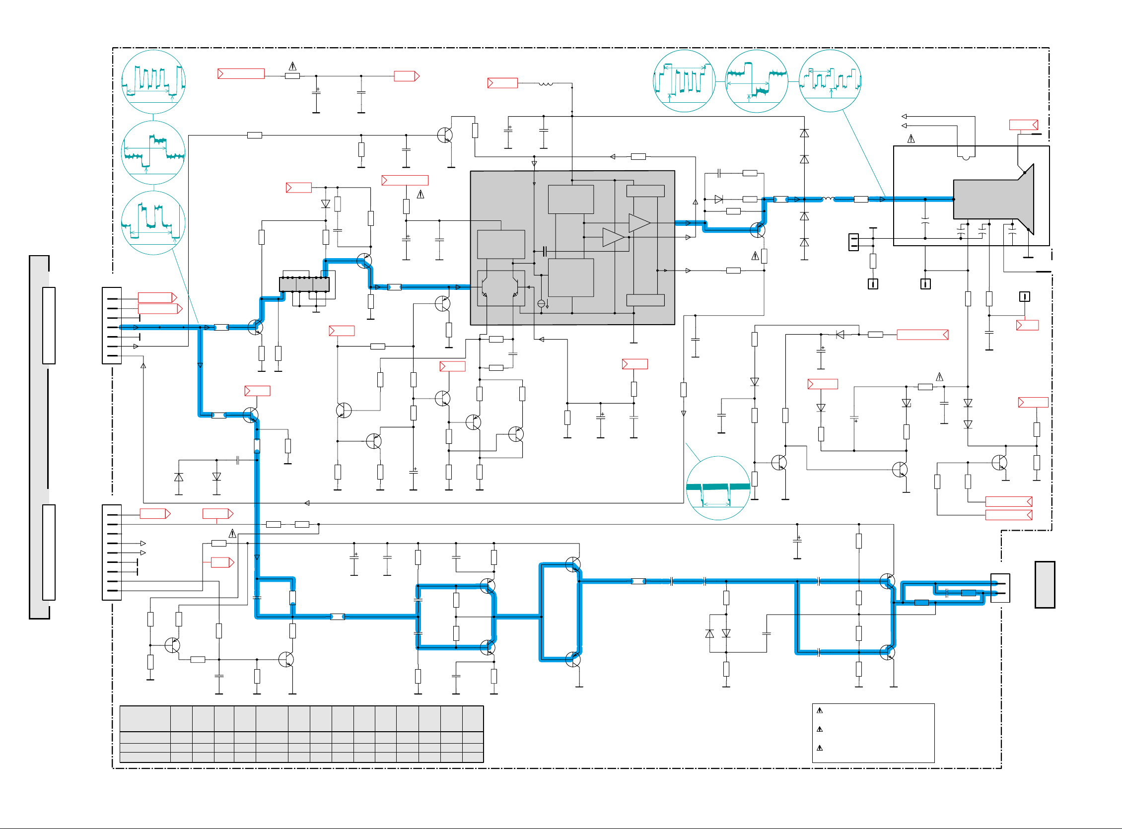
out 4x
0.7pF
5mAJ
+
in
CURRENT
INPUT
1x
out 1x
MIRR0R
1x
in out
VIN-
RC- RC+
VCC
VIN+
IIN VDD
MIRROR
4x
in out
GND
CASCODE
OUTM
OUT
OUTC
1x
CASCODE
n.c.
n.c.
G1 G2 G3
AQU
CATHODE
HEATER
ANODE
1
2
1
2
3
4
5
6
7
8
9
2SD1684
TG*07
BZX85C100
DB*66
1N4148
DG*02
1N4148
DG*01
1N4007GP
DB*68
1N4007GP
DB*67
1N4148
DB*60
1N4148
DB*62
100N0
CG*14
BC856B
TG*34
10K0
RG*31
100R0
RG*03
BC846B
TB*35
BC846B
TB*61
BC846B
TB*01
BC846B
TB*55
BC846B
TB*33
BC337-40
TG*02
BC846B
TG*11
BC546B
TG*01
BC846B
TG*35
1N4148
DG*36
BB*58
1
BB*70
100U0
CG*01
22U0
CG*10
47U0
CB*21
4U7
CB*23
47U0
CB*41
47U0
CB*25
4U7
CB*66
47U0
CB*39
47U0
CB*62
10U0
LB*52
68U0
LB*23
10N0
CG*08
TH288LNMS-14729
FB*01
123456789
10
11
12
131415
161718
BB*51
1
2
BAV21
DB*52
BAV21
DB*54
1N4148
DB*06
BAV21
DB*53
BAV21
DB*51
0
RB*43
0
RB*40
BC856B
TB*37
BC856B
TB*31
BC856B
TB*11
BC327-40
TG*04
BC556B
TG*05
BC856B
TB*32
100R0
RB*57
3K3
RG*27
10K0
RB*55
10K0
RB*56
10R0
RB*58
1K5
RB*71
39K0
RB*50
330R0
RB*54
3K3
RG*26
22R0
RG*30
1K0
RG*06
82K0
RG*32
1K0
RG*19
8K2
RG*07
82K0
RG*21
1K0
RG*29
390R0
RG*42
330R0
RB*53
10R0
RB*22
10R0
RB*25
0
RB*46
47R0
RG*12
56R0
RG*14
1K0
RG*23
12K0
RG*39
100N0
CG*03
100R0
RG*08
3R3
RG*13
1K82
RB*33
330R0
RB*34
10K0
RB*35
2K2
RB*38
100R0
RB*32
909R0
RB*31
33R0
RB*21
4K7
RB*51
825R0
RB*41
3M3
RB*66
2K2
RB*67
100K0
RB*62
100K0
RB*60
100K0
RB*61
22K0
RB*63
1K5
RB*69
100K0
RB*64
681R0
RB*07
33R0
RB*01
475R0
RB*06
475R0
RB*08
1K0
RB*11
300R0
RB*10
180K0
RG*04
47R0
RG*01
1K0
RG*05
8K2
RG*09
180K0
RG*40
10K0
RB*14
47R0
RG*41
560K0
RB*81
150K0
RB*82
100R0
RB*80
2K0
RB*39
2K94
RB*37
100R0
RB*36
1K3
RB*30
392R0
RB*42
1K0
RG*38
1K0
RG*35
2K21
RB*27
332R0
RB*26
100K0
RB*83
7K15
RB*28
BF422
TB*80
BF420
TB*66
1K5
RB*65
TDA6120Q
IB*01
1
2
34
5
6
7
8
9
10
11
12
13
100R0
RB*23
JB*95
10N0
CG*06
22N0
CG*07
22N0
CG*09
100N0
CG*05
47P0
CG*48
10N0
CB*24
100N0
CB*42
22P0
CB*34
47P0
CB*09
22N0
CB*22
100N0
CG*37
22N0
CB*26
1N0
CB*71
100N0
CG*04
1U0
CG*31
22N0
CG*02
1N0
CB*61
470P0
CB*67
47P0
CG*54
22N0
CG*12
22N0
CB*56
1
2
3
4
5
6
7
BC856B
TB*12
2SB1144
TG*06
470R0
RB*45
BB*10
15
67
8
910
12
330R0
RG*37
680R0
RB*09
1N5
CB*40
1N4148
DB*40
BF421
TB*40
470R0
RB*44
150P0
CB*44
1N4148
DG*37
BAV21
DB*64
4K7
RG*34
100K0
RG*28
100K0
RG*36
JB*90
BB*59
1
GNDA
GNDA
HEATER_LOW
GNDC
G2ADJUST
V-GND
V-GND V-GND
V-GND V-GND
V-GND
V-GND
V-GND V-GND
V-GND
V-GND
V-GND V-GNDV-GND
V-GND V-GNDV-GND
V-GND
V-GND V-GND
V-GND
V-GND
V-GND
V-GNDV-GND
V-GND
V-GNDV-GNDV-GND
V-GND V-GND
V-GNDV-GND
V-GNDV-GND
V-GND
V-GND
V-GND
V-GND
V-GND
V-GNDV-GND
V-GND
V-GNDV-GND
V-GND
V-GNDV-GND
V-GNDV-GNDV-GND
V-GND
V-GND
V-GND
#
#
#
#
#
#
#
#
#
#
#
#
#
#
#
##
#
#
#
##
#
#
#
#
M
M
M
Reference Volt.
SPOT KILLER
BSVM-ATTENUATOR
BSVM-DRIVER
BSVM-OUTPUT STAGE
BSVM
aux-coil
to
FOK
VIDEO DELAY
to EHT
splitter
S.L.B
Input
DCR
DCR
HEATER_HIGH
HEATER_LOW
BSVM-Blank
DCR
BG*03=>
BSVM
BV01,02,03<=BB*03
BV06,07,08<=BB*01
ADB
Safety Part
When repairing, use original part only
Piece de securite
N'utilisez que les pieces d'origine
Bei Ersatz nur Originalteil verwenden
Sicherheitsbauteil
CRT B RP21 00 : * = 3
CRT G RP21 00 : * = 2
CRT R RP21 00 : * = 1
+12VSUPPLY
+12VSUPPLY
+12VSUPPLY
+12VSUPPLY
HEATER_HIGH
HEATER_LOW
UVIDEO
UVIDEO
UVIDEO
G2ADJUST
G2ADJUST
+12V
+12V
11,7
3,5
2,9
3,1
0
0,6
0,1
0,1
0,7
0
235
3,9
3
3,8
5,5
5,5
+12V
11,7
+12V
10,8
10
0,9
0
0
2,2
2,1
2,9
6
2,2
1,6
0,1
0,5
0,2
20
1,2
0,5
20,9
10,6
10,6
10,7
21,4
10,6
10,7
42,6
25,6
25,6
43
0,3
1,7
1,9
4,2
1,6
11,5
242
212
227
235
10,2
2,6
2,6
2
1,6
+12V
+12V
1KV
+30 KV
UVIDEO
+12Vsupply
USYS
USYS
+20V
+20V
UVIDEO
HEATER_HIGH
HEATER_HIGH
HEATER_LOW
130Vpp-H
0
100V
32us
130Vpp-H
57V0
32us
30Vpp-H
200V
0
32us
CRT-B
CRT-R
CRT-G
DCR
2.5Vpp-H
2V1
0
0
32us
VIDEO G
VIDEO B
VIDEO R
2Vpp-H
0
2,5V
32us
1,5Vpp-H
7Vpp-V
1,5V
0
32us
10ms
39P027P0
33P0
47P0
CB*09
3K322P0
12P0
1K21
RB*37
RB*38
RB*35
1K82
7K15
8K66
-
RB*28
681R0
681R0
562R0
RB*07CB*34
X
RB*14
2K21
1K82
TB*12
TB*31-33
RB*26+30
RB*31+39
RG*23
RB*27
+37
TB*35RB*33
X
-
RB*32
CRT G RP21 00
CRT B RP21 00
CRT R RP21 00
XXX
---
TB*31
--
CB*39
RB*58
BB*58
-
-- ---
#
X
X
XX
XX
X
-
VIDEO AMPLIFIER BOARD - PLATINE AMPLIFICATEURS VIDEO - VIDEOVERSTÄRKERPLATTE - PIASTRA AMPLIFICATORE VIDEO - PLATINA AMPLIFICADOR VIDEO
First issue 09 / 01
RP C21
Page 14

RP C21
First issue 09 / 01
ADAPTER BOARD - PLATINE ADAPTATEUR - ADAPTER-PLATINE - PIASTRA ADATTATORE - PLACA ADAPTADOR
P
10K0
RV91
33K0
RV58
JV30
1M0
RV48
10K0
RV21
10K0
RV92
BC846B
TV22
1K2
RV49
1K0
RV47
100R0
RV67
12K0
RV10
4R7
RV09
100K0
RV19
33K0
RV18
10K0
RV24
1M0
RV37
22K0
RV71
150K0
RV2018K0
RV36
22K0
RV27
100R0
RV38
681R0
RV22
681R0
RV26
681R0
RV17
2K21
RV32
750R0
RV34
22K0
RV35
2K21
RV30
1K0
RV39
47K0
RV41
5K36
RV31
2K21
RV33
18K0
RV81
100R0
RV65
1M0
RV53
1K5
RV51
2K2
RV50
47K0
RV59
1M0
RV52
47K0
RV56
150K0
RV55
2K2
RV57
330K0
RV11
100R0
RV13
2K2
RV12
4R7
RV01
330K0
RV03
2K7
RV02
330K0
RV04
2K2
RV07
3K3
RV06
22K0
RV08
3K65
RV25
1K0
RV42
1M0
RV54
2K7
RV23
39K0
RV80
1K0
RV85
18K0
RV87
3K3
RV82
4K7
RV70
270K0
RV84
270K0
RV83
100K0
RV73
100K0
RV72
8K66
RV45
47R0
RV05
750K0
RV14
100R0
RV15
LV80
1
2
3
4
5
6
BF421
TV01
BV23
2SC3675
TV80
1
2
3
4
5
6
7
8
9
1
2
3
4
5
6
7
8
9
1
2
3
4
5
6
7
8
9
1
2
3
4
5
6
7
8
9
10
1
2
3
4
5
6
7
8
9
1
2
3
4
5
6
7
8
9
220U0
LV01
10K0
RV28
4K7
RV74
-
IV10
1
2
3
BV20
1
2
3
4
5
6
7
1
2
3
4
5
6
7
1
2
3
4
5
6
7
1
2
3
4
5
6
7
400MI0
ZV90
BC856B
TV35
BC856B
TV03
BC856B
TV32
BC856B
TV30
BC856B
TV02
BC856B
TV20
BC846B
TV34
BC846B
TV31
BC846B
TV50
BC846B
TV33
BC846B
TV53
BC846B
TV51
BC846B
TV04
BC846B
TV52
3K65
RV29
1N4148
DV24
1N4148
DV23
1N4148
DV25
1N4148
DV30
1N4148
DV20
1N4148
DV22
1N4148
DV21
1N4148
DV80
1N4148
DV50
RGP10G
DV03
RGP10G
DV02
RGP10G
DV01
1N4148
DV52
BYD43-20
DV86
BYD43-20
DV85
1N4148
DV53
RGP10G
DV90
4U7
CV32
100U0
CV55
100U0
CV10
10U0
CV02
10U0
CV03
4U7
CV33
470U0
CV90
1
2
1
2
BZX55C3V3
DV70
BC846B
TV21
10U0
LV90
100N0
CV12
100N0
CV30
100N0
CV11
470U0
CV09
1N0
CV72
330N0
CV50
22N0
CV54
4N7
CV86
910P0
CV81
1N0
CV80
10N0
CV71
22N0
CV53
BV24
10N0
CV70
4N7
CV85
22N0
CV57
330N0
CV52
100N0
CV31
100N0
CV56
100N0
CV20
330P0
CV91
4U7
CV01
100R0
RV16
BC846B
TV40
1K0
RV40
1K0
RV44
GND_VGND_V
GND_V
GND_V GND_V
GND_V
GND_V GND_V
GND_V
GND_V
GND_V
GND_V
GND_V GND_V
GND_V
GND_VGND_V GND_V
GND_V
G2_ADJUST
ICUT
GND_L
GND_L
GND_L
GND_L
GND_L
GND_L
GND_L GND_L GND_L
GND_LGND_LGND_LGND_L
GND_LGND_L
GND_LGND_L
GND_LGND_LGND_L
GND_L
GND_L
GND_LGND_L
GND_LGND_LGND_L
GND_L
GND_L
GND_L
GND_L
GND_L GND_L
GND_L
GND_L
GND_L
GND_CRT
GND_CRT
from PS21
MC7812CT
Green CRT
Blue
Green
Red
to CRT BB303 G
S.L.B.
S.L.B
FOC.GEN.
DYN.
Peak current
VV
V
V
V
V
H
H
H
H
H
H
Blue peak
OUT
IN
ADB.RP21.00
from ICC21 BV300
BB201 BB301 BB101
U-Video
to red CRT boardto green CRT boardto blue CRT board
BV05=>BB300
BV04=>BB303
CRT G
CRT B
SSBCRT R
CRT G
CRT B
BV07=>BB301
BV08=>BB201
BV06=>BB101
GND_V
GND_V
GND_V
GND_V
GND_V
GND_V
ABL1
G2_ADJUST
G2_ADJUST
G2_ADJUST
G2_ADJUST
BLK_CUR.
S.L.B.
S.L.B.
S.L.B.
DCR-blue
DCR-red
DCR-green
GREEN-out
RED-out
Blue-out
V-GND
V-GND
V-GND
BSVM_BLANK
BSVM_BLANK
GNDV
B_IN
G_IN
R_IN
Heater low
Heater high
NC
Usys
BV01
BL200
PSB
BV03=>BB203BV02=>BB103
HDEFL1
DYF
HDEFL2
VPR1
VSAW
from ICC21
D.FOCUS<=BV18
PSB
CSB
PSB
BK02<=BV12
BL500<=BV11
BL035<=BV14
BV13
UCSB
+Uvert
BF001
from ICC21 BL500
Vsync
H-Flyb
V-para
RPsafety
GND_L
-Uvert
to CSB BK02,BK09
from ICC21
BV22
BV21
BV16BV15 BV17
BLUE REDGREEN
H-LOW
NC
Usys
U-Video
Vpara Vertical parabola
Vsync. Vertical syncronisation
H-Flyb. Horizontal flyback signal
BSVM_BLANK Beam scan velocity modulation Blanking
Usys System voltage
N.C. Not connected
DFY Dynamic focus modulation
U-video Video supply voltage
GND_V Video ground
GND_L Ground line deflection
HDEFL Horizontal line deflection
Abbreviations:
DCR-red Dark curr ent red amplifier
BLKCURU Black current
R_in Red signal input
ICUT current cut off
S.L.B. Scan loss Blanking
1
2
3
4
1
2
3
4
1
2
3
4
V
H
V
H
V
H
U-Video
BSVM_BLANK
Heater
Heater
NC
Usys
U-Video
CRT R
BSVM_BLANK
Heater
Heater
NC
Usys
2Vpp-H
0
2.5V
32us
32us
2.2Vpp-H
2V
0
32us
1Vpp-H
2V
0
32us
500 Vpp-V
300v
0
10ms
0
3.5Vpp-V
4Vpp-H
32us
6Vpp-H
1200 Vpp-V
0
10ms
+12V
+15V
-13V
+13V
+6V
+12V
+12V
+12V
+20V+20V+20V
+12V
6
6,5
5,9
10,8
+12V
+12V
+12V
+12V
485
242,3
242
2,2
3,5
4
+12V
+12V
+20V
3,7
00
0,8
2,9
5
5
5,1
4,5
6,4
6,9
8,6
10,2
5,4
5,4
5,8
7,9
5,3
4,6 4,6
2,9
00
0,7
0,7
-1,5
-9
0,7
0
0
-3,2
Page 15

RP C21
First issue 09 / 01
CONVERGENCE POWER SUPPLY - ALIMENTATION DES CIRCUITS DE CONVERGENCE - APAPTER KONVERGENZ-NETZTEILPLATINE - ALIMENTAZIONE CONVERGENZA ALIMENTACIÓN CONVERGENCIAS
LP50
3
4
5
7
8
9
11
12
13
16
17
BP60=>
BW04
CAB
1
2
3
4
5
6
7
8
BC856B
TP27
BC856B
TP20
BC856B
TP28
BC556B
TP45
BC556B
TP24
BC337-40
TP33
BC846B
TP21
BC846B
TP91
BC846B
TP90
<= BP10
BP010
(PS).RP21
1
2
-
TP30
1N4148
DP40
RGP15G
DP65
S410D
DP75
RGP15G
DP60
S410D
DP70
1N4148
DP30
BAV21
DP20
1N4148
DP41
1N4148
DP49
1N4148
DP44
1N4148
DP48
1N4148
DP45
1N4148
DP46
1N4148
DP47
47U0
CP12
22U0
CP61
220U0
CP60
220U0
CP65
22U0
CP66
220U0
CP76
1MI0
CP75
220U0
CP71
1MI0
CP70
22K0
RP50
825R0
RP92
1K58
RP93
470R0
RP91
1K5
0W25
RP87
22R0
RP88
220R0
RP43
10K0
RP45
3K3
0W25
RP46
15K0
RP37
1K5
RP34
100R0
RP49
5K6
RP44
47K0
RP33
22K0
RP48
100R0
RP39
470R0
RP28
2K2
0W25
RP41
22K0
RP42
10K0
RP47
10R0
RP31
2K2
RP40
1N0
CP50
1k6V
3N3
CP30
0W25
220K0
RP12
22R0
RP22
220R0
RP23
4K7
RP21
10K0
RP20
10K0
RP24
33R0
RP30
4R7
3W
RP32
0W25
220K0
RP10
470R0
RP26
22K0
RP25
1K5
RP27
0W25
220K0
RP11
0W25
220K0
RP13
BZX55B15
DP24
BZX55B10
DP38
BZX55B15
DP23
BZX85C16
1.3W
DP31
DP37
BZX
55A5V1
DP87
BZX85C16
1.3W
DP32
100R0
RP29
68U0
LP65
68U0
LP70
68U0
LP75
68U0
LP60
1N0
CP28
22N0
CP90
22N0
CP86
100N0
CP22
470P0
CP40
1N0
CP29
470P0
CP39
10N0
CP37
1N5
CP33
1N0
CP31
1U0
CP21
47U0
CP23
470U0
CP46
10U0
CP49
10U0
CP42
1U0
CP87
1U0
CP91
1U0
CP20
TCET1103G
IP50
1
2
3
4
SGND
SGND SGND SGND SGND SGND SGND
SGND
SGND
SGND
SGND
SGND
SGND
SGND
SGND SGND
SGND
ON/OFF
PGND
PGND
PGND
PGND
PGNDPGNDPGNDPGND
PGND
PGNDPGND PGND PGND PGND PGND
PGND
PGND PGND PGND PGND PGNDPGND PGND
PP 21400
50V
STP3NB90FP
13/14/15
1/2
(PS).RP21.00
E
C
K
A
+331V (289)
(15)
(14,9)
(0)
(0)
(0)
(0)
(0)
12,6 12,6
11,9
369
0,4
3,4
(0)
3,4
(0)
0,4
11,7
11,6
12
4,8
(0)
(0)
(287)
5,1
12,3
11,2
(0)
(1,9)
(-0,1)
4,5
(0)
15,4
0
15,1
15,1
0,6
1,2
5.1
1,3
0
: DC Voltages -TV ON
(0)
: DC Voltages -TV STBY
(14,9)
(14,9)
(14,9)
(0)
0
(0)
(0)
(0)
(0)
(0)
-15V
+53,6V
+15V
-53V
(0)
(0)
(0)
+12,3V
(0)
(43)
T= 25
µs
T= 25
µs
14Vpp-H
1,2Vpp-H
0
0
0
0
T= 25
µs
790 Vpp-H
T= 25
µs
2Vpp-H
Part of board connected to mains supply.
Partie du châssis reliée au secteur.
Primärseite des Netzteils.
Parte dello châssis collegata alla rete.
Parte del chassis conectar a la red.
Note :
During measurements in the power supply unit
- Use the primary power unit ground (PGND).
Attention :
Mesure dans la partie primaire de l'alimentation
- Utiliser la masse du bloc alimentation (PGND).
Achtung :
Bei Messungen im Primärnetzteil
- Primärnetzteilmasse verwenden (PGND).
Attenzione :
misure nell'alimentatore primario
- usare massa alimentazione primario (PGND).
Cuidado :
Medida en el bloque de alimentacion
- Utilizar la masa del bloque de alimentacion
(PGND).
Use isolating mains transformer.
Utiliser un transformateur isolateur du secteur.
Einen Trenntrafo verwenden.
Utilizar un transformador aislador de red.
Utilizzare un transformatore per isolarvi dalla rete.
!
Page 16

RP C21
First issue 09 / 01
POWER / SCAN BOARD - PLATINE ALIMENTATION / BALAYAGE - NETZTEIL- UND ABLENKPLATINE - PIASTRA DEFLESSIONE / ALIMENTAZIONE - PLACA ALIMENTACIÓN / BARRIDOS
POWER SUPPLY PART - PARTIE ALIMENTATION - NETZTEIL - ALIMENTAZIONE - ALIMENTACIÓN
230V
~
U_MAINS
v
1M5
RP401
470N0
CP401
JP941
JP940
JP942
3.15
T3.15AL
FP401
BP401
DEV
LP402
DEV
LP401
ERZV14D511
RP402
1
3
3
1
1
1
1
4
4
2
2
2
3
2
2
BP402
*
*
*
*
switch
Mains-
!
!
!
!
!
!
!
15MI015MI0
12M0 -
-
X
*
LP402LP401
JP941
JP940
MIS 21001 00
MIS 21000 00
+
-
+
-
+
-
+
-
+
-
+
-
P
T
LP020
1
2
3
4
5
6
7
8
10M0
RP050
T2.5AL
FP001
LP050
1
2
4
5
6
7
8
9
10
12
13
14
15
16
17
18
19
20
21
22
TCET1103G
IP070
1
2
3
4
TCET1103G
IP030
1
2
3
4
RGP15G
DP061
RGP10M
DP021
RGP15G
DP220
1N4148
DP230
1N4148
DP160
1N4148
DP161
1N4148
DP178
RGP15G
DP240
RGP15G
DP241
470R0
PP180
TL431ACLP
IP240
BP150=>BP501
SIGNAL BOARD
1
2
3
4
5
L78M05ABV
IP250
1
2
3
-
LP008
4
3
-
LP008
1
6
IP020
LM393N
IP170
6
5
7
8
4
LM393N
IP190
2
3
1
8
4
LM393N
IP190
6
5
7
8
4
LM393N
IP170
2
3
1
8
4
LM393N
IP050
2
3
1
8
4
LM393N
IP050
6
5
7
8
4
CFU110X-8MH
LP070
1
23
4
47U0
CP190
47U0
CP250
BP110
BP005
1
2
3
4
5
6
7
8
9
10
11
12
13
14
15
16
17
18
19
20
21
BC556B
TP210
BC327-40
TP051
BC556B
TP179
CP179
330P0
BC556B
TP081
BC556B
TP180
3.15
ZP009
BP121
1
2
3
TP020
560N0
LP051
BP120=>BP001
TAK
1
2
3
BZX55B15
DP053
BZX85C10
DP022
470P0
CP009
100N0
100P0
CP204
1N0
CP030
22N0
CP028
1N0
CP053
470P0
CP008
470P0
CP051
100N0
CP063
1N0
CP073
100P0
100N0
CP071
2N2
CP027
22N0
CP026
220N0
CP024
1N0
CP021
470P0
470P0
CP141
CP151
470P0
CP056
100R0
RP171
4K7
RP078
470K0
RP019
47K0
RP030
3K3
RP201
2K2
RP170
82K0
RP029
1K0
RP211
10K0
RP212
1K0
RP210
RP213
10K0
RP202
4K7
RP204
3K3
100K0
RP203
RP220
CP175
4K7
RP070
1K0
RP073
10K0
RP080
100R0
1K0
RP032
RP033
1K0
RP160
39K0
RP183
47K0
10N0
RP026
CP031
4K75
RP184
10K0
RP067
15K0
RP199
1K0
RP189
100K0
RP191
47K0
RP190
470R0
1K0
RP193
1K0
RP194
1K2
RP195
10K0
RP075
22K0
RP196
12K0
RP222
1K0
RP152
68K0
RP027
33R0
RP053
100R0
4.5W
RP051
100K0
RP068
100K0
RP063
RP054
100R0
4K7
RP055
RP056
1K0
RP151
1M0
RP007
10K0
RP069
3K3
RP072
2K2
1K0
RP071
RP035
TP034
CP034
RP034
4K7
BC556B
100R0
RP153
4K7
RP024
100R0
RP020
10R0
RP023
10K0
RP021
22K0
RP223
100R0
RP224
4K7
RP178
1K0
RP230
39K0
RP231
56K0
RP185
1K5
RP182
CP180
100N0
220R0
RP161
100R0
RP137
10K0
RP130
10K0
RP135
10K0
RP112
0W43
4K7
RP113
392R0
RP242
RP028
47R0
22K0
RP197
10K0
RP198
2K2
RP164
10K0
100P0
RP162
CP162
82K0
RP163
100K0
RP166
4K7
RP181
1K0
RP243
1K5
RP240
4K7
RP172
22K0
RP173
10K0
RP175
22K0
RP174
10R0
RP176
1K0
RP165
820R0
RP180
RP900
12K0
RP179
4K7
RP076
0W43
4K7
RP114
180K0
RP025
100R0
RP192
2K2
RP077
1K5
RP062
RP031
150R0
33R0
RP049
47R0
RP239
10K0
RP074
10K0
RP241
47R0
RP150
100R0
RP221
100R0
RP065
1K0
RP188
10K0
RP186
10K0
RP187
82K0
RP177
47K0
RP200
47R0
RP022
CP011
1N5
0W43
4K7
0W43
4K7
RP117
RP120
10K0
RP066
100MI0
2.5W
RP052
10R0
RP061
5K6
RP064
100N0
CP197
10N0
CP221
220P0
CP019
220P0
CP022
150P0
CP050
4N7
CP005
4N7
CP004
4N7
CP003
1U0
400V
CP006
560N0
250V0
CP007
2N2
CP052
470P0
CP131
470P0CP136
1N0
CP137
470P0
CP121
470P0
CP111
1N5
CP112
10N0
CP171
100N0
CP182
100N0
CP196
10N0
CP195
1N5
CP049
100N0
CP172
10N0
CP241
220N0
CP230
10N0
CP152
47U0
16V
CP199
390U0
450V
CP010
100U0
25V
CP023
220U0
25.0V
CP220
2MI2
CP150
4MI7
CP140
220U0
35.0V
CP135
220U0
35.0V
CP130
330U0
CP120
220U0
CP110
220U0
25V
CP062
100U0
CP170
1MI0
16V
CP240
BP001
1N4148
DP029
FUF5404
DP007
MUR160
DP020
1N4148
DP170
1N4148
DP193
GP30M
DP003
GP30M
DP001
GP30M
DP002
GP30M
DP004
MUR160
DP051
GP30M
DP006
FUF5404
DP008
1N4148
DP080
1N4148
DP060
BAV21
DP023
DP150
BYW29-150
DP140
MUR160
DP113
MUR1100E
DP112
LP114
22U0
1N4148
DP197
MUR420
DP130
MUR420
DP135
-
DP110
1N4148
DP200
1N4148
DP225
MUR1100E
DP111
1N4148
1N4148
DP030
DP033
S410DDP120
1N4148
DP081
1N4148
DP171
1N4148
DP221
1N4148
DP179
1N4148
DP180
BAV21
DP222
BC337-40
TP050
BC546B
TP026
BC546B
TP221
BC546B
TP160
BC546B
TP161
BC546B
TP197
BC337-40
TP170
BC327-40
TP150
BC546B
TP080
JP912
JP911
LP150
15K0
RP225
47U0
LP151
47U0
LP140
10R0
RP004
1
2
LP113
330R0
RP060
100U0
LP112
220P0
CP061
220P0
CP113
CNT2_20V
CNT2_20V
CNT2_20V
33V
33V
(HP) 33V
7V_STBY
7V_STBY
7V_STBY
(RP) 7V_STBY
PS_ON
PS_ON
AQR_ON
AQR_ON
AQR_ON
+UA
+UA
+UA
3V3_STBY
3V3_STBY
3V3_STBY
(RP) 3V3_STBY
PWM
PWM
INF_POW_FAIL
(RP) INF_POW_FAIL
INF_POW_FAIL
DEGAUSS
DEGAUSS
10V
10V
PO
PO
PO
SAFETY
SAFETY
SAFETY
ECO_STANDBY
ECO_STANDBY
ECO_STANDBY
-UA
GNDS
-UA
-UA
6V
6V
H_DRIVE
6V
GNDS
5V_STBY
5V_STBY
5V_STBY
3V3_STBY
5V_STBY
5V_STBY
(RP) 5V_STBY
5V_STBY
20V
20V
USYS
USYS
CNT1_20V
CNT1_20V
GND
GND
GND
GND
GND
GND
GND
GND
GND
GND
PGND
PGND
PGND
PGNDPGND
PGND
PGND
PGND
PGND
PGND
PGND
PGND
PGND
PGND
PGND
PGND
PGND
PGND
PGND
PGND
PGND
PGND
PGND
PGND
PGND
PGND
PGND
PGND
PGND
PGND
PGND
SPW17N80C2
VIPER20
16.0V
BYT08PI-1000
#
0W25
0W43
BYW29-150
#
#
16.0V
21
2W0
0W25
200.0V
35.0V
2KV
0W25
A
K
C
E
A
K
C
E
OUT
IN
GND
VCC-
ININ+
OUT
VCC+
VCC-
IN-
IN+
OUT
VCC+
VCC-
IN-
IN+
OUT
VCC+
VCC-
IN-
IN+
OUT
VCC+
VCC-
IN-
IN+
OUT
VCC+
VCC-
ININ+
OUT
VCC+
2
1
4
3
5
VDD
COMP
DRAIN
S
OSC
-
+
13V
BP500
1
21
BA010
1
6
SIGNAL BOARD
AUDIO PART
AP.21010
SIGNAL POWER PART
SPP.21000
!
!
!
!
!
!
!
!
!
BP130
6
5
4
3
2
1
GNDS
MIS.21000
MIS.21001
MAINS
FILTER
MIS
# = see partlist DP 21...00
220U0
CP114
35.0V
PP 21400 00
(PP) POWER SUPPLY
PSB
Safety Part
When repairing, use original part only
Piece de securite
N'utilisez que les pieces d'origine
Bei Ersatz nur Originalteil verwenden
Sicherheitsbauteil
!
Part of board connected to mains supply.
Partie du châssis reliée au secteur.
Primärseite des Netzteils.
Parte dello châssis collegata alla rete.
Parte del chassis conectar a la red.
Use isolating mains transformer.
Utiliser un transformateur isolateur du secteur.
Einen Trenntrafo verwenden.
Utilizar un transformador aislador de red.
Utilizzare un transformatore per isolarvi dalla rete.
!
Note :
During measurements in the power supply unit
- Use the primary power unit ground (PGND).
Attention :
Mesure dans la partie primaire de l'alimentation
- Utiliser la masse du bloc alimentation (PGND).
Achtung :
Bei Messungen im Primärnetzteil
- Primärnetzteilmasse verwenden (PGND).
PGND
Attenzione :
misure nell'alimentatore primario
- usare massa alimentazione primario (PGND).
Cuidado :
Medida en el bloque de alimentacion
- Utilizar la masa del bloque de alimentacion
(PGND).
PGND
RP010
1K0
PGND
!!
PGND
!
!
!
12
10N0
CP201
PGND
BP010
To PS RP21
(BP210)
2
1
PGND
RP 4:3 or RP 16:9 Rear Projector JP912 33K2 137V
Tube name Description Usys RP900 Usys
jumper Usys divid.
6Vpp-H
400Vpp-H
3Vpp-H
3V
-0.1V
0
0
0
T=32µs
0
0.1
0
12.4Vpp-H
T=32µs
500Vpp-H
T=32µs
T=32
µ
s (ON)
T=50
µ
s (STBY)
0
12Vpp-H
T=32µs
2Vpp-H
2Vpp-H
0.6V
0
0
T=32µs
T=32
µ
s
T=32µs (ON)
T=50
µ
s (STBY)
0.3
9.2
12
0
2.2
12
12
0.3
1.7
7.2
1.9
2
2
2.2
2.3
(10.7)
0.3
(0.3)
1.4
4.5
(4.5)
11
(11)
1.4
(1.6)
(1.6)
(315)
319
(1.6)
6.8
0.1
8.5 : DC VOL
T
AGE TV ON
(9.2) : DC VOL
T
AGE TV Standby
0.2
45.3
6.5
5.2
5
1.6
0.8
0.2
6.5
5.2
2.9
5.7
2.5
(2.5)
2.3
1.6
(1.7)
3.7
3.6
(0.6)
(0)
0
-UA
-15.8
21.4
20
3V3_STBY
4.4
(4.5)
4.9
(4)
4.9
4.9 (4)
4.9 (0.6)
0.3
(0.1)
0.2
5.1
5.1
5
5 (5)
5 (5)
5 (5)
7.2
7.2
0
7.2
7.2
(7.2)
(7.2)
(5)
(5)
137
(0.5 ): STBY)
(3.45)
(3.45): ECO
11.8
11.8
7.2
6.5
16.6
5
(3.45)
(3.45)
+UA
+10V
+7V_STBY
USYS
3V3_STBY
5V_STBY
7V_STBY
+UA
- UA
316
334
2.3
0
16.6
-15.8
USYS
ADJ.
21.4
(0) 3.8
(0) 3.8
4.8
0.1
4.8
0
34
(-1)
0
6.5
137
21.4
34
8.5 : DC VOL
8.5 : DC VOL
T
AGE TV ON
(9.2) : DC VOL
T
AGE TV Standby
7.2
(7.2)
(7.2)
0.5
(3.45): ECO (0.5 ): STBY)
0.5
10V
Page 17

RP C21
First issue 09 / 01
CF020
(VP) SSC_V_GUARD
FOCUS
EHT
P
P
P
LL008
1
3
4
5
6
7
8
9
10
11
12
9U0
LL037
BF001
1
2
1U0
3U3
3M9
CL023
MPSW01A
TL004
BL111
1
2
3
4
5
6
7
8
9
10
11
12
13
14
15
16
17
18
19
20
21
LL001
134
6
IF001
5
BC556B
TL312
BC556B
TF041
1.25
ZL221
1.25
ZL251
400MI0
ZL231
LL029
1
4
MUR1100E
DL201
FUF5404
DL221
MUR160
DL231
-
TL029
TL010
LL010
LL032
LL011
LL012
1
1
1
2
2
2
MPS750
TL005
LL200
10U0
LL231
22U0
LL201
LL212
22U0
100R0
LL211
560N0
LL030
BZX55C3V9
BZX55C3V9
DL075
DL074
BZW04-58
DF011
BZX85C18
DL301
3N3
CL007
330P0
16U5
CL201
330P0
CL251
10N0
CL301
330P0
CL221
330P0
CL231
4R7
RL032
4R7
RL030
1K0
RF002
RL021
15R0
RL002
4K7
82K0
68K0
RL026
3K3
RF005
3K3
RF004
1K3
RF003
100R0
RL003
47K0
RL007
470K0
RL008
1K0
RL022
RL025
47K0
RL314
2K2
RL004
10K0
RL005
1K0
RL001
RL023
22K0
RF041
1K0
RF040
10R0
RL014
4K7
RL069
RF012
330R0
RF020
1R5
RF008
RF011
1K3
RF006
*
RL308
RL044
47R0
RL043
10K0
RL312
6R8
RL015
2K21
RL311
10K0
RL313
100K0
RL230
15K0
RL040
270MI0
RL251
33K2
15K
470K
470K
2M2
RL303
46K4
RL310
RL028
150K0
RL010
470K0
RL009
RL029
2K2
RL075
RL302
100K0
RL024
100K0
RL006
2R2
RF009
82K0
RL304
4R7
RL231
270MI0
RL221
2K2
1R5 1R5
RL027
24K0
RL306
RL300
RL301
RL305
1N0
CL025
130U0
CL029
100N0
422K0
CL043
CL030
CL039
CL038
CL032
22N0
11N6
12N0
12N0
680P0
CL031
100N0
CL008
22P0
CL006
1N0
CL015
1N0
CL037
4N7
CF003
220N0
CF031
22N0
CF027
560N0 22N0
CF011
220N0
CF032
100N0
CL010
220N0
CL302
100U0
16.0V
CL072
10U0
CL200
1U0
CL004
100U0
CL005
100U0
CL230
470U0
CL250
470U0
CL220
BL035
1
2
BL200
1
1
2
2
3
4
5
6
7
8
9
DL014
RGP10G
DL303
RGP10G
DF031
BAV21
DL043
RGP10G
DL302
1N4148
DL001
1N4148
DL073
FUF5404
DL251
BAV21
DL305
-
DL030
DL032
RGP10G
DF033
1N4001GP
DL252
1N4001GP
DL222
1N4001GP
DL028
RGP15G
DL012
BAV21
DL306
RGP02-20
DL029
BC546B
RF012 RL107 RL308
DP 21400.37
*
1R0 - 51K1
DP 21416.37
1R0 X 61K9
TL003
LL251
10U0
JL938
JL980
100U0
LL221
6K8
RL074
-UVERT
+UVERT
+UVFB
JL960
BF422
TL311
+7V8
(DP,VP) DPC
+7V8
(RP) TUBE_DETECTION
-UVERT
(DP) -UVERT
PKS
PKS
SSC_V_GUARD
(VP) BREATHING
BREATHING
+UVFB
(DP) +UVFB
UCSB
EFC
HEATER_HIGH
U_VIDEO
(DP) U_VIDEO
UVERT Table
HEATER_LOW
NC
TUBE_DETECTION
DEFL_SAFETY
(VP) DEFL_SAFETY
BEAM_INFO
BEAM_INFO
(DP,VP) BEAM_INFO
(VP) BEAM_INFO
FW_ADJUST
(VP) FW_ADJUST
DPC
EW_PROT
EW_PROT
EW_DRIVE
(VP) EW_DRIVE
(DP) +UVERT
+UVERT
(DP) +UVERT
(DP,PP) 20V
20V
(PP) 20V
(PP) USYS
(PP) USYS
CNT1_20V
0W14
IRF630FP
*
1R5
20V
DTV32F
TDA8177F
ON4977
(BU2525X)
0W25
STTA806DI
V
H-YOKE
(VP)
1
2
3
4
6
7
PROTECTION
THERMAL
AMPLIFIER
POWER
SSC_V_GUARD
V_DRIVE_+
EFC
CNT1_20V
TUBE_DETECTION
BREATHING
GNDL
GNDL
GNDL
EW_DRIVE
H_DRIVE
H_DRIVE
PHI2_REF
EW_PROT
PKS
BEAM_INFO
DPC
FW_ADJUST
H_DEFL_PROT
DEFL_SAFETY
V_DRIVE_-
BV001
SIGNAL BOARD
1
21
BB002
1
9
CRT-Bord
!
!
!
!
!
!
!
DP 21400 37
DP 21416 37
(DP) DEFLECTION
PSB
!
VIDEO PART
JL934
!
100U0
16.0V
CL075
3
1
2
RF022
LF022
60u0
3K3
!
V: See UVERT table
V: See UVERT table
1N0
33R
CL013
RL016
-15
1
2
3
4
5
6
7
-UVERT
+UVERT
+UVFB
UCSB
SAFETY
BL500
RP 4:3 or RP 16:9 Rear Projector JP912 33K2 137V
Tube name Description Usys RP900 Usys
jumper Usys divid.
100N0
CL303
BL008
*
RL017
1K0
!
!
DL034
DL034
EGP10D
EGP10D
CL036
2U2
JL936
+
6K8
6K8
RL034
RL037
330R0
RL036
510N0
CL035
!
JL933
36.3
0.4
0.5
-15
0.5
0.8 14.3
V: See UVERT table
V: See UVERT table
36.3
21.4
9.1
9.1
9.1
0
220
0.4
9.1
0.7
0.2
137
36.3
195
22.1
4.2
0.5
RP 4:3 or RP 16:9 Rear Projector 13V -13V
Tube name Description +Uvert -Uvert
*
FW off : Normal modes
(not reduced)
: Reduced modes :
e.g. 4:3 centered on
16:9 tubes
+15
4
38 (FW:off)
26*
0.9 (FW:off)
2.9*
0.3 (FW:off)
2.3*
0.3 (FW : off)
2.3 *
+UVFB Tube
40V RP 4:3 - RP 16/9
+15
+15
+UVFB Tube
40V RP 4:3 - RP 16/9
50Vpp-V
T=10ms
0
0
0
-10V
1300Vpp-H
T=32µs
T=32
µ
s
T=32
µ
s
10V
2V
12Vpp-H
T=32µs
10Vpp-H
20Vpp-H
0
T=10ms
1.2Vpp-V
0
0.2V
0.2V
T=10ms
0.6Vpp-V
T=10ms
T=10ms
T=10ms
12Vpp-V
1.5Vpp-V
300Vpp-V
POWER / SCAN BOARD - PLATINE ALIMENTATION / BALAYAGE - NETZTEIL- UND ABLENKPLATINE - PIASTRA DEFLESSIONE / ALIMENTAZIONE - PLACA ALIMENTACIÓN / BARRIDOS
SCANNING - BALAYAGE - ABLENKUNG - BARRIDO - SCANSIONE
Page 18

INFORMATION - INFORMATIONS - INFORMATIONEN -
EN
FR
DE
IT
ES
INFORMAZIONE - INFORMACIONES
OUT OF FACTORY MODE :
To set TV into “out of factory mode”, ready for a new installation:
- Put the TV into standby mode.
- Press the VOL + button on the TV keyboard for 8 seconds.
OUT OF PRODUCTION MODE :
To set TV into “out of production mode” (letter P at the screen):
- Press the VOL - button on the TV keyboard until the letter “P” disappears.
MISE EN MODE NOUVELLE INSTALLATION
Pour initialiser le téléviseur en position “nouvelle installation” prêt pour une nouvelle installation:
- Mettre le téléviseur en position “veille” avec la télécommande.
- Appuyer sur la touche VOL+ du clavier du téléviseur pendant 8 secondes.
SORTIE DE MODE PRODUCTION
Pour sortir le téléviseur du mode production (lettre P à l’écran):
- Appuyer sur la touche VOL- du clavier du téléviseur jusqu'a la disparition de la lettre "P" .
AUSLIEFERUNGSZUSTAND :
Um für eine Neuinstallation das Gerät in den “Auslieferungszustand” zu versetzen:
- Schalten Sie das Gerät in "Standby" Modus.
- Halten Sie die VOL+ Taste am lokalen Bedienteil für 8 Sekunden fest.
VERLASSEN DES PRODUKTIONSMODE:
"Lautstärke -" am Nahbedienfeld drücken bis der Cursor am linken Anschlag ist und dann noch weitere
ca. 10 s halten bis das eingeblendete "P" verschwindet.
MODO DEL TV ALL'USCITA DELLA FABBRICA
Per mettere il TV " nel modo all'uscita della fabbrica" pronto per una nuova installazione:
-Posizionare il TV in modo Standby.
- Premere il tasto volume+ della tastiera locale per 8 secondi.
USCITA DA PRODUCTION MODE:
Per uscire dalla condizione " Production mode" (lettera P presente suulo schermo)
- Premere il tasto-volume sulla tastiera comandi del TV fino a che la lettera "P" scompare.
- SALIDA DEL MODO FABRICACION.
Para salir del 'modo fabricación', quedando dispuesto para una nueva instalación:
- Poner el TV en modo Standby.
- Mantener pulsada la tecla "Volumen +" del teclado durante unos 8 segundos.
SALIDA DEL MODO PRODUCCION.
Para salir del 'modo producción', (aparece una letra P en la pantalla):
- Mantener pulsada la tecla "Volumen -" del teclado hasta que la letra "P" desaparezca.
Page 19

ADAPTER/CONVERGENCE POWER SUPPLY BOARD
PLATINE ADAPTATEUR /ALIMENTATION DES CONVERGENCES
APAPTER KONVERGENZ-NETZTEILPLATINE
ADATTATORE PIASTRA ALIMENTAZIONE CONVERGENZA
PLACA ALIMENTACIÓN ADAPTADOR / CONVERGENCIAS
(ADB / PS )
KIT BOX
CONVERGENCE AMPLIFIER BOARD
PLATINE AMPLIFICATEUR DES SIGNAUX DE CONVERGENCES
KONVERGENZVERSTÄRKER-PLATINE
PIASTRA AMPLIFICATORE CONVERGENZA
PLACA AMPLIFICADOR CONVERGENCIAS
(CAB)
CONVERGENCE SIGNAL BOARD
SIGNAUX DE CONVERGENCES
KONVERGENZSIGNAL-PLATINE
PIASTRA SEGALI CONVERGENZA
PLACA SEÑAL CONVERGENCIAS
(CSB)
SMALL SIGNAL BOARD
PLATINE PETITS SIGNAUX
SIGNAL-PLATINE
PIASTRA PICCOLI SEGNALI
PLACA PEQUEÑA SEÑAL
(SSB)
POWER/SCAN BOARD
PLATINE ALIMENTATION/BAALAYAGE
NETZTEIL-UND ABLENKPLATINE
PIASTRA DEFLESSIONE/ALIMENTAZIONE
PLACA ALIMENTACIÓN/BARRIDOS
(PSB)
FOCUS BLOCK
BLOC FOCUS
FOKUS-BLOCK
BLOCCO FUOCO
BLOQUE FOCO
VIDEO AMPLIFIER BOARD
PLATINE AMPLIFICATEUR
VIDEOVIDEOVERSTÄRKERPLATTE
PIASTRA AMPLIFICATORE VIDEO
PLATINA AMPLIFICADOR VIDEO
(CRT)
Page 20

RP C21
First issue 09 / 01
ADJUSTMENTS - REGLAGES - EINSTELLUNGEN - REGOLAZIONE - AJUSTES
LP008
DL222
DL303
DF033
DF031
DL231
DL221
DL201
DL302
DL252
CL230
CL220
CP135
CP130
CL072
CP023
BL300
1
CP110
BP050
1
BP110
LL001
DL805
DP033
BL111
BP005
1
G
D
S
TL006
B
C
E
BL200
1
LL029
SL500
TL010
E
C
B
ZL221
ZL251
ZL231
ZP009
DL251
LL033
DL032
DL030
DP140
DP110
DP150
BL500
1
1
DP003
DP001
DP002
DP004
DP008
DP006
DP007
BL035
BP001
DL301
DF011
IF001
1
BF001
BP010
DP135
DP130
DP120
CP010
PP180
IP190
IP250
TL029
1
IP170
1
3
1
IP050
1
BP150
IP020
LP020
FP001
SP015
TP020
S
D
G
DP240
DP112
DP111
LP050
CP150
BP015
BL501
CP140
BP130
1
T 2.5A L
+UA
16.6V
-UA
-15.8V
+10V
+10V
+6V
+20V
+USYSTEM
VOLTAGE ADJUST
+3V3 STBY
DP220
+7V_STBY
+5V_STBY
+20V
U_V IDEO
195V
+UVERT
+13V
-UVERT
-13V
TUBE NAME
RP 4/3 137V
RP 16/9 137V
Usys
11
10
8
9
7
6
5
4
1
2220
21
19
12
13
14
15
16
17
18
2
3
LL008
1
3
4
5
6
7
8
9
10
11
12
Part of board connected to mains supply.
Partie du châssis reliée au secteur.
Primärseite des Netzteils.
Parte dello châssis collegata alla rete.
Parte del chasis conectada a la red
Use isolating mains transformer Utiliser un transformateur isolateur du secteur Trenntrafo verwenden Utilizar un transformador aislador de red Utilizzare un transformatore per isolarvi dalla rete
!
+UVFB Tube
40V RP 4:3 - RP 16/9
B
R
G
B
R
G
FOCUS
FOCUS - BLOCK
SCREEN
LOCATION OF CONTROLS - EMPLACEMENT DES REGLAGES - SERVICE LAGEPLAN
- POSIZIONE REGOLATORI DI SERVIZIO - SITUACIÓN DE LOS AJUSTES
POWER / SCAN BOARD - PLATINE ALIMENTATION / BALAYAGE - NETZTEIL- UND ABLENKPLATINE -
PIASTRA DEFLESSIONE / ALIMENTAZIONE - PLACA ALIMENTACIÓN / BARRIDOS
V=
U Sys
Vertical Power
Stage Zero
PP180
SERVICE
MODE
V POSITION
Standard TV - Settings :
TV to AV1 : Black test pattern
DP 110
TUBE NAME DESCRIPTION Usys jumper Usys
RP - 4/3 4/3 46" - 52"
RP - 16/9 16/9 46" - 52"
DC Voltage - V to minimum.
( =0 if possible )
Store V POSITION after adjustment.
V=
JP912 137V +/- 0.1V
ADB
++ = 50%
Standard TV - Settings :
++ = 50%
BV21
BV22
ADB
Board
1
1
U G2*
*
Not Used for
RP models
Non utilisé sur
les modèles
RP.
Nicht für
Rückprojektoren
No utilizado
en modelos
de RP
SERVICE
MODE
G2
potentiometer :
SCREEN
-Select and enable the "G2 Alignment" item in VIDEO menu of the Service Mode : the displayed will change
to a full black OSD screen.
The following adjustment is best carried in semi-darkness:
- Adjust for each tube the SCREEN potentiometer (Focus block) so that the retrace lines are just visible.
- Now carefully adjust the SCREEN potentiometer until the retrace lines just become invisible.
- Press any RCU key to leave the G2 alignment.
Note: If the G2 value is set too low, the chassis will display error code 36 (tube does not get warm in time).
EN
DE
IT
FR
ES
U G2
U G2 - DEFLECTION YOKE POSITION - CENTERING MAGNETS - FOCUS
METHOD 1
Measurment
V
G2 Red
G2 Blue
G2 Green
Standard TV - Settings :
TV to AV1 : Black test pattern
1 - Adjust VG2 CRT. R : V= 170V +/- 0.5V
2 - Repeat for : CRT G , CRT B.
Oscillo.
RB150
CRT
CRT
CRT R. RB150;
CRT.G. RB250 ;
CRT B. RB350
G2 potentiometer
SCREEN
Focus-block
CRT
++ = 50%
Pour accéder aux points de mesures G2 (CRT G, R, B ), aux déviateurs ainsi qu'à leurs aimants de réglages retirer le panneau avant de décoration:
- Pour les modèles 42" - 46" 4/3 avec coffret plastique : pages 11-12
- Pour les modèles 44" - 52 " 16/9 : pages 13-14.
Pour accéder aux potentiomètres de réglages des G2 (SCREEN) ou FOCUS sur le Bloc Focus retirer le cache arrière (voir page 11-12).
video
13 / IB101
- Sélectionner et valider le réglage "G2 Alignment" dans le menu Vidéo de Service Mode: l'écran devient
totalement noir.
En obscurité:
- Régler pour chaque tube le potentiomètre "SCREEN" (Focus block) pour apercevoir les lignes de retour.
- Régler ensuite le potentiomètre "SCREEN" pour rendre juste invisible les lignes de retour.
- Appuyer sur une des touches de la télécommande utilisateur pour sortir du mode G2 Alignment.
Note : En cas de réglage G2 trop faible le chassis passe en code panne 36 ( absence de l'information
tube chaud).
Wählen Sie im Service-Mode im Menü VIDEO die Funktion "G2 Alignment" an: der Bildschirm wird schwarz.
Die folgenden Einstellungen sollten in einem abgedunkelten Raum vorgenommen werden.
- Stellen Sie den Einsteller SCREEN (am Focus block) so ein, dass Rücklaufstreifen sichtbar werden.
- Stellen Sie den Einsteller SCREEN so ein, dass die Rücklaufstreifen gerade unsichtbar werden.
- Drücken Sie irgendeine Taste auf der Fernbedienung um den G2-Abgleich zu verlassen.
Achtung: Wenn die Schirmgitter- (G2-) Einstellung zu niedrig ist, kann der Fehlercode 36 (Bildrohr nicht
rechtzeitig aufjeheizt) angezeigt werden.
Selezionare e abilitare"G2 Alignment" interno al menu VIDEO del Service Mode: Verrà visualizzato uno
schermo nero.
In condizione con ambiente scuro.
Regolare il potenziometro SCREEN (Focus block) per rendere visibili le ritracce sullo schermo
Regolare il potenziometro SCREEN per eliminare le ritracce sullo schermo
Premere un tasto del tecomando per abbandonare G2 alignment.
NOTA: se la regolazione della tensione G2 è tropppo bassa il telaio visualizzerà il codice 36 ( il tubo non
raggiunge la temperatura nel tempo richiesto)
- Seleccionar y validar la línea del "ajuste G2" en el menú VIDEO del Modo Servicio : La pantalla se pondrá
oscura y el OSD pasará a color negro.
Cuando esté oscura:
- Ajustar el potenciómetro SCREEN (Focus block) hasta hacer visibles las líneas de retrazado.
- Ajustar el potenciómetro SCREEN justo, hasta hacer invisibles las líneas de retrazado.
- Pulsar cualquier tecla del telemando para salir del ajuste de G2.
Nota: Si el valor del ajuste de G2 es muy bajo, el chasis puede indicar el código de error 36 (TRC no se
calienta en el tiempo establecido)
In order to access the G2 settings points (CRT G, R, B ), the deflection yokes and their adjustment magnets remove the decor bottom :
- for 42" - 46" 4/3 RP models with plastic cabinet : pages 11-12.
- for 44" - 52" 16/9 RP models : pages 13- 14.
In order to access the G2 potentiometer (SCREEN) or FOCUS on the Focus-block remove the back cover (see page 11-12).
Um Zugang zu den G2-Messpunkten (CRT R, G, B), den Ablenkeinheiten und dessen Abgleichmagnete zu erhalten, entfernen Sie untere Frontabdeckung.
- für 42"-46" 4/3 Rückprojektoren mit Kunststoff-Gehäusen: Seiten 11-12.
- für 44"-53" 16/9 Rückprojektoren: Seiten 13-14
Um Zugang zu den G2-Einstellern (SCREEN) und FOCUS auf dem Fokus-Block zu erhalten, entfernen Sie die Geräte-Rückwand (Seiten 11-12).
Rimuovere la cornice bassa della mascherina frontale per accedere ai punti di regolazione G2 ( CRTG, R, B) ai gioghi di deflessione e ai rispettivi magneti di
regolazione.
Per i modelli 42” e 46” 4/3 con mobile in plastica: pag 11 e12.
Per i modelli 44” e 52” 16/9: pag13 e 14.
Per accedere ai potenziometri G2 (griglia) o Fuoco sul BLOCCO FUOCO, rimuovere lo schienale (pag 11 e 12)
Para poder acceder a los puntos de ajuste de las G2 (CRT G, R, B), a los yugos de deflexión o a sus ajustes magnéticos, quitar el embellecedor frontal inferior:
- Para modelos 4/3 de 42" - 46"
con mueble de plástico: páginas 11-12
- Para modelos 16/9 de 44" - 52"
: páginas 13 - 14
Para acceder a los potenciómetros G2 (SCREEN) o FOCO en el bloque de Foco, retirar la tapa trasera (ver página 11-12)
METHOD 2
SERVICE
MODE*
Page 21

RP C21
First issue 09 / 01
FOCUS Red*
FOCUS Block
FOCUS Blue*
FOCUS Green*
FOCUS Rouge*
FOCUS Bleu*
FOCUS Vert*
FOKUS Rot*
FUOCO Rosso*
FUOCO Blu*
FUOCO Verde*
FOCO Rojo*
FOCO Azul*
FUOCO Verde*
FOKUS Blau*
FOKUS Grün*
OPTICAL BLOCK :
BLOC OPTIQUE :
OPTISCHE EINHEIT :
BLOCCO OTTICO :
BLOQUE ÓPTICO :
* After the Optical Focus adjustments repeat the Electrical Focus adjustment.
Après les réglages de Focus optique reprendre le réglage électrique de Focus.
Nach dem Abgleich des optischen Fokus wiederholen Sie den Abgleich des elektrischen Fokus.
Dopo la regolazione del fuoco tramite il blocco ottico, ripetere elettricamente la regolazione fuoco .
Después de ajustar el Foco Óptico repetir el ajuste del enfoque eléctrico.
Fig. 1
Sharp picture
1 - FOCUS Red
- Cover booth the Green and Blue lenses.
- Adjust the focus of the red line with the associated focus potentiometer on the Focus Block.
2 - FOCUS Green and Blue
- Repeat the procedure outlined above for both the green and blue lenses.
- When adjusting the Blue lens optimise the focus of the left-hand vertical lines.
OPTICAL FOCUS:
Access for optical focus adjustment is via the rear of the unit.
- Loosen the lenses small locking wing nut (A) (see figure 1.)
- Finely adjust the optical focus, compromising the focus between the centre and corners.
- Tighten the small locking wing nut.
1 - FOCUS Rouge
- Couvrir les tubes Vert et Bleu.
- régler la concentration des lignes rouges avec le potentiometre de Focus .
FOCUS OPTIQUE :
Réglage effectué par l'arrière de l'appareil .
- Dessérer les ailettes de blocage (A) (voir figure ci-dessous).
- Tourner la lentille pour obtenir un réglage fin: compromis entre centre et coin.
- Serrer les ailettes de blocage du bloc optique.
2 - FOCUS Vert et Bleu
répéter la totalité de la procédure pour les tubes vert et Bleu.
Pour la concentration de l'optique Bleu optimiser le réglage sur une ligne verticale à gauche
de l'écran .
Optical Focus*
Optical Focus*
Optical Focus*
Optical Focus*
Bloc optique*
FOCUS*
MAIN
TV : AV1 Test pattern
Standard TV - Settings :
++ = 50%
EN
1 - FOKUS Rot
- Decken Sie die grüne und die blaue Linse ab.
- Stellen Sie den Fokus der roten Linien mit dem entsprechenden Fokuspotentiometer auf dem
Fokusblock ein.
OPTISCHER FOKUS :
Die Einstellung des optischen Fokus kann von der Rückseite des Gerätes
vorgenommen werden .
- Lösen Sie die kleinen Flügelmutter (A) an der Linse (siehe Abb. 1).
- Stellen Sie vorsichtig den optischen Fokus ein: Suchen Sie einen Kompromiß im Fokus der
Bildmitte und der Bildecken.
- Ziehen Sie die Flügelmuttern wieder an
2 - FOKUS Grün und Blau
Wiederholen Sie die oben beschriebenen Einstellungen für Grün und Blau.
Bei der Einstellung des optischen Fokus Blau optimieren Sie die senkrechten Linien am linken Bildrand.
DE
1 - FUOCO Rosso
- Coprire le lenti verde e blu.
- Regolare il fuoco delle linee rosse utilizzando il potenziometro sul blocco della messa a fuoco.
FUOCO OTTICO: Regolazione effettuata dal retro dell’apparecchio .
- Svitare le alette (A) (Vedere illustrazione 1).
- Mettere a punto il fuoco ottico: mantenendo
un compromesso tra centro e angolo.
- Fissare le alette del blocco ottico.
2 - FUOCO VERDE E blu
- Ripetere l’intera procedura per la messa a fuoco verde e blu.
- Per il fuoco ottico blu ottimizzare la linea verticale sinistra.
1 - FOCO rojo:
- Cubra las lentes verde y azul.
- Ajuste el foco de las líneas rojas con el potenciómetro de las mismas en el bloque de foco.
FOCO ÓPTICO :
El ajuste del enfoque óptico se realiza desde la parte trasera del aparato.
- Aflojar la lente con la tuerca (A) (ver fig.1)
- Ajustar el enfoque óptico, manteniendo un compromiso entre el centro y las esquinas.
- Fijar la lente con la tuerca.
2 - FOCUS Green and blue
Repeat the whole procedure for green and blue.
For Blue optical focus optimize the vertical left line.
IT
FR
Yoke screw
Vite del giogo magnetico
Tornillo del desviador
Vis déviateur
Accessible via the rear of the unit.
Accesible par l'arrière de l'appareil.
Einstellung von der Rückseite des Gerätes
Accesso possibile dal retro dell’apparecchio.
Accesible desde la parte trasera del aparato.
A
B
Push when screwing
Pousser et serrer
Fissaggio
Empujar y apretar
ES
DEFLECTION
YOKE
POSITION
GREEN
DEFLECTION
YOKE
POSITION
POSITION DER
ABLENKEINHEIT
FÜR GRÜN
POSIZIONE
DEL GIOGO
DI DEVIAZIONE
MAGNETICA
VERDE.
- POSICIÓN
DEL
DESVIADOR
VERDE.
POSITION
DEVIATEUR
VERT
RED AND BLUE
DEFLECTION
YOKE
POSITION
POSITION DER
ABLENKEINHEITEN
F¨ÜR ROT
UND BLAU
- POSIZIONE
DEL GIOGO DI
DEVIAZIONE
MAGNETICA
ROSSO E BLU.
- POSICIÓN
DEL
DESVIADOR
ROJO Y AZUL.
POSITION
DEVIATEUR
ROUGE ET BLEU
- Rotate the Green
deflection yoke.
- Drehen Sie die
Ablenkeinheit für "Grün"
- Ruotare il giogo di
deviazione magnetica
Verde.
- Gire el desviador
verde.
- Tourner le déviateur
Vert.
- Rotate the red and
Blue deflection yoke.
- Drehen Sie die
Ablenkeinheiten für
"Rot" und "Blau"
- Ruotare il giogo di
deviazione magnetica
Rosso e Blu.
- Gire el desviador rojo y
azul.
- Tourner les déviateurs
Rouge et Bleu.
Horizontal line
TV : AV1 Test pattern
Standard TV - Settings :
- Loosen the deflection yoke securing screw B ( See Fig.1 p.22).
- Rotate the deflection yoke until the centre line of the grid pattern is horizontal.
- Whilst push the deflection yoke hard up against the tubes bulb, tighten the securing screw B
with a non-magnetic driver to a torque of 80 +/- 10 cm.Newton's ( See Fig.1 p.22).
- Lösen Sie die Schraube B der Ablenkspule (Siehe Fig. 1 Seite 22).
- Drehen Sie die Ablenkeinheit so, daß die Mittellinie des Gitters horizontal verläuft.
- Drücken Sie die Spule fest in Richtung Röhrenkörper, wenn Sie die Schrauben mit einem
nichtmagnetischen Werkzeug anziehen (80 +/- 10 N/cm Drehmoment) (Siehe Fig. 1 Seite 22).
- Svitare la vite B del giogo magnetico (Vedere Illustrazione a pag.22).
- Ruotare il giogo di deviazione magnetica in modo che la linea centrale della griglia sia orizzontale.
- Spingere energicamente il gioco magnetico verso il bulbo del tubo e serrare la vite del giogo con
un utensile non magnetico (utensile dinamometrico 80 +/- 10cm.)
. Vedere Illustrazione 1 a pag.22.
- Afloje el tornillo B del desviador (véase el dibujo 1, página 22).
- Gire el desviador para que la línea central de la rejilla esté horizontal.
- Empuje el desviador con fuerza en la dirección de la bombilla del tubo y ajuste el tornillo del
desviador con una herramienta no magnética (80 +/-10 cm.N, véase par). Vea el dibujo,página 22.
- Cover the Blue Lens.
- Loosen the RED deflection yoke securing screw B and rotate the deflection yoke until the
red horizontal centre line is parallel with the green line and tighten the securing screw.
- Cover the RED lens and repeat the process for the BLUE deflection yoke.
- Couvrir l'objectif du tube Bleu.
- Tourner le déviateur Rouge ( voir ci-dessus ) pour avoir la ligne centrale horizontale Rouge
parallèle ( ou superposée) à celle de la ligne verte.
- Faire de même pour le Bleu.
- Decken Sie die blaue Linse ab
- Drehen Sie die "rote“ Ablenkeinheit (wie oben beschriebenen) so, daß die rote Mittellinie
parallel zu der grünen verläuft.
- Verfahren Sie so auch mit der "blauen“ Einstellung.
- Coprire le lenti blu
- Ruotare il giogo di deviazione magnetica Rosso (vedere la procedura descritta in precedenza)
in modo che la linea centrale Rossa sia parallela alla linea Verde.
- Seguire la medesima procedura per il giogo di deviazione magnetica Blu.
- Cubra la lente azul
- Gire el desviador rojo (véase el proceso anterior) para colocar la línea central horizontal roja
paralela a la verde.
- Siga el mismo proceso con la azul.
- Dessérer la vis de blocage B ( Fig. 1 p.22).
- Tourner le déviateur pour obtenir la ligne centrale de la mire la plus horizontale possible.
- Pousser le déviateur dans la direction du col, et serrer la vis de blocage B avec un outil
non magnétique (80 +/- 10 cm.N de couple) . (Voir Fig. 1. p.22).
++ = 50%
EN
DE
IT
FR
ES
EN
DE
IT
FR
ES
- Center the green grid with the centering magnets.
- After adjustments realign H AMP in Service Mode.
- Do the same process for Blue and Red.
- After the adjustment fix the centering magnets with
a "neopren" paste.
- Zentrieren Sie das grüne Gitter mit den Zentriermagneten.
- Nach diesen Einstellungen stellen Sie die Horizontal amplitude im Service-Mode ein.
- Verfahren Sie so auch mit Blau und Rot.
- Nach der Justierung fixieren Sie die Zentriermagnete mit
einer “Neopren-Paste“
- Centrare la griglia verde utilizzando i magneti di centratura.
- Dopo avere effettuato le regolazioni riallineare H AMP nel
Service mode.
- Seguire la medesima procedura per il giogo magnetico
rosso e blu.
- Dopo avere effettuato le regolazioni fissare i magneti di
centratura con pasta di policloroprene.
- Centre la rejilla verde con los imanes de centrado.
- Después de realizar los ajustes, alinee de nuevo H AMP
en modo servicio.
- Lleve a cabo el mismo procedimiento para azul y rojo.
- Después del ajuste, fije los imanes de centrado con una
pasta de neopreno.
- Centrer la grille verte avec les aimants de réglages.
- Après réglage réaligner H AMP dans le Service mode.
- Procéder de même pour le Bleu et le Rouge.
- Fixer les anneaux avec une colle de contact ("néoprène").
MAGNETIC
CENTERING
OF GREEN
RED BLUE
PICTURE
CENTRAGE
MAGNETIQUE
DES IMAGES
VERTE, ROUGE
ET BLEUE
MAGNETISCHE
ZENTRIERUNG
DES GRÜNEN,
ROTEN UND
BLAUEN BILDES
Centering
magnets
Zentrier-
magnete
Centrare i
magneti.
Imanes de
centrado.
Yoke
Déviateur
Aimants
de réglages
TV : AV1 Test pattern
- Press "INSTALL" on the RP keyb.
INSTALLATION MENU :
Standard TV - Settings :
++ = 50%
2 - SERVICE MODE : GEOMETRY : H AMP.
1 - Positionner les bargraphs de réglages de convergence
statique à mi-course.
1 - Stellen Sie alle Anzeigebalken der Statischen
Konvergenzeinsteller auf Mittelstellung.
1 - Regolare al centro tutte le barre grafiche delle regolazioni
di convergenza statica.
1. Fije todos los gráficos de barras de ajuste estáticos de
convergencia en el centro.
1 - Set all bargraphs of convergence static adjustments to
center.
CONVERGENCE
Using left / right keys, adjust for the
best vertical lines.
return
red horizontal
red vertical
blue horizontal
blue vertical
+++
ADJUSTMENTS - REGLAGES - EINSTELLUNGEN - REGOLAZIONE - AJUSTES
Page 22

RP C21
First issue 09 / 01
SERVICE MODE
1
ACCESSING SERVICE MODE
2
TEMPORARY EXIT FROM SERVICE MODE
TV Control Panel Access
• Switch the TV into “Standby” mode by pressing the Standby
button on the RCU.
Wait till the TV goes into the standby.
• Press the VOL- button and then the PR- button on the TV
keyboard.
Hold them down for more than 8 seconds.
• After the normal switch on time, when the 8 seconds have
elapsed, the main service menu appears on the screen.
3
EXITING FROM SERVICE MODE
1
ACCES AU MODE SERVICE
2
SORTIE TEMPORAIRE DU MODE SERVICE
Accès avec le clavier du téléviseur
- Utiliser la touche Exit de la télécommande.
- Le menu utilisateur peut être accessible via la touche “Menu”.
(Télétexte et EPG non valides).
- Pour entrer à nouveau dans le mode service utliliser la touche
bleue.
Note :
En mode service:
- Le verrouillage parental est effacé ( réinitialisé ).
- La programmation des heures “reveil/matin”, mémoire et
EPG est annulée.
- Pin 8 de la prise SCART ignorée.
- AV- Link , la détection WSS et la détection letterbox ne sont
pas validées.
- Les fonctions EPG et Télétexte ne sont pas validées.
- La fonction de veille automatique en cas d’absence de signal
d’antenne n’est pas validée.
- Les mots de passe ne sont pas validés.
- Le mode d’installation n’est pas pas valide.
- Zoom et format ignorés.
- Le type de chassis est contrôlé et mémorisé.
• Mettre le téléviseur en position “veille” avec la
télécommande utilisateur.
• Appuyer sur la touche VOL- puis sur la touche PR- du clavier
du téléviseur.
Maintenir enfoncées ces touches ensemble plus de 8
secondes.
• Après le temps normal de mise en fonctionnement et lorsque
les 8 secondes sont écoulées,
le menu principal du Mode Service
apparaît.
- Aller au point “QUIT” dans le menu
principal du mode service.
3
SORTIE DEFINITIVE DU MODE SERVICE
télécommande
Inter M/A ou Stand-by
- Foncion Stand-by ou
“off” par M/A
- Mode TV.
Les valeurs ou réglages non mémorisés avant la sortie ne
seront pas écrites en NVM.
Note :
In service mode :
- The child lock function is re-initialized
- Clear any wake-up/sleep/memo/EPG timers
- Pin 8 of the scart plug has to be ignored.
- AV- Link WSS detection and letterbox detection (autoformat)
have to be disabled.
- EPG and TELETEXT have to be disabled.
- Automatic standby functions, in case of no antenna signal have
to be disabled.
- All passwords have to disabled.
- Installation Mode disabled.
- Default format and zoom.
- The Chassis Variant will be checked and stored.
- Press Exit on the Remote control.
- Everyday use menu can be accessed via Menu button.
(Text and EPG not available)
- Field Service Menu can be re-entrered via Blue button.
- Go to the point QUIT in the Field service
Mode main menu.
Remote Control
on/off key or Stand-by
- Stand-by function or
“off” with on/off key.
- TV mode.
Values or adjustments are no stored before exiting from service
mode will not be written into the NVM
MODE SERVICE
SERVICE - MODE
SERVICE - MODE
- Appuyer sur “>”
- Press “>” button
1
EINSTIEG IN DEN SERVICE MODE
2
VORÜBERGEHENDES VERLASSEN DES
SERVICE MODE
Zugriff über die Tastatur des Fernsehgeräts
• Schalten Sie das Gerät mit der Fernbedienung in Standby.
• Drücken Sie die VOL- Taste und dann die PR-Taste am
Nahbedienteil
des Gerätes. Halten Sie beide Tasten für länger als 8
Sekunden gedrückt.
• Nach der normalen Einschaltzeit erscheint auf dem
Bildschirm das Menü des Service-Modes.
3
ENDGÜLTIGES VERLASSEN DES SERVICE
MODES
1
ACCESSO AL SERVICE MODE
2
USCITA TEMPORANEA DAL SERVICE MODE
tramite i comandi del televisore
- Premere Exit sul telecomando.
- Al menu di uso quotidiano si accede attraverso il pulsante
Menu. (Text and EPG disabilitati).
- É possibile rientrate nel Menu Service tramite il pulsante Blue.
Nota :
Nel service mode:
- La funzione Blocco Bambini è reinizializzata.
- Cancella qualsiasi wake-up/sleep/EPG timers.
- Il piedino 8 della scart è ignorato.
- La rilevazione AV-Link WSS e rilevazione letterbox (formato)
è statà disabilitata.
- EPG e TELEVIDEO sono stati disabilitati.
- Funzione automatica di standby, nel caso di mancanza del
segnale d’antenna è disabilitata.
- Tutte le password sono state disabilitate
- Il Modo Install disabilitato.
- Formato ignorati e zoom.
- Le varianti del telaio verranno controllate e memorizzate.
• Posizionare il TV nel modo "Standby" usando il tasto standby
del telecomando.Attendere che il TV si posizioni in standby.
• Premere prima il tasto VOL- e poi il tasto PR- sulla tastiera
del TV Mantenere premuto idue tasti per più di 8 secondi.
• Dopo circa 8 secondi il TV si accenderà mostrando sullo
schermo il menu service.
- Andare al punto QUIT nel Modo service
del Menu principale
3
USCIRE DAL SERVICE MODE
telecomando
Tasto on/off
- Funzione Stand-by o
“off” con il tasto on/off
- Modo TV.
Valori e regolazioni non memorizzati prima di uscire dal Modo
service e non vengono scritti nell’NVM
Anmerkung:
Im SERVICE MODE :
- wird die Kindersicherung gelöscht.
- werden alle Weck-, Schlummer-, Memo- und EPG-Timer gelöscht.
- wird die SCART - Schaltspannung nicht ausgewertet.
- AV-Link, WSS- und Letterbox-Detektion (Autoformat) sind
abgeschaltet.
- sind Videotext und EPG abgeschaltet.
- wird die Automatische Abschaltung bei fehlendem
Antennensignal gesperrt.
- werden alle Passworte gelöscht.
- wird der Installations-Modus gesperrt.
- wird das Standardformat bzw. der Standard-Zoom-modus
gewählt.
- wird die Chassis-Variante überprüft und gespeichert.
- Auf der Fernbedienung EXIT drücken
- Mit der Taste MENÜ gelangen Sie zum Menü ÜBERSICHT
(Videotext und EPG sind nicht verfügbar)
- Mit der blauen Taste gelangen Sie zurück in den Service-
Mode.
- Gehen Sie im Hauptmenü des ServiceModes mit dem Cursor auf die Zeile QUIT.
Fernbedienung
Netzschalter oder Standby
- Mit Standby-Funktion oder
Netzschalter ausschalten
- TV Modus
Werte und Einstellungen, die nicht vor dem Verlassen des
Service-Modes gespeichert wurden, werden nicht in den
Permanentspeicher (EEPROM) übernommen.
- Premere “>”
-Taste “>”drücken
1
ACCESO AL MODO SERVICIO
2
SALIDA TEMPORAL DEL MODO SERVICIO
Acceso panel control TV
- Pulse Salir en el mando a distancia
- Con el botón Menu puede acceder al menú de uso cotidiano.
(Teletexto y EPG no disponibles).
- Puede entrar al Menú Servicio con el botón azul.
Nota :
En modo servicio:
- La función “Bloqueo niños” es reinicializada.
- Borrar despertador/función sleep/memorias/temporizadores
EPG
- La patilla 8 del SCART es ignorada
- La detección de AV- Link, WSS y “modo buzón”
(autoformato) se desactiva.
- EPG y TELETEXTO deben ser desactivados
- El apagado automático en caso de ausencia de señal de
antena es desactivado.
- Todas las contraseñas tienen que ser desactivadas
- El Modo Instalación es desactivado.
- Zoom y formato ignorados.
- El tipo de chasis será comprobado y memorizado.
• Con el TV encendido, apagarlo con la tecla “Standby” del
telemando. Asegurarse de que el aparato ha pasado a
“Standby”.
• Pulsar primero, la tecla VOL- y después PR- del teclado del
TV. Mantenerlas pulsadas al mismo tiempo durante unos 8
segundos
• Después del arranque normal, cuando hayan pasado los 8
segundos, aparecerá el menú principal del Modo Servicio
- Vaya al punto QUIT del menú
principal de modo Servicio
3
SALIDA DEL
MODO SERVICIO
telecomando
Tecla on/off de
-Stand-by o
desconexión
(off) con tecla on/off.
- Modo TV.
Los valores o ajustes no se guardan antes de salir del modo
servicio y no se escriben en el NVM
- Pulse el botón “>”
I - ENTER/EXIT SERVICE MODE - ENTREE/SORTIE DU MODE SERVICE - EIN-AUSTIEG SERVICE MODE - ACCESSO/USCITA ALLA/DALLA FUNZIONE - ENTRADA/SALIDA MODO SERVICIO
MODO SERVICIO
EN
FR
DE
IT
ES
Soft-Ver. V1.00-5 AB7F
Config. W5Z---V
Serial-No. AHN456789
QUIT
TUBE
CHASSIS SETUP
FEATURE SETUP
GEOMETRY
VIDEO
IF
ERROR
CONVERGENCE
UP
DOWN SELECT
Soft-Ver. V1.00-5 AB7F
Config. W5Z---V
Serial-No. AHN456789
QUIT
TUBE
CHASSIS SETUP
FEATURE SETUP
GEOMETRY
VIDEO
IF
ERROR
CONVERGENCE
UP
DOWN SELECT
Soft-Ver. V1.00-5 AB7F
Config. W5Z---V
Serial-No. AHN456789
QUIT
TUBE
CHASSIS SETUP
FEATURE SETUP
GEOMETRY
VIDEO
IF
ERROR
CONVERGENCE
UP
DOWN SELECT
Soft-Ver. V1.00-5 AB7F
Config. W5Z---V
Serial-No. AHN456789
QUIT
TUBE
CHASSIS SETUP
FEATURE SETUP
GEOMETRY
VIDEO
IF
ERROR
CONVERGENCE
UP
DOWN SELECT
Soft-Ver. V1.00-5 AB7F
Config. W5Z---V
Serial-No. AHN456789
QUIT
TUBE
CHASSIS SETUP
FEATURE SETUP
GEOMETRY
VIDEO
IF
ERROR
CONVERGENCE
UP
DOWN SELECT
Page 23

RP C21
First issue 09 / 01
III - LITE-MENU FOR FIELD SERVICE MODE -
MENUS DU MODE SERVICE
1
MAIN MENU - MENU PRINCIPAL - HAUPTMENÜ
Soft-Ver. V1.00-5 AB7F
Config. W5Z---V
Serial-No. AHN456789
UP
DOWN SELECT
Version software
Versión software
Versione software
Software Version
Software Version
Counter
Compteur
Zähler
Contador
Contatore
Receiver composition
Composition du Récepteur
Aufbau des Empfängers
Composizione del ricevitore
Composición del Receptor
Serial Number
Alignment
Alignement
Abgleich
Regolazione
Alineacion
N
°
de série
Serien-Nr.
Numero seriale
N
°
Serie
Navigation inside the Service Mode
Navigation dans le Service Mode
Suche im Service Mode
Opzioni del Service Mode
Búsqueda en el Modo Servicio
*
Specific Rear Projector sets.
QUIT
TUBE
CHASSIS SETUP
FEATURE SETUP
GEOMETRY
VIDEO
IF
ERROR
CONVERGENCE
*
TV CONFIGURATION - CONFIGURATION DU TV - GERÄTEKONFIGURATION CONFIGURAZIONE DEL TV - CONFIGURACIÓN Y TV
Character 1 : Tube type : “A”= 4:3 , “W” =16:9
Character 2 : Teletext external memory detected: “T”
Character 3 : Ambiant Sensor : “S”= detected, “-” = not
Character 4 : Chassis variant : “N”=Nicam, “V” =Virtual Dolby, “D”=Dolby digital
Character 5 : Subwoofer: “W” = detected, “-” = not
Character 6 : Guide module : “G” = detected, “-” = not
Character 7 : Flash memory : “F” = detected, “-” = not
Character 8 : Second Tuner (PIP) : “P” = detected, “-” = not
Character 9 : Comb filter : “C” = detected, “-” = not
TIME COUNTER - COMPTEUR DE TEMPS - ZÄHLER - CONTATORE - CONTADOR
The counter indicates the TV’s number of service hours.It counts from to 0 to 65535 hours.
The display is hexadecimal.
Le compteur de temps indique le nombre d’heures de service du TV. Il compte de 0 à
65535 heures. L’affichage est en hexadécimal.
Der Zähler zeigt an, wieviele Stunden der Fernseher in Betrieb ist. Die Anzeige ist
hexadezimal.
Il contatore indica il numero di ore di servizio del TV. Puo’ contare da 0 a 65535. La
visualizzazione è esadecimale.
El contador indica el número de horas de servicio de la TV. Cuenta de 0 a 65535 horas. El
visualizador es hexadecimal.
2
SUBMENU - SOUS-MENU - UNTERMENÜ
Hexadecimal value
Valeur hexadecimale de reglage
Abgleichwerte hexadezimal
Valore di regolazione esadecimale
Valor del ajuste en hexadecimal
Bargraphe de r
é
glage
Bargraph
Bargraph
Barre grafica di regolazione
Barra gr
á
fica del ajuste
Change the page
Seitenwechsel
Changement de page
cambio de p
á
gina
cambio di pagina
Navigation inside the Service Mode
Navigation dans le Service Mode
Suche im Service Mode
Opzioni del Service Mode
Busquena en el Modo Servicio
Case de validation - Fonction valid
UP
DOWN SELECT/CHANGE
GEOMETRY
Display Mode 4 : 3...
Return
Breathing
Default
Store
Restore
10
Config. W5Z.....V
SERIAL-N° A15...
Character 1 : Factory, A= Angers, B= Tarancon, Z= Zyrardow
Character 2 : Year :, G= 1996, H= 1997 etc. (International code UTEC90511)
Character 3 : Month, from 1= January to 9=September...C=December.
Character 4-9 : Serial N° in the month (from 000000 to 999999)
Character 10-18 : Factory reserved
Default
➠
All the default values of a page in use are stored in RAM.
L’ensemble des valeurs par défaut d’une page courante
est chargé en RAM.
Sämtliche Standardwerte der aktuellen Seite werden ins
RAM geladen
Tutti i valori di default di una pagina in uso vengono
memorizzati sulla RAM
Todos los valores por defecto de la página en curso
están almacenados en RAM.
Restore
➠
Copies all values from NVM into RAM.
Copie toutes les valeurs des données NVM en RAM
Kopiert alle NVM-Datenwerte in des RAM
Copiare tutti i valori da NVM sulla RAM
Copia todos los valores de NVM a RAM
1
Soft-Ver. V1.00-5 AB7F
Config. W5Z---V
Serial-No. AHN456789
QUIT
TUBE
CHASSIS SETUP
FEATURE SETUP
GEOMETRY
VIDEO
IF
ERROR
CONVERGENCE
UP
DOWN SELECT
➠
Soft-Ver. V1.00-5 AB7F
Config. W5Z---V
Serial-No. AHN456789
QUIT
TUBE
CHASSIS SETUP
FEATURE SETUP
GEOMETRY
VIDEO
IF
ERROR
CONVERGENCE
UP
DOWN SELECT
➠
REMOTE CONTROL - TELECOMMANDE - FERNBEDIENUNG
TELECOMANDO - MANDO A DISTANCIA
Store
➠
Copies RAM values into NVM
Copie la valeur RAM en NVM
Kopieren des Wertes von RAM nach NVM
Copiare i valori RAM in NVM
Copiar valores RAM en NVM
5
STORING VALUES IN MEMORY - MEMORISATION DES
VALEURS - SPEICHERN DER WERTE - MEMORIZZAEZ I
VALORI - VALORES ALMACENADOS EN LA MEMORIA
After setting, the values are stored in NVM.
Après réglages les valeurs sont mémorisées en NVM.
Nach dem Einstellen werden die Werte im NVM gespeichert.
Dopo la regolazione i valori vengono memorizzati in NVM.
Después del ajuste, los valores son almacenados en NVM
The box becomes
During alignment, values are temporarily stored in RAM.
En cours d’alignement les valeurs sont mémorisées temporairement en RAM
Während des Abgleichs werden die Werte vorübergehend im RAM gespeichert
Durante l’allineamento i valori vengono memorizzati provvisoriamente sulla RAM
Durante el alineamento, los valores son almacenados temporalmente en RAM
II - NAVIGATION INSIDE THE SERVICE MODE - DEPLACEMENT DANS LE MODE SERVICE
SUCHE IN SERVICE MODE - OPZIONI NEL SERVICE MODE - BUSQUEDA EN MODO SERVICIO
Navigation up
Navigation vers le haut
Navigation down
Navigation vers le bas
- Select option
- Option anwählen
- Selezionare l’opzione
- Seleccionar opción
- “Change“ value
- Wert “änden“
- “Cambiare“ valore
- “Cambiar“ valor
VALUE
VALUE
>
<
Changing page - Changement de page
Seitenwechsel - Cambiare Pagina - Cambio de página
Indicates a following page
Signifie qu’une page suit.
Bedeutet, daß eine Seite folgt
Indica una pagina seguente
Indica una página siguiente
« ∆ »
Indicates a preceding page
Signifie qu’une page précède.
Bedeutet, daß eine Seite vorangeht
Indica una pagina precedente
Indica una página precedente
« ∆ »
- The menu turns the page when the cursor reaches the arrow.
- Amener le curseur sur la ligne repérée par ou « ∆ » pour passer
à la page qui précède ou qui suit.
- Cursor nach ,« ∆ » zum Seitenwechsel
- Il cursor su ,« ∆ » cambia pagina.
- Cursor en ,« ∆ » cambia las páginas
« ∆ »
« ∆ »
« ∆ »
« ∆ »
2
MENUS WITH MULTIPLE PAGES - MENUS A PLUSIEURS PAGES
MENÜS MIT MEHREREN SEITEN
UP
DOWN SELECT/CHANGE
GEOMETRY
Display Mode 4 : 3...
Return
Breathing
Default
Store
Restore
10
Display
➠
+ >
NVM value
3
DISPLAYING THE VALUE OF THE SETTING - AFFICHAGE DES
VALEURS - ANZEIGE DES EINSTELLUNGSWERTES
VISUALIZZAZIONE DEL VALORE DELLA REGOLAZIONE -
VISUALIZACION DEL VALOR DE AJUSTE
V - Position
7C +
Display
➠
-
<
NVM value
Hexadecimal value
valeur hexadécimale
Einstellungswert hexadezimal
Valore esadecimale
Valor héxadecimal
Set value
: NVM value
><
00 to FF
➠
To enable a function check (tick) the box.
Pour valider une fonction cocher la case correspondante
Zum Implementieren einer Funktion das Kontrollkästchen aktivieren
(ankreuzen)
Per implementare una funzione di verifica, (vistare) la casella
Para poner en fucionamiento una función verifique (señale) la casilla
: Implemented function : No implemented function
4
TOGGLE FUNCTIONS - VALIDATION DES FONCTIONS
EIN-UND AUSSCHALTFUNKTIONEN - FUNZIONI DI
COMMUTAZIONE - FUNCION CONMUTACION
➠
Page 24

RP C21
First issue 09 / 01
ALIGNMENT PROCEDURE - PROCESSUS DE REGLAGES - ABGLEICH - VISUALIZZAZIONE DEL VALORE DELLA REGOLAZIONE - PROCEDIMIENTO DE ALINEACION
CHASSIS SETUP
Clear Prog.
Std.Sound Preset
Kbd. Config.
TUBE
Return
CHASSIS SETUP
Bus Quiet
After setting Store (+) After setting Store (+)
After setting Store (+)
TUBE
Restore
Return
Tube type RP 4:3
Store
Press </>: remote control.
Return
Closes the sub-menu and returns to the
"Main Service Menu"
Retourne au menu principal.
Schließt das Untermenü, und das Haupt-
Menü des Service-Modus erscheint.
Chiude il sottomenu e fa apparire il menu
principale Service Mode.
Cierra el submenú. El menú Field Service
Mode aparece.
Clears all programms stored in memory and
resets all Picture and Sound settings to the factory
defaults. The AUTO INSTALL (out of factory)
mode can be initialised by a long press (>2.5s.)
of the selection button.
Valeurs SON et IMAGES: valeurs usines.
Fonction valide par une longue pression (>2.5s.)
sur la touche de sélection </>.
Löscht alle Programmplätze und setzt alle Bildund Toneinstellungen auf Fabrikwerte zurück.
Der AUTO-INSTALL-Modus kann durch einen
langen Knopfdruck (>2,5s) initialisiert werden.
Clear Prog.
Cancella tutti i programmi in memoria e regola i
Valori analogici SUONO IMMAGINE: ai livelli di
fabbrica.Riportare la TV al modo Selezione:
pressione prolungata: 2,5 sec. su il pulsante </>.
Programa de borrado.
Borra todos los programas almacenados en la
memoria.Valores analógicos de
IMAGEN y SONIDO: valores de fábrica.Regreso
a la TV para "salir del modo fábrica".Selección:
Presión larga igual a 2,5 s.
Sets the default value for the Standard Sound
Preset.
Setzt die Ton-Einstellungen auf Default-Werte.
Regolare i valori di defoult per le Preregolazioni
Suono Standard.
Ajusta el valor por defecto para el Preajuste del
Sonido Standard.
Initialise les valeurs par défaut du son.
Efface tous les programmes mémorisés.
CHASSIS SETUP
Kbd. Config. Default...
Return
Clear Progs.
Std. Sound Preset
Bus Quiet
Burn-in Prot.
Default
Store
Restore
FEATURE SETUP
Blue Screen
Return
Pict. Rotation
WSS
Curtains Effect
High end CRT
Welcome Screen
Default
Store
Restore
Press </>: remote control.
Closes the sub-menu and returns to the
"Main Service Menu"
Retourne au menu principal.
Schließt das Untermenü, und das Haupt-
Menü des Service-Modus erscheint.
Chiude il sottomenu e fa apparire il menu
principale Service Mode.
Cierra el submenú. El menú Field Service
Mode aparece.
Factory adjusted
Default value : Horizontal version
Specifies the type of the local keyboard.
The local keyboard can be mounted in different
locations and orientations (Horizontal or
Vertical type) in the chassis.
"Bestimmt den Typ des Nahbedienteils."
"Das Nahbedienteil kann an unterschiedlichen
Stellen in verschiedenen Ausrichtungen
eingebaut werden."
Specificare il tipo della tastiera comandi
La tastiera comandi può essere montata in
una locazione differente in funzione del telaio
Especifica el tipo de teclado local.
El teclado local puede ser montado en
diferentes posición y orientación en el chasis
Factory adjusted
Reserve au reglage usine
Reserviert für Fabrikeinstellungen
Riservato alla regolazione di fabbrica
Ajuste reservado fábricas
In "Bus Quiet", the NVM can be read, modified
and reprogrammed by means of a NVM
Programmer.
To access "Bus Quiet" : Long press ">".
The TV should remain in "Bus Quiet" mode
until either Exit, Left, Right, Up,Down or
Standby keys on the RCU or local keyboard
are pressed; at which point the TV should
carry out a warmstart in order to prevent
differences between the NVM and RAM
contents.
After returning from Bus Quiet, the software
checks the NVM content.
If it is not valid, the software perform a new
default writing of the NVM content.
Bus quiet enable Bus quiet disable
En mode bus quiet la NVM peut être lue,
modifiée et reprogrammée.
Accès au mode Bus quiet :
Longue pression ">".
Utiliser l'une des touches Exit, Gauche, Droite
Haut, Bas, standby ou une des touches du
clavier pour sortir le téléviseur du mode bus
quiet.
A partir de ce point de sortie le téléviseur
effectue un démarrage à chaud pour éviter
toute différence des contenus RAM et NVM.
En sortie de mode bus quiet, le logiciel
contrôle le contenu de la NVM.
S'il n'est pas correct le logiciel exécute une
nouvelle écriture par défaut de celle-ci.
Im "Bus Quiet"-Modus kann der Inhalt des
NVM mittels eines externen NVMProgrammiergerätes ausgelesen, geändert
oder neu programmiert werden. "Bus Quiet"
wird durch einem längeren Druck auf ">"
aktiviert. Das Gerät bleibt solange im
"Bus Quiet" - Mode, bis durch Druck auf
die EXIT-, LINKS-, RECHTS-, HOCH-,
RUNTER- oder STANDBY-Taste (am Gerät
oder auf der Fernbedienung) ein Warmstart
des Gerätes veranlaßt wird, um
unterschiedliche Daten in RAM und NVM zu
vermeiden. Es folgt ein Software-Check des
NVM-Inhaltes.
Sollte dieser nicht gültig sein, wird der Inhalt
mit Default-Werten überschrieben.
In Modo Bus Quiet, la memoria NVM può
essere letta, modificata o riprogrammata.
Per accedere al modo Bus Quiet premere a
lungo il tasto ">".
Il TV rimane in modo Bus Quiet
fino a che vengono premuti i tasti Exit, o
Destro Sinistro, Su o Giù o Standby dal
telecomando o dalla tastiera locale; a questo
punto il TV riparte per evitare
interferenze tra i contenuti della memoria
NVM e della RAM.
All'uscita dal modo Bus Quiet, il software
controlla il contenuto della memoria NVM. Se
tale contenuto non è valido, il software
provvede a una nuova programmazione
della NVM con l'inserimento dei dati di default.
En bus quieto, la NVM puede ser leída,
modificada y reprogramada.
Acceso a bus quieto : Larga presión en ">"
El TV permanecerá en bus quieto hasta que
se pulse cualquiera de las teclas siguientes:
Exit, "<", " ", "V", ">"o Standby del telemando
o del teclado.
En este momento el TV arrancará para evitar
cualquier diferencia entre los contenidos de la
RAM y NVM.
Al salir del modo bus quieto, el software
comprueba el contenido de la NVM.
Si no coincide, el software ejecuta la escritura
de los datos en la NVM.
CHASSIS SETUP
Burn-In Prot.
After setting Store (+)
UP
DOWN SELECT/CHANGE
UP
DOWN SELECT/CHANGE
UP
DOWN SELECT/CHANGE
Picture Rotation
Enables the "Earth Field Correction" function
(EFC ) on ICC21 16/9 and some large screen
4/3 by adding a special bargraph to the
picture menu (user menus).
It is necessary to validate this function if the
EFC components are fitted.
Valide la fonction "correction de champ
magnétique terrestre" (EFC) sur les chassis
ICC21 16/9 et les appareils 4/3 grand écran
par addition d'un bargraphe spécifique dans
le menu "réglages personnels"
(menu utilisateur). Cette fonction doit être
validée lorsque les composants "EFC"sont
insérés.
Freigabe der Erdfeldkorrektur (EFC) bei
ICC21 16/9 und einigen 4/3 Geräten. Im Menü
"Bild" wird ein zusätzlicher Anzeigebalken
eingeblendet Nach dem Einbau des
EFC-Moduls ist diese Funktiozu aktivieren.
Attiva la funzione "Correzione del campo
magnetico terrestre" (EFC) sul telaio
ICC21 16/9 e alcuni grandi schermi 4/3 ,
aggiungendo una speciale barra grafica nei
menu di "Menu Principale".
Se il circuito di correzione è montato, è
necessario convalidare questa funzione.
Valida la función "corrección del campo
magnético terrestre" (EFC) en los chasis
ICC21 and some large screen 4/3 añadiendo
una barra gráfica en el menú
"Ajustes personales". Es necesario validar ésta
función si el circuito de corrección EFC está
montado.
FEATURE SETUP
Rotation bargraph available menu,
EFC function active.
Rotation bargraph suppressed from
personal settings, EFC circuit disactivated
Détection automatique du son surround
DOLBY
et du format 16/9 via la ligne 23 du Teletxte.
Valide pour tous programmes.
WSS
Blue Screen
Detection enable Detection disable
Detection enable Detection disable
Automatic detection of DOLBY surround sound
and 16/9 format pictures via Teletext line
number 23 is valid on all programmes.
Covers the picture with a full-screen blue OSD
background when no signal is detected at the
main tuner input.There will be no blue screen
with AV inputs.
Anzeige eines blauen Bildschirms wenn kein
Sendersignal am Haupt-Tuner anliegt. Bei
fehlendem Signal an den den AV-Eingängen
wird der Bildschirm nicht blau.
En el fondo del OSD cubre la pantalla completa
de color azul cuando no se detecta señal en la
entrada del sintonizador principal. No habrá
pantalla azul con entradas AV.
Schermo con un sottofondo di colore blu
quando non viene rilevato nessun segnale
all'ingresso tuner. Non ci sarà schermo blu
quando è presente un segnale agli ingressi AV.
Affiche un fond bleu lorsque aucun signal n'est
détecté en entrée du tuner principal.
Il n'y a pas de fond bleu en entrée AV.
WSS (nur bei 16:9 oder Dolby)
Auswertung der Zeile 23 zur automatischen
Format-und Dolbyumschaltung.
Identificazione "auto-Dolby" e "format 16/9" via
televideo alla riga 23.La selezione di WSS
Processing vale per tutti i programmi.
Detección "auto-surround" y "format" a través
de la línea 23 de Teletext.La selección del
procesamiento WSS es válida para todos los
programas.
Curtains Effect
High end CRT
Welcome Screen
Valide la fonction "Effet de rideau" dans le
menu des préférences utilisateurs.
- Valeur par défaut : ON (sortie usine).
FEATURE SETUP
Aktiviert die Funktion "Jalousie-Effekt" im
Benutzer-Menü "Präferenzen".
-Werkseinstellung: ON
Abilita "Effetto Tendina" funzione disponibile
nel menu di preferenze.
Valore di Defoult: ON (all'uscita dalla fabbrica)
Activa la función "Efecto Cortina" en los
menús de preferencia del usuario.
Valor por defecto: ON (ajuste de fábrica)
Enables the "Curtains Effect" function in the
user preferences menus.
- Default value: ON (out of factory).
Welcome Screen enable
Welcome Screen disable
After setting Store (+)
Curtains Effect function active.
Curtains Effect function disactivated
Selects the used CRT board type.
Determines whether or not a Welcome Screen
is shown during the Installation Mode.
When this checkbox is unchecked the
"Contacts" user Menu will be disabled.
Aktiviert den "Willkommen"-Bildschirm bei de
Installation. Wenn diese Checkbox nicht
markiert ist, wird das Benutzer-Menü
"Contacts" nicht angezeigt.
Determina se lo schermo di Benvenuto viene
mostrato durante il modo installazione.
Se la casella "Contacts" non viene selezionata
il menu utilizzatore sarà disabilitato
Determina si durante el modo instalación se
muestra o no la pantalla de bienvenida.
Cuando no está señalada la casilla el menú
del usuario "Contactos" estará desactivado.
Valide l'écran de bienvenue durant le mode
Installation.
Lorsque la case "Welcome Screen" n'est pas
validée le menu utilisateur "Contacts" n'est pas
valide.
Spécifie le type de clavier monté sur un
chassis selon son emplacement et son
orientation (type Horizontal ou Vertical)
Valide le type de CRT équipant le TV.
Wählen Sie die verwendente
Bildrohr-Leiterplatte (CRT-Board)
Selecciona el tipo de placa TRC utilizada.
Selezionare il tipo di piastra CRT usata.
RP CRT board type selected.
Validation de CRT pour RP
RP CRT-Board ausgewählt.
Tipo RP di piastra CRT selezionata
Tipo de placa CRT RP seleccionado.
Tube type
Displays the correct tube type : RP 4:3 or
RP 16:9. After replacing the NVM the correct
tube type is displayed and the tubes geometry
and video default values are immediately
activated.
Affiche le tube exact RP 4:3 ou RP 16:9.
Après remplacement de la NVM le tube exact
est affiché et les paramètres de vidéo et de
géométrie sont chargés
Zeigt den korrekten Röhrentyp an: RP 4:3
oder RP 16:9. Nach einem Austausch des
NVM wird der korrekte Röhrentyp angezeigt
und die passenden Geometrie- und VideoDefaulteinstellungen aktiviert.
Default RP Tube : 4/3.
RP 4:3 42", 46",52" RP 4X3 4/3 42", 46",52"
RP 16:9 44",52" RP 16X9 16:9 42", 46",52"
TUBE NAME LIST
DESCRIPTION
List:
Visualizzare il corretto tipo di tubo :
RP4:3 o RP16:9.
Dopo la sostituzione della Memoria NVM,
viene visualizzato il corretto tipo di tubo,
contemporaneamente vengono attivati i
rispettivi valori di defoult video e di geometria.
Muestra el tipo de tubo correcto: RP 4/3 ó
RP 16/9. Después de sustituir la NVM, el tipo
correcto de tubo es mostrado y los valores
por defecto de la geometría y vídeo se activan
inmediatamente.
Factory adjusted
Reserve au reglage usine
Reserviert für Fabrikeinstellungen
Riservato alla regolazione di fabbrica
Ajuste reservado fábricas
box always "unchecked"
case toujours "non cochée"
Kästchen immer nicht markiert
Box sempre “ non controllato
casilla siempre "desmarcada"
- To decrease the risk of marking the screen when
displaying static images, the picture is continually
displaced over a period of 2 hours by
approximately 5 mm.
- Um ein einbrennen unbewegter Bilder in die
Leuchtschicht zu verhindern, wird das Bild nach
jedem Programmwechsel und zeitgesteuert alle
2 Stunden um etwa 5mm verschoben.
- Diminue le risque de marquage de l'écran sur
image fixe par un déplacement de celle-ci de
5 mm toutes les 2h.et changement de programme
Available Not available
- Non montenere un'immagine fissa per più di
due ore, nel caso, cambiare programma.
- Protege la pantalla contra marcas con imagen
fija desplazándola 5 mm cada 2 horas y
cambiando el programa
Page 25

RP C21
First issue 09 / 01
ALIGNMENT PROCEDURE - PROCESSUS DE REGLAGES - ABGLEICH - VISUALIZZAZIONE DEL VALORE DELLA REGOLAZIONE - PROCEDIMIENTO DE ALINEACION
GEOMETRY
GEOMETRY SUBMENUS : 4:3 TUBES
Return
Display Mode 4 : 3*
V-Slope +1F
V-Amplitude -3C
V-Position -25
V-Linearity +08
H-Delay Tuner 1 5F
H-Delay Tuner 2 64
H-Position +1F
H-Amplitude 2F
EW-Amplitude 3C
EW-Trapezium +0C
EW-Corner +0D
After setting Store (+) After setting Store (+) After setting Store (+)
UP
DOWN SELECT/CHANGE
GEOMETRY
4 : 3 MODES
4 : 3 PROGRESSIVE MODE
H-Parallel -10
EW-Symmetry 1F
Breathing 10
UP
DOWN SELECT/CHANGE
Default
Store
Restore
Display mode 4 : 3*
GEOMETRY
Display mode 4 : 3 progressive*
V-Slope -10
V-Linearity 1F
UP
DOWN SELECT/CHANGE
Default
Store
Restore
GEOMETRY
GEOMETRY SUBMENUS : 16:9 TUBES
Return
Display Mode 16 : 9*
V-Slope +1F
V-Amplitude -3C
V-Position -25
V-Linearity +08
H-Delay Tuner 1 5F
H-Delay Tuner 2 64
H-Position +1F
H-Amplitude 2F
EW-Amplitude 3C
EW-Trapezium +0C
EW-Corner +0D
UP
DOWN SELECT/CHANGE
GEOMETRY
16 : 9 MODES
4 : 3 MODE
H-Parallel -10
EW-Symmetry 1F
Breathing 10
UP
DOWN SELECT/CHANGE
Default
Store
Restore
GEOMETRY
Breathing -10
UP
DOWN SELECT/CHANGE
Default
Store
Restore
Display mode 4 : 3*
Return
16 : 9 PROGRESSIVE MODE
GEOMETRY
V-Slope +1F
V-Linearity +08
UP
DOWN SELECT/CHANGE
Default
Store
Restore
Display mode 16 : 9 prog...*
Return
Return
Display mode 16 : 9*
GEOMETRY
Complete geometry adjustment is done
according to chassis tube format :
4/3 zoom 0 mode for 4/3 tubes, 16/9 zoom 0
mode for 16/9 tubes.
In all other modes it is only necessary to
adjust some few registers.
The actual format mode has to be displayed
in the Geometry Service mode.
It has to be possible to change the format
during the geometry alignment without
leaving the Service mode.
The available display modes depend on the
picture tube format.
4/3 tube : 2 modes 4/3 and progressive
16/9 tube : 3 modes 16/9 standard,
4/3 centered,progressive
The menu shows only the registers which have
to be aligned for the actual picture format
currently displayed.
Display Mode
Les réglages complets de géométrie sont faits
dans le format du tube équipant l'appareil.
Mode 4/3 zoom 0 pour les tubes 4/3,
16/9 zoom 0 pour les tubes 16/9.
Dans les autres modes seuls quelques
registres nécessitent un réglage.
Le format de réglage doit être affiché dans le
menu de géométrie du mode service.
Il est possible de changer le format sans
quitter le mode service.
Différents types d'affichage disponibles :
tube 4/3 : 2 modes 4/3 et progressif
tube 16/9 : 3 modes 16/9 standard,
4/3 centré, progressif
Le menu correspondant affiche seulement les
registres spécifiques du format sélectionné
à régler.
GEOMETRY
Display Mode
Ein vollständiger Geometrie-Abgleich ist bei
4/3-Röhren nur in der Zoomstufe 4/3 Zoom 0
und bei 16/9-Röhren nur in der Zoomstufe
16/9 Zoom 0 notwendig.
In allen anderen Zoomstufen sind eine geringere
Anzahl von Einstellungen vorzunehmen.
Während des Geometrie-Abgleiches wird zur
Kontrolle ständig das aktuelle Bildformat eingeblendet. Während des Geometrie-Abgleiches
ist es möglich, das Bildformat zu ändern, ohne
den Service Mode zu verlassen.
Die verfügbaren Bildformate sind abhängig vom
Bildrohr-Format.
4/3-Röhre : 2 Bildformate 4/3 und progressive
16/9-Röhre : 3 Bildformate 16/9 Standard,
4/3 centered und progressive
Das Abgleich-Menü zeigt immer nur die
Funktionen an, die im aktuellen Bildformat
eingestellt werden müssen.
La disponibilita dei modi display dipende dal
formato del tubo:
tubo 4/3 : 2 modi 4/3, progressif
tubo 16/9 : 3 modi 16/9 standard, 4/3 centré
progressive
Il corrispondente menu mostra solo i registri di
regolazione.
Le regolazioni complete di geometria vengono
fare in base al tubo.
per tubi 4/3 - 4/3 zoom 0
per tubi 16/9 - 16/9 zoom 0
In tutti gli altri modi è necessario regolare solo
alcuni registri.
Il formato di regolazione deve essere
selezionato nel menu di geometria nel modo
service.
E´ possibile canbiare formato senza uscire da
service mode
Los ajustes completos de geometría se harán
de acuerdo al formato del tubo montado:
modo 4/3 para tubos de 4/3 zoom 0,
modo 16/9 zoom 0 para tubos de 16/9.
En todos los otros modos, sólo será necesario
ajustar unos pocos registros.
El modo de formato actual debe ser accedido
desde el Modo Servicio.
Es posible cambiar el formato sin salir del
Modo Servicio.
Los formatos que se pueden visualizar,
dependen del tipo de tubo.
Tubos de 4/3 : 2 modos, 4/3 y progressive
Tubos de 16/9: 3 modos, 16/9 estándar,
4/3 centered y progressive.
El menú correspondiente mostrará sólo los
ajustes a efectuar.
V-Slope
V-Slope
- Appliquer une mire de barres avec
seulement une ligne blanche horizontale
en milieu de l'écran.
- Sélectionner la ligne "V-Slope".
La moitié basse de l'écran devient noire.
- Aligner "V-Slope" pour que la ligne
médiane soit à peine non visible.
- Commuter la mire en mode de réglage de
géométrie (quadrillage).
- Effectuer les reglages de geometrie.
- Apply a test pattern signal to the TV
with a single horizontal and vertical line
on the screen.
- Select the "VS" line of the menu. The
bottom half of the screen will go black.
- Adjust VS until the centre line of the
pattern is just invisible.
- Leave the line "V_Slope".
- Switch the test pattern signal to the
crosshatch geometry pattern.
- Perform the geometry adjustments
described below.
GEOMETRY GEOMETRY
V-Slope
- Speisen Sie ein Testbild mit einem
horizontalen Strich in der Bildmitte ein.
- Wählen Sie im Menü die Funktion
"V-Slope" an.
Die untere Bildhälfte wird dunkel.
- Stellen Sie "V-Slope" so ein, daß die
Mittellinie fast verschwindet.
- Verlassen Sie die Funktion "V-Slope".
- Speisen Sie ein Gittertestbild ein.
- Nehmen Sie die Geometrieeinstellungen
wie nebenstehend beschrieben vor.
- Applicare un monoscopio con un'unica linea
bianca orizzontale al centro dello schermo
- Selezionare la riga "V slope" del menu.
La parte bassa dello schermo viene
oscurata.
- Allineare la "Vertical Slope" in modo che la
linea centrale sia appena visibile
- Abbandonare la riga "V slope".
- Posizionare il monoscopio
- Effettuare le regolazioni di geometria descritte
in precedenza
- Memorizzare.
- Aplique una carta de ajuste con sólo
una línea blanca horizontal y una
vertical en el centro de la pantalla.
- Seleccionar en el menú, la línea
"V-Slope". La mitad inferior de la
pantalla se pondrá oscura.
- Ajuste "V-Slope" justo hasta que la
línea horizontal sea invisible.
- Cambiar la carta de ajuste a "cuadrícula"
y efectuar los ajustes de geometria
descritos a continuación
- Antes de salir, memorizar con "Store"
Correct
No correct
V-Position
V-Linearity
V-Amplitude
H-Delay Tuner 1 / H-Delay Tuner 2
Horizontal-Delay
Press </>: remote control.
Increase/decrease value to center the image
inside the displayed curtains.
Adjust H-Delay before "H-Position"
- A second H-Delay (H-Delay Tuner 2) is
needed in case a second tuner is fitted.If the
second tuner is missing H-Delay Tuner 2 is
not displayed.
- The main picture channel must be adjusted
with input from the the main tuner; the
secondary picture channel must be adjusted
with input from the secondary tuner.
Zentrieren Sie das Bild horizontal zwischen
die dunkelgetasteten senkrechten Balken.
Gleichen Sie H-Delay vor "H-Position" ab.
- Ein zweiter H-Delay (H-Delay Tuner 2) ist notwendig falls ein zweiter Tuner eingebaut ist.
Ist kein zweiter Tuner eingebaut ,
wird H-Delay Tuner 2 nicht angezeigt.
-das Hauptbild muss mit einem Signal vom
Haupt- Tuner eingestellt werden, das Neben
(Sekundär bild muss miteinem Signal vom
zweiten Tuner abgeglichen werden.
Augmenter/diminuer la valeur de H-Delay
pour centrer l'image à l'intérieur des "rideaux".
Ajuster H-Delay avant "H-Position"
-Un second réglage (H-Delay Tuner2) est
nécessaire si un second tuner est monté.
Si le second tuner est absent la ligne
H-Delay Tuner 2 n'est pas affichée.
- Le registre principal doit être ajusté avec
une image issue du tuner prncipal; le registre
secondaire avec une image issue du tuner
secondaire.
Incrementare / Decrementare il valore per
centrare l'immagine.
Regolare H-Delay prima "H-Position".
- A second H-Delay (H-Delay Tuner 2) is
needed in case a second tuner is fitted.If the
second tuner is missing H-Delay Tuner 2 is
not displayed.
- The main picture channel must be adjusted
with input from the the main tuner; the
secondary picture channel must be adjusted
with input from the secondary tuner.
Aumentar ó disminuir el valor de H-Delay
para el centro de la imagen en el interior de
las “cortinas”.
Ajustar H-Delay antes que H-Position
needed in case a second tuner is fitted.If the
second tuner is missing H-Delay Tuner 2 is
not displayed.
- The main picture channel must be adjusted
with input from the the main tuner;
the secondary picture channel must be
adjusted with input from the secondary tuner.
Press </>: remote control.
GEOMETRY
H-Delay Tuner 1 / H-Delay Tuner 2
Horizontal-Delay
H-Position
EW -
Trapezium
EW -
Amplitude
EW -Corner
H-Amplitude
H-Parallel
EW-Symmety
Breathing
EHT compensation
Factory adjusted
Réservé au réglage usine
Reserviert für Fabrikeinstellungen
Riservato alla regolazione di fabbrica
Ajuste reservado fábricas
*
Test Bar pattern used : 4/3 with a geometric circle.
Complete geometry Adjustment is done according to chassis
tube format :
4/3 zoom 0
mode for
4/3
tubes;
16/9 zoom 0
mode for
16/9 tubes
: see annexed .
Verwendetes Testbid : 4/3 mit geometrischem Kreis. Ein
vollständiger Geometrie-Abgleich ist nur notwendig bei:
4/3-Röhren
Zoomstufe
4/3 Zoom 0
und
16/9-Röhren
Zoomstufe
16/9 Zoom 0
(siehe unten) .
Formato Testo utizzato: 4/3 con cerchio geometrico.
La regolazione viene effettuata nel formato del telaio del
cinescopio:
4/3 zoom 0
:tubo
4/3
;
16/9 zoom 0
: tubo
16/9
.
Carta de ajuste utilizada : 4/3 con círculo geométrico.
El ajuste completo de la geometría hay que hacerlo de
acuerdo con el tipo de chasis y el formato del tubo :
Modo
4/3 zoom 0
para tubos de
4/3
; modo
16/9 zoom 0
para tubos de
16/9
.
Mire de barre utilisée : 4/3 avec cercle de géométrie. les
réglages complets de géométrie sont faits dans le format du tube
équipant l'appareil : mode
4/3 zoom 0
pour les tubes
4/3
;
16/9 zoom 0
pour les appareils équipés de
tubes 16/9
Page 26

RP C21
First issue 09 / 01
ALIGNMENT PROCEDURE - PROCESSUS DE REGLAGES - ABGLEICH - VISUALIZZAZIONE DEL VALORE DELLA REGOLAZIONE - PROCEDIMIENTO DE ALINEACION
To clear all error codes stored in the
NVM. Action: Long press (> 2.5sec.).
LED Error Codes
Clear Error
Codes
CODE
Press </>/OK: remote control.
Closes the sub-menu and returns to the
"Main Service Menu"
Retourne au menu principal.
Adjust IF PLL VCO for "OK"
indicating.
Adjust for standard L'
and others.
1mV : antenna input
of the Main tuner
Press </>: remote control.
Schließt das Untermenü, und das HauptMenü des Servic e-Modes erscheint.
Chiude il sottomenu e fa apparire il menu
principale Service Mode.
Cierra el submenú. El menú Field Service
Mode aparece.
1- The last five error codes are stored and
displayed with a time stamp from the runtime counter.
Each error code in this list has an error counter that
counts further occurences of a particular error.
2- If an error occurs that is already in the list the time
stamp is updated and the error counter is incremented.
If the error counter reaches the value 255 it is not
incremented anymore.
3- The errors are displayed with the most recent
error on top of the list. The others follow with
descending time stamps.
Displaying Error Codes with LED:
1- In addition to storing an error code it must also be
displayed with the TV's Standby LED.
Only the last error that occured is displayed.
2- Decimal error codes from 11 to 99 (with second
digit not being 0) are signalled.
3- The error code is displayed as two separate
digits separated by a suitable pause, this is repeated
until the either the TV fixes the fault or the TV is
repaired.
For example Error-code : 23 will be displayed thus :
2 flashes and a short pause
3 flashes and a long pause
.........
List of Errors Codes : see table
1. Es werden die letzten 5 Fehlercodes mit der
Laufzeit angezeigt. Jeder Fehlercode dieser
Liste hat einen eigenen Zähler, der das erneute
Auftreten des selben Fehlers mitzählt..
2. Tritt ein Fehler auf, der schon in der Liste
steht, wird nur die Laufzeitanzeige aktualisiert
und der Fehlerzähler (bis auf 255 maximal)
inkrementiert.
3. Der zuletzte aufgetretene Fehler steht an
erster Stelle. Die vorhergegangenen Fehler
werden nach abnehmender Laufzeit gelistet.
Anzeige des Fehlercodes über die Standby-LED
1- Der Fehlercode wird nach dem Auftreten des
Fehlers zu-sätzlich über die Standby-LED des
TV-Gerätes durch Blinken angezeigt.
2- Es können die Fehlercodes 11 bis 99 (ohne
diejenigen , die eine Null als zweite Stelle haben)
dargestellt werden.
3- Die beiden Dezimalstellen des Code werden
durch Blinken, getrennt von einer Pause angezeigt.
Dies wird wiederholt, bis der Fehler
nicht mehr auftritt oder das Gerät repariert wird.
Beispiel der Anzeige für den Fehlercode 23:
Zweimaliges Blinken der LED, kurze Pause
Dreimaliges Blinken der LED, lange Pause.
Aufstellung der Fehlercodes: siehe Tabelle
1- Mémorise les cinq derniers codes erreurs.
Le cumul du temps de fonctionnement entre le
démarrage initial du chassis en usine et le moment où
s'est produit l'erreur est indiquée en colonne
"Time stamp".Chacun de ces codes est en outre affecté
d'un compteur signalant sa répétition.
2. Si une erreur qui est déjà dans la liste survient de
nouveau le temps cumulé (Time stamp) est mis à jour
et le compteur d'erreur est incrémenté.
Le compteur d'erreurs n'est pas incrémenté au delà de 255.
3- Les erreurs les plus récentes sont affichées en tête
de liste. Les autres suivent en descendant.
Affichage des Codes Erreurs par LED:
1- Les Codes erreur sont signalés par le clignotement
de la LED Standby du TV .Seulement la dernière
erreur survenue est affichée.
2- Les codes Erreurs décimaux vont de 11 à 99.
(le second digit n'est jamais égal à 0) .
3- Le code Erreurs est signalé par deux digits selon
une séquence spécifique
Exemple :
Code Erreurs : 23 affiché
2 flashes, courte pause
3 flashes : longue pause
........
Voir ci-après la liste des codes erreurs
ERROR CODE
Return
Main Tuner
AGC Take Over
Main tuner
IF PLL VCO
FFI - Bit
IF
LED Error Codes
CODE
1- Gli ultimi cinque codici errore sono memorizzati e
visualizzati attrverso il contatore della durata di
esecuzione.
Ogni codice di errore in questa lista dispone di
contatore di errore che aggiorna la durata di
esecuzione.
2- Se si manifesta un errore già presente nella lista
il tempo durata totale viene aggiornato e il contatore
errore incrementato.
Se il contatore errore ha riaggiunto il valore di 255
non viene più incrementato.
3- L'errore più recente viene visualizzato in cima alla
lista. Gli altri seguono nella lista.
Lampeggi LED: Trasmissione messaggi
1- Il codice errore memorizzato viene anche
visualizzado dal diodo LED di standby del TV.
Viene visualizzato solo l'ultimo errore che si è
manifestato.
2- I codici errore vengono segnalati da numeri
decimali da 11 a 99 ( la seconda cifra del digit non
è mai zero).
3- Il codice di errore viene visualizzato da due cifre
separate da un intervallo di tempo è verrà ripetuto
fino a quando il TV non sarà stato riparato.
Per esempio il codice di errore 23 visualizzerà:
2 flashes and a short pause
2 segnali luminosi con una pausa breve.
3 segnali luminosi con una pausa lunga.
.........
Per la lista dei codici di errore si veda la tabella:
1- Los últimos cinco códigos de error se almacenan y
se visualizan durante un tiempo desde el contador.
Cada código de error en esta lista tiene un contador
de errores que contabiliza lo que ocurre más allá de
un error determinado.
2- Si ocurre que un error ya está en esta lista el
tiempo mostrado es actualizado y el contador de
errores aumenta.
Si el contador de errores alcanza el valor 255 ya no
puede aumentar más.
3- Los errores más recientes se muestran en la parte
superior de la lista. Los otros continuan con tiempos
descendentes.
Códigos de error visualizados con el LED:
1- Además de almacenar un código de error también
puede ser visualizado con el LED de Standby del TV.
Sólo se muestra el último error ocurrido.
2- Los códigos decimales de error desde el 11 al 99
(con segundo dígito distinto de 0) son visualizados.
3- El código de error es visualizado como dos dígitos
separados por medio de una adecuada pausa; éste
se repite hasta que el TV fija el defecto o es reparado
Por ejemplo el código de error 23 se verá como:
2 destellos y una pausa corta
3 destellos y una pausa larga
.........
Lista de Códigos de Error: ver tabla
ERROR CODE
- Minimum noise-
- Minimum de bruit
- Minimum Rauschen
- Rumore minimo
- Minimo ruido
Fast Filter (IF / PLL)
Filtre rapide (FI / PLL)
Schnelles filter (ZF / PLL)
Filtro /rapido (IF / PLL)
Asia
Europ
Adjust IF PLL VCO for "OK"
indicating.
Adjust for standard L'
and others.
1mV : antenna input
of the secondary tuner
Sec. Tuner
AGC Take Over
Sec. tuner
IF PLL VCO
- Minimum noise-
- Minimum de bruit
- Minimum Rauschen
- Rumore minimo
- Minimo ruido
After setting Store (+)
* Not used on RP models
Non utilisé sur les modèles RP.
Nicht für Rückprojektoren
Non usato per modelli RP
No utilizado en modelos de RP
VIDEO PAL
VIDEO PAL
Black Offset
R
Drive Level
Black Offset
G
G2
Alignment*
Display a full screen black OSD
Adjust G2 with SCREEN
potentiometer: see adjust table
Das Bild wird dunkelgetastet
Gleichen Sie G2 mit dem
SCREEN-Potentiometer wie
auf seite 12. beschrieben ab.
Visualizzare uno schermo
nero e regolar il potenziomero
G2 riferendos alla tabella
regolazione (p.12)
Pantalla totalmente oscura sin
OSD. Ajustar la G2 con el
potenciómetro SCREEN:
ver tabla (p.12).
Ecran totalement noir.
Régler G2 avec le potentiomètre SCREEN : voir tableau
des réglages.(p.12).
Color standard or RGB is autodetected and displayed
opposite the displayed opposite the menu title.
Closes the sub-menu and returns to the
"Main Service Menu"
Retourne au menu principal.
Return
Press </>: remote control.
Schließt das Untermenü, und das Haupt-
Menü des Service-Modes erscheint.
Chiude il sottomenu e fa apparire il menu
principale Service Mode.
Cierra el submenú. El menú Field Service
Mode aparece.
Factory adjusted
Réservé au réglage usine
Reserviert für Fabrikeinstellungen
Riservato alla regolazione di fabbrica
Ajuste reservado fábricas
Factory adjusted
Réservé au réglage usine
Reserviert für Fabrikeinstellungen
Riservato alla regolazione di fabbrica
Ajuste reservado fábricas
Set (temporary) the user contrast bargraph to max.
When "Contrast max." is deselected the user
contrast bargraph set back to the previous value.
Setzt (temporär) den User-Kontrast auf Max.Nach
dem Abschalten von 'Contrast max' wird auf der
Bar-Graph auf vorherigen Wert zurückgesetzt
Regolare ( momentaneamente) la barragrafica
del contrasto al massimo.Quando "Contrasto
massimo" viene disinserito la barra grafica
utilizzatore viene regolata al volume precedente.
Ajusta (temporalmente) la barra de contraste del
usuario al máximo. Cuando no esté seleccionado
"Contraste Máximo" la barra de contraste del
usuario vuelve a su valor anterior.
Met (temporairement) le baragraphe du réglage de
contraste utilisateur au maximum.
Lorsque "Contrast max." est déselectionné
Le baragraphe revient à sa valeur initiale.
After setting Store (+)
VIDEO PAL BG
Return
G2 Alignment
Scaling Colour -90
Peak White
Whitepoint R +9D
Whitepoint G -8A
Whitepoint B 8A
Scaling Brightness +84
Black Offset R +DC
Black Offset G 48
UP
DOWN SELECT/CHANGE
VIDEO PAL BG
Contrast max
Drive Level 90
Full White 4/3 80
Scaling Contrast E0
Text Contrast +9D
Drive Loop Disable
Default
Store
Restore
UP
DOWN SELECT/CHANGE
Scaling
Colour**
PAL, SECAM, AV1_RGB,
AUX (TAK, DVD and DIGITAL)
75% Colour bar test pattern via
RF.
+
= standard
+
Blue
Cathode
=
CRT
F-H
B=71
Peak-White***
++
= standard
Peak white test pattern
white =100%
RF-BG; RF-L; AV1 RGB
AUX (TAK, DVD, Digital Mode)
Colourimeter
Grey scale test pattern
Whitepoint R**
Whitepoint G**
Whitepoint B**
Scalling
Brightness
Contrast max
grey
standard
+
=
white =50%
Amplitude:
350mVBW
RF-PAL
RF-SECAM
AV1- RGB
AUX (TAK,DVD
Digital).
+
Grey scale test pattern
white =100%
black
standard
+
=
+
Contrast max. enable
Contrast max. disable
VIDEO PAL
Scalling
Contrast
Drive loop
Disable
Note :
** Adjust separate for PAL RF / SECAM RF,
RGB, AUX (TAK, DVD, Digital).
*** After PEAK white adjustment control white
points setting.
Repeat the adjustments if necessary.
Full White
4/3
+
= standard
+
V=60V
CRT Pin 11
Text Contrast 30
Text
Contrast
Ajuste Text Gain para dejar V=60V en azul
del TRC (CRT Patilla 11): 40% Vpeak white
Ajuster Text Contrast pour obtenir un niveau de
sortie V=60V sur la cathode Bleue du tube
(point 11 de la CRT): 40% V peak white.
Adjust Text contrast for V=60V at pin 11 (Blue)
of the CRT : 40% V peak white
Stellen Sie mit Text Contrast V=60V an der
Blau-Kathode (Pin 11) der Bildröhre ein:
40% Vpeak white
Regolare il guadagno contrasto televideo per
ottenere al catodo del blu un livello pari a
V=60V (CRT pin 11): 40% Vpeak white.
IF PAL BG
Return
Main Tuner: AGC Take Over +2A
Main Tuner: IF PLL VCO 3F
Low
Sec. Tuner: AGC Take Over 1F
Sec. Tuner: IF PLL VCO 2E
High
UP
DOWN SELECT/CHANGE
FFI - Bit
Default
Store
Restore
UP
DOWN SELECT/CHANGE
Clear Error Codes
Code Count Time Stamp
Return
11 001 00125:30
24 012 00090:10
78 003 00043:54
51 001 00001:43
00 000 00000:00
ERROR CODES
Factory adjusted
Réservé au réglage usine
Reserviert für Fabrikeinstellungen
Riservato alla regolazione di fabbrica
Ajuste reservado fábricas
box always "unchecked"
case toujours "non cochée"
Kästchen immer nicht markiert
Box sempre “ non controllato
casilla siempre "desmarcada"
RP Type
[Nits]
42"- 46" 4:3
44" 52"16:9
600
750
Colourimeter
RP Type
[Nits]
42"- 46" 4:3
44" 16:9
180
180
52" 16:9 150
Régler séparément PAL HF/SECAM HF,
RGB, AUX (TAK,DVD, Digital)
Après le réglage de PEAK white contrôler
les réglages de "Whitepoint R,G,B"
Reprendre ces réglages si nécessaire.
Page 27

RP C21
First issue 09 / 01
GEOMETRY MODE ALIGNMENT
4/3 picture tube
Signal : 4/3 test pattern
4 / 3
standard mode
zoom 0
Overscan V=107% , H=107%
16 / 9
standard mode
zoom 0
Signal : 4/3 test pattern
Overscan V=107%, H =104%
5-Adjust EW Amplitude ,EW Shape and Trapezium, EW Corner,
1- Adjust Vertical Slope.
2- Adjust Vertical position and Vertical amplitude
3- Adjust Vertical linearity
4- Adjust Horizontal Delay, Horizontal Position and Horizontal amplitude
16 /9
progressive mode
Overscan V=107%, H =104%
6-Adjust EW Symmetry and Horizontal parallelogram
5-Adjust EW Amplitude ,EW Shape and Trapezium, EW Corner,
1- Adjust Vertical Slope.
2- Adjust Vertical position and Vertical amplitude
3- Adjust Vertical linearity
4- Adjust Horizontal Delay, Horizontal Position and Horizontal amplitude
6-Adjust EW Symmetry and Horizontal parallelogram
A RPC21 4/3 set needs a geometry alignment only in the 4/3 Zoom 0 mode and additionally an alignment of V-slope, V-linearity in progressive
mode. All other formats and zoom mode are calculated.
Un chassis RPC21 4/3 ne nécessite des réglages de géométrie que dans le mode 4/3 zoom 0 et additionnellement un réglage de V-slope, Vlinearity en mode progressif. La géométrie des autres formats et zoom est calculée.
Beim Chassis RPC21 ist ein Geometrie-Abgleich nur im Bildformat 4:3 Zoom 0 und zusätzlich der Abgleich von V-Slope und V-Linearity im
Progressiv-Mode not-wendig. Alle anderen Formate und Zoomstufen werden berechnet.
I telai RPC21 4/3 richiedono la regolazione di geometria solo in formato 4/3 zoom 0 e un addizionale regolazione v-slope, v-linearity in progressive
mode. tutti gli altri formati e modo zoom vengono calcolati.
Un RPC21 4/3 necesita ajuste de geometría sólo en el modo 4/3 Zoom 0 y adicionalmente un ajuste del V-slope y linealidad vertical en modo
progresivo. Todos los demás formatos y modos de zoom se calculan automáticamente.
4 / 3
progressive mode
1- Adjust Vertical Slope.
2- Adjust Vertical Amplitude and linearity
Overscan V=107% , H=107%
1- Adjust Vertical Slope.
2- Adjust Vertical Amplitude and linearity
A RPC21 16/9 set needs a geometry alignment only in the 16/9 Zoom 0 mode and additionally an alignment of V-slope, V-linearity in progressive
mode. All other formats and zoom mode are calculated.
Un chassis ICC21 16/9 ne nécessite des réglages de géométrie que dans le mode 16/9 zoom 0 et additionnellement un réglage de V-slope, Vlinearity en mode progressif. La géométrie des autres formats et zoom est calculée.
Beim Chassis RPC21 16:9 ist ein Geometrie-Abgleich nur im Bildformat 16:9 Zoom 0 und zusätzlich der Abgleich von V-Slope und V-Linearity im
Progressiv-Mode not-wendig. Alle anderen Formate und Zoomstufen werden berechnet.
I telai RPC21 16/9 richiedono una regolazione di geometria solo nel formato 16/9 e modo zoom 0 e una addizionale regolazione v-slope e v-linearity
in progressive mode. tutti gli altri formati e modo zoom vengono calcolati.
Un RPC21 16/9 necesita ajuste de geometría sólo en 16/9 modo Zoom 0 y adicionalmente un ajuste del V-slope y linealidad vertical en modo
progresivo. Todos los demás formatos y modos de zoom se calculan automáticamente.
16/9 picture tube
ERROR CODES
11 I2C Bus_1 data forcé au niveau bas
12 I2C Bus_1 clock forcé au niveau bas
13 I2C Bus_2 data forcé au niveau bas
14 I2C Bus_2 clock forcé au niveau bas
15 I2C Bus_3 data forcé au niveau bas
16 I2C Bus_3 clock forcé au niveau bas
17 I2C Bus_4 data forcé au niveau bas
18 I2C Bus_4 clock forcé au niveau bas
21 1èr CI Video: Master-HIP TDA9321 ne répond plus
22 Video: Détection mauvaise alimentation (Vcc 1er HIP)
23 Video: Correct Xtal. ident. (1er HIP)
24 Video: Slave-HIP 2ème CI TDA9321 non reconnu
25 Video: Détection mauvaise alimentation (Vcc 2ème HIP)
26 Video: Correct Xtal. ident. (2ème) HIP
27 Video: Commut. TEA6415C ne répond plus
(ou 8V_5 non disponible)
28 PSI: TDA9178 ne répond plus
29 PSI: Détection mauvaise alimentation (Vcc PSI)
31 Déviation: TDA9330 (HOP) ne répond plus
32 Déviation: Détection mauvaise alimentation (Vcc HOP)
33 Déviation: Circuit de sécurité a detecté un problème.
Problème bit FLS (information usine seulement)
34 Déviation: problème retour ligne.
Problème bit NHF (information usine seulement)
35 Déviation: Oscillateur n'est pas verrouillé.
problème bit NRF (information usine seulement)
36 Déviation:Tube ne chauffe pas à temps
37 Déviation: Problème déviation verticale.
38 Déviation : réservé
39 Déviation : réservé
41 Audio: MSP 34xx/44xx ne répond plus
(ou 5V_A non disponible)
42 Audio: Dolby DPL4519 ne répond plus
43 Audio: Décoder AC3 MAS3528 ne répond plus
44 Audio: commut. Centre TEA6422 ne répond plus
45 Audio: mauvais MSP monté
46 Audio: problème de connexion de la platine Dolby digitale
47 Audio: réservé
EN
FR
réservé pour matériel
réservé pour DVB
48 Audio: réservé
49 Audio: réservés
51 Convertisseur: SDA9410 ne répond plus
52 A/D: Master ADC 1er SDA9206 ne répond plus
53 A/D: Slave ADC 2ème SDA9206 ne répond plus
54 NVM M24C64 ne répond plus
55 Portexpander TCE2ACU ne répond plus
56 Pas d'ackn. reservé
57 Pas d'ackn. reservé
58 Pas d'ackn. reservé
59 Pas d'ackn. reservé
61 HW: 5V (5V_V) non disponible
62 HW: 5V (5V_V) et 8V (8V_V) non disponibles
63 HW: Niveau incorrect sur la ligne Power_fail (trop bas)
64 HW:
65 HW:
66 HW:
67 HW:
68 HW:
69 HW:
71 DVB unité
72 DVB unité
73 DVB unité
74 DVB unité
75 DVB unité
76 réservé
77 rréservé
78 DVD ne répond plus
79 DVD : réservé pour DVD
81 RP: Circuit de Convergence ne répond plus
82 RP: Circuit NVM ne répond plus
83 RP: Mire de Convergence mauvaise
84 RP: Type tube RP mais Convergence non détectée
86 RP : reservé
87 RP : reservé
88 reservé
89 reservé
11 I2C Bus_1 Data line held low
12 I2C Bus_1 Clock line held low
13 I2C Bus_2 Data line held low
14 I2C Bus_2 Clock line held low
15 I2C Bus_3 Data line held low
16 I2C Bus_3 Clock line held low
17 I2C Bus_4 Data line held low
18 I2C Bus_4 Clock line held low
21 Video: Master-HIP 1st TDA9321 doesn‘t answer anymore
22 Video: Power down detection (Vcc 1st HIP)
23 Video: Correct Xtal. ident. (1st HIP)
24 Video: Slave-HIP 2nd TDA9321 not acknowledged
25 Video: Power down detection (Vcc 2nd HIP)
26 Video: Correct Xtal. ident. (2nd HIP)
27 Video: Switch TEA6415C doesn‘t answer anymore
(or 8V_5 not available).
28 PSI: TDA9178 doesn‘t answer anymore
29 PSI: Power down detection (Vcc PSI)
31 Deflection: TDA9330 (HOP) doesn‘t answer anymore
32 Deflection: Power down detection (Vcc HOP)
33 Deflection: Safety circuit has detected a problem.
34 Deflection: Horizontal flyback problem . NHF bit problem
(only factory information)
35 Deflection: Oscillator is not locked. NRF bit problem
(only factory information)
36 Deflection:Tube gets not warm in time.
37 Deflection: Vertical problem.
38 Deflection: reserved
39 Deflection: reserved
41 Audio: MSP 34xx/44xx doesn't answer anymore
(or 5V_A not available)
42 Audio: Dolby DPL4519 doesn't answer anymore
43 Audio: AC3 Decoder MAS3528 doesn't answer anymore
44 Audio: Centre switch TEA6422 doesn't answer anymore
45 Audio: Wrong MSP is fitted
46 Audio: Connection problem to digital Dolby board
47 Audio: reserved
reserved for hardware
reserved for DVB
48 Audio: reserved
49 Audio: reserved
51 Upconverter: SDA9410 doesn't answer anymore
52 A/D: Master ADC 1st SDA9206 doesn't answer anymore
53 A/D: Slave ADC 2nd SDA9206 doesn't answer anymore
54 The NVM chip M24C64 doesn't answer anymore
55 The Portexpander TCE2ACU doesn't answer anymore
56 No ackn. reserved
57 No ackn. reserved
58 No ackn. reserved
59 No ackn. reserved
61 HW: Switch 5V (5V_V) not available
62 HW: Switch 5V (5V_V) and 8V (8V_V) not available
63 HW: Unexpected level on Power_fail line found (Mains to low)
64 HW:
65 HW:
66 HW:
67 HW:
68 HW:
69 HW:
71 DVB unit
72 DVB unit
73 DVB unit
74 DVB unit
75 DVB unit
76 reserved
77 reserved
78 DVD doesn't answer anymore
79 DVD : reserved for DVD
81 RP: Convergence IC doesn't answer
82 RP: NVM-IC doesn't answer
83 RP: Convergence test pattern is wrong
84 RP: Tube type is RP but convergence was not detected
86 RP : reserved
87 RP : reserved
88 reserved
89 reserved
Page 28

RP C21
First issue 09 / 01
LEVEL 1
LEVEL 3
Small local corrections
Petites corrections locales
Feineinstellungen
Piccole correzioni locali
Pequeñas correcciones locales
ADJUSTMENTS LEVELS - NIVEAUX DE REGLAGES - ABGLEICHPEGEL LIVELLI DI REGOLAZIONE - NIVELES DE AJUSTE
Red, Blue and Green
25 points
5 X 5 points
LEVEL 2
Large and general corrections
Corrections générales étendues
Grundeinstellungen
Correzioni generali estese
Correcciones generales y extendidas
195 points for Green, Red , Blue
Non
Visible
Area
Trois niveaux de réglages sont accessibles dans le mode service et permettent à partir d’une mire de quadrillage générée
par les circuits de convergence d’apporter une correction horizontale et verticale aux trois faisceaux de couleur.
Für jeden Punkt des Bildschirmes und für jeden der drei Katodenstrahlen ist eine spezielle Korrektur sowohl horizontal als
auch vertikal, möglich. Im Service-Mode sind drei Ebenen (Level) für den Abgleich der Konvergenz verfügbar.
Das Gittertesbild wird von der Konvergenzschaltung erzeugt.
Per ogni punto dello schermo, ognuno dei tre raggi ha una specifica possibilità di correzione in entrambi i piani orizzontale e
verticale. A questo scopo, sono disponibili tre livelli di regolazione in Service Mode. L'unità, inoltre, dispone di un generatore
di griglia per l'allineamento, incorporato sulla piastra convergenza.
Tres niveles de ajustes están disponibles en Modo Servicio y permiten a partir de una mira de cuadrícula generada por los
circuitos de convergencia, efectuar correcciones especificas en los planos horizontal y vertical para cada uno de los tres
haces.
For every point on the screen, each of the three beams has a specific correction possibility in both horizontal and vertical
planes. To achieve this, three levels of adjustment are available in the Service Mode. The unit is also equipped with an
alignment grid pattern generator incorporated on the convergence circuit board.
Quick general adjustment
Réglage général rapide
Quick general adjustment
Regolazione generale rapido
Ajuste general rápido
9 points for Red and Blue
3 X 3 points
GEOMETRIE / CONVERGENCE ADJUSTMENT - GEOMETRIE / REGLAGES DES
CONVERGENCES / GEOMETRIE / KONVERGENZ ABGLEICH - GEOMETRIA /
REGOLAZIONE CONVERGENZA - GEOMETRIA / AJUSTE DE CONVERGENCIA
DESCRIPTION OF POSSIBLE CONVERGENCE PROBLEMS
RED AND BLUE PICTURE SHIFTED
Static Adjustments
- Select “CONVERGENCE” in the Install Menu.
- Correct the shift using the “NAVIGATION” buttons on the RCU
CONVERGENCE
Using left / right keys, adjust for the
best vertical lines.
return
red horizontal
red vertical
blue horizontal
blue vertical
+++
RED AND BLUE PICTURE
SHIFTED
BORDERS OR SMALL AREAS
ARE VERY POORLY ALIGNED
CENTRAL AREA IS CORRECT. BORDERS OR A SMALL AREAS ARE VERY
POORLY ALIGNED
A - GREEN geometry is correct :
- Only adjust the Red and Blue geometry using Level 3 of the convergence menu, don’t
touch the green geometry !
B - GREEN nedds a small adjustment :
- First adjust the Green geometry, then align the Red and Blue geometry using Level 3
convergence menu.
SMALL ADJUSTMENTS
SMALL ADJUSTMENTS ARE NECESSARY
EVERYWHERE.
GREEN GEOMETRY IS CORRECT
The some convergence lines are incorrect, but Green geometry is correct.
- Align Red and Blue geometry using convergence menu Level 1 or Level 2.
- Correct the borders if needed using convergence menu Level 3, don’t touch the green
geometry !.
GREEN GEOMETRY
IS POORLY ALIGNED
GREEN GEOMETRY IS POORLY ALIGNED
A - BLUE or RED Geometry is correct :
- Enter the convergence menu Level 2 and press the YELLOW button on the RCU. The red,green
and blue grids are displayed but only GREEN geometry can be aligned.
- Adjust the Green geometry to superimpose it on either the Red and/or Blue grid, to ease
alignment select the best-converged colour and cover the others lens.
B - BLUE or RED is poorly aligned :
- Enter the Service Mode and select the GEOMETRY menu
- Adjust the alignment of the H/V Amplitudes and E/W Correction settings, if the geometry does not
respond to adjustment then:
- Select convergence menu Level 2 and press the YELLOW button on the RCU to select Green
(5X5) alignment routine.
- Check that the centre point of the green grid is exactly central
- Align the grid pattern borders exactly with the screen borders.
- Align the outer edge of the picture if necessary, using convergence menu Level 3.
- Align RED convergence using menu Level 2 and if necessary the borders with Level 3.
- Repeat the above process for BLUE alignment.
EN
- Press the“INSTALL.”
button on the projector
keyboard to select
in Installation menu.
- If the required alignment falls outside the central area of the barograph, set all
barographs central and make the adjustments using the magnetic centring rings on the
red and blue tubes.
- Firstly, unlock the lightly glued centring rings and then make the necessary
adjustments.
- Once aligned the rings must be locked using a lightweight glue or varnish in order that
subsequent adjustments can be made.
Red, Blue and Green
Page 29

MENU D’ALIGNEMENT “LEVEL 1” :
- Appuyer sur la touche OK de la télécommande.
La mire de convergence Rouge-Vert apparaît .
- Contrôler la Géométrie du Vert .Celle-ci n’est faite seulement
qu’en niveau 2 et 3.
- Appuyer sur la touche Rouge de la télécommande pour régler
le Rouge par rapport à la mire du Vert servant de référence .
Le curseur est au centre.
- Utiliser les touches de navigation “∆”, “ ”,“ ”, et “ ” de la
télécommande pour effectuer le réglage.
Une longue pression permet d’obtenir un effet d’accélération
du réglage.
Après le réglage du centre:
- Appuyer sur OK pour la sélection du point suivant à régler.
Lorsque ce second point est aligné ou si aucun réglage n’est
nécessaire appuyer sur la touche “OK”.
Effectuer ainsi jusqu’au dernier point (9) au coin inférieur gauche.
- Appuyer sur “Exit” pour retourner au menu “Level 1”.
- Selectionner “Return”: le menu “convergence alignment”apparaît
- Mémoriser par “store”.
Même procédure pour le Bleu en pressant la touche bleue pour
activer la la mire de convergence Bleu-Vert.
RP C21
First issue 09 / 01
CONVERGENCE ADJUSTMENT - REGLAGES DES CONVERGENCES - KONVERGENZ ABGLEICH - REGOLAZIONE CONVERGENZA - AJUSTE DE CONVERGENCIA
ABGLEICHMENÜ “LEVEL 2” :
- Drücken Sie OK-Taste auf der Fernbedienung um das GrünGittermuster zu aktivieren. Dieses dient für den gesamten
Abgleich als Referenz.
- Überprüfen Sie die Grün-Geometrie.
- Drücken Sie die rote Taste auf der Fernbedienung um das rote
Gittermuster zu aktivieren. Der Cursor erscheint in der Mitte des
roten Gitters.
- Mit den Pfeiltasten (“∆” hoch, “ ” runter, “ ” links ,
“ ” rechts) auf der Fernbedienung bringen Sie die Mitte des
roten Cursors auf die Mitte des Bezugspunktes im grünen Gitter.
Ein längeres Drücken der Pfeiltasten erhöht die Schrittgröße
beim Abgleich.
- Drücken Sie die OK-Taste um auf die nächste Cursor-Position
zu gelangen. Wiederholen Sie den Abgleich bis alle 25
Abgleichpunkte (der 25.Punkt ist links unten) korrigiert sind.
- Drücken Sie die EXIT-Taste um in das “LEVEL 2”-Menü
zurückzukehren.
- Wählen Sie im Menü “RETURN”.
- Wählen Sie im Konvergenzmenü “STORE” .
Wiederholen Sie den Abgleich mit BLAU.
ABGLEICH LEVEL 3 :
- Jeden der 195 Abgleichpunkte auf dem Bildschirm erreichen Sie
über die Zifferntastatur der Ferbedienung (“2” hoch, “8” runter,
“4” links, “6” rechts).
- Der Konvergenzabgleich wird mittels der Pfeiltasten
vorgenommen
“( ∆ )” hoch, “( )” runter,”( )” links, “( )” rechts.
- Drücken Sie die EXIT-Taste um in das “LEVEL 3”-Menü
zurückzukehren.
- Wählen Sie im Menü “RETURN”.
- Wählen Sie im Konvergenzmenü “STORE”.
IMPORTANT :
Nach dem Abgleich im Level 3 machen Sie keine
Einstellungen mehr im Level 2, da sonst die Abgleichswerte
des Level 3 gelöscht werden.
Konvergenz-Defaultwerte :
Sollte der Konvergenzabgleich völlig inkorrekt sein, kann ein
Neuabgleich ausgehend von den Fabrikswerten ratsam sein.
Diese sind als Defaultwerte im NVM gespeichert.
Default Rot/Grün/Blau
: die Defaultwerte der Konvergenz aller
Farben sind im Konvergenz-RAM gespeichert.
Default Rot
Default Grün
Default Blau
Restore : die zuletzt in das NVM gespeicherten Werte werden ins
Konvergenz-RAM kopiert.
Store : alle Werte aus dem Konvergenz-RAM in das NVM.
MENU D’ALIGNEMENT “LEVEL 2” :
- Appuyer sur la touche OK de la télécommande.
La mire de convergence apparaît .
- Contrôler la Géométrie du Vert .
- Appuyer sur la touche Rouge de la télécommande pour régler
le Rouge par rapport à la mire du Vert servant de référence .
Le curseur est au centre.
- Utiliser les touches de navigation “∆”, “ ”,“ ”, et “ ” de la
télécommande pour effectuer le réglage.
Une longue pression permet d’obtenir un effet d’accélération
du réglage.
Après le réglage du centre:
- Appuyer sur OK pour la sélection du point suivant à régler.
Lorsque ce second point est aligné ou si aucun réglage n’est
nécessaire appuyer sur la touche “OK”.
Effectuer ainsi jusqu’au dernier point (25)au coin inférieur gauche.
- Appuyer sur “Exit” pour retourner au menu “Level 2”.
- Selectionner “Return”: le menu “convergence alignment”apparaît
- Mémoriser par “store”.
Même procédure pour le Bleu.
ALIGNEMENT LEVEL 3
Chacun des 195 points de réglage est accessible :
- Utiliser les touches numériques suivantes: 2 (haut), 8 (bas),
6 (droit) et 8 (bas).
- le réglage des convergences s’effectue au moyen des touches
de navigation haut (∆),bas ,gauche et droit .
-
Appuyer sur la touche “EXIT”de la télécommande pour retourner
au menu “Level 3”
- Sortir du menu d’alignement des convergences et mémoriser.
IMPORTANT :
Après avoir reglé le “level 3” ne pas utiliser le “level 2”, les
corrections effectuées au “level 3” seraient perdues.
Valeurs par defaults :
En cas de déréglages importants des convergences,l’alignement
peut être reprit à partir des valeurs usines.
Ces valeurs par défaut sont mémorisées en NVM.
Default Red/Green/Blue
:
Toutes les valeurs par défaut des trois
couleurs sont mémorisées dans la RAM de convergence.
Default Red
Default Green
Default Blue
Restore : copie toutes les valeurs des données NVM en mémoire
RAM de convergence.
Store : Copie la valeur RAM en NVM de convergence.
SERVICE MODE
- Select “CONVERGENCE”
LEVEL 2 ALIGNMENT
There are 25 points to align.
The cursor indicates current alignment
point. Press Red/Blue/Green button to
select colour to align.
Press Yellow to align Green to Red and
Blue. Use Up/Down/Left/Right keys to
adjust alignment point. Press OK to
move to next alignment point.
Press EXIT when done.
Alignment Mode
Return
Select “LEVEL 1,2 or 3” menu line and LEVEL 1,2 or 3
ALIGNMENT menu will appear.
CONVERGENCE ALIGNMENT
Level 1 (3 x 3)
Level 2 (5 x 5)
Level 3 (15 x 13)
Store
Restore
UP
DOWN SELECT/CHANGE
Default
Return
LEVEL 2 ALIGNMENT MENU :
- Press the “OK” button on the RCU to activate the Green test
grid pattern, this is used throughout the alignment procedure as a
reference.
- Confirm that the Green geometry is correct.
- Press the “RED” button on the RCU to activate the red test grid,
the cursor will be set to the centre point on the red grid.
- Using the “NAVIGATION” (“∆”up, “ ” down, “ ” left and
“ ” right) buttons on the RCU, align the red central cursor
position to the green centre grid reference point.
A long press on the associated “NAVIGATION” button on the
RCU will accelerate the step size of the adjustment.
- Press the “OK” button on the RCU to advance to the next
cursor position and repeat the alignment process until all twenty
five (25th = screen bottom left) alignment position have been
checked.
- Press the “EXIT” button on the RCU to return to “Level 2” menu.
- Select ”RETURN” on the menu.
- Next select “STORE” on the convergence menu.
- Repeat the alignment procedure for “BLUE”.
LEVEL 3 ALIGNMENT :
Each one of the 195 alignment point can be reached by;
- Using the NUMERICAL buttons 2 (up), 8 (down), 6 (right) and 4
(left) on the RCU to position the cursor on the screen.
- Convergence alignment is done using the “NAVIGATION”
(“(∆)”up, “ ” down, “ ” left and “ ” right) buttons on the RCU.
- Press the “EXIT” button on the RCU to return to “Level 3” menu.
- Select ”RETURN” on the menu.
- Next select “STORE” on the convergence menu.
IMPORTANT :
Once “Level 3” alignment is completed, do not use “Level 2”
otherwise all adjustments made in “Level 3” will be ERASED.
Convergence defaults :
If the convergence alignment is completely wrong most
adjustments can be made starting with the factory convergence
values, these are stored in the NVM as default values.
Default Red/Green/Blue
:All of the colours convergence default
values are stored in the Convergence RAM IC.
Default Red
Default Green
Default Blue
Restore : copies the last stored values from the NVM to the
convergence RAM IC.
Store : Copies all Convergence RAM values to the NVM.
LEVEL 2
Load the values for either Red ,Green or Blue.
LEVEL 3 ALIGNMENT
There are 195 points that can be
aligned. The cursor indicates current
alignment point. Press Red/Blue/Green
button to select colour to align.
Press Yellow to align Green to Red and
Blue. Use Up/Down/Left/Right keys to
adjust alignment point. OK to store.
Use Remote Control keys 2, 8, 4, & 6 to
select alignment point.
Press EXIT when done.
Alignment Mode
Return
LEVEL 3
CONVERGENCE DEFAULTS
Default Red
Default Green
Default Blue
UP
Default Red/Green/Blue
DOWN CHANGE
Return
SERVICE MODE
- Selectionner “CONVERGENCE”
∆
∆
∆
∆
∆
∆
∆
∆
∆
Charge les valeurs pour le rouge, le Vert ou le
Bleu.
EN
FR
∆
∆
∆
SERVICE MODE
- Wählen Sie “CONVERGENCE”
Laden Sie die Defaultwerte einzein für Rot,
Grün oder Blau.
∆
∆
∆
DE
∆
∆
∆
LEVEL 1 ALIGNMENT MENU :
- Press the “OK” button on the RCU to activate the Red-Green
test grid pattern.
- Confirm that the Green geometry is correct.Green adjustable
only at level 2 and 3.
- Press the “RED” button on the RCU to activate the red test grid,
the cursor will be set to the centre point on the red grid.
- Using the “NAVIGATION” (“∆”up, “ ” down, “ ” left and
“ ” right) buttons on the RCU, align the red central cursor
position to the green centre grid reference point.
A long press on the associated “NAVIGATION” button on the
RCU will accelerate the step size of the adjustment.
- Press the “OK” button on the RCU to advance to the next
cursor position and repeat the alignment process until all twenty
five (9th = screen bottom left) alignment position have been
checked.
- Press the “EXIT” button on the RCU to return to “Level 1” menu.
- Select ”RETURN” on the menu.
- Next select “STORE” on the convergence menu.
- Repeat the alignment procedure for “BLUE” in pressing the blue
button to activate blue-green test grid pattern.
∆
∆
∆
LEVEL 1 ALIGNMENT
There are 9 points to align.
The cursor indicates current alignment
point. Press Red/Blue button to select colour
to align.
Use Up/Down/Left/Right keys to adjust
alignment point. Press OK to move to next
alignment point.
Press EXIT when done.
Alignment Mode
Return
LEVEL 1
ABGLEICHMENÜ “LEVEL 1” :
- Drücken Sie die "OK"--Taste auf der Fernbedienung um das
Rot-Grün Gittermuster zu aktivieren.
Grün kann nur im Level 2 und Level 3 abgeglichen werden
- Drücken Sie die rote Taste auf der Fernbedienung um das rote
Gittermuster zu aktivieren. Der Cursor erscheint in der Mitte des
roten Gitters.
- Mit den Pfeiltasten (“∆” hoch, “ ” runter, “ ” links ,
“ ” rechts) auf der Fernbedienung bringen Sie die Mitte des
roten Cursors auf die Mitte des Bezugspunktes im grünen Gitter.
Ein längeres Drücken der Pfeiltasten erhöht die Schrittgröße
beim Abgleich.
- Drücken Sie die OK-Taste um auf die nächste Cursor-Position
zu gelangen. Wiederholen Sie den Abgleich bis alle 9
Abgleichpunkte (der 9.Punkt ist links unten) korrigiert sind.
- Drücken Sie die EXIT-Taste um in das “LEVEL 1”-Menü
zurückzukehren.
- Wählen Sie im Menü “RETURN”.
- Wählen Sie im Konvergenzmenü “STORE” .
- Wiederholen Sie den Abgleich für BLAU indem Sie die blaue Taste
drücken, um das Blau-Grün Gittermuster zu aktivieren.
∆
∆
Selectionner la ligne “LEVEL 1,2 ou 3” .
Le menu d’alignement “LEVEL 1,2 ou 3 ALIGNMENT ” apparaît.
Wählen Sie eine der Zeilen “LEVEL 1,2 oder 3”. Das
Abgleichmenü "LEVEL 1,2 oder 3 ALIGNMENT " erscheint.
∆
∆
∆
∆
Note :
In the event of it being necessary to replace
all three tubes (tubes marked or still
operational), it is easier, when making
convergence adjustments, to replace one
tube first, and converge it to the two other
tubes in order to keep the original geometry
setting.
Then replace the two other tubes and realign
them to the reference tube.
En cas de nécessité de changement des trois
tubes (tubes marqués ou encore
fonctionnels) il est plus simple, au niveau du
réglage des convergences, de changer
d’abord un tube, de le
converger sur les deux autres pour conserver
le réglage de
géométrie original.
Ensuite changer les deux autres tubes et les
réaligner sur le tube de référence.
Im Falle, daß ein Auswechseln aller drei
Röhren notwendig ist, ist es einfacher (falls
die Röhren noch funktionsfähig sind), die
notwendige Konvergenzeinstellung so
vorzunehmen, daß zunächst erst eine Röhre
ausgewechselt wird: Gleichen Sie diese den
beiden alten Röhren an, damit Sie die
originale geometrische Einstellung haben.
Wechseln Sie dann die beiden anderen
Röhren und gleichen Sie diese der
Referenzröhre an.
Nel caso in cui si renda necessaria la
sostituzione dei tre tubi (tubi marcati o ancora
in funzione) è più semplice, quando si
eseguono regolazioni della convergenza,
sostituire prima un tubo e convergerlo agli
altri due per conservare la regolazione di
geometria iniziale. Sostituire quindi gli altri
due tubi e riallinearli al tubo di riferimento.
Si necesita cambiar los 3 tubos (tubos
marcados o aún funcionales), resulta más
fácil, en lo que respecta al ajuste de las
convergencias, cambiar primero un tubo y
convergirlo sobre los otros 2 para mantener
la configuración de la geometría original.
Soft-Ver. V1.00-5 AB7F
Config. W5Z---V
Serial-No. AHN456789
UP
QUIT
TUBE
CHASSIS SETUP
FEATURE SETUP
GEOMETRY
VIDEO
IF
ERROR
CONVERGENCE
DOWN SELECT
Page 30

Television
TTEECCHHNNIICCAALL IINNFFOORRMMAATTIIOONN
Chassis ICC21 - RP C21
Power supply
H_Deflection circuit
V_Deflection circuit
HF-IF circuit
Picture Tube - Display
Input / Output - Scart
Mechanical
Control panel
Data processing
Audio processing
Section :
Video processing
Picture Tube variant
General
Page 31

Television
TTEECCHHNNIICCAALL IINNFFOORRMMAATTIIOONN
Chassis ICC21 - RP C21
Symptom description
ICC21
TV does not start or remains in standby mode.
Power supply
Page 32

Television
TTEECCHHNNIICCAALL IINNFFOORRMMAATTIIOONN
Chassis ICC21 - RP C21
Symptom description
ICC21
Curtain effect.
Defect of horizontal linearity.
Evolution DST.
Poor focus.
RP C21
Evolution DST.
H_Deflection circuit
Page 33

Television
TTEECCHHNNIICCAALL IINNFFOORRMMAATTIIOONN
Chassis ICC21 - RP C21
Symptom description
ICC21
Unstable vertical deflection (flickering).
V_Deflection circuit
Page 34

Television
TTEECCHHNNIICCAALL IINNFFOORRMMAATTIIOONN
Chassis ICC21 - RP C21
Symptom description
RP C21
DVD disc is blocked inside the DVD player.
DVD Flap does not open.
Mechanical
Page 35

Television
TTEECCHHNNIICCAALL IINNFFOORRMMAATTIIOONN
Chassis ICC21 - RP C21
Symptom description
ICC21
Set Auto format default off.
The tuner doesn't turn.
Freezing of Teletext sub-title.
RP C21
After adjustment of static convergences, the TV is blocked.
Bad geometry and convergence in 50Hz DVM.
Evolution of CSB and CAB Board.
Evolution µP in position IR130.
The DVD film title “Panic Room” will not play correctly.
ICC21 - RP C21
After having switch OFF, it is impossible to switch ON again.
Evolution software (IR130).
The teletext subtitling is not working.
TV does not start and the LED blinks permanently in red.
Data processing
Page 36

Television
TTEECCHHNNIICCAALL IINNFFOORRMMAATTIIOONN
Chassis ICC21 - RP C21
Symptom description
RP C21
Destruction of the IC TDA7269 (position IA002).
Evolution of the sound system.
Audio processing
Page 37

Television
TTEECCHHNNIICCAALL IINNFFOORRMMAATTIIOONN
Chassis ICC21 - RP C21
Symptom description
RP C21
Check and repair the bloc DVD out of the Rear Projector.
ICC21 - RP C21
Jitter effect.
Video processing
Page 38

Television
TTEECCHHNNIICCAALL IINNFFOORRMMAATTIIOONN
Chassis ICC21 - RP C21
Symptom description
RP C21
Evolution Projection Tube. ( 1 )
Evolution Projection Tube. ( 2 )
Picture Tube - Display
Page 39

Television
TTEECCHHNNIICCAALL IINNFFOORRMMAATTIIOONN
Chassis ICC21 - RP C21
Symptom description
ICC21
List SSB modules that are repairable.
Change esthetics.
Correction of code to SSB Board.
RP C21
Change esthetics.
Evolution of Mirror.
Erratic blinking picture.
A Yellowish area is visible on the screen.
Evolution Deflection Yoke.
ICC21 - RPC21
Correction PART N° of capacitor CP110.
General
Page 40

WARNING :
Before servicing this chassis read the safety recommendations.
ATTENTION :
ACHTUNG :
ATTENZIONE :
IMPORTANTE :
Do not disconnect modules when they are enregized! Repairs on power supply section are to
be carried out only with isolating transformer.
Ne pas retirer les modules lorsqu'ils sont sous tension. N'effectuer les travaux de maintenance sur la partie reliée au secteur (Switch Mode) qu'au travers d'un transformateur d'isolement.
Module nicht bei eingeschaltetem Gerät entfernen ! Servicearbeiten am Netzteil nur unter
Verwendung eines Regeltrenntrafos durchführen.
Non scollegare i moduli quando sono alimentati! Intraprendere riparazioni sulla sezione alimentatore solo con trasformatore isolante.
No desconectar los módulos cuando están activados. Las reparaciones en la sección de alimentación de energía deben ser ejecutadas solamente con un transformador de separación.
Avant toute intervention sur ce châssis, lire les recommandations de sécurité.
Vor jedem Eingriff auf diesem Chassis, die Sicherheitsvorschriften lesen.
Prima di intervenire sullo chassis, leggere le norme di sicurezza.
Antes de cualquier intervención, leer las recomendaciones de seguridad.
Indicates critical safety components, and identical components should be used for replacement. Only then can the operational safety be garanteed.
Le remplacement des éléments de sécurité (repérés avec le symbole ) par des composants
non homologués selon la Norme CEI 65 entraine la non-conformité de l'appareil. Dans ce cas,
la responsabilité du fabricant n'est plus engagée.
Wenn Sicherheitsteile (mit dem Symbol gekennzeichnet) nicht durch Original Ersatzteile ersetzt werden, erlischt die Haftung des Herstellers.
La sostituzione degli elementi di sicurezza (marcati con il segno ) con componenti non omologati secondo la norma CEI 65 comporta la non conformitá dell'apparecchio. In tal caso è "esclusa la responsabilità " del costruttore.
La sustitución de elementos de seguridad (marcados con el simbolo ) por componentes no
homologados segun la norma CEI 65, provoca la no conformidad del aparato. En ese caso, el
fabricante cesa de ser responsable.
Note : During measurements in the power supply unit, use the primary power unit ground (Emit. TP060).
Attention : Mesures dans le bloc alimentation. Utiliser la masse du bloc alimentation (Emet. TP060).
Achtung : Bei Messungen im Primärnetzteil. Primärnetzteilmasse verwenden (Emit. TP060).
Attentionze : Misure nell'alimentatore primario. Usare massa alimentazione primario (Emet. TP060).
Cuidado : Medida en el bloque de alimentación. Utilizar la masa del bloque de alimentación (Emet.TP060).
Page 41

MEASUREMENT CONDITIONS - CONDITIONS DE MESURES - MESSBEDINGUNGEN
CONDIZIONI DI MISURA - CONDICIONES DE MEDIDAS
RECEIVER :
Bar test pattern :
white.
- On UHF, input level 1 mV
- Via the scart socket, input level 1 Vpp
Colour, contrast and brightness at midposition, sound at minimum.
Programme selected : PR 01.
DC voltages measured between the point
and earth using a digital voltmeter.
PAL, I standard, 100%
RICEVITORE :
Monoscopio per barre : PAL, norma G.
bianco 100%.
- In UHF, livello d'entrata 1 mV,
- Per la presa SCART, livello d'entrata 1 Vcc
RECEPTEUR :
Mire de barres : SECAM, Norm L, Blanc
100%.
- En UHF, niveau d'entrée 1 mV
- Par la prise Péritélévision, niveau
d'entrée 1Vcc.
Couleur, contraste, lumière à mi-course,
son minimum.
Programme affecté PR 01.
Tensions continues relevées par rapport à
la masse avec un voltmètre numérique.
RECEPTOR :
Mira de barras : PAL, norma G, blanco
100%.
- En UHF, nivel de entrada 1 mV,
.
- Por la toma Peritelevision, nivel de
entrada 1 Vpp.
EMPFÄNGER :
Farbbalken : PAL, Norm G, Weiss 100%
- Bei UHF Eingangspegel 1 mV.
- Über die Scartbuchse : Eingangspegel 1 Vss.
Farbe, Kontrast, Helligkeit in der Mitte des
Bereichs, Ton auf Minimum.
Zugeordnetes Programm PR 01.
Gleichspannungen mit einem digitalen
Voltmeter zur Masse gemessen.
Colore, Contrasto, Luce a metä corsa,
Suono minimo.
Programma designato PR 01.
Tensioni continue rilevate rispetto alla
massa con un voltametro numerico.
Color, Contraste, luz a mitad de carrera,
Sonido minimo.
Programa afectado PR 01.
Tensiones continuas marcadas en relacion
a la masa con un voltimetro digital.
Page 42

FR
Prévention contre les décharges électrostatiques (esd) des appareils sensibles à l'électricité statique (ESD).
Certains semi-conducteurs peuvent être facilement endommagés par l’électricité statique (les circuits intégrés et certains transistors à
effet de champs et les composants semi-conducteurs de type chip). Les techniques suivantes doivent être utilisées pour réduire l’incidence des dommages causés par l’électricité statique.
1. Immédiatement avant de manipuler tout composant semi-conducteur ou ensemble équipé de semi-conducteurs, éliminez toute charge électrostatique de votre corps en touchant une terre connue. Ou bien, mettez un bracelet antistatique, qui doit être retiré, pour
des raisons de choc électrique, avant de mettre l’appareil sous tension.
2. Après démontage d’un ensemble électrique équipé d’éléments ESD, Placez l’ensemble sur une surface conductrice telle qu’une
feuille d’aluminium.
3. N’utilisez qu’un fer à souder relier à la masse pour souder ou dessouder les appareils ESD.
4. Pour dessouder, n’utilisez que du matériel antistatique.
5. N’utilisez pas de produits chimiques à propulsion de fréon.
6. Ne retirez pas de composant ESD de leur emballage de protection jusqu’à ce que vous soyez prêt à l’installer.
7. Juste avant de retirer la protection des broches du composant ESD, touchez la protection sur le châssis ou le circuit dans lequel le
composant va être installé.
ATTENTION : Assurez-vous que le châssis ou le circuit n’est pas sous tension, et observez toutes les autres précautions de sécurité.
8. Minimisez les déplacements corporels lorsque vous manipulez un composant ESD de remplacement déballé.
DE Vermeidung von Elektrostatischer Entladung (ESD)
Manche elektronische Komponenten wie Transistoren, Integrierte Schaltkreise oder Chipelemente können leicht durch ESD beschädigt
oder zerstört werden. Die folgenden Richtlinien helfen Schäden durch ESD zu vermeiden.
1. Unmittelbar vor dem Hantieren Halbleitern oder Baugruppen mit Halbleitern leiten Sie die statische Aufladung Ihres Körpers durch
Berühren einen geerdeten Gegenstandes ab. Beschaffen Sie sich ein leitendes Hansgelenkband. Dieses müssen Sie allerdings vor dem
Einschalten des zu prüfenden Gerätes ablegen.
2. Nach dem Ausbau einer empfindlichen elektronischen Baugruppe legen Sie diese auf einen leitende Unterlage wie Aluminium-Folie
um eine elektrostatische Entladung zu vermeiden.
3. Benutzen Sie für Lotarbeiten an empfindlichen Komponenten einen geerdeten Lötkolben.
4. Benutzen Sie antistatisches Entlötwergzeug.
5. Verwenden Sie keine Sprays, die Freon als Treibmittel enthalten. Diese können ausreichend elektrostatische Ladung erzeugen, um
empfindliche Komponenten zu schädigen.
6.
Entfernen Sie die Antistatik-Schutzverpackung (Alu-Folie, Leitgummi, Leitfolie, ..) von Komponenten und Baugruppen erst wenn Sie diese benötigen.
7. Unmittelbar vor dem Entfernen der Schutzverpackung führen Sie ein Potentialausgleich durch Berühren des Gerätes mit der
Komponente/Baugruppe durch. ACHTUNG: Stellen Sie Sicher, Dass das Gerät nicht unter Spannung steht und beachten Sie alle
einschlägigen Sicherheitsvorschriften.
8. Bewegen Sie sich beim Hantieren mit empfindlichen Komponenten/Bausteinen möglichst wenig, da die Reibung Ihrer Kleidung oder
der Füße auf dem Bodenbelag elektrostatische Ladung erzeugen kann.
IT
Azioni preventive contro le scariche elettrostatiche (esd) sui Dispositivi Sensibili Elettrostaticamente (ESD)
Alcuni semiconduttoripossono essere facilmente danneggiati da elettricità statica (circuiti integrati, alcuni transistor ad effetto di campo
e componenti chip semiconduttori). Al fine di ridurre l’incidenza dei componenti danneggiati a causa di elettricità statica si dovrebbero
osservare le seguenti precauzioni.
1.
Immediatamente prima di maneggiare qualsiasi tipo di componente semiconduttore o di apparecchio che impiega semiconduttori, scaricare le
possibili cariche elettrostatiche del proprio corpo toccando un punto sicuramente collegato a terra. In alternativa, indossare un apposito braccialetto antistatico che dovrebbe però essere tolto, per possibili potenziali shock, immediatamente prima di alimentare l’apparecchiatura sotto test.
2. Dopo il disimballo porre l’apparecchiatura equipaggiata con dispositivi ESD su una superficie conduttiva tipo foglio di alluminio.
3. Usare saldatori con punta a massa per saldare o dissaldare dispositivi ESD.
4. Usare solo saldatorI antistatici.
5. Non usare prodotti chimici tipo freon.
6. Rimuovere il dispositivo ESD dal suo imballo protettivo solo immediatamente prima del suo utilizzo.
7. Immediatamente prima della rimozione del materiale protettivo dai piedini del dispositivo ESD di ricambio, toccare con il materiale
protettivo il telaio o la massa del circuito stampato dove il dispositivo deve essere inserito.
ATTENZIONE : Assicurarsi che il circuito o il telaio non sia alimentato, e osservare tutte le altre precauzioni di sicurezza.
8. Limitare gli spostamenti quando si maneggia un dispositivo ESD disimballato.
ES Prevención contra descar gas electro-státicas (esd) para los DISPOSITIV OSSENSIBLES electrostáticamente (ESD)
Algunos dispositivos semiconductores, pueden ser dañados fácilmente por la electricidad estática (los circuitos integrados, algunos transistores de Efecto de Campo y los semiconductores "chip"). Las siguientes técnicas pueden ser utilizadas para ayudar a reducir la destrucción de los componentes causada por la electricidad estática.
1. Inmediatamente antes de manejar cualquier componente semiconductor o conjunto equipado con semiconductores, elimine la carga
electrostática de su cuerpo tocando alguna toma de tierra conocida o utilizar una correa conductora conectada a una toma de tierra que
se pone en la muñeca la cual debe ser quitada (por razones de seguridad) antes de conectar la alimentación al equipo bajo prueba.
2. Después de quitar un conjunto equipado con componentes ESD, coloque el conjunto sobre una superficie conductora, como papel aluminio.
3. Utilizar únicamente soldadores con la punta conectada a la toma de tierra para soldar o desoldar componentes ESD.
4. Utilizar solamente soldadores antiestáticos para quitar componentes.
5. No utilizar productos químicos con gas freón como propelente.
6. No sacar de su embalaje protector el nuevo componente ESD hasta inmediatamente antes de estar todo preparado para montarlo.
7. Inmediatamente antes de quitar los materiales de protección de las patillas del componente, tocar el material protector al chasis del
conjunto donde se vaya a montar el componente.
CUIDADO : Asegúrese de que la alimentación no esté aplicada al chasis o circuito, y cumpla todas las precauciones de seguridad.
8. Maneje sin movimientos bruscos el componente ESD una vez desempaquetado.
Invisible laser radiation when open and interloc k failed
or defeated. Avoid direct exposure to beam.
Le rayon laser est invisible. Eviter l'exposition directe
lors de la maintenance.
Bei geöffneter Schublade und Defekt der Sicherheitsvorrichtungen besteht die Gefahr unsichtbaren
Laserlichts. Niemals direkt in den Laserstrahl sehen.
Il raggio laser è invisible . Evitare l'esposizione diretta
durante la manutenzione.
El rayo laser es invisible. Evitar la exposición directa
en el momento del mantenimiento.
DANGER :
ATTENTION :
VORSICHT BEI
REPARATUREN :
ATTENZIONE :
IMPORTANTE :
CLASS 1 LASER PRODUCT
APPAREIL A LASER DE CLASSE 1
LASER KLASSE 1
APPARECCHIO CON LASER DI CLASSE 1
APARATO CON LASER DE CLASE 1
IMPORTANT SAFETY NOTICE
There are special components used in this equipment which are imporant for safety, these part are marked by symbol on the schematic
circuit diagrams and replacement part list. It is essential that these safety critical components are replaced with the manufacture’s specified
parts to prevent electric shock, fire, or other hazards. do not attempt to modify the original design without permission of the manufacturer.
REMARQUES DE SECURITE IMPORTANTE
Il y a des composants spéciaux utilise dans cet appareil qui sont important pour la sécurité, Ces pièces sont repérées par un symbole
sur les schémas de principes et la liste de pièces détachées. Il est essentiel que ces composants de sécurité soient remplacés par les pièces
spécifiques du constructeur pour éviter les chocs électriques, feux ou autres risques. Ne tentez pas de modifier la conception originale sans
autorisation du constructeur.
WICHTIGER SICHERHEITSHINWEIS
In diesem Gerät wurden sicherheitsrelevante Komponenten verwendet. Diese Teile sind im Schaltbild und in der Ersatzteilliste mit einem
Symbol markiert. Es ist wichtig, dass diese kritischen Komponenten ausschließlich durch solche ersetzt werden, die den Spezifikationen des
Herstellers entsprechen. Die Produkthaftung des Herstellers erlischt bei Einsatz von nicht den Spezifikationen entsprechenden
Sicherheitsbauteilen und bei eigenmächtigen Schaltungsänderungen.
IMPORTANTE INFORMAZIONE DI SICUREZZA
Ci sono speciali componenti usati in questa apparecchiatura che sono importanti per la sicurezza, queste parti sono facilmente identificabili,
sullo schema e sulla lista parti, da un apposito simbolo . E’ indispensabile che questi componenti di sicurezza, nel caso di alterazioni o
guasti, vengano sostituiti con specifici ricambi originali per evitare shock elettrici, fuoco o altri rischi. Non modificare mai il circuito senza autorizzazione della casa costruttrice.
AVISO IMPORTANTE SOBRE SEGURIDAD
En este equipo se utilizan componentes especiales que son muy importantes para la seguridad, están marcados con el símbolo en los
esquemas eléctricos y en las listas de repuestos. Es fundamental que estos componentes críticos de seguridad, sean reemplazados por las
piezas originales indicadas por el fabricante para evitar los peligros de electrocución, de fuego, etc. y no modificar el diseño original sin autorización del fabricante.
EN Prevention of electro static discharge (esd) to Electrostatically Sensitive Devices (ESD)
Some semiconductor devices can be damaged easily by static electricity (integrated circuits, some field-effect transistors and semiconductor chip components. The following techniques should be used to help reduce the incidence of component damage caused by static
electricity.
1. Immediately before handling any semiconductor component or semiconductor-equipped assembly, drain off any electrostatic charge
on your body by touching a known earth ground or wear a discharging wrist strap device, which should be removed for potential shock
reasons prior to applying power to the unit under test.
2. After removing an electrical assembly equipped with ESD devices, place the assembly on a conductive surface such as aluminum foil.
3. Use only a grounded-tip soldering iron to solder or unsolder ESD devices.
4. Use only an anti-static solder removal devices.
5. Do not use freon-propelled chemicals.
6. Do not remove a replacement ESD device from its protective package until immediately before your are ready to install it.
7. Immediately before removing the protective materials from the leads of a replacement ESD device, touch the protective material to
the chassis or circuit assembly into which the device will be installed.
CAUTION : Be sure no power is applied to the chassis or circuit, and observe all other safety precautions.
8. Minimize bodily motions when handling unpackaged replacement ESD devices
 Loading...