

Page 1
IMPORTANT SAFETY INFORMATION
READ CAREFULLY BEFORE INSTALLING THE WALL
MOUNT ASSEMBLY
The following instructions are provided in order to ensure the wall mount is properly installed, thereby avoiding the risk of any
damage and/or injury:
-We recommend that you have the plasma display professionally wall mounted.
- Make sure the wall where the plasma monitor is to be mounted is capable of supporting at least 4 times the weight of the
monitor and wall mount assembly. If necessary, the wall must be reinforced.
-Tighten all screws securely.
- DO NOT modify any parts.
- DO NOT use damaged parts. If a part is damaged, contact your dealer.
- DO NOT install the plasma monitor where it may be subjected to vibration or shock.
- It is important that you follow the instructions provided in this document for installing the wall mount.
-Turn off the power to the display and other appliances connected to it, then unplug the power cable from the mains.
EN
1
Page 2
Installation
Please read these instructions carefully to ensure the wall mount is properly installed.
This wall mount is designed for use with the 50WP03P plasma display.
You should have the wall mount installed by professional fitters.
Important note for Dealers and Engineers
EN
To guarantee the user’s safety, make sure and select a location strong enough to bear the
weight of the plasma display and any attached components.
The wall mount should be installed by a minimum of two people.
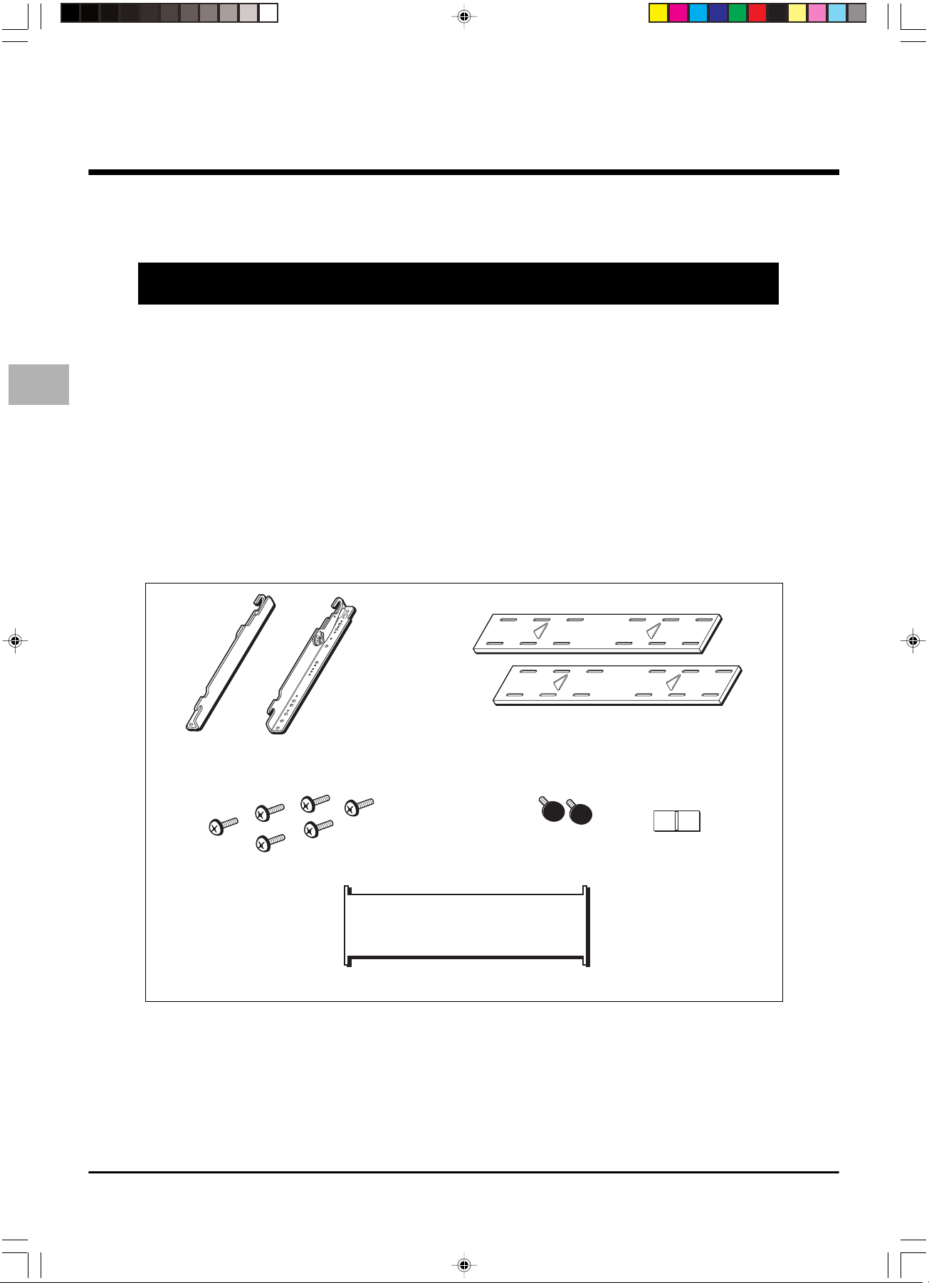
Checking the package contents
Check to make sure the following items are included in the delivered package. If any of these
items are missing or defective, contact your dealer immediately.
Plasma mounting brackets (left and right)
Wall mount plates
Safety knobs - 2
Plasma mounting bracket screws (M8 x 20) - 6
Cardboard wall plate positioning template - 1
Important: Screws for installing the wall mount on the wall are NOT supplied. The type of screws to be used depends on the
type of wall (wood, cement, etc.).
Level - 1
Specifications
Model: ACC914
Weight: 7 kg
48 kg when supporting plasma display
2
Page 3

Installation
Installing the Mounting Brackets
1. Carefully turn the plasma monitor over so that the back of it is facing you and place it on a soft and flat surface.
2. Locate the mounting points on the back of the monitor (see figure 1).
3. Secure the left and right plasma mounting brackets to the monitor using the supplied plasma mounting bracket screws (see
figure 2).
Important: Make sure the upper hooks’ mounting screws, nuts, and reference arrows are facing to the left and right outside
edges of the monitor.
Note: Do not over tighten the mounting bracket screws, as you could damage the monitor’s internal mounting threads.
4. Loosen the nut and screw on each mounting bracket just enough so that you can tilt the monitor out from the wall. Be
careful not to make the hooks too loose, or they’ll become unstable.
1
2
EN
Upper hook
3
Lower hook
Mounting points on the plasma mounting bracket
Figure 1
Plasma mounting brackets
Plasma mounting bracket screw
Figure 2
3
Page 4

EN
Installation
Measuring for Monitor Placement on the Wall
1. Determine the desired wall location and its ability to properly support the weight of the monitor and wall mount assembly.
2. Determine how high you want the bottom edge of the monitor to be.
3. Temporarily slide the round steel rod portion of one of the wall mount plates fully into the bottom hooks of the installed
plasma mounting brackets (see figure 3).
4. Measure the distance between the bottom outside edge of the plasma monitor and the bottom outside edge of the lower
wall mount plate. Add the desired bottom edge height of the monitor to this measurement to determine the correct
mounting height of the lower wall mount plate (see figure 4). Remove the wall mount plate.
Example: The overall desired height for the bottom outside of the monitor is 150 cm. The difference between the bottom
edge of the monitor and the bottom edge of the lower wall mount plate fully installed in the lower hooks of the brackets is
10 cm. This means the bottom outside edge of the lower wall mount plate should be placed 160 cm from the floor
(150 + 10 = 160).
5. Locate and mark the dual 40 cm or 60 cm hole centres closest to the desired plasma placement area.
Note: The wall mount plate provides you with three 40 cm hole patterns and one 60 cm hole pattern to assist you in your installation.
6. Measure up from the floor the proper distance to the bottom edge of the lower wall mount plate, and mark a level reference
line on the wall.
7. Place the bottom edge of the lower wall mount plate on the reference line and mark the 4 wall plate screw mounting points
through the wall mount plate slots on the wall. Install the bottom wall mount plate, with the wall mount plate reference
arrow pointing up to the wall, using the supplied level, and screws appropriate for this type of wall.
Wall mount plate
Figure 3
MEASURE & NOTE
Figure 4
4
Bottom of the wall mount plate
Bottom of the monitor
Page 5

Installation
Installing the Wall Mount Plates
Important:
The arrows on the wall mount plates must be facing up prior to installation.
Also, the rounded part of each wall mount plate should be on the bottom.
1. With the lower wall mount plate securely installed and level with the floor, place the cardboard positioning template over the
top and outside edges of the lower wall mount plate.
2. Place the bottom and outside edges of the upper wall mount plate into the top portion of the template, and mark the
duplicate set of mounting points for the upper wall mount plate to the wall (see figure 5).
3. Secure the upper wall mount plate to the wall in the same manner as the lower plate using screws appropriate for this type
of wall. With the two wall mount plates properly secured to the wall, use the positioning template to recheck the separation
between the upper and lower plates.
Top wall mount plate
EN
Bottom wall mount plate
SET ON TOP OF
TEMPLATE AND SECURE
SET ON TOP OF SECURED
267 mm
WALL PLATE
PLASMA LINE
40 cm
60 cm
MEASUREMENT FROM PREVIOUS PAGE
Figure 5
Cardboard wall mount plate
positioning template
5
Page 6

EN
Installation
Installing the Monitor
1. With the upper hooks on the plasma brackets in the flat wall position, raise the plasma monitor (2 people minimum
recommended) and place the monitor flat against wall, with the upper and lower plasma bracket attaching hooks slightly
higher than the steel receiving rods of the upper and lower wall mount plates.
2. With the plasma reasonably level, lower it until the monitor brackets’ hooks are fully attached to the upper and lower wall
mount plate steel rods.
3. Gently pull the left and right upper edges of the monitor to extend it to its maximum 10° tilt, screw in one safety knob on
each side of the mounting brackets so that they are snug.
Important:
Make sure to install the safety knobs, as they prevent the brackets from detaching from the wall mount plates.
Safety knob
WALL STRUCTURE
WALL STRUCTURE
CLEARANCE
Figure 6
Note: To remove the monitor from the
wall, simply extend the monitor to its
maximum tilt range, remove the two
safety knobs, push the monitor back
to its flat wall position, and lift the
unit up and out from the wall (2
people minimum recommended).
Final Adjustments
Once the monitor is firmly mounted on the wall, you still can move it from side to side to optimize the final position by gently
sliding the unit on the steel rods of the wall mount plate.
0°
22 mm
LATERAL MOVEMENT
Notes:
- When the monitor brackets hooks are fully installed into the upper and lower wall mount plate steel rods and the plasma is flat, there is a 22 mm
gap from the top of the rod to the end of the hook. This is to compensate for tilting.
- The 8 mm nuts are used for the coarse tension adjustment, while the 5 mm screws are for the fine tension adjustment.
Figure 7
6
 Loading...