

Page 1
SERVICE MANUAL
DOCUMENTATION TECHNIQUE
TECHNISCHE DOKUMENTATION
DOCUMENTAZIONE TECNICA
DOCUMENTACION TECNICA
No copying, translation, modification on other use authorized. All rights reserved worldwide. • Tous droits de reproduction, de traduction, d'adaptation et d'exécution réservés pour tous les pays. • Sämtliche Urheberrechte an diesen Texten und Zeichnungen stehen uns zu. Nachdrucke,
Vervielfältigungen - auch auszugsweise - nur mit unserer vorherigen Zustimmung zulässig. Alle Rechte vorbehalten. • I diritti di riproduzione, di traduzione, e esecuzione sono riservati per tutti i paesi. • Derechos de reproduccion, de traduccion, de adaptacion y de ejecucion reservados para todos los paises.
WARNING : Before servicing this chassis please read the safety recommendations.
ATTENTION : Avant toute intervention sur ce châssis, lire les recommandations de sécurité.
ACHTUNG : Vor jedem Eingriff auf diesem Chassis, die Sicherheitsvorschriften lesen.
ATTENZIONE : Prima di intervenire sullo chassis, leggere le norme di sicurezza.
IMPORTANTE : Antes de cualquier intervención, leer las recomendaciones de seguridad.
Code : 351 530 30 - 0301 / 00M - Print.
42WS90E
42WS90E2
TV
Plasma
Page 2
MAIN
FRANÇAIS ESPAÑOLDEUTSCHENGLISH ITALIANO
1
2
3
4
5
6
7
8
9
10
11
12
13
14
15
16
17
18
19
20
21
NC
NC
21
17
19
15
13
20
18
16
14
12
11
9
10
8
7
5
3
1
6
4
2
NC
AUDIO "R"
AUDIO "R"
AUDIO "L"
NOTE :
... etc. identifies each
pcb module.
AUDIO "D"
AUDIO "D"
AUDIO "G"
AUDIO
"BLEU"
AUDIO "G" MONO
"BLEU"
COMMUT. LENTE
"VERT"
"VERT"
"ROUGE"
COMMUT. RAPIDE
COMMUT. RAPIDE
VIDEO
VIDEO SYNCHRO
BLINDAGE PRISE
AUDIO "R"
AUDIO "R"
AUDIO "L"
AUDIO
"BLAU"
AUDIO "L" MONO
"BLAU"
AV
UMSCHALTUNG
"GRÜN"
"GRÜN"
"ROT"
AUSTASTUNG
AUSTASTUNG
VIDEO
VIDEO ODER
SYNCHRO
ABSCHIRMUNG
DES STECKERS
AUDIO "D"
AUDIO "D"
AUDIO "I"
AUDIO
"AZUL"
AUDIO "I" MONO
AZUL
"CONMUTACION
LENTA"
"VERDE"
"VERDE"
"ROJA"
"CONMUTACION
RAPIDA"
"CONMUTACION
RAPIDA"
VIDEO
VIDEO O SINCRO
BLINDAJE
DEL ENCHUFE
AUDIO "D"
AUDIO "D"
AUDIO "S"
AUDIO
"BLU"
AUDIO "S" MONO
BLU
"COMMUTAZIONE
LENTA"
"VERDE"
"VERDE"
"ROSSO"
"COMMUTAZIONE
RAPIDA"
"COMMUTAZIONE
RAPIDA"
VIDEO
VIDEO O SINCRO
INVOLUCRO METAL-
LICO DELLA PRESA
AUDIO "L" MONO
"BLUE"
"GREEN"
"GREEN"
"RED"
"ROUGE" "ROT" "ROJA""ROSSO""RED"
SLOW SWITCH
FAST SWITCH
VIDEO
VIDEO VIDEO VIDEOVIDEOVIDEO
PLUG SCREEN
BOX
VIDEO OR "SYNC"
FAST SWITCH
AUDIO
"BLUE"
: OUTPUT - SORTIE - AUSGANG - USCITA - SALIDA •
: EARTH - MASSE - MASSE - MASSA - MASA
MAIN
NOTE :
... etc. repères des
platines constituant l'appareil.
MAIN
NOTA :
... etc. marcas de las
placas que constituyen el
aparato.
MAIN
NOTA :
... ecc. sigla delle
piastre dell' apparecchio.
MAIN
HINWEIS :
... usw. Kennzeichnung
der Platinen, aus denen das
Gerät zusammengesetzt ist.
: INPUT - ENTRÉE - EINGANG - ENTRATA - ENTRADA •
Indicates critical safety components, and identical components should be used for replacement. Only then can the
operational safety be garanteed.
Le remplacement des éléments de sécurité (repérés avec le symbole ) par des composants non homologués selon la
Norme CEI 65 entraine la non-conformité de l'appareil. Dans ce cas, la responsabilité du fabricant n'est plus engagée.
Wenn Sicherheitsteile (mit dem Symbol gekennzeichnet) nicht durch Original - Ersatzteile ersetzt werden, erlischt die
Haftung des Herstellers.
La sostituzione dei componenti di sicurezza (evidenziati con il segno ) con componenti non omologati secondo la
norma CEI 65 comporta la non conformitá dell'apparecchio. In tal caso è "esclusa la responsabilità " del costruttore.
La sustitución de elementos de seguridad (marcados con el simbolo ) por componentes no homologados segun la
norma CEI 65, provoca la no conformidad del aparato. En ese caso, el fabricante cesa de ser responsable.
MEASUREMENT CONDITIONS - CONDITIONS DE MESURES - MESSBEDINGUNGEN
CONDIZIONI DI MISURA - CONDICIONES DE MEDIDAS
RICEVITORE :
In UHF, livello d'entrata 1 mV, monoscopio barre :
- PAL, norma G. bianco 100%.
Via SCART, livello d'entrata 1 Vpp, monoscopio barre :
Colore, Contrasto, Luminositá media, Suono minimo.
Programma selezionato PR 01.
Tensioni continue rilevate rispetto alla massa con un voltmetro digitale.
RECEIVER :
On UHF,input level : 1 mV, bar test pattern :
- PAL, I standard, 100% white.
Via the scart socket, input level : 1 Vpp, bar test pattern :
Colour, contrast and brightness at mid-position, sound at minimum.
Programme selected : PR 01.
DC voltages measured between the point and earth using a digital
voltmeter.
EMPFÄNGER :
Bei UHF Eingangspegel 1 mV, Farbbalken :
- PAL, Norm G, Weiss 100%.
Über die Scartbuchse : Eingangspegel 1 Vss, Farbbalken :
Farbe, Kontrast, Helligkeit in der Mitte des Bereichs, Ton auf Minimum.
Zugeordnetes Programm PR 01.
Gleichspannungen mit einem digitalen Voltmeter zur Masse gemessen.
RECEPTEUR :
En UHF, niveau d'entrée 1 mV mire de barres
- SECAM, Norm L, Blanc 100%.
Par la prise Péritélévision, niveau d'entrée 1 Vcc, mire de barres .
Couleur, contraste, lumière à mi-course, son minimum.
Programme affecté PR 01.
Tensions continues relevées par rapport à la masse avec un
voltmètre numérique.
RECEPTOR :
En UHF, nivel de entrada 1 mV, mira de barras :
- PAL, norma G, blanco 100%.
Por la toma Peritelevision, nivel de entrada 1 Vpp mira de barra.
Color, Contraste, luz a mitad de carrera, Sonido minimo.
Programa afectado PR 01.
Tensiones continuas marcadas en relacion a la masa con un voltimetro digital.
Do not disconnect modules when they are energized!
Repairs on power supply section are to be carried out only with isolating transformer.
Ne pas retirer les modules lorsqu' ils sont sous tension. N'effectuer les travaux de maintenance sur la partie reliée
au secteur (Switch Mode) qu'au travers d'un transformateur d'isolement.
Module nicht bei eingeschaltetem Gerät entfernen!
Servicearbeiten am Netzteil nur unter Verwendung eines Regeltrenntrafos durchführen.
Non scollegare le piastre quando sono alimentate!
Per le riparazioni sulla sezione alimentatore, utilizzare un trasformatore isolatore.
No desconectar los módulos cuando están activados. Las reparaciones en la sección de alimentación de energía
deben ser ejecutadas solamente con un transformador de separación.
Page 3

First issue 03 / 01 3
Page Page
DISASSEMBLY
Removing the back panel . . . . . . . . . . . . . . . . . . . 4
Removing the terminal panels . . . . . . . . . . . . . . . 4
Removing the AUDIO and VIDEO modules . . . . . . 5
Removing the POWER module . . . . . . . . . . . . . . . 5
Removing the fan . . . . . . . . . . . . . . . . . . . . . . . . . 6
Removing the ANALOG module . . . . . . . . . . . . . . 6
WIRE LOCATION . . . . . . . . . . . . . . . . . . . . . . . . . . . . . 7
DIAGNOSTIC . . . . . . . . . . . . . . . . . . . . . . . . . . . . . . . . . 8
VIDEO TROUBLESHOOTING
No video screen display . . . . . . . . . . . . . . . . . . . .13
No RGB /PC screen display . . . . . . . . . . . . . . . . .14
No HD/DVD screen display . . . . . . . . . . . . . . . . . .15
No RGB signal . . . . . . . . . . . . . . . . . . . . . . . . . . .15
No NTSC . . . . . . . . . . . . . . . . . . . . . . . . . . . . . . .16
No PAL . . . . . . . . . . . . . . . . . . . . . . . . . . . . . . . . 17
No display ANALOG module analysis . . . . . . . . . 18
Synchonisation trouble . . . . . . . . . . . . . . . . . . . . .19
AUDIO TROUBLESHOOTING
No audio signal from SP output . . . . . . . . . . . . . .20
No audio signal from AUDIO output . . . . . . . . . .20
ADJUSTMENT . . . . . . . . . . . . . . . . . . . . . . . . . . . . . . 21
Video level . . . . . . . . . . . . . . . . . . . . . . . . . . . . . 22
Sub-brightness . . . . . . . . . . . . . . . . . . . . . . . . . . 24
Sub-contrast . . . . . . . . . . . . . . . . . . . . . . . . . . . . 24
Video screen position . . . . . . . . . . . . . . . . . . . . . 24
RGB screen position . . . . . . . . . . . . . . . . . . . . . . 24
Power . . . . . . . . . . . . . . . . . . . . . . . . . . . . . . . . . 24
ADJUSTMENT LOCATION
ANALOG module
(42WS90E) . . . . . . . . . . . . . . . . . 25
ANALOG module (42WS90E2) . . . . . . . . . . . . . . . . . 26
VIDEO module . . . . . . . . . . . . . . . . . . . . . . . . . . 27
AUDIO module . . . . . . . . . . . . . . . . . . . . . . . . . . .27
POWER module . . . . . . . . . . . . . . . . . . . . . . . . . 28
BLOCK DIAGRAMS
I/O module (42WS90E) . . . . . . . . . . . . . . . . . . . . . . 29
ANALOG module
(42WS90E) . . . . . . . . . . . . . . . . . 30
ANALOG module (42WS90E2) . . . . . . . . . . . . . . . . 31
VIDEO module . . . . . . . . . . . . . . . . . . . . . . . . . . 32
AUDIO module . . . . . . . . . . . . . . . . . . . . . . . . . . 33
POWER module . . . . . . . . . . . . . . . . . . . . . . . . . 34
CONTENTS
Page 4
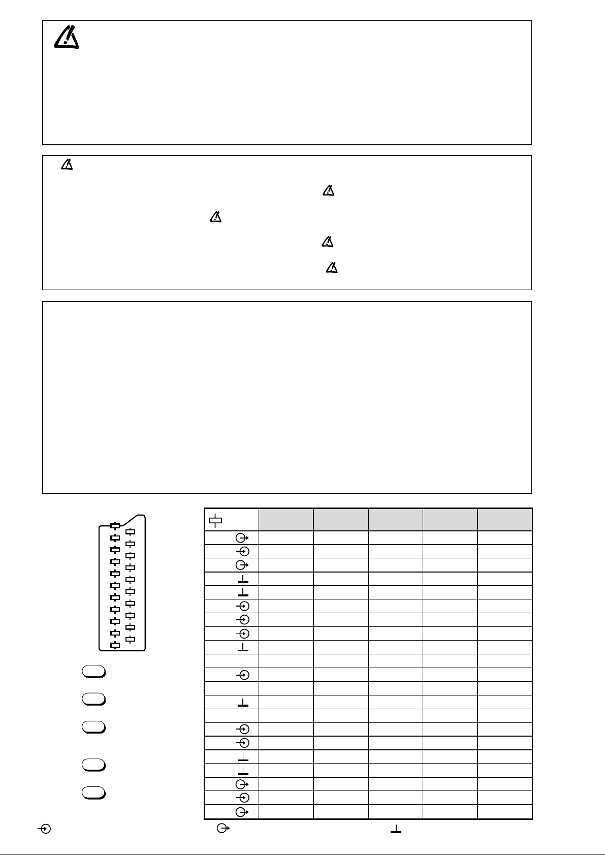
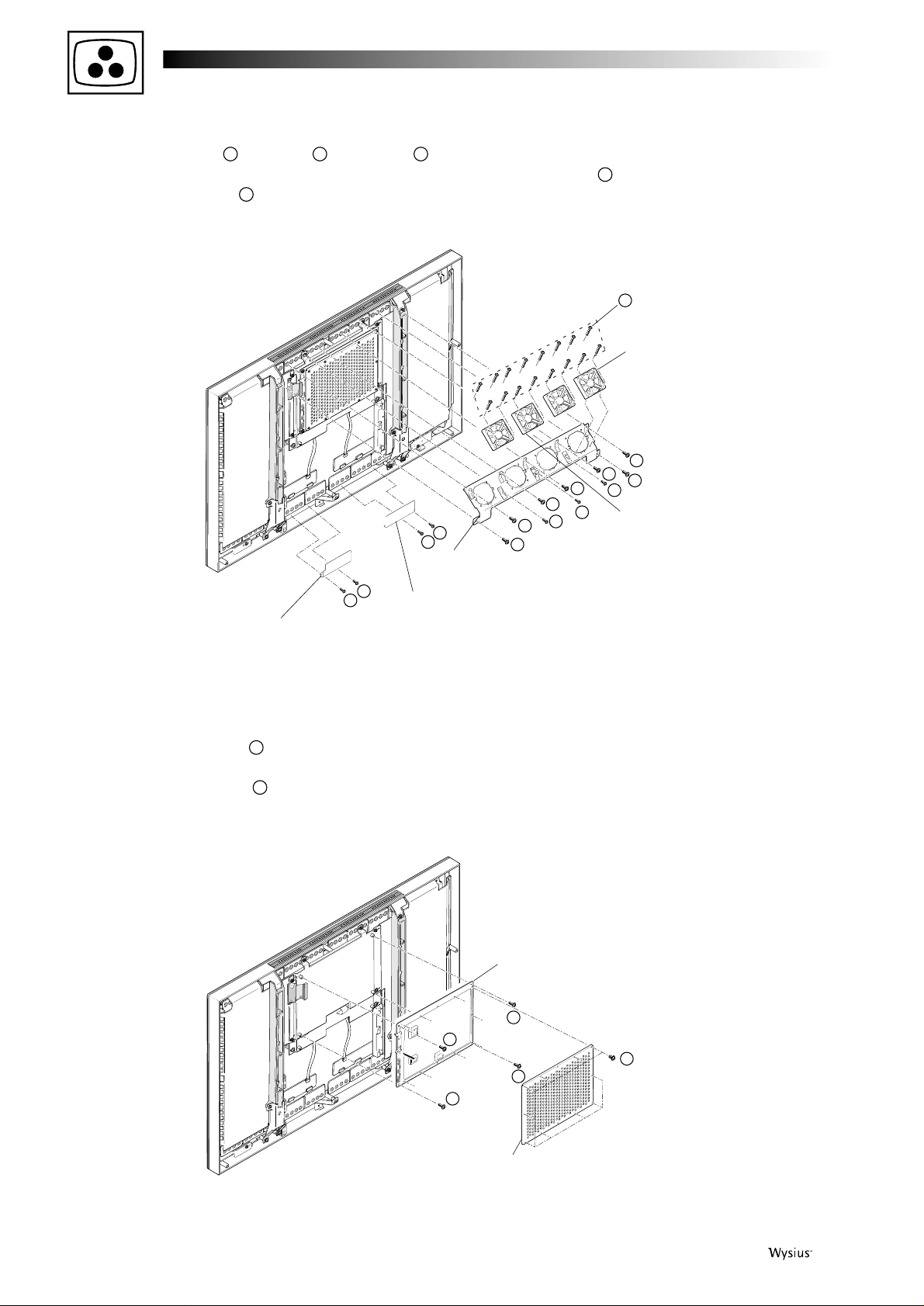
DISASSEMBLING THE MODULES
2. Removing the terminal panels (S), (V), R TERM, L TERM, S-I/O and VIDEO I/O modules
4 First issue 03 /01
1. Removing the back panel
- Remove the 17 screws , the 8 screws and the screw ,
- Remove the back panel.
- Remove the 2 screws of the terminal panel (S) on the
left side of the set and remove the 2 screws of the
terminal panel (V) on the right side of the set,
- Remove the terminal panels (S) and (V),
- Pull out the S-I/O module and the VIDEO I/O module from
the terminal panels,
.
- Remove the 2 screws on the left side of the set and
take out the R-TERM module,
- Remove the 2 screws on the right side of the set and
take out the L-TERM module.
07
0605040302
01
BACK PANEL
01
01
01
01
01
01
01
01
01
01
01
01
01
01
01
01
01
02
02
02
02
02
02
02
02
03
VIDEO I/O MODULE
L TERM MODULE
TERMINAL PANEL (V)
TERMINAL BRACKET
SHIELD CASE (V-I/O) A
SHIELD CASE (S-I/O)
S-I/O MODULE
TERMINAL BRACKET
TERMINAL PANEL (S)
R TERM
MODULE
05
05
04
06
07
Page 5
First issue 03 / 01 5
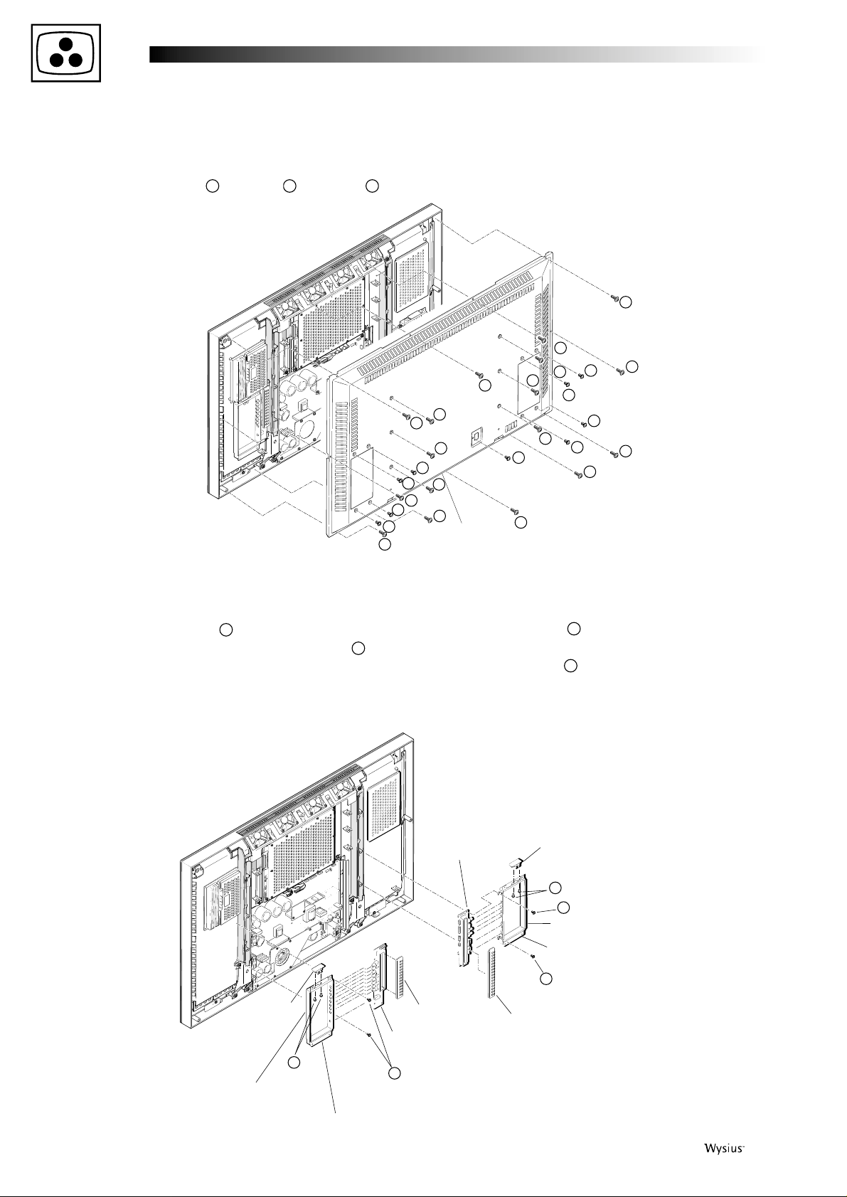
3. Removing the AUDIO and VIDEO modules
- Remove the 4 screws and take out AUDIO module,
- Remove the 4 screws and take out VIDEO module.
4. Removing the power module
- Remove the 6 screws and take out the power unit.
10
09
08
AUDIO MODULE
SHIELD CASE (AUD)
VIDEO MODULE
SHIELD CASE (VID)
08
08
08
08
09
09
09
09
POWER UNIT
10
10
10
10
10
10
Page 6
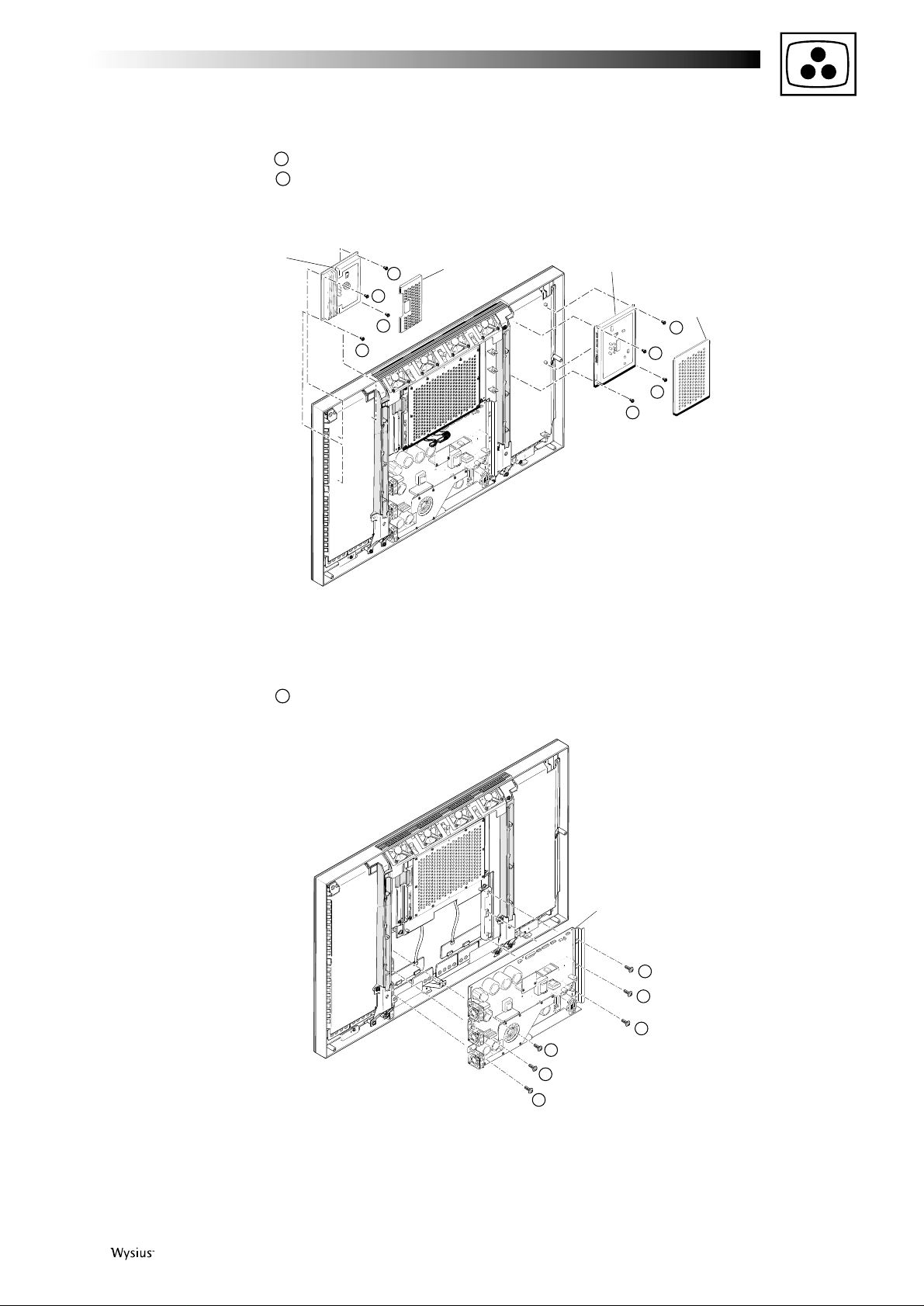
5. Removing the bracket (fan)/DC fan
-
Remove the 7 screws , the 2 screws , and the screw ,
- Take out the bracket (fan),
- Remove the 16 screws and take out the DC fan from
6. Removing the shield case (ANA)A/ANALOG module
- Remove the 10 screws and take out the shield case
(ANA) A,
- Remove the 4 screws and take out the ANALOG
module.
the bracket (fan),
- Remove the 4 screws and take out the grand boards L and R
15
17
16
141312
11
DC FAN
DC FAN
BRACKET (FAN)
GRAND BOARD R
GRAND BOARD L
B
B
A
A
11
11
11
11
11
11
11
15
15
15
15
12
12
14
13
ANALOG MODULE
SHIELD CASE (ANA) A
(10 pcs.)
16
17
17
17
17
6 First issue 03 /01
Page 7
First issue 03 / 01 7
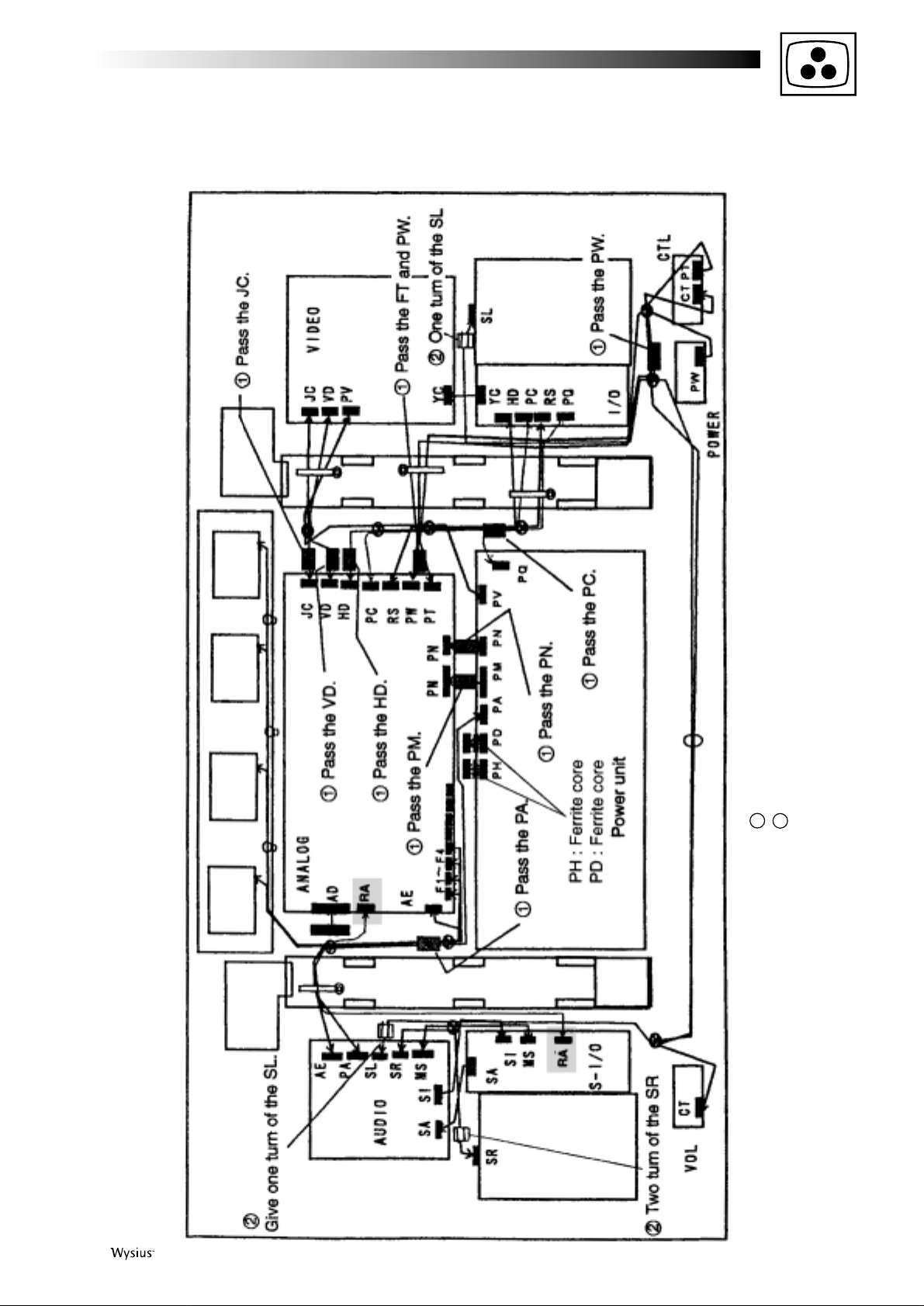
WIRE LOCATION
After replacement of the modules refer to the below diagram to mount ferrites and connect the modules again.
Note: “RA” connectors are only fitted in 42WS90E2.
ferrite core : ZCAT2032 930 (code 351 571 10)
ESD-R-19 (code 351 571 20)
2
1
Page 8
8 First issue 03 /01
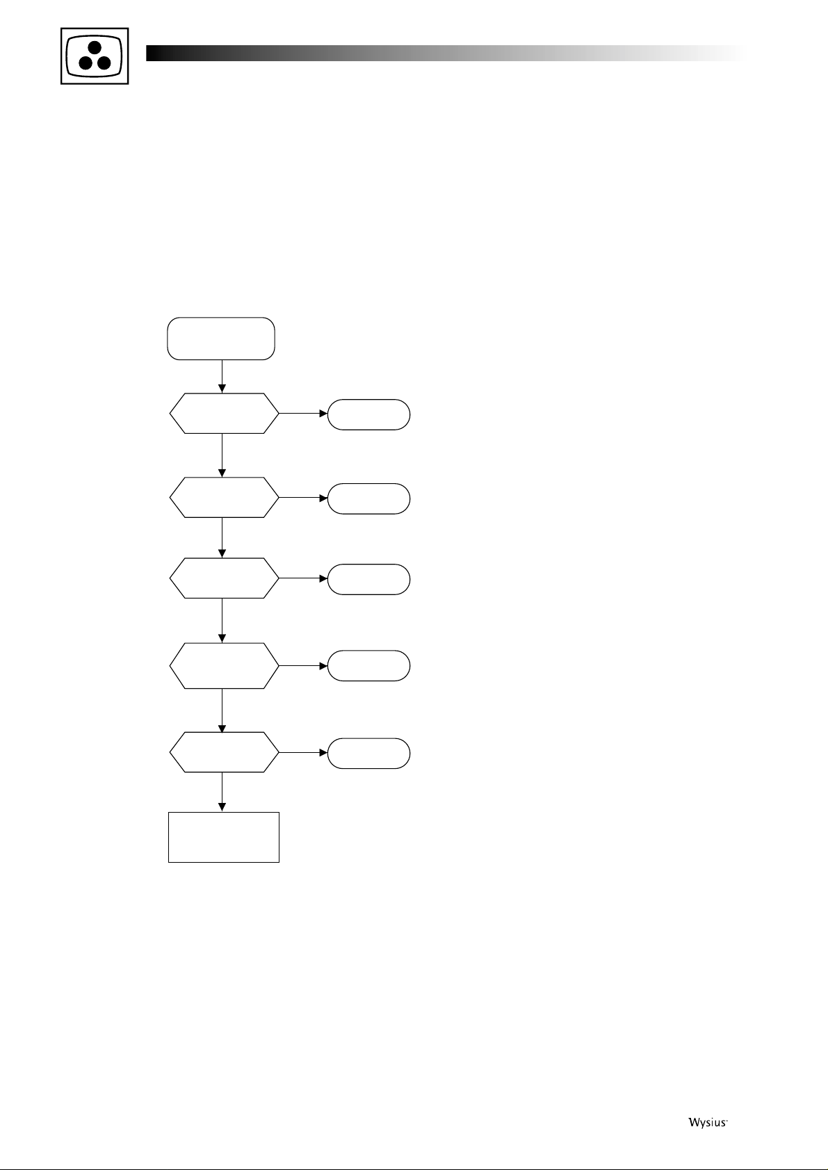
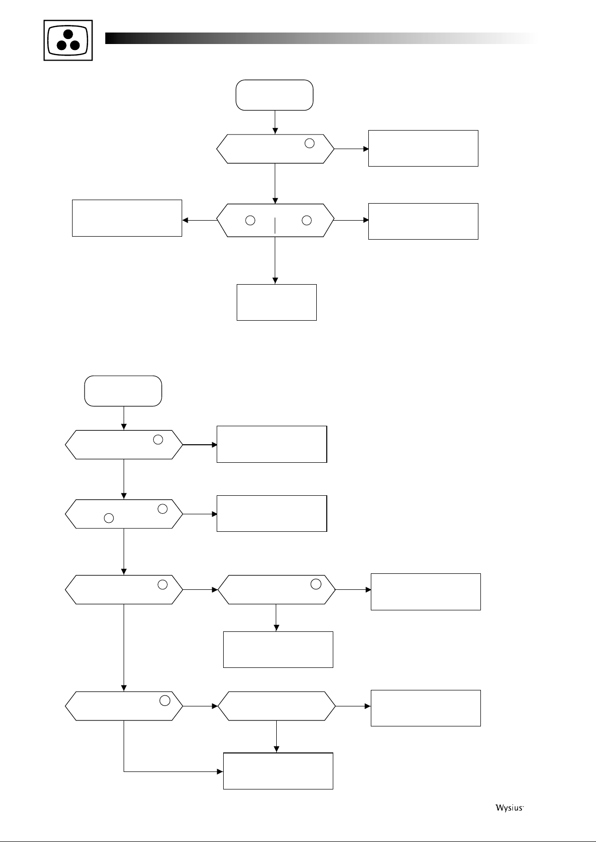
DIAGNOSTIC
The power LED located on the front of the display is a bicolour LED wich indicates the operating status including the normal, standby
and three error detections
42WS90E-42WS90E2
No energization
of POWER unit
Is the power
LED lit ?
See page 9
Is the power LED
flashing green?
See page 10
Is the power LED
lighting green?
The power LED
is lighting red :
Stand-by mode
See page 12
Is the power LED
flashing red?
See page 11
Is the power
LED flashing green
and red?
See page 12
No
No
Yes
Yes
No
Yes
No
Yes
No
Yes
Page 9
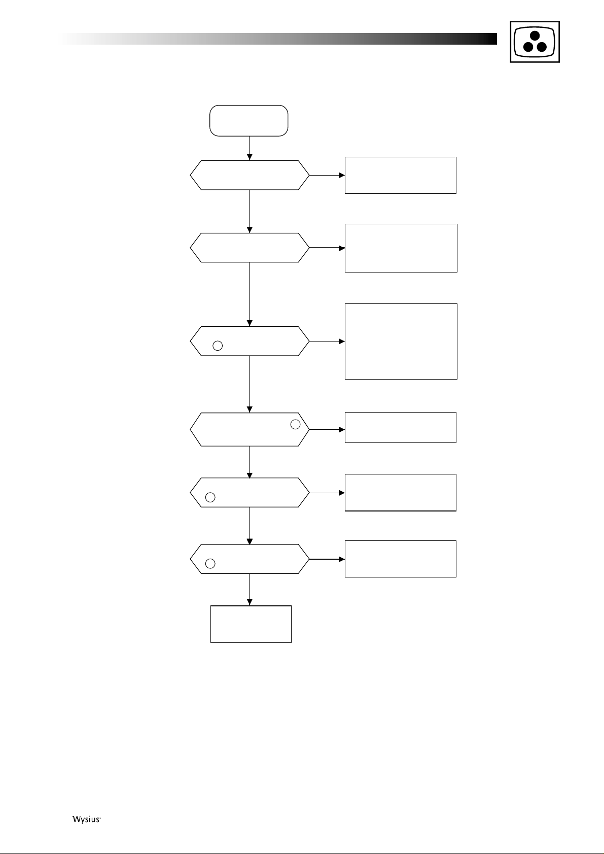
First issue 03 / 01 9
Power LED
unlit
No
No
Yes
Yes
No
Yes
No
Yes
No
Yes
Is the power plug correctly
connected to the wall outlet?
Rearrange the power plug
connection correctly.
Is there AC 100V behind
the fuses F1 and F2?
Fuses F1 and F2 have blown
out. Replace the fuses. If they
blow out again, the POWER
unit is out of order
Is there M+14V output at
Pin 1 of the PM connector?
Disconnect the PM and PQ
connectors from one after
another. If there is M+14V
output, the circuit beyond the
connec
tors is out of order.
If there is no
output, the
POWER unit is out of order.
Is there +5V output at Pin 2
of IC6805 (ANALOG module)?
Failure in the CTL module
Is there +5V output at Pin
5 of the PW connector?
Failure in +5V line. Check
the POWER module
Failure in the
POWER module
No
Yes
Failure in the
ANALOG module
Is there +5V output at Pin
3 of the PW connector?
42WS90E-42WS90E2
Page 10
10 First issue 03 /01
No
The power LED
is flashing green
No
YesYes
Yes
No
Failure in the
ANALOG module
Failure in the
POWER unit
Is
0V observed at
pin 1 of pin 2 of
IC6553? IC6553?
Failure in fan's peripheral
area of the set
Failure in the
ANALOG module
Is 0V observed at Pin 4 of
IC6800 (ANALOG module)?
The power LED
is flashing green
No
Yes
Failure in the
ANALOG module
Is 0V observed at Pin 3 of
IC6800 (ANALOG module)?
No
Yes
Failure in fan's peripheral
area of the set
Failure in the
ANALOG module
Is 0V observed at Pin 2
or 5 of IC6807?
No
Yes
Yes
Is 0V observed at Pin 13
of the PM connector?
No
Yes
No
Yes
Is FL6074 normal?
Failure in the
POWER module
Is 0V observed at Pin 9
of IC6807 ?
Is 12V observed at Pin 11
of PM connector?
Failure in the
ANALOG module
Failure in the
POWER module
42WS90E
42WS90E2
Page 11
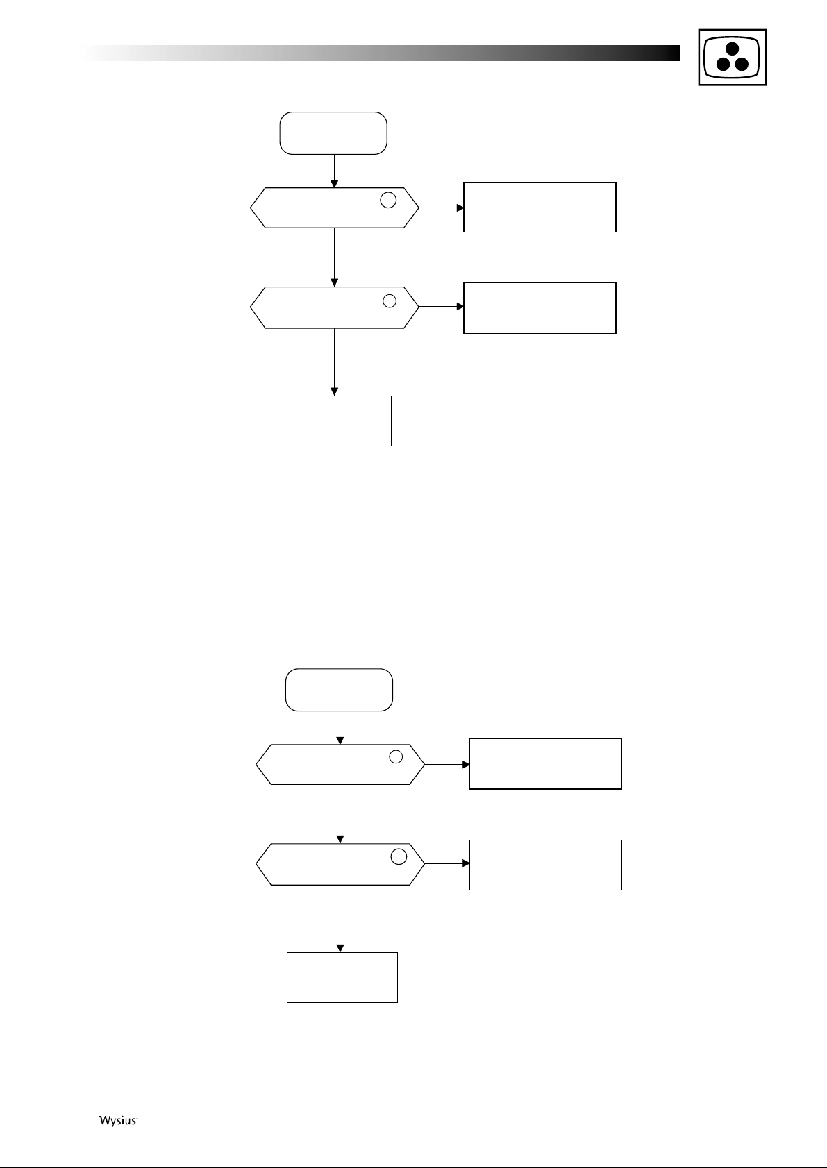
First issue 03 / 01 11
The power LED
is flashing red
No
Yes
Yes
No
Failure in the
ANALOG module
Is
0V observed at
pin 5
of IC6808
(ANALOG module)
?
Failure in the
ANALOG module
Is 0V observed at Pin 57
of IC6800 (ANALOG module)?
Failure in the
POWER unit
The power LED
is flashing red
No
Yes
Yes
No
Failure in the
ANALOG module
Is
0V observed at
pin 13
of IC6808
(ANALOG module)
?
Failure in the
ANALOG module
Is 0V observed at Pin 4
of IC6800 (ANALOG module)?
Failure in the
POWER unit
42WS90E
42WS90E2
Page 12

12 First issue 03 /01
The power LED is fla-
shing red and green
No
Yes
Failure in the
ANALOG module
Is 0V observed at Pin 14 of
IC6800 (ANALOG module)?
Failure in the
PDP module
In the case of green and red flashing, the power supply
cannot be reset with the OFF/ON operation at the mains
power supply, remote control, and wall outlet.
For the alarm reset, keep pressing the input changeover key
of the main unit and move the mains power supply to the
"ON" position at the main unit. While doing so, it is
necessary to keep pressing the input changeover key of the
main unit for more than two seconds.In the case of green
and red flashing, the power supply cannot be reset with the
OFF/ON operation at the mains power supply, remote
control, and wall outlet.
42WS90E-42WS90E2
42WS90E-42WS90E2
The power LED
is lighting green
Is "H" maintained at Pins 2
and 3 of the PM connector?
Is "H" maintained at Pin
7 of the PH connector?
Is power supply available
when SW1* is turned OFF?
* POWER unit: HV system is OFF
Yes
Yes
Yes
No
No
Disconnect the PV, PQ, PN
and PA connectors one after
another (others kept connected)
No
and confirm that the power
supply is available. If it is not
available, the POWER unit is
out of order. Else, the circuit
of the disconnected connector
is out of order.
Failure in the
ANALOG module
Failure in the peripheral
area of PDP module
Failure in the PDP
module and the
POWER unit
Page 13

First issue 03 / 01 13
VIDEO TROUBLESHOOTING
No
No video
screen display
No
Yes
Enter a color bar
signal input
No
Yes
Failure in the
VIDEO I/O module
No
Yes
Yes
No
Yes
No
Yes
Failure in signal source
Failure in the
ANALOG module
See page 18
See page 18
Is there on-screen
display of VIDEO?
Is there a video signal at
TP1001 (VIDEO I/O module)?
With the signal line discon-
nected,
is there a video signal
at the signal line terminal?
With the YC connector
disconnected, is there a
video signal at TP1025?
Is there a rectangular wave-
form signal of 5Vp-p at pins 2
and 3 of the IC connector?
No
Yes
Failure in the
VIDEO I/O module
Is there a Y signal input at
pins 1 and 9 of IC5006?
Is there a video signal at
Pins 1 , 3 and 5 of the VD
connector in VIDEO module?
Failure in the
VIDEO module
42WS90E-42WS90E2
Page 14

14 First issue 03 /01
No
No RGB / PC
screen display
No
Yes
No
Yes
Failure in the
VIDEO I/O module
No
Yes
Yes
No
Yes
No
Yes
Failure in signal line
Failure in the
ANALOG module
See page 18
See page 18
Is there on-screen
display of "PC"?
Is the LED litting green?
Is there a video signal at
TP1007, TP1008, and
TP1009?
Failure in the
ANALOG module
Failure in signal line
Enter a VGA or SVGA
color bar signal input.
With the signal line discon-
nected,
is there a video signal
at the signal line terminal?
Is there horizontal sync at
Pin 13 of M1006 socket, or
vertical sync at Pin 14 ?
Is there horizontal sync at
Pin 8 of "PC" connector,
or vertical sync at Pin 10 ?
42WS90E-42WS90E2
Page 15

First issue 03 / 01 15
No
No HD / DVD
screen display
No
Yes
Enter a color bar
signal input
Failure in the
ANALOG module
No
Yes
Yes
Failure in signal source
See page 18
See page 18
Is there on-screen
display of "HD" or "DVD"?
Is there a video signal at
TP1004 (VIDEO I/O module)?
With the signal line discon-
nected,
is there a video signal
at the signal line terminal?
No RGB
signal
No
Yes
Failure in the
VIDEO module
Failure in the
ANALOG module
Is RGB signal available at Pins
1 , 3 , 5 of the VD connector?
42WS90E-42WS90E2
42WS90E-42WS90E2
Page 16

16 First issue 03 /01
No video in
NTSC mode
No
Yes
No
Yes
Failure in the
VIDEO module
No
Yes
A
Is Y signal available
at TP9003?
Is there a video signal
at TP9007?
Failure in the
VIDEO I/O module
No NTSC color
generation
No
Yes
No
Yes
Failure in the
VIDEO module
No
Yes
A
Is C signal available
at TP9004?
Is there a video signal at Pin
1 of the YC connector?
Is C signal available
at Pin 13 of IC5008?
Is C signal available
at Pin 14 of IC5006?
42WS90E-42WS90E2
Page 17

First issue 03 / 01 17
No video in
PAL mode
No
Yes
No
Yes
Failure in the
VIDEO module
No
Yes
B
Is Y signal available
at TP5004?
Is there a video signal
at TP5030?
Failure in the
VIDEO I/O module
No PAL color
generation
No
Yes
No
Yes
Failure in the
VIDEO module
No
Yes
B
Is C signal available
at TP9005?
Is there a video signal at Pin
1 of the YC connector?
Is C signal available
at Pin 13 of ICC5008?
Is C signal available
at Pin 16 of ICC5006?
42WS90E-42WS90E2
Page 18

18 First issue 03 /01
No display, ANALOG
module analysis
No
Yes
No
Yes
No
Yes
Failure in AD cable
No
Yes
No
Yes
No
Yes
No
Yes
Failure in the
ANALOG module
No
Yes
End
Is there a video signal
at TP6139, TP6140
and TP6141?
Is there a signal of 5Vp-p at Pins
1 ~ 47 of the AD connector
(odd-numbers only)?
Is there a clock signal at Pin
49 of the AD connector?
Is normal display available
after replacement of
ANALOG module?
Is the link of AD
connector correct?
Make correct connections
Are the PD and PH con-
nectors correctly connected?
Is there a signal of 5Vp-p at
Pin 51 (H-SYNC) and Pin 53
(V-SYNC) of the AD connector
and the "L" signal at Pin 76?
Refer to No energization
of POWER circuit.
Failure in the PDP module
Are there normal outputs of
180V, 80V
, and D+5V in
the POWER unit?
42WS90E-42WS90E2
Page 19

First issue 03 / 01 19
Synchronisation
trouble
No
Yes
No
Yes
No
Yes
No
Yes
No
Yes
Failure in the
ANALOG module
Failure in the
VIDEO I/O module
No
Yes
Is it a VIDEO input?
NoYes
Yes
No
No
Yes
Is there a video signal at TP1025?
Is the link of AD
connector correct?
Failure in the AD cable
Failure in the PDP module
Replace ANALOG module
Enter a color bar
signal input
Is normal display available
after replacement of ANALOG
module?
Is it a HD/DVD input?
Is there a synchro. signal at Pins
8 and 10 of the PC connector?
Is there a video signal at Pin
2 of the HD connector?
Is there a synchro. signal at Pins
7 and 9 of the VD connector?
Are there a clock signal syn-
chronized with the input signal,
a horizontal synchro. signal
and a vertical synchro. signal, res-
pectively at Pins 49 , 51 and
53 of the AD connector?
42WS90E-42WS90E2
Page 20

20 First issue 03 /01
AUDIO TROUBLESHOOTING
No audio signal
from SP output
Yes
Yes
No
No
Failure in the
AUDIO module
Is audio signal available at
pins
1 , 3 , 4 , 6 , 8 , 10 of IC4001?
Failure in the
SOUND I/O module
Is audio signal available at
at TP3001 and TP3002?
Check each phono
pin output
No audio signal
from AUDIO out
No
Yes
Yes
No
Check the Sub-woofer
Is audio signal available at
at TP4006 and TP4007?
Failure in the
SOUND I/O module
C
C
Is
audio signal available at
Pins
1 and 3 of POMS connector?
42WS90E-42WS90E2
42WS90E-42WS90E2
Page 21

First issue 03 / 01 21
It could be necessary to change the zoom mode in order to
carry out some alignments of the set. Press the "zoom"
button of the remote control. The mode switches as shown
below.
It is necessary to enter the Service Mode in order to carry out
alignment of the set. Most adjustments must be made with
the RCU.
• Using the remote control, press successively the timer ( ),
OK, mute ( ) and timer ( ) buttons.
• The main service menu appears on the screen.
The Service Mode can also be accessed as follow:
• Press the stand-by button of the remote control,
• Switch the power OFF using the button of the keyboard
• While pressing the volume - button, switch the power ON.
• Press the "menu" button to select the menu.
• Press the / buttons to select the menu line.
• Press the / buttons to make adjustments.
NB : the value of the adjustment is memorized automatically.
• To exit the service mode menu press successively, the
timer ( ), OK, mute ( ) and timer ( ) buttons on the
remote control.
ACCESSING SERVICE MODE
3
EXITING FROM SERVICE MODE
2
NAVIGATION INSIDE THE SERVICE MODE
VE200
D CONTROL
NTSC
CONT -18
BRIHT +15
U-COL 74
COLOR + 4
TINT -22
CBRI 120
SERVICE MODE
Before entering the service mode, it could be necessary to
configure the plasma monitor in the On Screen menu.
• Using the remote control, press "menu" button.
• The "main" menu appears on the screen.
• Press the / buttons to select the "setup" line.
• The "setup" menu appears on the screen.
• Select the "color standard" line.
• The "color standard" menu appears on the screen.
• Press the / buttons to select the color standard.
1
ACCESSING COLOR STANDARD
MAIN MENU
OK SELECT EXIT
MENU
PICTURE / AUDIO
SCREEN
OPTIONS
SETUP
SETUP
OK SELECT EXIT
MENU
FREQUENCY
RS 232 MODE
MENU LANGUAGE
COLOR STANDARD
RETURN
COLOR STANDARD
EXIT
MENU
COLOR STANDARD
: 3.58NTSC
RETURN
OSD CONTROLS
ZOOM SEQUENCE
ADJUSTMENTS
ADJUSTMENTS NECESSARY AFTER REPLACEMENT OF MODULES:
- After replacement of ANALOG module, perform the adjusments of "Video level" and "Video screen position".
- After replacement of VIDEO module, perform the adjusments of "video level" and "video screen position".
- After replacement of POWER or PDP module, perform the adjusment of "-180V and +180V" and "+5V".
Replacing another module does not require further adjustment unless abnormal conditions are encountered.
cinema
4/3
16/9full screen
Page 22

22 First issue 03 /01
SERVICE
MODE
"D-CONTROL
NTSC" menu
SERVICE
MODE
"D-CONTROL
NTSC" menu
SERVICE
MODE
"D-CONTROL
NTSC" menu
SERVICE
MODE
"D-CONTROL
PAL" menu
Select standard "3.58NTSC"
No signal at Video input
Video level
L9009
Hz
TP9013
Adjust L9009 : f = 28,6363 MHz
Adjust "C-BRI" line to +120
Adjust "U-COL" line to obtain 900 mVp-p
Adjust "CONT" line to obtain 1.8Vp-p
Adjust "COLOR" line to obtain a blue level :
1.2Vp-p (42WS90E) or 1.4 Vp-p (42WS90E2)
Adjust "TINT" line to obtain a blue level :
1.2Vp-p (42WS90E) or 1.4 Vp-p (42WS90E2)
Line "C-BRI"
VIDEO
Video level
ANALOG
TP6130 (42WS90E)
TP6138 (42WS90E2)
Select standard "AUTO"
No signal at Video input
NTSC grey scale test pattern
Video input
white =100%
black
NTSC colour bar test pattern
Video input
TP6139
(R-OUT)
TP6139
(R-OUT)
TP6140
(B-OUT)
TP6140
(B-OUT)
TP6141
(G-OUT)
900 mVp-p
Pedestal level
Pedestal level
Adjust "BRIHT" line to obtain 600mV DC
Check that Pedestal level is 600 mV, if not perform
adjustment of sub-brightness
TP6140
(B-OUT)
TP6141
(G-OUT)
Check that Pedestal level is 1.8Vp-p, if not perform
adjustment of sub-contrast
Repeat alternatively the "COLOR" and TINT"
adjustments
600 mV
1.8 Vp-p
Adjust "C-BRI" line to +120
Adjust "U-COL" line to obtain 900 mVp-p
Line "C-BRI"
TP6130 (42WS90E)
TP6138 (42WS90E2)
PAL grey scale test pattern
Video input
white =100%
black
TP6139
(R-OUT)
TP6140
(B-OUT)
TP6141
(G-OUT)
900 mVp-p
Pedestal level
Adjust "BRIHT" line to obtain 600mV DC
Check that Pedestal level is 600 mV, if not perform
adjustment of sub-brightness
600 mV
White
Yellow
Cyan
Green
Magenta
Red
Blue
Black
(1.40V)
1.20V
Linearly decreases
From the black to
blue of the signal
Pedestal
Page 23

First issue 03 / 01 23
Video level
Adjust "CONT" line to obtain 1.8Vp-p
Adjust "COLOR" line to obtain a blue level :
1.2Vp-p (42WS90E) or 1.4 Vp-p (42WS90E2)
Adjust "BELL" line to obtain a uniform waweform
of chroma level
ANALOG
PAL colour bar test pattern
Video input
SECAM colour bar test
pattern
Video input
TP6139
(R-OUT)
TP6140
(B-OUT)
TP5016
TP5014
Pedestal level
TP6140
(B-OUT)
TP6141
(G-OUT)
Check that Pedestal level is 1.8Vp-p, if not perform
adjustment of sub-contrast
1.8 Vp-p
White
Yellow
Cyan
Green
Magenta
Red
Blue
Black
(1.40V)
1.20V
Linearly decreases
From the black to
blue of the signal
Pedestal
PAL grey scale test pattern
Video input
white =100%
black
SERVICE
MODE
"D-CONTROL
PAL" menu
SERVICE
MODE
"D-CONTROL
PAL" menu
Adjust "CONT" line to obtain 1.8Vp-p
Adjust "COLOR" line to obtain a blue level = 1.2Vp-p
PAL colour bar test pattern
Video input
TP6139
(R-OUT)
TP6140
(B-OUT)
Pedestal level
TP6140
(B-OUT)
TP6141
(G-OUT)
Check that Pedestal level is 1.8Vp-p, if not perform
adjustment of sub-contrast
1.8 Vp-p
White
Yellow
Cyan
Green
Magenta
Red
Blue
Black
(1.40V)
1.20V
Linearly decreases
From the black to
blue of the signal
Pedestal
SERVICE
MODE
"D-CONTROL
SECAM" menu
SERVICE
MODE
"D-CONTROL
SECAM" menu
SERVICE
MODE
"D-CONTROL
SECAM" menu
Adjust "B-Y" line to obtain a linear black level
in the B-Y waveform
TP5009
Adjust "R-Y" line to obtain a linear black level
in the R-Y waveform
SERVICE
MODE
"D-CONTROL
SECAM" menu
Adjust "C-BRI" line to +120
Adjust "U-COL" line to obtain 900 mVp-p
Line "C-BRI"
TP6130 (42WS90E)
TP6138 (42WS90E2)
SECAM grey scale test pattern
Video input
white =100%
black
TP6139
(R-OUT)
TP6140
(B-OUT)
TP6141
(G-OUT)
900 mVp-p
Pedestal level
Adjust "BRIHT" line to obtain 600mV DC
Check that Pedestal level is 600 mV, if not perform
adjustment of sub-brightness
600 mV
Page 24

24 First issue 03 /01
SERVICE
MODE
"WHITE BALANCE" menu
Sub-brightness
ANALOG
Grey scale test pattern
white =100%
Video input
black
TP6140
(B-OUT)
TP6141
(G-OUT)
Adjust "BB" line to obtain a pedestal level at 600mV DC
Adjust "GB" line to obtain a pedestal level at 600mV DC
600 mV
SERVICE
MODE
"WHITE BALANCE" menu
SERVICE
MODE
"POSITION"
menu
SERVICE
MODE
"POSITION"
menu
Sub-contrast
ANALOG
Video screen
position
ANALOG
RGB screen
position
ANALOG
-180V ADJ
(42WS90E)
+180V ADJ
(42WS90E2)
+80V ADJ
+5V ADJ
POWER
+180V / -180V
+80V
POWER
+5V
Grey scale test pattern
white =100%
NTSC test pattern :
NTSC test pattern :
Select VIDEO input with the
Remote Control or keyboard
Select "full screen" with the
"zoom" key of the Remote
Control
Select RGB input with the
Remote Control or keyboard
Select "full screen" with the
"zoom" key of the Remote
Control
Video input
black
Video input
RGB input
TP6140
(B-OUT)
TP6141
(G-OUT)
TP8
TP7
TP5
TP6
TP5/TP8
Adjust "BD" line to obtain 1.8Vp-p
If there is any displacement of the display range in the PDP module, select "HP"
and "VP" lines, and adjust correctly (42WS90E2 only).
If there is any displacement of the display range in the PDP module, select "HP"
and "VP" lines, and adjust correctly (42WS90E2 only).
Select "H POS" line and adjust
Adjust "GD" line to obtain 1.8Vp-p
Pedestal level
1.8 Vp-p
Select "V POS" line and adjust
Check that "H PHA" = 3 and "H CLK" = 0
Adjust separate for cinema; 4/3; 16/9 and PAL; SECAM.
Select "H POS" line and adjust
Select "V POS" line and adjust
Check that "H PHA" = 3 and "H CLK" = 0
Adjust separate for cinema; 4/3; 16/9 and PAL; SECAM.
42WS90E:
Adjust "-180V ADJ" to obtain the specified PDP module
voltage value +/-1V at TP8 (-180V). This value is
indicated on the label pasted on the back of PDP module
42WS90E2:
Adjust "+180V ADJ" to obtain the specified PDP module
voltage value +/-1V at TP8 (+180V). This value is
indicated on the label pasted on the back of PDP module
Adjust "+5V ADJ" :
V = 5.0 V +/- 0.1 V (42WS90E)
V = 5.1 V +/- 0.1 V (42WS90E2)
Check that the voltage at TP5 and TP8 does not change.
If it changes, perform the previous adjustments again.
Adjust "+80V ADJ" to obtain the specified PDP module
voltage value +/-1V at TP5 (+80V). This value is indicated
on the label pasted on the back of PDP module
No signal input
Power switched ON
V=
V=
TP3
TP4
V=
Apply colour bar test pattern
to either Video, HD/DVD or
VGA input
Apply colour bar test pattern
to either Video, HD/DVD or
VGA input
Page 25

First issue 03 / 01 25
ADJUSTMENT LOCATION
ANALOG module 42WS90E
7110 1 111 1 571 81 61
JC
VD
HD PC RS PW PT
PN
PM
TP6130 (R)
TP6115
TP6117
VR6104
VR6103
IC6000
IC6301
IC6001
IC6300
IC6073
IC6003
SW6500
SW6501
TP6139 TP6141 TP6140
SW6550
TP6070 (GND)
TP6136 TP6137 TP6138
1 2
177
480
1 2 1 4 1 8
IC6805
IC6702
1 3 1 3 1 3 1 3 1 3 1 3 1 3 8 11 3
14 1
TBAD TA TQ AE F1
(R-OUT) (G-OUT) (B-OUT)
Page 26

26 First issue 03 /01
42WS90E2
7110 1 111 1 571 81 61
JC
VD
HD
IC6102
TP6301
TP6300
TP6072
TP6100
TP6210
TP6810
TP6811
TP6812
TP6813
TP6814
TP6815
TP6802
TP6803
IC6701
IC6111
IC6117
PC RS PW PT
GA
PM
IC6000
IC6301
IC6001
IC6300
IC6700
IC6003
177
1 3 1 AE 8
480
1 3 1 3 1 3 1 3
1 5
PN
8 1
14 1
AD
IC6004
IC6109
TP6203
TP6111
TP6138
TP6139
VR6103
TP6115
TP6141TP6140
IC6114
IC6551
IC6552
IC607
IC6115IC6116
TP6112
TP6117
VR6104
IC6104
IC6511
IC650
IC6105
TP6201
IC6508
IC6509
IC6113IC6112
IC6106
IC6510
IC6550
IC6553
IC6004
IC6811
IC6810
IC6800
IC6813 IC6812
TP6804
TP6805
TP6075
S6800
TP6800
TP6801
IC6600
RA
F1
S6801
IC6820
(R-OUT) (G-OUT) (B-OUT)
Page 27

First issue 03 / 01 27
VIDEO module 42WS90E - 42WS90E2
AUDIO module 42WS90E - 42WS90E2
TP5022 (GND) TP5002
IC5001 IC5002 IC9006 IC9001 IC9002
IC9003
TP5001
TP5021 (GND)
TP9013
TP5016
TP5003 (GND)
TP5015
TP5014
TP5009
1 4
1 4 1 5 1 11 1 7
TP5003
TP5001
DL5001
IC5008
BS
YC
PWC-4213A
VIDEO
M7
EXT-CONT
M6
RGB-IN
M5PrM4PbM3
Y
M2
S-VID
M1
VID
PWC-4213B
VI/O
JC VD PV
PWC-4216A
AUDIO
MS
1 4
1 5
1 9
1 4
M4006
SW2002
3 1 1 2 6 1 8 1
SR SL PA AE
IC3004
PWC-4216B
SOUND I/O
L-TERM PWB
R-TERM PWB
Light-inter
cepting block
POWER PWB
SW2001
Power supply
M4001
VIDEO
M4002
HD/DVD
M4003
RGB
AUDIO
OUT
VOL PWB
CTL PWC
Heat sink
Page 28

28 First issue 03 /01
POWER module
42WS90E
1 4 1 10 1 6
1 5
1 14 1 8 1 4
TP4
TP3
TP8
PD PH PA PM PN PV
TP7
TP5 TP6
AC Inlet FG
D+5V ADJ
FAN
FAN FAN FAN
PQ
D+80V
ADJ
D-180V
ADJ
42WS90E2
1 4 1 10 1 6
1 5
1 14 1 8 1 4
TP4
TP3
TP8
PD PH PA PM PN PV
TP7
TP5 TP6
AC Inlet FG
D+5V ADJ
FAN FAN FAN
PQ
D+80V
ADJ
D+180V
ADJ
Page 29

First issue 03 / 01 29
BLOCK DIAGRAMS
I/O module
42WS90E - 42WS90E2
Page 30
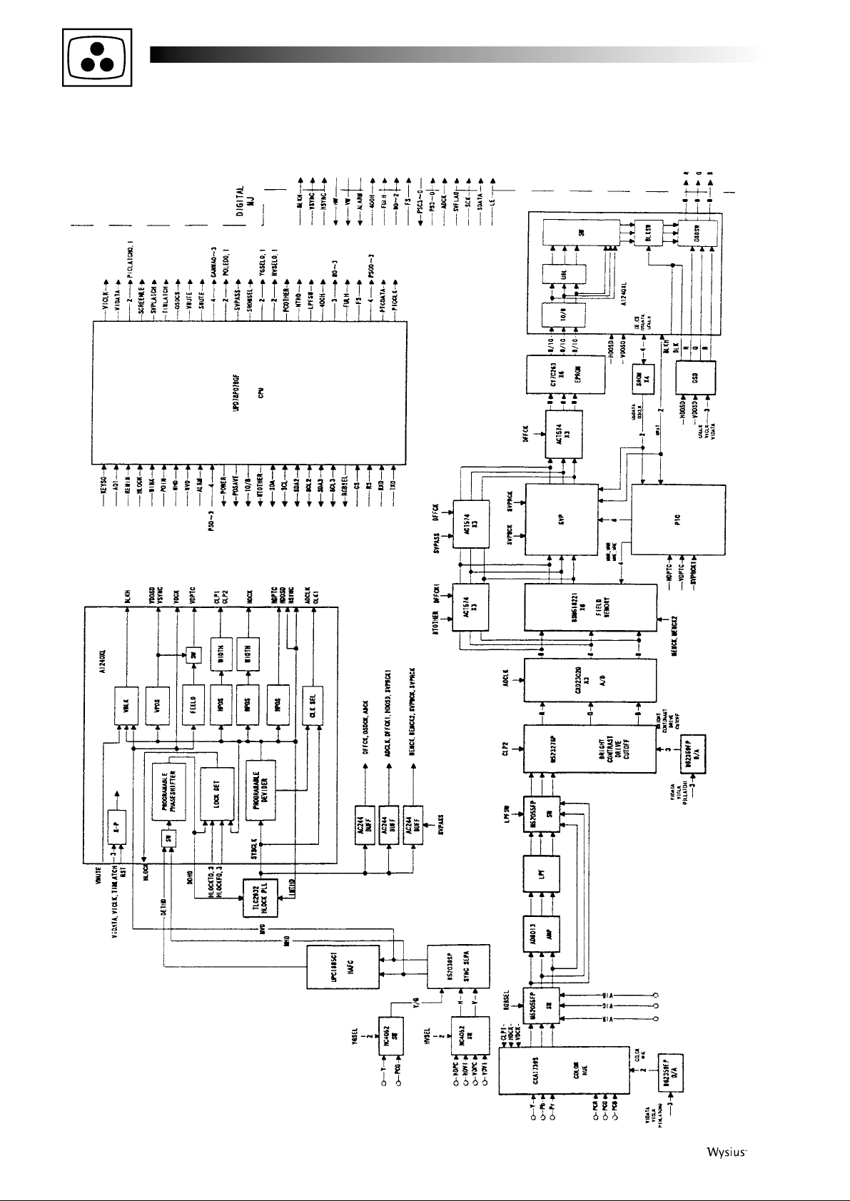
30 First issue 03 /01
ANALOG module
42WS90E
Page 31

First issue 03 / 01 31
ANALOG module
42WS90E2
Page 32

32 First issue 03 /01
VIDEO module
42WS90E - 42WS90E2
Page 33

First issue 03 / 01 33
AUDIO module
42WS90E - 42WS90E2
Page 34

34 First issue 03 /01
POWER module
42WS90E - 42WS90E2
Page 35

First issue 03 / 01 35
NOTES :
-----------------------------------------------------------------------------------------------------------------------------------------------------------------------
-----------------------------------------------------------------------------------------------------------------------------------------------------------------------
-----------------------------------------------------------------------------------------------------------------------------------------------------------------------
-----------------------------------------------------------------------------------------------------------------------------------------------------------------------
-----------------------------------------------------------------------------------------------------------------------------------------------------------------------
-----------------------------------------------------------------------------------------------------------------------------------------------------------------------
-----------------------------------------------------------------------------------------------------------------------------------------------------------------------
-----------------------------------------------------------------------------------------------------------------------------------------------------------------------
-----------------------------------------------------------------------------------------------------------------------------------------------------------------------
-----------------------------------------------------------------------------------------------------------------------------------------------------------------------
-----------------------------------------------------------------------------------------------------------------------------------------------------------------------
-----------------------------------------------------------------------------------------------------------------------------------------------------------------------
-----------------------------------------------------------------------------------------------------------------------------------------------------------------------
-----------------------------------------------------------------------------------------------------------------------------------------------------------------------
-----------------------------------------------------------------------------------------------------------------------------------------------------------------------
-----------------------------------------------------------------------------------------------------------------------------------------------------------------------
-----------------------------------------------------------------------------------------------------------------------------------------------------------------------
-----------------------------------------------------------------------------------------------------------------------------------------------------------------------
-----------------------------------------------------------------------------------------------------------------------------------------------------------------------
-----------------------------------------------------------------------------------------------------------------------------------------------------------------------
-----------------------------------------------------------------------------------------------------------------------------------------------------------------------
-----------------------------------------------------------------------------------------------------------------------------------------------------------------------
-----------------------------------------------------------------------------------------------------------------------------------------------------------------------
-----------------------------------------------------------------------------------------------------------------------------------------------------------------------
-----------------------------------------------------------------------------------------------------------------------------------------------------------------------
-----------------------------------------------------------------------------------------------------------------------------------------------------------------------
-----------------------------------------------------------------------------------------------------------------------------------------------------------------------
-----------------------------------------------------------------------------------------------------------------------------------------------------------------------
-----------------------------------------------------------------------------------------------------------------------------------------------------------------------
-----------------------------------------------------------------------------------------------------------------------------------------------------------------------
-----------------------------------------------------------------------------------------------------------------------------------------------------------------------
-----------------------------------------------------------------------------------------------------------------------------------------------------------------------
-----------------------------------------------------------------------------------------------------------------------------------------------------------------------
-----------------------------------------------------------------------------------------------------------------------------------------------------------------------
Page 36

The description and characteristics given here are of informative significance only, and non committal. To keep up the high quality of our products, we reserve the right to
make any changes or improvement without previous notice. • Les descriptions et caractéristiques figurant sur ce document sont données à titre d'information et non
d'engagement. En effet, soucieux de la qualité de nos produits, nous nous réservons le droit d'effectuer, sans préavis, toute modification ou amélioration. • Die
Beschreibungen und Daten in dieser Anleitung dienen nur zur Information und sind nicht bindend. Um die Qualität unserer Produkte ständig zu verbessern, behalten wir uns
das Recht auf Änderungen vor. • Le descrizioni e le caratteristiche date su questo documento sono fornite a semplice titolo informativo e senza impegno. Ci riserviamo il
diritto di eseguire, senza preavviso, qualsiasi modifica o miglioramento. • Las descripciones y características que figuran en este documento se dan a título de información y
no de compromiso. En efecto, en bien de la calidad de nuestros productos, nos reservamos el derecho de efectuar, sin previo aviso, cualquier modificación o mejora.
THOMSON multimedia Sales Europe - S.A. au capital de 30 000 000 - Siège : 46, quai Alphonse Le Gallo 92100 Boulogne France - RCS Nanterre B 322 019 464
THOMSON multimedia
Sales France
46, quai Alphonse Le Gallo
92648 Boulogne cedex
Tel. : 01 41 86 60 00
Minitel : 3616 ou 3623 TCEDS
Internet : http://www.thomson.fr
THOMSON multimedia
Sales UK Limited
30 T ower Vie w
Kings Hill, West Malling
Kent ME19 4NQ (England)
Tel. : 44 (0) 173 252 0920
THOMSON multimedia
Sales Italy S.p.A.
Via Leonardo da Vinci,43
20090 Trezzano sul naviglio (Milano)
Tel. : (02) 48 414 111
THOMSON multimedia
Scandinavia AB
Florettgatan 29 C
S-25467 Helsingborg (Sweden)
Tel. : 042 25 75 00
THOMSON multimedia
Switzerland
Seewenweg 5
CH-4153 Reinach
Tel. : (61) 716 96 60
THOMSON
Consumer Electronics Poland
ul.Gen.L. Okulickiego 7/9
05-500 Piaseczno (Varsovie)
Tel. : (22) 757 10 80
THOMSON multimedia
Hungary KFT
Lajos u. 78. II.em.
H-1036 Budapest
Tel. : 00 36 14 5334/80
THOMSON multimedia
Czech s.r.o.
ul. Dopravaku - dum Genius 1
Dolni Chabry
CZ - 18400 Prague 8
Tel. : (2) 688 67 70
THOMSON multimedia
Sales Germany GmbH & Co oHG
Karl-Wiechert-Allee 74
30625 Hannover
THOMSON multimedia
Sales Spain
Avenida Isla Graciosa, 1
Edificio Áncora
Parque Empresarial La Marina
28700 San Sebastián de los Reyes (Madrid)
Tel. : (91) 384 14 19
THOMSON multimedia
Sales Portugal
Avenida da Boavista, 3521
4106 Porto
Tel. : (2) 26 18 76 41
This technical documentation is for use by maintenance technicians only
Documentation technique exclusivement destinée aux professionnels de la maintenance
Diese Angaben und Hinweise sind ausschließlich für den Service des Fachhändlers bestimmt
Documentazione tecnica destinata esclusivamente ai tecnici dell'assistenza
Documentación técnica destinada exclusivamente a los profesionales de mantenimiento
 Loading...