

Page 1
IMPORTANT SAFETY INSTRUCTIONS
WARNING: To reduce the risk of electric shock, do no remove the front or back covers.
No user-serviceable parts inside. Refer servicing to qualified service personnel only.
WARNINGS & PRECAUTIONS
! To prevent damage which may result in fire or shock hazard, do not expose this product to rain or
moisture.
! To prevent electric shock, do not remove cover. No user serviceable parts are inside. Refer servicing to
qualified service personnel only.
! Keep monitor away from excessive dust, high temperatures, moisture or direct sunlight.
! Use in a well-ventilated area and do not cover ventilation openings.
! Unauthorized modification of this equipment or usage of an unshielded connecting cable may cause
excessive interference.
! When the monitor is not in use for a long period of time, disconnect it from the electric outlet.
! If the picture displayed is in any way abnormal, turn off the unit and disconnect it from the electric outlet.
Check your signal wire connections and reconnect the monitor to the electric outlet.
! Switch the monitor off using the ON/OFF button, on the rear panel, and disconnect it from the electric
outlet before cleaning. Do not use liquid or aerosol cleaners. Use only a slightly damp cloth for cleaning.
! Do not place this product on an unstable cart, stand or table. The product may fall, causing serious
damage.
! Do not place the unit on a bed, sofa, rug, or other similar surfaces. Never place the unit near or over a
radiator or heat source. Do not install unit in an enclosed area unless proper ventilation is provided.
! The unit should be operated from the type of power source indicated on the label. If the type of available
power is unknown, consult your dealer or local power company.
! The unit is equipped with a 3-pin grounded plug. The plug will only fit into a grounded power outlet. This is
a safety feature. If you are unable to insert the plug into the outlet, contact your electrician. Do not alter
the plug; this will defeat the safety feature.
! Do not rest objects on the power cord and avoid placing power cord near high traffic areas.
! Do not overload wall outlets and extension cords as this can result in a risk of fire or electric shock.
! Switch the monitor off using the ON/OFF button, on the rear panel, disconnect it from the main supply and
refer servicing to qualified service personnel under the following conditions:
The lightning flash with arrow-head
within a triangle is intended to inform
the user that parts inside the product
are a risk of electric shock.
WARNING
RISK OF ELECTRIC SHOCK
DO NOT OPEN
The exclamation point within a triangle
is intended to inform the user that
important operating and servicing
instructions are explained.
• Power cord or plug is damaged or frayed.
• Liquid has been spilled into the product.
• Unit has been exposed to water or moisture.
• Unit does not operate normally when the operating instructions are followed. Adjust only those controls
that are covered by the operating instructions, improper adjustment of other controls may result in
damage which often requires extensive work by a qualified technician to restore the unit to normal
operation.
• Unit has been dropped or the cabinet has been damaged.
• Unit exhibits a distinct change in performance, indicating a need for service.
! Use the screen saver when using a computer.
! Switch the monitor to standby mode when you do not use it.
EN
1
THOMSON is not liable if the unit is not used in accordance with this manual.
42WB03SW-EN-5-062303.p65 2003/6/23, PM 04:521
Page 2
EN
COMPLIANCE WITH CE STANDARDS
The CE label on this monitor indicates that it complies with the 89/336/EEC directive on electromagnetic
compatibility and safety rules as defined in the 73/23/EEC and 93/68/EEC low voltage directives. This unit is
protected against interferences from other electronic devices, provided that these devices comply with the
standards in force. Sporadic interferences may happen nevertheless.
2
42WB03SW-EN-5-062303.p65 2003/6/23, PM 04:522
Page 3
TABLE OF CONTENTS
IMPORTANT SAFETY INSTRUCTIONS...........................................................................................................1
COMPLIANCE WITH CE STANDARDS ...........................................................................................................2
TABLE OF CONTENTS ....................................................................................................................................2
CLEANING AND MAINTENANCE.....................................................................................................................4
PACKAGE CONTENTS ....................................................................................................................................5
UNDERSTANDING YOUR MONITOR ..............................................................................................................6
Front View ............................................................................................................................................ 6
Rear View.............................................................................................................................................6
CONNECTING THE MONITOR ........................................................................................................................7
Connecting the tuner unit .....................................................................................................................8
Connecting a PC using the RGB IN input ............................................................................................. 9
Connecting a PC via the tuner unit .....................................................................................................10
USING THE MONITOR...................................................................................................................................11
Powering ON / OFF............................................................................................................................11
Selecting Signal Source .....................................................................................................................11
Adjusting Sound Volume ....................................................................................................................11
ADVANCED FUNCTIONS...............................................................................................................................12
On-Screen Display (OSD) Settings .................................................................................................... 12
Sleep Timer Settings .......................................................................................................................... 12
Sound Adjustments ............................................................................................................................13
Switching Off Built-In Speakers .......................................................................................................... 13
Signal Frequency Information Display ................................................................................................14
ADJUSTING PICTURE ...................................................................................................................................15
TROUBLESHOOTING ....................................................................................................................................16
SPECIFICATIONS ..........................................................................................................................................17
WALL MOUNT INSTALLATION (OPTIONAL) ................................................................................................22
EN
3
42WB03SW-EN-5-062303.p65 2003/6/23, PM 04:523
Page 4
EN
CLEANING AND MAINTENANCE
Cautions When Using the Plasma Display
! Do not bring your hands, face or objects close to the ventilation holes of the plasma display.
Top of plasma display is usually very hot due to the high temperature of exhaust air being
released through the ventilation holes. Burns or personal injuries may ocurr if any body
parts are brought too close. Placing any object near the top of the display could also result
in heat related damages to the object as well as the display itself.
! Be sure to disconnect all cables before moving the plasma display. Moving the display with
its cables attached may damage the cables and thus cause fire or electric shock danger.
! Disconnect the power plug from the wall outlet as a safety precaution before carrying out any type of
cleaning or maintenance procedure.
4
Front Panel Cleaning Instructions
! The front of the display has been specially treated. Wipe the surface gently using only a cleaning cloth or
a soft, lint-free cloth.
! If the surface is particularly dirty, soak a soft, lint-free cloth in a mild detergent solution. Wring the cloth to
remove excess liquid. Wipe the surface of the display to remove dirt. Then use a dry cloth of the same
type to dry.
! Do not scratch or hit the surface of the panel with fingers or hard objects of any kind.
! Do not use volatile substances such as insect sprays, solvents and thinners.
Cabinet Cleaning Instructions
! If the cabinet becomes dirty, wipe the cabinet with a soft, dry cloth.
! If the cabinet is extremely dirty, soak a lint-free cloth in a mild detergent solution. Wring the
cloth to remove as much moisture possible. Wipe the cabinet. Use another dry cloth to
wipe over until the surface is dry.
! Do not allow any water or detergent to come into contact with the surface of the display. If
water or moisture gets inside the unit, operating problems, electrical and shock hazards may result.
! Do not scratch or hit the cabinet with fingers or hard objects of any kind.
! Do not use volatile substances such as insect sprays, solvents and thinners on the cabinet.
! Do not place anything made from rubber or PVC near the cabinet for any extended periods of time.
Avoid Still Images
! Do not allow a still picture to be displayed for extended periods of time. This can cause a
permanent image to remain on the plasma display. Examples of still images include: still
computer images, still video game images, still logos or pictures, text and images displayed
in 4:3 Normal mode.
! Screen burns are not covered by the warranty.
Contents of this manual is subject to change without notice.
Trademark Credits
! VGA is a trademark of IBM Corporation.
! Macintosh is a registered trademark of Apple Computer Corporation.
! SVGA is a registered trademark of the Video Electronics Standard Association.
! All other trademarks are the properties of their respective owners.
42WB03SW-EN-5-062303.p65 2003/6/23, PM 04:524
Page 5
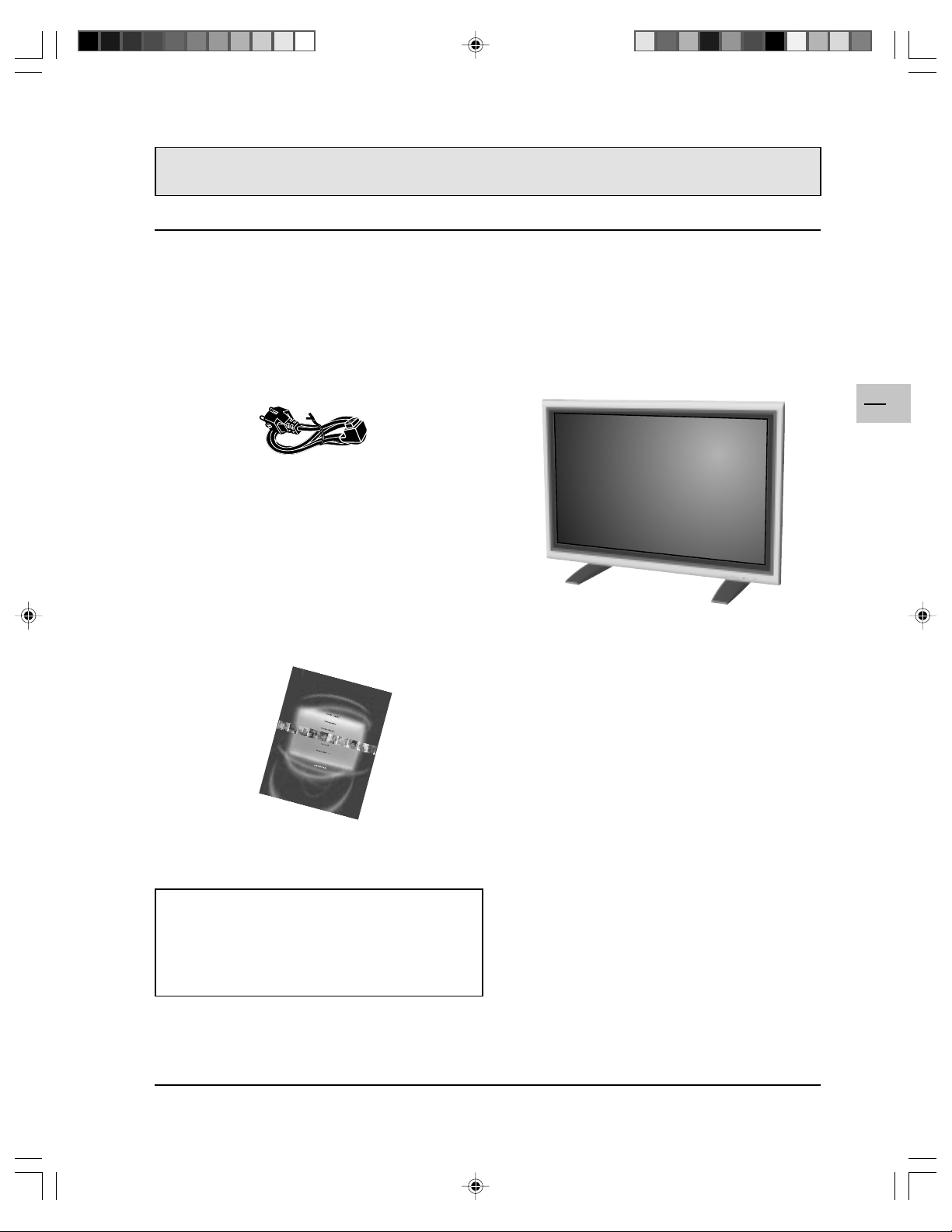
PACKAGE CONTENTS
Supplied Accessories
Please check that the monitor package contains the following items:
Power cord Plasma Monitor
EN
5
User Manual
Optional Accessories
The following accessories are available and may be
purchased from your local sales representative:
! Wall Mount (ACC 913)
! Audio Cinch Cable
42WB03SW-EN-5-062303.p65 2003/6/23, PM 04:525
Page 6
EN
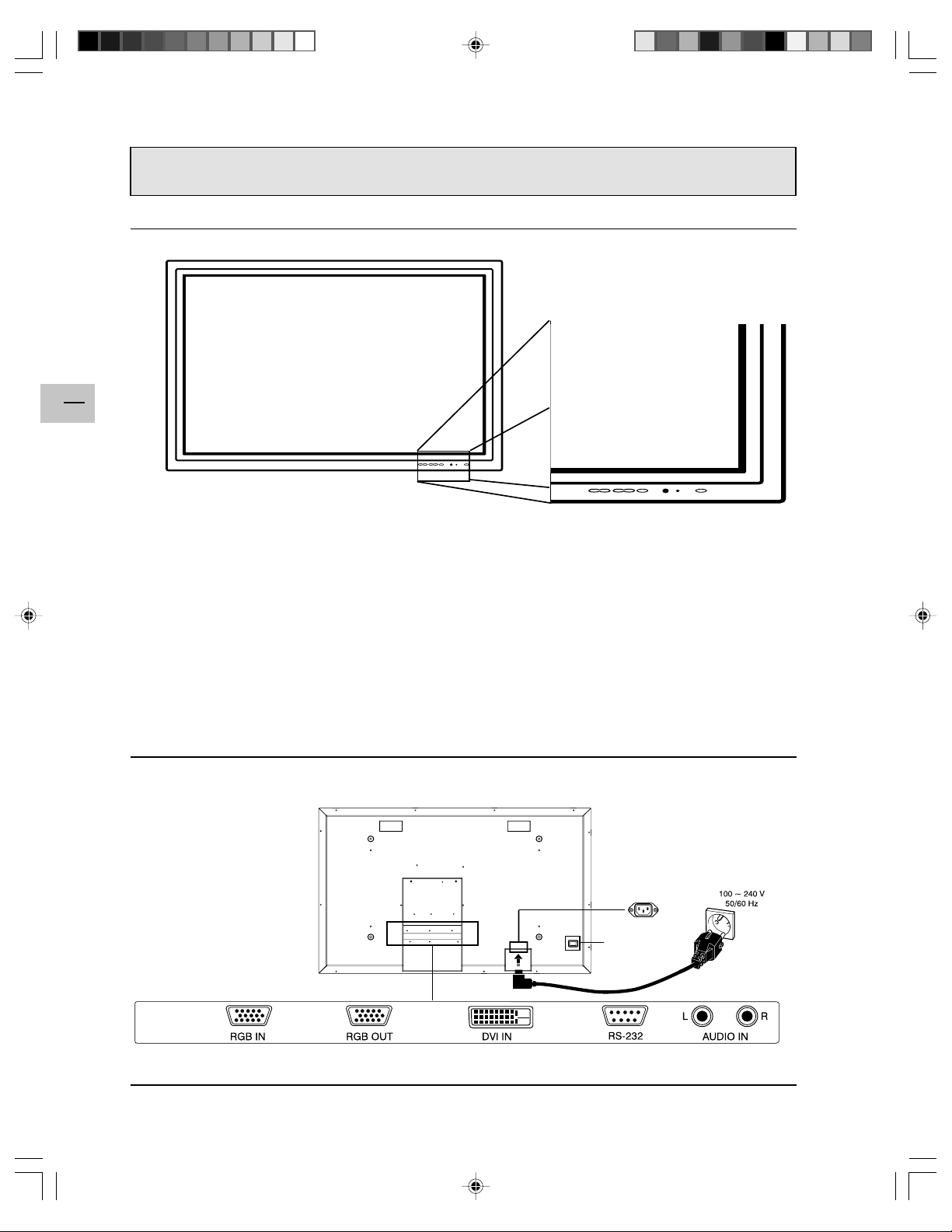
UNDERSTANDING YOUR MONITOR
Front View
6
Power (Standby) Button
Turns power on/off from standby mode. There is a 3second wait between on/off cycles.
Status LED
!!
! Off - No AC Power detected
!!
If the main power switch (rear of panel) is turned
off, this LED will not illuminate.
!!
! Yellow - Standby (Power OFF) with AC power
!!
detected
The LED will illuminate in yellow color if the
monitor is shut-off but the power cord is plugged
into the back of the unit.
!!
! Green - Power ON
!!
Rear View
Input Button
Use this button to switch between available inputs.
Menu +/- Buttons
Use these buttons to access the monitor setting
menus.
Volume Adjustment +/- Buttons
Use these buttons to adjust volume up and down.
They can also be used for adjustment in menus.
The front panel buttons are only active in RGB
mode (when you connect a PC, directly or
through the tuner unit).
Main Power
42WB03SW-EN-5-062303.p65 2003/6/23, PM 04:526
Page 7
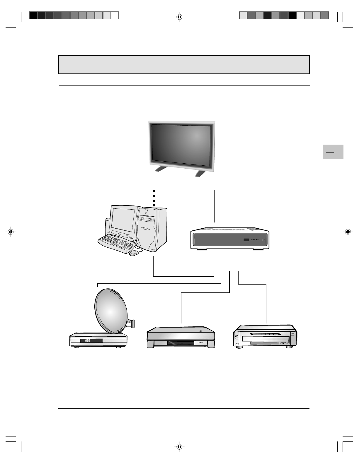
CONNECTING THE MONITOR
Your WysiusTM is a monitor: it does not generate images but allows you to view images from the various
devices connected to it. You can view TV images from the tuner unit, using the DVI socket, and you can
connect to this tuner different units such as a satellite receiver, a videorecorder, a DVD player, etc. You can
also connect a computer via the RGB sockets.
Plasma Monitor
EN
7
Computer
Satellite receiver VCR
Tuner Unit
Video CD player,
DVD player, etc.
42WB03SW-EN-5-062303.p65 2003/6/23, PM 04:527
Page 8
EN
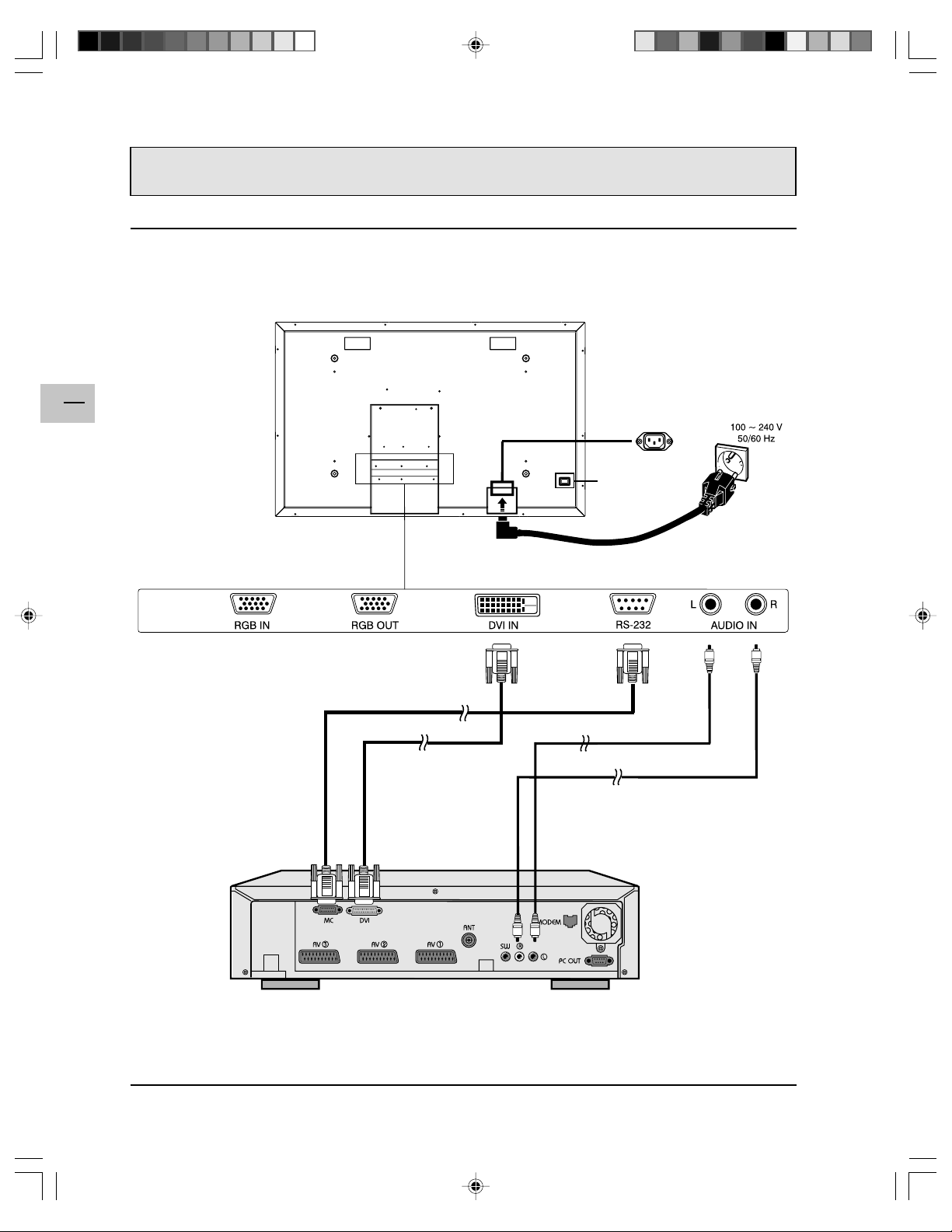
CONNECTING THE MONITOR
Connecting the tuner unit
The following diagram shows how to connect the tuner unit.
Plasma Monitor
8
Main Power
42WB03SW-EN-5-062303.p65 2003/6/23, PM 04:528
Tuner Unit
Page 9

CONNECTING THE MONITOR
Connecting a PC using the RGB IN input
You can connect a PC to your WysiusTM, directly using a VGA cable (not provided). Connect the cable to the
RGB IN socket, on the plasma monitor, and to the corresponding socket, on the computer.
Plasma Monitor
Main Power
EN
9
42WB03SW-EN-5-062303.p65 2003/6/23, PM 04:529
Computer
Page 10

EN
10
CONNECTING THE MONITOR
Connecting a PC via the tuner unit
You can connect a PC via the tuner unit. To do so, connect one end of a VGA cable (not provided) to the PC
IN socket, on the front panel of the tuner unit, and the other end to the corresponding socket on the computer.
Then connect the PC OUT socket, on the rear panel of the tuner unit, to the RGB IN socket, at the rear of the
monitor, using a VGA cable (not porvided).
Plasma Monitor
Main Power
Tuner Unit (rear view) Tuner Unit (front view)
42WB03SW-EN-5-062303.p65 2003/6/23, PM 04:5210
Computer
Page 11

Powering ON / OFF
1. Make sure the monitor is connected ot
the wall outlet and that the power switch
located at the rear of the monitor is
switched to the ON position. The Status
LED must be yellow.
2. Press the POWER button on the front
panel.
3. The monitor will now turn on after a brief
pause. The Status LED will now turn
green to indicate power on status.
4. To turn power off, press the POWER
button on the front panel.
Selecting Signal Source
Input Select
(Toggle)
USING THE MONITOR
Status LED
!!
! Off - No AC Power
!!
detected
If the main power switch
(rear of panel) is turned off,
this LED will not illuminate.
!!
! Yellow - Standby (Power
!!
OFF) with AC power
detected
The LED will illuminate in
yellow color if the monitor is
shut-off but the power cord
is plugged into the back of
the unit.
!!
! Green - Power ON
!!
1. Press the INPUT button on the front panel to select one of the
available input signal soruces.
POWER (Toggle)
EN
11
This button is only active in RGB mode (when you connect a
PC, directly or through the tuner unit).
Adjusting Sound Volume
1. Use the volume ajustment buttons on the front panel to
increase/decrease the volume.
2 Sound mute: Press the mute button on the remote control to
temporarily mute the sound. Press again to restore it.
These buttons are only active in RGB mode (when you connect
a PC, directly or through the tuner unit).
VOLUME +/-
42WB03SW-EN-5-062303.p65 2003/6/23, PM 04:5211
Page 12

EN
12
ADVANCED FUNCTIONS
On-Screen Display (OSD) Settings
Accessing OSD Settings Menu
You can set various OSD display settings.
1. Press the MENU +/- buttons on the front panel to access the main menu.
2. Use the ADJ +/- buttons to access the “OTHER” sub-menu as displayed below.
Please note that the front panel buttons are only active in RGB mode (when you connect a PC, directly or
through the tuner unit).
OSD timeout
Turns on OSD timer when set to On. When set to On, the OSD
will automatically disappear from the display if no key action is
detected for the set number of seconds. If set to Off, then OSD
will remain on the screen.
Duration
Sets the number of seconds the OSD will remain active on the
display before turning itself off. OSD timeout must be set to On.
OSD brightness
Sets the brightness level of OSD between 1 and 10.
OSD background
You can set the OSD background to transparent or blue. Set to
Off if you want a transparent background. Set to On if you want a
blue background.
Language
You can set the OSD language to English, French, Spanish,
German, or Italian.
Note:
To prevent permanent after-image, we strongly suggest setting the
“OSD timeout” feature to On.
Sleep Timer Settings
1. Press the MENU +/- buttons on the front panel to access the main
menu.
2. Use the ADJ +/- buttons to access the “OTHER” sub-menu as
displayed below.
3. Use the MENU +/- buttons to access the SLEEP function.
4. Use the ADJ +/- buttons to set to On.
5. The monitor will function normally until the 1-minute mark. At the 1minute mark, the sleep timer will display a second by second countdown clock to inform you that the monitor is about to turn off.
Please note that the front panel buttons are only active in RGB mode
(when you connect a PC, directly or through the tuner unit).
Sleep
To turn on sleep timer, switch to On position.
To turn off sleep timer, select Off.
Sleep time
You can set the timer from 1 to 120 minutes.
Use the ADJ +/- keys to set any number
between 1 and 120.
Power Off Warning
Sleep timer
0:59
42WB03SW-EN-5-062303.p65 2003/6/23, PM 04:5212
Page 13

ADVANCED FUNCTIONS
Sound Adjustments
Sound adjustments are available to enhance the sound performance of the monitor. To access sound
adjustments:
1. Press the MENU +/- buttons on the front panel to access the main menu.
2. Use the ADJ +/- buttons to access the “SOUND” sub-menu.
3. Use the MENU +/- buttons to select the various options described in this section.
Please note that the front panel buttons are only active in RGB mode (when you connect a PC, directly or
through the tuner unit).
Bass
Adjusts the bass level of the sound. For more bass response,
increase the bass level.
Treble
Adjusts the treble level of the sound. For more vocal and high
frequency response, increase the treble level.
Balance
Adjusts the balance level between LEFT and RIGHT channels. A
value of 50 is the center point between LEFT and RIGHT. To shift
the sound towards the RIGHT, increase the value up to 100. To shift
the sound towards the LEFT, reduce the value down to 1.
EN
13
Switching Off Built-In Speakers
This monitor is equipped with built-in speakers. You can switch the internal speakers on or off using the
OSD.
Internal speaker
Set to On to turn on the monitor’s internal speakers. Set to Off to
turn off internal speakers.
Note:
The built-in speakers are for factory tests only. Therefore, to use your monitor as part of a TV or Home
Cinema system, we recommend to use external speakers instead.
42WB03SW-EN-5-062303.p65 2003/6/23, PM 04:5213
Page 14

ADVANCED FUNCTIONS
Signal Frequency Information Display
Displaying Frequency of Signal
This monitor is capable of displaying the frequency level of the signal being displayed. To see signal frequency information:
1. Press the MENU +/- buttons on the front panel to access the main menu.
2. Use the ADJ +/- buttons to access the “OTHER” sub-menu.
Please note that the front panel buttons are only active in RGB mode (when you connect a PC, directly or
through the tuner unit).
EN
14
RGB
M: 05
Notes:
! When using RGB mode, the OSD will
display a mode number that references the
table above.
! Modes 15, 16, 20, 21 under RGB mode is
not available when using with DVI input.
! Modes 24-26 are for use with Apple
Macintosh computers.
H-Freq. [kHz]
Displays the horizontal signal frequency of the signal currently
displayed. Please use the frequency cross reference tables below to
see which type of signal is being displayed under various input
modes.
V-Freq. [Hz]
Displays the vertical signal frequency of the signal currently
displayed. Please use the frequency cross reference tables below to
see which type of signal is being displayed under various input
modes.
For RGB & DVI Inputs
ModeHorizontal Vertical Format Refresh
1 31.5 59.9 640×480 (VGA) 60
2 37.9 72.8 640×480 (VGA) 72
3 37.5 75.0 640×480 (VGA) 75
4 43.3 85.0 640×480 (VGA) 85
5 35.1 56.3 800x600 (SVGA) 56
6 37.9 60.3 800x600 (SVGA) 60
7 48.1 72.2 800x600 (SVGA) 72
8 46.9 75.0 800x600 (SVGA) 75
9 53.7 85.0 800x600 (SVGA) 85
10 48.4 60.0 1024x768 (XGA) 60
11 56.5 70.0 1024x768 (XGA) 70
12 60.0 75.0 1024x768 (XGA) 75
13 68.7 85.0 1024x768 (XGA) 85
14 64.0 60.0 1280x1024 (SXGA) 60
15* 80.0 75.0 1280x1024 (SXGA) 75
16* 91.1 85.0 1280x1024 (SXGA) 85
18 31.5 70.0 720x400 (DOS) 70
19 31.5 50.0 640x480 (VGA) 50
20* 45.2 60.0 1280x720P (HDTV) 60
21* 33.8 60i 1920x1080i (HDTV) 60
22 31.5 70.0 640x350 (VGA) 70
23 31.7 60.4 852x480 (WVGA) 60
24 35.0 66.7 640x480 (Apple) 67
25 49.7 74.6 832x624 (Apple) 75
26 68.7 75.0 1152x870 (Apple) 75
42WB03SW-EN-5-062303.p65 2003/6/23, PM 04:5214
Page 15

ADJUSTING PICTURE
Accessing Picture Adjustment Mode
Various picture adjustments can be set using the PICTURE menu. To access this menu:
1. Press the MENU +/- buttons on the front panel to
access the main menu.
2. The first menu displayed is the PICTURE menu.
Make sure that the PICTURE menu is displayed.
3. Use the MENU +/- buttons to select the option you
wish to adjust. An explanation of each adjustment is
listed below.
4. Use the ADJ +/- buttons to change the setting.
Please note that the front panel buttons are only active in RGB mode (when you connect a PC, directly or
through the tuner unit).
Contrast
Adjust Contrast to increase the level of “white” in the video picture.
Increasing contrast will make white areas of the video picture brighter.
Contrast works in conjuction with Brightness.
Brightness
Adjust brightness to enhance the level of dark areas in the video picture
such as night scenes and shadow scenes. Increasing brightness will make
dark areas more visible.
Color temperature
Select the color temperature for white balance. There are three settings to
choose from: (1) Low - sets to 7180K; (2) Mid - sets to 8680K; (3) High sets to 10180K
EN
15
Phase
Use phase to fine-tune the monitor to perfectly synchronize the video’s
signal source.
Format
Use to change the image format. There are two selections available: 16:9
and 4:3.
V-height
Use to change vertical size of the picture. Increase to enlarge the picture
size in the vertical direction. Decrease to reduce the picture size in the
vertical direction.
V-position
Use to change vertical position of the picture. Increase to shift the picture
up. Decrease to shift the picture down.
H-Width
Use to change horizontal size of the picture. Increase to enlarge the
picture size in the horizontal direction. Decrease to reduce the picture size
in the horizontal direction.
H-position
Use to change horizontal position of the picture. Increase to shift the
picture to the right. Decrease to shift the picturn to the left.
Notes:
1. Each of the (3) color temperature settings may not be exactly equal to the temperature setting as
defined; however, it will be approximately close.
42WB03SW-EN-5-062303.p65 2003/6/23, PM 04:5215
Page 16

TROUBLESHOOTING
Troubleshoot Common Conditions
The following table lists some problems that you may encounter and methods for remedy. Please refer to
this table before contacting a service representative.
EN
16
Symptom
No picture is displayed. 1. The power cord is disconnected.
Interference displayed on
the monitor or noise is
heard.
Color is abnormal.
Picture is distorted with
abnormal patterns.
Display image doesn’t fill up
the full size of the screen.
Can hear sound, but no
picture.
Can see picture but no
sound is heard.
Some picture elements do
not light up.
After-Images can still be
seen on the monitor after the
monitor is powered off.
(Examples of still pictures
include logos, video games,
computer images, and
images displayed in 4:3
normal mode).
Possible Cause Remedy
2. The main power switch on the back of the
monitor is not switched on.
3. The selected input has no connection.
4. The monitor is in standby mode in RGB
mode.
1. Caused by surrounding electrical
appliances, cars/motorcycles or fluores-
cent lights.
1. The signal cable is not connected properly.
1. The signal cable is not connected properly.
2. The input signal is beyond the capabilities
of the monitor.
1. If under RGB mode, the H-Size and V-Size
is incorrectly set.
2. If under TV, AV1, AV2, or Component with
480i input, the 4:3 WIDE mode is switched
on.
1. Improperly connected source signal cable. 1. Make sure that both video and sound
1. Improperly connected source signal cable.
2. Volume is turned all the way down.
3. MUTE is turned on.
1. Some pixels of the plasma display may not
turn on.
1. A still picture is displayed for an over
extended period of time.
1. Plug in the power cord.
2. Make sure the power switch is switched
on.
3. Connect a signal connection to the
monitor.
4. Press any key on your keyboard.
1. Move the monitor to another location to
see if the interference is reduced.
1. Make sure that the signal cable is firmly
attached to the back of the monitor.
1. Make sure that the signal cable is firmly
attached.
2. Check the video signal source to see if
it is beyond the range of the monitor.
Please check its specifications with this
monitor’s specification section.
1. Use H-Size and V-Size to adjust the
size of the video.
2. Use the WIDE key to scroll through
various full screen modes.
inputs are correctly connected.
1. Make sure that both video and sound
inputs are correctly connected.
2. Use the volume buttons to turn the
volume up.
3. Switch MUTE off by pressing the MUTE
button on the remote control.
1. This monitor is manufactured using an
extremely high level of precision
technology; however, sometimes some
pixels of the monitor may not display.
This is not a malfuction. Please see the
enclosed warranty card for more
information.
1. Do not allow a still image to be
displayed for an extended period of time
as this can cause a permanent afterimage to remain on the monitor.
42WB03SW-EN-5-062303.p65 2003/6/23, PM 04:5216
Page 17

Display Panel
Screen size 42 inches
Aspect ratio 16:9 wide
Number of pixels 852 X 480 pixels
Pixel Pitch 1.08mm X 1.08mm
Luminosity 1000 cd/m
2
(without filter)
Power Source
Input voltage 100 ~ 240 Vac , 50 / 60 Hz
Input current 3.3A
Inrush current 60 A p-p/20ms Max.
Power consumption 380±10% Watts
Stand-by & Power Save 5 Watts Max.
Connection
Connector Types Audio cinch sockets
9 pin D-SUB for RS232
15 pin D-SUB for RGB
24 pin DVI
RGB Signal
Type TTL
Polarity Positive or Negative
Amplitude RGB: 0.7Vp-p
Frequency H: support to 31~91 kHz
V: support to 50~85 Hz
SPECIFICATIONS
EN
17
DVI Signal
Type Digital
Polarity Positive or Negative
Frequency H: support to 31~63 kHz
V: support to 50~85 Hz
Audio Signal Analog 500mV rms /more than 22 kohm
Pin Assignments For D-SUB Connector (In / Loop Out)
Pin Signal Assignment Pin Signal Assignment Pin Signal Assignment
1 RED 6 RED GND 11 GND
2 GREEN 7 GREEN GND 12 SDA
3 BLUE 8 BLUE GND 13 H-SYNC
4 GND 9 NC 14 V-SYNC
5 GND 10 GND 15 SCL
42WB03SW-EN-5-062303.p65 2003/6/23, PM 04:5217
Page 18

EN
18
SPECIFICATIONS
Pin Assignments For 24 Pin DVI Connector(Digital Only)
Pin Signal Assignment Pin Signal Assignment Pin Signal Assignment
1 TMDS Data 2- 9 TMDS Data 1- 17 TMDS Data 02 TMDS Data 2+ 10 TMDS Data 1+ 18 TMDS Data 0+
3 TMDS Data 2/4 Shield 11 TMDS Data 1/3 Shield 19 TMDS Data 0/5 Shield
4 TMDS Data 4- 12 TMDS Data 3- 20 TMDS Data 55 TMDS Data 4+ 13 TMDS Data 3+ 21 TMDS Data 5+
6 DDC Clock 14 +5V Power 22 TMDS Clock Shield
7 DDC Data 15 Ground (For +5V) 23 TMDS Clock +
8 No Connect 16 Hot Plug Detect 24 TMDS Clock -
RGB/DVI For VESA Standard
Refresh Horizontal Vertical V-Sync H-Sync
Mode Rate Frequency Frequency Polariy Polarity Dot rate
No. Resolution (Hz) (kHz) (Hz) (TTL) (TTL) (MHz)
1 640(VGA)×480 60 31.5 59.94 - - 25.175
2 640(VGA)×480 72 37.9 72.81 - - 31.500
3 640(VGA)×480 75 37.5 75 - - 31.500
4 640(VGA)×480 85 43.3 85.01 - - 36.000
5 800(SVGA)×600 56 35.1 56.25 + + 36.000
6 800(SVGA)×600 60 37.9 60.317 + + 40.000
7 800(SVGA)×600 72 48.1 72.19 + + 50.000
8 800(SVGA)×600 75 46.9 75 + + 49.500
9 800(SVGA)×600 85 53.7 85.06 + + 56.250
10 1024(XGA)×768 60 48.4 60.01 - - 65.000
11 1024(XGA)×768 70 56.5 70.07 - - 75.000
12 1024(XGA)×768 75 60.0 75.03 + + 78.750
13 1024(XGA)×768 85 68.7 84.99 + + 94.500
14 1280(SXGA)×1024 60 63.98 60.02 + + 108.00
15* 1280(SXGA)×1024 75 79.98 75.03 + + 135.00
16* 1280(SXGA)×1024 85 91.15 85.02 + + 157.50
18 720(DOS)×400 70 31.46 70.08 + - 28.320
19 640(VGA)×480 50 31.5 50 - - 25.175
20* 1280(HDTV)×720P 60 45.15 60 - - 74.250
21* 1920(HDTV)×1080I 60(I) 33.75 60 - - 74.250
22 640(VGA)×350 70 31.50 70 - + 25.175
23 852(WGA)×480 60 31.72 60.41 - - 30.00
* These modes are not supported in DVI mode.
RGB/DVI For Apple Standard
Mode Rate Resolution Resolution Polarity Polarity Dot rate
No. Resolution (Hz) (kHz) (Hz) (TTL) (TTL) (MHz)
24 640 × 480 67 35.00 66.67 - - 30.240
25 832 x 624 75 49.73 74.55 - - 57.283
26 1152 x 870 75 68.68 75.06 - - 100.000
Maximum Resolution Up to 1280 x 1024
42WB03SW-EN-5-062303.p65 2003/6/23, PM 04:5218
Refresh Horizontal Vertical V-Sync H-Sync
Page 19

Dimensions Without Stand With Stand
Width 1040 mm 1040 mm
Height 648 mm 690 mm
Depth 95 mm 287.5 mm
Package Dimensions
Width 1230 mm
Height 960 mm
Depth 470 mm
Weight
Net weight 31.2 kg (without stand) / 35 kg (with stand)
Gross weight 46 kg
SPECIFICATIONS
EN
19
Operating
Temperature 0~40
o
C
Relative humidity 20~80%
Pressure 800~1114hpa
Non-Operating
Temperature -20~60
o
C
Relative humidity 20~90%
Pressure 600~1114hpa
Vibration X/Y/Z, 0.5G/10~55Hz(sweep), 10 minutes
Acoustics
(IHF A-weighted 1meter) 40dB Max.
Sound
Residual hum (at volume max) 500µW Max.
Practical max. Audio output (at 10% THD max.) 1.0vp-p 1 kHz input 5W +5W Max. /12 ohm
Sound distortion (at 250 mw 1 kHz) 1% Max.
Audio output (input at 1.4V
Reliability Requirement
The MTBF is 20000hrs under operation 25±5
) >=1.0 V
P-P
o
C (Half luminosity, motion picture)
P-P
Power Management
Mode H-sync V-sync Video Power dissipation
Normal Pulse Pulse Active Normal power
Stand-by No pulse No pulse No video Power off
Power saving Pulse No pulse blanked Less than 5 watts
No pulse Pulse
This Plasma display is Energy star compliant when used with a computer equipped with DPMS.
42WB03SW-EN-5-062303.p65 2003/6/23, PM 04:5219
Page 20

EN
20
SPECIFICATIONS
Preset Timing Chart
Item Description:
A Total time
B Active display area including borders
C Active display area excluding borders
D Left/Top border
E Right/bottom border
F Blanking time
G Front porch
H Sync-width
I Back porch
Mode No 1 2 3 4 5 6 7 8 9
H Resolution 640 640 640 640 800 800 800 800 800
V Resolution 480 480 480 480 600 600 600 600 600
Refresh Rate 60 72 75 85 56 60 72 75 85 Hz
Pixel 25.175 31.5 31.5 36 36 40 50 49.5 56.25 MHz
Horizontal visible 640 640 640 640 800 800 800 800 800 Dots
Horizontal total 800 832 840 832 1024 1056 1040 1056 1048 Dots
Horizontal front porch 1 6 24 16 56 24 40 56 16 32 Dots
Horizontal sync 96 40 64 56 72 128 120 80 64 Dots
Horizontal back porch 48 128 120 80 128 88 64 160 152 Dots
Horiz blanking time 160 192 200 192 224 256 240 256 248 Dots
Vertical visible 480 480 480 480 600 600 600 600 600 Lines
Vertical total 525 520 500 509 625 628 666 625 631 Lines
Vertical front porch 10 9 1 1 1 1 37 1 1 Lines
Vertical sync 2 3 3 3 2 4 6 3 3 Lines
Vertical back porch 33 28 16 25 22 23 23 21 27 Lines
Vertical blanking time 45 40 20 29 25 28 66 25 31 Lines
Horizontal frequency 31.469 37.9 37.5 43.3 35.1 37.9 48.1 46.9 53.7 kHz
Vertical frequency 59.94 72.81 75 85.01 56.25 60.317 72.19 75 85.06 Hz
Vertical sync polarity - - - - + + + + + TTL
Horiz sync polarity - - - - + + + + + TTL
Dot rate 25.175 31.5 31.5 36 36 40 50 49.5 56.25 MHz
42WB03SW-EN-5-062303.p65 2003/6/23, PM 04:5220
Page 21

SPECIFICATIONS
Mode No 10 11 12 13 14 15 16 18 19
H Resolution 1024 1024 1024 1024 1280 1280 1280 720 640
V Resolution 768 768 768 768 1024 1024 1024 400 480
Refresh Rate 60 70 75 85 60 75 85 70 50 Hz
Pixel 65 75 78.75 94.5 108 135 157.5 28.320 25.175 MHz
Horizontal visible 1024 1024 1024 1024 1280 1280 1280 720 640 Dots
Horizontal total 1344 1328 1312 1376 1688 1688 1728 900 800 Dots
Horizontal front porch 24 24 16 48 48 16 64 18 16 Dots
Horizontal sync 136 136 96 96 112 144 160 108 96 Dots
Horizontal back porch 160 144 176 208 248 248 224 54 48 Dots
Horiz blanking time 320 304 288 352 408 408 448 180 160 Dots
Vertical visible 768 768 768 768 1024 1024 1024 400 480 Lines
Vertical total 806 806 800 808 1066 1066 1072 449 629 Lines
Vertical front porch 3 3 1 1 1 1 1 12 62 Lines
Vertical sync 6 6 3 3 3 3 3 2 2 Lines
Vertical back porch 29 29 28 36 38 38 44 35 85 Lines
Vertical blanking time 38 38 32 40 42 42 48 49 149 Lines
Horizontal frequency 48.4 56.5 60 68.7 63.98 79.98 91.15 31.46 31.5 kHz
Vertical frequency 60.01 70.07 75.03 84.99 60.02 75.03 85.02 70.08 50 Hz
Vertical sync polarity - - + + + + + + - TTL
Horiz sync polarity - - + + + + + - - TTL
Dot rate 65 75 78.75 94.5 108 135 157.5 28.32 25.175 MHz
EN
21
Mode No 20 21 22 23 24 25 26
H Resolution 1280 1920 640 852 640 832 1152
V Resolution 720P 1080i 350 480 480 624 870
Refresh Rate 60 60i 70 60 67 75 75 Hz
Pixel 74.250 74.25 25.175 30 30.240 57.283 100.000 MHz
Horizontal visible 1280 1920 640 852 640 832 1152 Dots
Horizontal total 1650 2200 800 955 864 1152 1456 Dots
Horizontal front porch 70 44 16 19 64 32 32 Dots
Horizontal sync 40 44 96 48 64 64 128 Dots
Horizontal back porch 260 192 48 36 96 224 144 Dots
Horiz blanking time 370 280 160 103 224 320 304 Dots
Vertical visible 720 540 350 480 480 624 870 Lines
Vertical total 750 562.5 449 525 525 667 915 Lines
Vertical front porch 5 3 37 10 3 1 3 Lines
Vertical sync 5 2 2 2 3 3 3 Lines
Vertical back porch 20 18 60 33 39 39 39 Lines
Vertical blanking time 30 23 99 45 45 43 45 Lines
Horizontal frequency 45.00 33.75 31.50 31.413 35.00 49.73 68.68 kHz
Vertical frequency 60 60 70 59.835 66.667 74.55 75.06 Hz
Vertical sync polarity - - - - - - - TTL
Horiz sync polarity - - + - - - - TTL
Dot rate 74.25 74.25 25.175 30 30.24 57.283 100.000 MHz
42WB03SW-EN-5-062303.p65 2003/6/23, PM 04:5221
Page 22

WALL MOUNT INSTALLATION (OPTIONAL)
Package Content
An optional wall-mount is available. Please contact your local retailer for more information.
EN
22
Left Wall Angle
Module
AB
Screws for Fix Angle x 8
Right Wall Angle
Module
Screws for Wall
Mounting x 8
Horizontal Support
C
D
E
42WB03SW-EN-5-062303.p65 2003/6/23, PM 04:5222
F
Page 23

WALL MOUNT INSTALLATION (OPTIONAL)
Setup Steps
Step 1.
Attach Horizontal Supports (C and D) to the
Left and Right Wall Angle Module ( A and
B) with screws (E).
Step 2.
Install the Wall Mount Bracket onto the wall.
Note:
The screws in this package are for
mounting onto a wooden wall. Different
kind of walls (cement walls, for example)
need different type screws. Please consult
with a qualified installer to make sure your
wall is capable of supporting this bracket
and plasma monitor.
EN
23
You can adjust the mounting direction and
inclination angle (0, 5, 10, 15 degrees) by
adjusting the screws position on the Wall
Mounting Angle Module.
42WB03SW-EN-5-062303.p65 2003/6/23, PM 04:5223
Page 24

EN
24
WALL MOUNT INSTALLATION (OPTIONAL)
Step 3.
Remove the pedestal table-top stand on the unit, install the unit onto the wall mount bracket.
Note:
! Wall mount bracket is an optional accessory, please contact your local sales agent for more
information.
! This type of equipment is to be installed by qualified installers, please contact with authouized
dealer for installation.
! Please make sure that your wall is capable of supporting this wall mount and plasma monitor which
can weigh over 120 kg.
42WB03SW-EN-5-062303.p65 2003/6/23, PM 04:5224
 Loading...