

Page 1

2
RCA 25450
4-Line Wireless
Telephone System
User’s Guide
Table of Contents
Safety Instructions...............................................................4
General Safety Instructions............................................4
Product Safety Instructions............................................5
Battery Safety Instructions.............................................7
Regulatory Information.......................................................8
Welcome .............................................................................10
Equipment Checklist.........................................................11
Handset Ill ustration............................................................12
Handset Controls and Display.........................................13
Base Unit Illustration.........................................................15
Base Unit Controls and Display......................................16
Installations.........................................................................20
Summary of Features .......................................................23
Basic Operations ...............................................................29
Making a Telephone Call..............................................29
Receiving a Telephone Call .........................................30
Making an Intercom Call...............................................31
Receiving an Intercom Call..........................................32
Ending a Call..................................................................33
Making a Page from the Base Unit .............................34
Redial...............................................................................34
Adjusting Voice Volume................................................36
Adjusting Ringer Volume..............................................36
Setting Time and Date on the Base Unit...................37
Putting Cal l(s) on Hold..................................................38
Mute.................................................................................39
Do Not Disturb................................................................40
Key Guard (Handset Onl y)...........................................40
Viewing Call Log................................ ............................40
Recording AA Main Greeting Message......................42
Recording Mailbox Greeting Message .......................43
Battery Recharge and Replacement ..........................45
Advanced Operations .......................................................46
Auto Attendant (AA) ......................................................46
Call Forwarding ..............................................................49
Page 2

3
Call Transfer...................................................................50
4
Directory Operations .....................................................52
Group Subscription ........................................................54
Line Dedication..............................................................56
Line Selection.................................................................57
Menu Operations...........................................................58
Registration/Deregistration...........................................65
Reset System .................................................................69
Second Incoming Call...................................................70
Speed Dial (Base Unit).................................................71
Three-way Conferencing..............................................72
Voice Mail.......................................................................75
Technical Specifications...................................................80
Safety Instructions
Caution: Your wireless telephone gives you freedom and
flexibility to stay in touch while you move around. However, the
safe and responsible use of the phone depends entirely on you.
When using your phone equipment, safety instructions should
be followed to avoid the risks of fire, electric shock, injury to
person, and damage to property.
General Safety Instructions
1. When using your wireless phone, ensure your safety and the
safety of others:
a. Always watch where you are walking and standing.
b. Don’t let a phone call distract you from working safely.
2. In an emergency:
a. If an emergency occurs, dial the emergency phone
number. However, if you are in an area where your phone
does not have a clear signal from the base, it is highly
probable that the call may not go through. Locate the
nearest landline telephone or other communications
devices to call for help.
b. Emergency calls may not automatically provide
emergency personnel with your name, phone number or
location. Tell the operator
i) Your name and phone number
ii) The nature of the emergency
iii) Whether police, fire, or medical assistance is needed
iv) The exact location of the emergency, including
address, cross streets, mileposts or landmarks.
3. Notice to Hearing Aid Users: This phone system is compatible
with inductively coupled hearing aids.
4. Notice to Cardiac Pacemaker Users: Preliminary studies done
by the US FDA and others have shown that, although
interference to the implanted cardiac pacemaker may occur
when operating very closely, wireless telephones “do not
seem to pose a significant problem for pacemaker wearers.”
However, until more is known, FDA suggests that people with
pacemakers may want to take precautions when using or
carrying a wireless telephone to ensure that there is ample
distance between the telephone and the pacemaker. Do not
Page 3

5
carry the handset in a breast pocket. If you have any reason
6
to suspect that interference is taking place, turn off your
handset immediately.
Product Safety Instructions
1. Read and understand all instructions.
2. Follow all warnings and instructions including those marked on
the product.
3. Changes or modifications to this product not expressively
approved by the manufacturer will void the warranty and the
FCC authorization to operate the equipment. Use only
manufacturer provided accessories.
4. Do not use the telephone near water. Never spill liquid of any
kind on this product.
5. Unplug the product from the wall telephone jack and power
outlet before cleaning. Do not use liquid or aerosol cleaners.
Use damp cloth for cleaning.
6. Do not place this product on an unstable cart, stand or table.
The product may fall and cause personal injury or damage to
the product or other property. Place the Base Unit and the
charger on hard, flat surfaces.
7. Power Outage:
In the event of a power outage, your handset charger will not
recharge the handset battery. The Base Unit’s backup battery
can provide connection although its capacity is limited.
Therefore, you should have a telephone that does not require
electricity available for use during power outage, or have a
high-capacity backup power supply.
8. Slots or openings in the product’s housing are provided for
ventilation. These openings must not be blocked or covered.
Placing the product on a bed, carpeting, or ot her similar
surface may block these openings and should be avoided.
This product should never be placed near or over a radiator or
heat register, or in a built-in installation unless proper
ventilation is provided.
9. Never push objects of any kind into this product through
housing slots/openings as they may damage the product,
touch dangerous voltage points or short out parts that could
result in fire, electric shock, or injury.
10. This product should be operated only from the type of power
source indicated on the marking label. If you are not sure of
the type of power supply to your home, consult your dealer or
local power company.
11. Do not overload wall power outlets and extension cords as this
may result in fire or electric shock.
12. To avoid electric shock or burn, do not disassemble this
product. Send this product to an authorized service center
when service or repair work is required. Call Customer
Service for locations near you. Opening or removing covers
will void the product warranty and may expose you to
dangerous voltages, electrical currents or other risks.
Incorrect reassembling of the product may cause electric
shock when the product is subsequently used.
13. Avoid using the product during a storm. There may be a risk
of electric shock from lightning.
14. Do not place the product where persons can step, trip, or fall
on the product.
15. Do not place conductive objects over or near the antenna.
16. Do not use the product to report a gas leak while in the vicinity
of the leak.
17. Do not install the Base Unit or the handset charger near
microwave ovens, radios, TV sets, speakers, or other
electrical equipment. These appliances may cause
interference to the product or experience interference from the
product.
18. Unplug the Base Unit or the charger adaptor from the wall
power outlet and refer servicing to an authorized service
center under the following conditions:
a. If liquid had been spilled into the product.
b. When the power supply cord or plug is damaged or frayed.
c. If the product has been exposed to rain or water.
Page 4

7
d. If the product does not operate normally by following the
8
operating instructions.
e. If the product has been dropped or housing has been
damaged.
f. If the product shows a distinct change in performance.
Battery Safety Instructions
1. Use only manufacturer approved rechargeable batteries and
charger. Do not use other types of rechargeable batteries or
non-rechargeable batteries. The batteries could short-circuit,
and the battery enclosure may be damaged causing a
hazardous condition.
2. Follow the charging instruction in this manual and instruction
labels and markings in the handset and charger compartments.
3. Battery must be recycled or disposed of properly. Do not
dispose the battery in a fire. The cells may explode.
4. Do not dispose of the battery in municipal was te. Check with
local codes for disposal instructions.
5. Exercise care in handling the batteries in order not to shortcircuit the battery with conductive materials such as rings,
bracelets, keys, pocketknife, and coins. The battery or
conductive material may overheat and cause burn or fire.
6. Do not expose batteries to rain or water.
7. Do not open or mutilate the battery. Released electrolyte is
corrosive and may cause injury to eyes or skin. The
electrolyte may be toxic if swallowed.
8. During charging, the battery heats up. This is normal and is
not dangerous.
Regulatory Information
Model: 25450XXX -A
FCC ID: G9H2-5450A
This device complies with Part 15 of the FCC Rules. Operation
is subject to the following two conditions:
1) this device may not cause harmful interference, and
2) this device must accept any interference received, including
interference that may cause undesired operation.
Privacy of communications may not be ensured when using this
phone.
1. This telephone system complies with rules of the FCC Part 68.
On the bottom of the Base Unit is a label that contains, among
other information, the FCC Registration Number, Ringer
Equivalence Number (REN) and the Universal Service Order
Code, which is RJ-11C in the U.S. Your telephone company
may ask you for this information.
2. The REN is useful to determine the quantity of devices you
may connect to your telephone line and still have all devices
ring when your telephone number is called. In most, but not
all, areas the sum of the REN’s of all devices connected to
one line should not exceed 5.0. To be certain of the number
of devices you may connect to your phone line, you should
contact you local telephone company for the maximum REN in
your area.
3. If your telephone equipment causes problems to the telephone
network, the telephone company may ask you to disconnect
your phone system from the line until the problem has been
corrected. Consult with your local phone company for your
rights if this happens.
4. Your telephone company may m ake changes in its facilities,
equipment, operations, or procedures that could affect the
proper functioning of your telephone system. Consult with
your local phone company for your rights if this happens.
5. This telephone system may not be used on coin service
provided by the telephone company. Connection to party lines
is subject to state tariffs.
Page 5

9
10
6. This telephone system has been tested and found to comply
with the limits for Class B digital devices, pursuant to Part 15
of the FCC Rules. These limits are designed to provide
reasonable protection against harmful interference in a
general public installation. Operations of these devices may
still encounter interference from/to nearby TV’s, VCR’s, radios,
computers, or other electronic devices. To minimize or
prevent such interference, the telephone system should not be
placed or operated near other electronic devices. If
interference occurs, moving the Base Unit and the handset
farther away from them will often reduce or eliminate the
interference.
7. Howev er, there is no guarantee that interference will not occur
in a particular installation. If this telephone system does
cause interference to other electronic devices, which can be
determined by turning the system off and on, the user is
encouraged to try to correct the interference by one or several
of the following measures:
a. Increase the space separation between the handset or
Base Unit and the device that is experiencing interference.
We recommend 20 feet or more between the system and
other electronic devices.
b. Connect the Base Unit to a power outlet on a circuit
separate from that used by the device experiencing
interference.
c. Consult the dealer or an experienced electronic technician
for help.
Welcome
You have purchased an exceptional communications tool from a
leading telephone system manufacturer.
The RCA 25450 4- line Telephone System is ideal for users in
various residential and business settings. With sophisticated
digital signal processing and high quality hardware designs, the
RCA 25450 provides long -range telephone connections and 2-way
handset-to-handset communications in a wide variety of
environment from around-the- house, multi-level office buildings,
factories, hotels/resorts, warehouses, retail stores, convention
facilities, farms, business complexes, construction sites, schools,
car dealerships, grocery stores, and many others.
The unique 2-way radio feature allows handsets to communicate
with each other as digital, full-duplex 2-way radios. Members of
work group(s) can be in contact with their co-workers while leaving
phone lines available for incoming and outgoing calls. Handsets
that are within range of each other can use the 2-way feature even
while out of range of the Base Unit. RCA 25450 can support up to
16 handsets and 4 groups.
Your new system is plug -and-play and is ready for making and
receiving calls. However, there are many advanced features that
you can explore through user-friendly interface. The following
sections will first describe the controls and displays on the Base
Unit and the Handset along with their meanings and basic usage.
A summary of more advanced features then follows with
references to page numbers where detail operations can be found.
Page 6
11
Equipment Checklist
12
1. In a Base + Handset package (Order Number: xxxx), please
find the following components:
a. Base Unit x 1 (Order Number: xxxx)
b. Base 7.5V AC/DC Adaptor x 1 (Order Number: xxxx)
c. Base Corded Handset x 1 (Order Number: xxxx)
d. Base Handheld Cord x 1 (Order Number: xxxx)
e. Base Backup Battery x 1 (Order Number: xxxx)
f. Handset x 1 (Order Number: xxxx)
g. Handset Battery Pack x 1 (Order Number: xxxx)
h. Charger x 1 (Order Number: xxxx)
i. Charger 5.5V AC/DC Adaptor x 1 (Order Number: xxxx)
j. Belt Clip x 1 (Order Number: xxxx)
k. 4-wire Telephone Cord x 4 (Order Number: xxxx)
l. User’s Guide, Quick Guide, and Warranty Card (Order
Number: xxxx)
2. In a Handset package (Order Number: xxxx), please find the
following components:
a. Handset x 1 (Order Number: xxxx)
b. Handset Battery Pack x 1 (Order Number: xxxx)
c. Charger x 1 (Order Number: xxxx) (Order Number: xxxx)
d. Charger 5.5V AC/DC Adaptor x 1 (Order Number: xxxx)
e. Belt Clip x 1 (Order Number: xxxx)
f. Quick Guide, and Warranty Card (Order Number: xxxx)
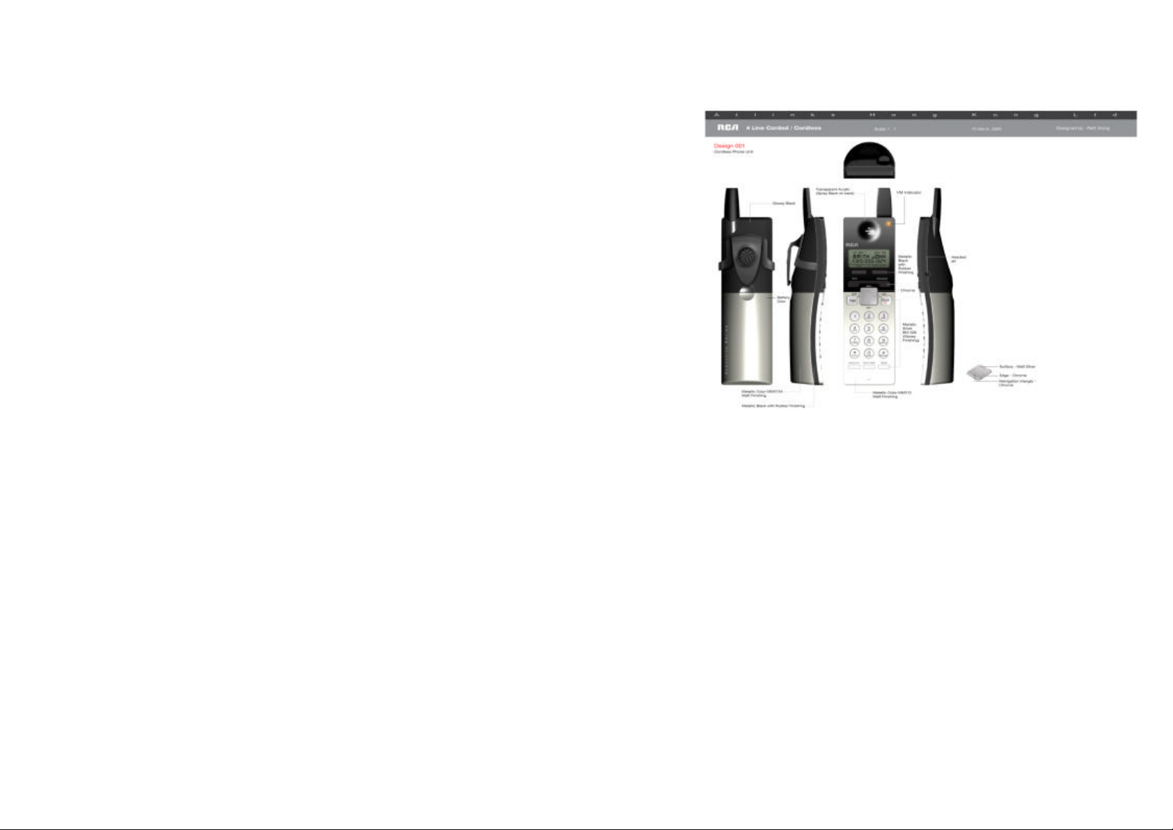
Handset Illustration
Page 7

13
Handset Controls and Display
14
1. VM Indicator: flashes when there are unrea d new voice mail
message
2. Receiver: voice output in non-speakerphone operation
3. 4-line LCD (Liquid Crystal Display):
a. The LCD display has LED (Light Emitting Diode) for
backlighting, LED dims after 10 seconds of inactivity.
b. The first line of LCD can be used to display either up to 16
characters of status or message, or it can be used to
display status icons , from left to right:
i) RSSI (Receive Signal Strength Indicator)
• During a call, the number of bars is proportional to
the radio signal strength received
ii) Handset ID
• Displays a 2-digit Handset ID
iii) Line Indicators
• Indicates the line number(s) being accessed or
held by the handset
iv) Battery Strength Indicator
• Number of bars is proportional to the amount of
battery time remaining
• Indicates charging when in charger cradle
c. The second and third lines of the LCD, up to 16 characters
each, display status, message, menu selections, or usereditable alphanumerical characters
d. The last line displays the left and right soft key functions
when needed
4. Left/Right Soft Keys: make soft key functions selection
5. Exit: exit menu operation
6. Speaker: turn on/off speakerphone
7. TALK: to place a telephone call or to answer a telephone or
intercom call
8. Up(? )/Down(? ) Scrolling Keys”
a. Scroll through records and menu selections
b. Adjust ringer volume during standby
c. Adjust receiver/speakerphone/headset voice volume
during talk
9. Left(? )/Right(?) Scrolling Keys:
a. Move cursor during number and name editing
b. Access CID and Directory during standby
10. END:
a. Ends a call
b. Press for 3 seconds to turn on/ off the power
11. Keypad
12. Intercom: to places an intercom call to another handset or a
group
13. Voice Mail: access Voice Mail functions
14. Flash:
a. Sends a Flash signal to phone line to retrieve a dial tone
after the call ends
b. To perform the call waiting feature provided by local
phone companies during a call
15. Microphone: voice input
16. Headset Jack: 2.5 mm standard headset jack
17. Speakerphone:
a. Voice output during speakerphone operation
b. Rings to an incoming call
c. Distinctive alert sounds indicating various events:
i) Single short beep: successful key entry
ii) Double short beep: power on/off
iii) Triple short beep: : failed operation or invalid key entry
iv) Single long beep: successful operation
v) Periodic 1-long-2-short beep (every 5 minutes): low battery
warning
vi) Periodic long series of beeps (repeat every 30 seconds):
indicates a call is on-hold
18. Belt Clip
19. Battery: 3.6V Li-Ion Handset battery
Page 8
15
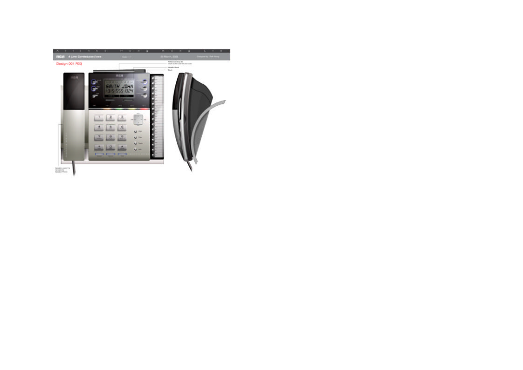
Base Unit Illustration
16
1. Base Unit corded handset (Handheld)
2. Speakerphone Speaker (under the Handheld):
a. Voice output during speakerphone operation
b. Rings to an incoming call
c. Distinctive alert sounds indicating various events:
3. Auto Attendant (AA):
a. When enabled (default for all 4 lines), AA will route an
b. AA can be enabled/disabled separately for each line, the
c. Press AA button to access AA functions
4. DND (Do Not Disturb): silent ring on all incoming calls, LED
flashes if DND is turned on
5. Exit: exit menu operation
6. 4-line LCD (Liquid Crystal Display):
a. The LCD display has LED (Light Emitting Diode) for
b. The first line of LCD can be used to display either up to 16
Base Unit Controls and Display
i) Single short beep: successful key entry
ii) Double short beep: power on/off
iii) Triple short beep: : failed operation or invalid key entry
iv) Single long beep: successful operation
v) Periodic 1-long-2-short beep (every 5 minutes): low battery
warning
vi) Periodic long series of beeps (repeat every 30 seconds):
indicates a call is on-hold
incoming call to a single extension or page a group of
extensions
AA button is lit if AA is turned on for any line
backlighting
characters of status or message, or it can be used to
display Auto Attendant and Voice Mail indicators, as well
as a battery icon:
i) A shown line number under the Auto Attendant field
indicates Auto Attendant is ON for that line
ii) A shown line number under the Voice Mail field
indicates Voice Mail is ON for that line
iii) During power outage, the backup battery will become
active, and a battery icon will be displayed in the
Page 9

17
middle with the number of bars proportional to the
18
amount of the battery time remaining
iv) A flashing battery icon with a cross indicates a
malfunction of the backup batter, immediate
replacement of the battery is recommended
c. The second and third lines of the LCD, up to 16 characters
each, display status, message, menu selections, or usereditable alphanumerical character s.
d. The last line displays the left and right soft keys
7. Left/Right Soft Keys: make soft key functions selection
8. Voice Mail (VM):
a. When enabled (default for all 4 lines), VM will record voice
messages if an incoming call is not answered by the
destination extension (HS or the BU)
b. There are 17 voice mailboxes total, one mailbox for each
of the 16 handset Ids (ID=01 -16), 1 general mailbox for
the base unit (ID=00)
c. VM can be enabled/disabled separately for each line, the
Voice Mail button is lit if the Voice Mail is turned on for any
line
d. Voice Mail button flashes when there are unread new
voice mail messages in the general mailbox. The LED will
continue to flash until all new messages in the general
mailbox have been played
e. Press Voice Mail button to access the voice mail functions
f. All mailboxes are password protected, default password =
0000
g. Voice messages are saved on flash memory which are
maintained even during power outage and backup battery
failure
9. Store: to store speed dial numbers
10. Intercom: to place an intercom call to a handset or a group
11. Speed Dial buttons: the 16 buttons on the right panel have
dual functions. They can be used as one- touch paging to
page a handset, or they can be used as speed dial to dial an
external phone number
12. Dial: press to access a telephone line, a line will be selected
by the Base Unit and dial tone will appear
13. Line Buttons and Status Indicators:
a. Press a line button to access a specific telephone line
b. Dual-colored LEDs indicate whether the line is idle (LED
off), ringing (flashing red), on hold (flashing red if held by
Handset, flashing green if held by Base Unit), or being
used by a Handset (red) or the Base Unit (green)
14. Up(? )/Down(? ) Scrolling Keys
a. Scroll through records and menu selections
b. Adjust ringer volume during standby
c. Adjust receiver/speakerphone/headset voice volume
during talk
15. Left(? )/Right(?) Scrolling Keys
a. Move cursor during number and name editing
b. Access CID and Directory functions during standby
16. Page: page all handsets
17. Flash:
a. Sends a Flash signal to phone line to retrieve a dial tone
after the call ends
b. To perform the call waiting feature provided by local
phone companies during a call
18. Redial: show last dialed number, can use up/down key to
scroll through additional 9 last dialed numbers
19. Hold:
a. Can place up to 4 lines on hold, only the extension putting
a line on hold can un-hold that line
b. There is a 30-minute time out on a held call
20. Headset:
a. Press to activate headset operation
b. Supports standard 2.5 mm headset plug
c. Headset operation remains for the duration of the call until
the Speaker button is pressed or the BU Handheld is
picked up
d. Press Headset button again to hang up
21. Speaker:
Page 10

19
a. Press to activate speakerphone operation
20
b. Speakerphone operation remains for the duration of the
call until the Headset button is pressed or the BU
Handheld is picked up
c. Press Speaker button again to hang up
22. Mute:
a. Mute BU Handheld or speakerphone microphone
b. Press Mute again to exit mute state
23. Supports up to 4 analog line interface (RJ-14 x 2, RJ-11 x 2)
24. DC In: to plug in the AC/DC Power Adaptor
25. Backup Battery:
a. Rechargeable NiMH battery
b. Active during AC power outage
c. When fully charged, can provide about 20 minutes of
normal ope ration
26. Reset button (on the bottom of the BU):
a. Reset button is indented to prevent accidental reset
b. Restores Base Unit to factory settings
c. All VM, AA, CID, DIR records will be erased, handsets
need to be re-registered after a Base Unit reset
Installations
1. Installing the Base Unit Handset (Handheld)
a. Connect one end of the Handheld cord to the Handheld
and the other to the Handheld jack located on the left side
of the Base Unit.
b. Use only supplied RCA 25450 Handheld.
2. Installing the Backup Battery in the Base Unit
a. A rechargeable NiMH backup battery is supplied which
can provide emergency power during an AC power outage
b. Open the battery cover located on the back of the Base
Unit.
c. Insert the battery connector into the backup battery jack
d. The backup battery can provide about 20 minutes of
normal operation
e. The backup battery is charged while the base unit is on
AC power
f. Charge the backup battery for 10 hours before first use
g. During an AC power outage, the backup battery will
become active and a battery icon is shown on the top of
the Base Unit LCD display. When the battery is low, the
icon will flash.
h. Use only supplied RCA 25450 Base Unit backup battery
3. Installing the Base Unit
a. Raise the Base Unit antenna to upright position
b. Make sure the Base Unit antenna is free of obstacles in its
close proximity
c. For best reception, place the Base Unit on a well
ventilated flat surface located on a high ground
d. For best performance, maintain at least a distance of 1
meter (about 3 feet) between the Base Unit and other
electronic devices (e.g., TV, computer, stereo, fax
machine, answer machine, etc.)
4. Connecting the Telephone Cords
a. If your telephone lines are of 2-wire, 1-line type known as
RJ-11, plug one end of the phone cord into one of the 4
phone jacks marked L1 – L4 and plug the other end into
the telephone outlet. The RCA 25450 has a built-in “Line
Detection” feature; it is okay to plug in the phone jacks in
random order.
Page 11

21
b. If your telephone lines are of 4-wire, 2-line type known as
22
RJ-14, you should plug a RJ -14 connector into Base Unit
telephone line jacks mark L1 or L3.
c. The telephone cords supplied work for either type of
interface.
5. Installing the Base Unit AC Adaptor
a. Plug the transformer end of the Base Unit AC/DC adaptor
(7.5V) into a standard AC electrical power outlet, plug the
other end into the “DC In” jack on the back of the Base
Unit
b. To ensure uninterrupted services, the Base Unit’s AC/DC
Adaptor is best plugged into a UPS (Uninterruptible Power
Supply).
c. The base adaptor’s DC plug is larger in dimension than
the wireless handset charger’s DC plug. The charger
adaptor’s DC plug will not fit into the base’s DC-In jack.
6. Installing the Handset Battery
a. Insert the handset battery into the handset battery
compartment
b. Charge the handset battery pack for 4 hours until the
handset battery strength indicator on the handset LCD
display is full before the first us age.
7. Installing the Handset Charger AC Adaptor
a. Plug the transformer end of the Charger AC/DC Adaptor
(5.5V) into a standard AC electric power outlet, plug the
other end into the “DC In” jack on the back of the Charger.
b. The Handset Charger adaptor’s DC plug is smaller in
dimension than the Base Unit adaptor’s DC plug. The
charger adaptor’s DC plug will not fit into the base’s DC-In
jack
c. During an AC power outage, the charger will not be
charging the handset battery. To ensure uninterrupted
services, the charger’s AC/DC Adaptor is best plugged
into a UPS (Uninterruptible Power Supply).
Important Notes:
a. Recommended phone line features from the local phone
company:
i) Caller ID (Type I): allowing the display of incoming
caller information
ii) Hunt Group: Multiple phone lines “hunt group” is a
useful feature and works well with this phone system.
This feature “ties” multiple phone lines to a single
phone number. When an outside caller calls this
common phone number, the phone company
automatically finds a free line. In a hunt group, the
Call Waiting and the Caller ID with Call Waiting (or
called Type II Caller ID) features are unnecessary
because a 2nd call will come in on a separate line,
rather than on the same line. For a 2nd call coming in
on a separate line, the phone system’s built- in Second
Incoming Call feature will alert the user and allow the
user to toggle between multiple lines
b. The handset packaged along with a Base Unit is pre-
registered at the factory. If you have a new handset, you
will need to register the handset with the Base Unit in
order to be recognized as a member handset by the base
and by other handsets. See Handset Registration.
c. If the RCA 25450 is connected behind a PBX which does
not support the Caller ID feature, your RCA system won’t
be able to receive caller information and thus cannot
display and record the information.
Page 12

23
Summary of Features
24
The RCA 25450 Telephone System is pretty much plug-and-play
after you have read and understood the installation guides and the
basic controls and displays on the Handset and the Base Unit. No
Base Unit or handset programming is needed for basic operations.
However, this feature-rich telephone system provides many
advanced feature that are also easy to use and can greatly
enhance your productivity. A summary of features and their
benefits is listed below. You are encouraged to read through this
section and explore the features later at your leisure.
1. System Features:
a. 900 MHz band frequency hopped TDMA (Time Division
Multiple Access):
• Provide secure and high quality communications
• Avoid interference with 2.4GHz and 5 GHz WLAN
(Wireless Local Area Network, 802.11x) and
microwave equipment
• Low handset average transmit power (less than 50
mW) reducing human exposure to radio wave
b. High receiver sensitivity:
• Better coverage than other 900 MHz, 2.4 GHz and 5
GHz commercial telephone systems
• Less communications dead spots
c. 4-line switching capability on the Base Unit
d. System ID: randomly selected from 65,536 possible codes,
avoiding unauthorized use
e. Supports up to 16 remote handsets (HS) and 4 groups:
• No telephone connection required to the remote
handset locations
• Handset can subscribe up to 4 groups
f. Handset intercom independent of the Base Unit:
• Handsets can intercom without the presence of the
base
• Intercom calls are digital and full duplex
• Handset intercoms do not take up Base Unit’s radio or
line resources
2. Base Unit (BU) Features:
a. Auto-Attendant (AA):
• AA for all 4 lines can be active at the same time in
case of 4 simultaneous incoming calls
• Per line AA enable/disable with LCD indicator: When
disabled for a line, all incoming calls can be preprogrammed to ring all handsets or a particular
handset or a group of handsets. If set to ring one
handset or a group of handsets, only that handset or
group of handsets can make outgoing calls through
that line as well.
• Up to 5 custom AA greeting messages: maximum 64
seconds each, can be custom-recorded
• Each line can choose its own greeting message
• AA can only be enabled/disabled from the BU
b. Backup Battery: provide 20 minutes of emergency power
c. Call Log:
• Records last 50 incoming calls, up to 25 digits each
for telephone numbers and 16 characters each for
names (needs Caller ID service from telephone
service provider)
• One-button access to Call Log during standby by
pressing the Right arrow key and then use Up/Down
arrow keys for scrolling
d. Call Timer: display call duration on LCD display
e. Call Transfer:
• Direct Transfer: call transfer to another handset
without announcement
• Announced Transfer: call transfer to another handset
with announcement
f. Caller ID (CID):
• Supports FSK format Type I Caller ID
• Supports FSK format Type II Caller ID (Call Waiting
with Caller ID, which allows the display of 2nd
incoming call information on the same phone line
when 1st call is in progress)
• Both Type I and Type II Caller ID are service provider
(your local phone company) features, subscription to
these features are required
g. Corded Handhel d, Speakerphone and Headset
h. Dialing Prefix: up to 14 digits, including pause(s), an
access code or credit card number can be preprogrammed to be automatically added when dialing from
Page 13

25
Call Log and Directory or when dialing by entering number
26
first
i. Directory:
• 100 alphabetically sorted and searchable names
• Each entry can store up to 25 -digit phone number and
16-character name
• Can dial from display
• During stand -by, you can enter the directory by
pressing the Left arrow key and then use Up/Down
keys for scrolling
j. DND (Do Not Disturb): silent ring on all incoming calls
k. Flash Time: 100 ms – 1000 ms selectable, applicable to
all 4 lines, default value = 600 ms
l. Group Paging:
• Page all handsets
• Enter group ID to page several handsets
m. Hold:
• Can place up to 4 lines on hold, only the extension
putting a line on hold can un-hold that line
• There is a 30 -minute time out on a held call
• A 30- second On-Hold-Message can be custom
recorded and played back periodically
n. LCD:
• 4-line with Time and Date displays
• 5-level LCD contrast adjustment
o. Line Detection: automatically check for unplugged or bad
line connections for outgoing calls
p. Line Selection: can select from a specific line for an
outgoing call
q. Mute
r. Number Formatting: when viewing CID records, phone
numbers can be edited for outgoing call
s. Redial: can perform last-number -redial on 10 previously
called numbers
t. Ring Voltage: detect ring voltage as low as 20 Vrms, can
be connected behind most PBX systems
u. Second Incoming Call: alert the arrival of another call on
another line
v. Sound Type Selections:
• 4 ringer types
• 4 key tone types
w. Sound Volume Adjustments:
• 6-level voice volume
• 5-level ringer volume (high/low/vibrate/vibrate- then-
ring/off)
• 3-level key tone volume control (high/low/off)
x. Speed Dial: 16 one-touch speed dial buttons
y. Three-way Conferencing: supports 2-HS+1- line, 2-line+1-
HS, 1-HS+BU+1-line, BU+2-line three-way conferencing
z. Tone (DTMF) and Pulse Dialing, default is Tone
aa. 2.5 mm standard headset jack, auto-answer can be
enabled when operating with a headset
bb. User IDs: 21 total (17 extensions and 4 groups)
• ID 00: Base Unit
• ID 01- 16: Handsets
• ID 91- 94: group ID, handset can “subscribe” from
handset menu to groups and be paged when a group
ID is entered by a line caller or an intercom caller
cc. Voice Mail:
• Total 17 mailboxes (one each for the 16 handsets plus
the Base Unit) and 100 minutes of recording time
• All mailboxes are password protected
• 2-channel Voice Mail allows two person accessing
mailboxes simultaneously
• Administrator can clear all mailboxes without changing
mailbox passwords
• Administrator can enter or clear a particular mailbox
after changing its password
• Per line VM enable/disable with LCD indicator. When
disabled for a line, all incoming calls on that line will
not be routed to any mailbox
• If AA is turned on, the VM is automatically enabled as
well.
• If the AA is off and VM is off, the designated
handset(s) will continue ringing
• If the AA is off and VM is on, the unanswered call will
be answered by the designated handset’s mailbox or
the general mailbox (if designated to all handsets or a
group of handsets)
• The VM button on the base will be lit if any VM is on
for any line, and flash if when there are new
messages in the general mailbox
• Voice messages are saved on flash memory which
are kept even during power outage and backup
battery failure
Page 14

27
• Recording time limit for each message is 64 seconds,
28
no time limit per line or per extension
• VM can only be enabled/disabled from the BU
• Remote landline access to voice mailboxes
3. Handset (HS) Features:
a. Any key answer (except END and two Soft Keys)
b. Battery:
• 3.6 V Li-Ion
• Battery strength display and low battery alert tone
c. Call Forwarding:
• Forward all incoming calls to another handset or an
outside line after 3 rings to the extension
• Once enabled from the handset, all phone calls will be
routed to the designated number until disabled. A
warning message will appear on the LCD
• Intercom calls are not forwarded.
• Before setting this feature, please check your PBX
system if it can send a line reverse signal to hang up
the line
d. Call Log:
• Records last 50 incoming calls, up to 25 digits each
for telephone numbers and 16 characters each for
names (needs Caller ID service from telephone
service provider)
• One-button access to Call Log during standby by
pressing the Right arrow key and then use Up/Down
arrow keys for scrolling
e. Call Transfer:
• Direct Transfer: call transfer to another handset
without announcement
• Announced Transfer: call transfer to another handset
with announcement
f. Charger:
• Separate charger, no need for wiring
• 4 hours charge from empty
g. Dialing Prefix: up to 14 digits, including pause(s), an
access code or credit card number can be preprogrammed to be automatically added when dialing from
Call Log and Directory or when dialing by entering number
first
h. Directory:
• 100 alphabetically sorted and searchable names
• Each entry can store up to 25 -digit phone number and
16-character name
• Can dial from display
• During stand -by, you can enter the directory by
pressing the Left arrow key and then use Up/Down
keys for scrolling
i. DND (Do Not Disturb) : silent ring on all incoming calls
j. Group Paging: enter group ID to page several extensions
k. Headset and Speakerphone
l. Hold:
• Can place up to 4 lines on hold
• Can perform battery swap during hold
m. Intercom:
• Handset-to-handset or handset -to-base Intercom
• Handset-to-handset intercom is performed
independent of base
n. Key Guard: prevents accidental dialing
o. LCD:
• 4-line with call duration display
• 5-level LCD contrast adjustment
p. Line Selection: when enabled, handset can select from a
list of available lines for an outgoing call
q. Mute
r. Redial: can perform last-number -redial on 10 previously
called numbers
s. Ringer vibrator
t. Second Incoming Call: alert the arrival of another call on
another line
u. Sound Type Selections:
• 4 ringer types
• 4 key tone types
v. Sound Volume Adjustments:
• 6-level voice volume
• 5-level ringer volume (high/low/vibrate/vibrate- then-
ring/off)
• 3-level key tone volume control (high/low/off)
w. Three-way Conferencing: supports 2-HS+1- line, 2-line+1-
HS, 1-HS+BU+1-line, BU+2-line three-way conferencing
x. 2.5 mm standard headset jack, auto -answer can be
enabled when operating with a headset
y. VM (Voice Mail) Message Alert
Page 15

29
Basic Operations
30
Making a Telephone Call
1. From a Handset:
a. Press the TALK or Speaker, and then enter phone number
b. Or, you can enter phone number first then press the TALK
or Speaker key. When using this method, you can use the
CLEAR (Left) and DELETE (Right) soft keys to edit the
number entered. “Delete” erases the last digit entered.
“Clear” erases the entire line but remains in the dialing
mode
c. To abort dialing at any time, press the END key
2. From the Base Unit:
a. Press the Dial, or Speaker, or Headset button, or pick up
the Handheld, and then enter the phone number
b. Or, you can enter phone number first then press the Dial,
or Speaker, or Headset button, or pick up the Handheld
(off-hook). When using this method, you can use the
CLEAR (Left) and DELETE (Right) soft keys to edit the
number entered. “Delete” erases the last digit entered.
“Clear” erases the entire line but remains in the dialing
mode
c. To abort dialing at any time,
i) Press the Speaker button if dialing by pressing Dial or
Speaker button
ii) Press the Headset button if dialing by pressing the
Headset button
iii) Return the Handheld to cradle (on-hook) if dialing by
picking up the Handheld
Notes:
a. If all lines are busy or designated for other handsets, the
LCD shows “No line available” and then returns to standby
b. If an air link cannot be established, the LCD will show “No
connection” after a 15-second time out.
c. A call duration timer will start displaying the length of the
call after the link is established
d. Before the TALK/Dial/Speaker/Headset button is pressed
or the Handheld is pickup, an incoming call takes priority
and will abort the dialing.
Receiving a Telephone Call
1. On a Handset:
a. When an incoming call arrives, the ringer will ring or
vibrate unless the ringer has been turned off
b. If the handset is on the charger cradle (ringer will be
temporarily switched to “Ring” if it has been set to
“Vibrate”).
c. If the handset is not on the cradle, press any key (except
END and the SILENT and OPTION soft keys) to answer;
pressing Speaker will start speakerphone operation
d. To switch between Speakerphone and Receiver/Headset:
i) Press Speaker to switch from Receiver or Headset to
Speakerphone
ii) Press TALK to switch from Speaker to Receiver
iii) Plug in Headset to switch from Receiver or Speaker to
Headset
iv) Unplug Headset will return the voice output to the
Receiver
2. On the Base Unit:
a. When an incoming call arrives, the ringer will ring unless
the ringer has been turned off or the DND button has been
pressed and remain effective
b. The Line Status LED will flash along with the rings on the
line from which the call comes in
c. To answer,
i) Press the Line Button corresponding to the flashing
Line Status LED to start conversation with
speakerphone, or
ii) Pick up the Handheld, or
iii) Press Speaker to start conversation with
Speakerphone, or
iv) Press Headset to start conversation with headset
d. To switch between Headset, Handheld and Speakerphone,
i) Press Headset to switch from Speakerphone or
Handheld to Head set, make sure that headset has
been plugged in
ii) Press Speaker to switch from Handheld or Headset to
Speakerphone
iii) Pick up Handheld to switch from speakerphone or
Headset to Handheld
Page 16

31
Notes:
32
a. The Handset LCD will show “Incoming call from Line x,”
where x represents the line number from which the call
comes in.
b. After the incoming call is answered or after the Caller ID
information is received, the incoming line number
information will be move to the Line Indicator icon on top
of the Handset LCD display.
c. If Caller ID service is available, the LCD will display the
incoming Caller ID information. If the LCD shows “Private”
or “Unknown”, the caller’s information may have been
blocked by the caller or the originating phone company
d. Press SILENT (Left) soft key on either the Handset or the
Base Unit, or the DND (Do Not Disturb) button on the
Base Unit, if you choose to ignore the call. Unlike turning
off the ringer (from the menu), the SILENT key operation
is valid only for the current call. The DND key has the
same effect as turning off the ringer. Press the DND
button again to allow calls.
e. During an incoming ring, the Handset or the Base Unit can
ignore the call and still make an outbound telephone or
intercom call. Handset can make an outgoing telephone
or interc om call through the OPTION soft key (select “Line
call” or “Intercom” in its submenu). The Base Unit has an
additional method which is to press the Line Button to
access an outside line.
Making an Intercom Call
1. From a Handset:
a. Press Intercom key followed by a two-digit handset ID (01-
16) or a Group ID (91-94)
b. To abort intercom before the recipient answers, press the
END key
2. From the Base Unit
a. Press one of the 16 one-touch speed dial keys, from top to
bottom, for Handset 01 -16, or
b. Press Intercom key followed by a two-digit handset ID (01-
16) or a Group ID (91-94). Note that speed dial is not
applicable when calling a group (ID = 91-94)
c. To abort intercom before the recipient answers, press the
Exit key
Notes:
a. Intercom calls between handsets can be made regardless
if the Base Unit is present.
b. If a Group ID is entered, the first extension (belonging to
that group) that answers will establish a link with the caller.
See Group Subscription.
c. If a valid ID is not entered within 15 second, the calling
party will return to its previous state (standby or hold)
d. Intercom paging has a time out of 30 seconds if no one
answers.
e. In the case that the Base Unit is already processing 4
voice channels (line call, voice mail, auto attendant), the
base will not be able to intercom other handsets. The
Base Unit LCD will display “System busy”
Receiving an Intercom Call
1. On a Handset:
a. When an intercom call arrives, the ringer will ring or
vibrate unless the ringer has been turned off. Press any
key (except END and the SILENT and OPTION soft keys)
to answer the intercom call , or press Speaker to answer
through speakerphone
b. If the handset is on the charger cradle (ringer will be
temporarily switched to “Ring” if it has been set to
“Vibrate”).
c. To switch between Speakerphone and Receiver/Headset:
i) Press Speaker to switch from Receiver or Headset to
Speakerphone
ii) Press TALK to switch from Speaker to Receiver
iii) Plug in Headset to switch from Receiver or Speaker to
Headset
iv) Unplug Headset will return the voice output to the
Receiver
2. On the Base Unit:
a. When an intercom call arrives, the ringer will ring unless
the ringer has been turned off from menu or the DND is in
effect.
b. To answer,
i) Press the Intercom button to start conversation with
speakerphone, or
Page 17

33
ii) Pick up the Handheld, or
34
iii) Press Speaker to start conversation with
speakerphone, or
iv) Press Headset to start conversation with headset
c. To switch between Headset, Handheld and Speakerphone,
i) Press Headset to switch from Speakerphone or
Handheld to Headset, make sure that headset has
been plugged in
ii) Press Speaker to switch from Handheld or Headset to
Speakerphone
iii) Pick up Handheld to switch from speakerphone or
Headset to Handheld
Notes:
a. The LCD displays the caller’s Extension ID (00-16).
b. Press SILENT (Left) soft key on either the Handset or the
Base Unit, or the DND (Do Not Disturb) button on the
Base Unit, if you choose to ignore the call. Unlike turning
off the ringer (from the menu), the SILENT key operation
is valid only for the current call. The DND key has the
same effect as turning off the ringer. Press the DND
button again to allow calls.
c. During an incoming ring, the Handset or the Base Unit can
ignore the call and still make an outbound telephone or
intercom call. Handset can make an outgoing telephone
or intercom call through the OPTIO N soft key (select “Line
call” or “Intercom” in its submenu). The Base Unit has an
additional method which is to press the Line Button to
access an outside line.
Ending a Call
To end a telephone or intercom call,
1. On a Handset:
a. Press END key or place handset into charging cradle
2. On the Base Unit:
a. Press Speaker if in Speakerphone operation
b. Press Headset if in Headset operation
c. Place Handheld back to cradle if using Handheld
Making a Page from the Base Unit
The Page button on the Base Unit key is a one-touch button to
intercom all handsets.
1. Press the Page button, the Base LCD will show “Paging all…”
2. The first handset to answer establishes a one-to-one link with
the Base Unit
3. To switch between Headset, Handheld and Speakerphone on
the Base Unit,
a. Press Headset to switch from Speakerphone or Handheld
to Headset, make sure that headset has been plugged in
b. Press Speaker to switch from Handheld or Headset to
Speakerphone
c. Pick up Handheld to switch from speakerphone or
Headset to Handheld
Notes:
a. The Hand sets’ LCD displays “Incoming page from Ext
#00”
b. Press SILENT (Left) soft key on the Handset if the
Handset chooses to ignore the page. Unlike turning off
the ringer (from the menu), the SILENT key operation is
valid only for the current page.
c. During an incoming ring, the Handset can ignore the call
and still make an outbound telephone or intercom call by
using the OPTION soft key and select “Line call” or
“Intercom” from its submenu.
d. In the case that the Base Unit is already processing 4
voice channels (line call, voice mail, auto attendant), the
base will not be able to page other handsets. The Base
Unit LCD will display “System busy”
Redial
1. From a Handset:
a. Press the REDIAL (Left) Soft Key
b. The LCD shows the first record in the 10-entry Redial Log,
starting from the most recent number called
c. Use Up/Down arrow keys to scroll through the 10 records
Page 18

35
d. To dial the displayed number, press the TALK button or
36
Speaker button for Speakerphone operation
e. Press END to abort the redial
2. From the Base Unit:
a. Press the RE DIAL (Left) Soft Key
b. The LCD shows the first record in the 10-entry Redial Log,
starting from the most recent number called
c. Use Up/Down arrow keys to scroll through the 10 records
d. To dial the displayed number,
i) Press the Dial button, or
ii) Press the Speaker button for Speakerphone, or
iii) Press the Headset button for Headset, or
iv) Press one of the idle Line Button (Line 1-4) for
Speakerphone, or
v) Lift the Handheld
e. To abort the redial,
i) Press the Speaker button again if redial by pressing
the Speaker or Dial button, or
ii) Press the Headset button again if redial by pressing
the Headset button, or
iii) Press the Speaker button again if redial by pressing
one of the idle Line Button (Line 1-4), or
iv) Return the Handheld back to cradle (on-hook)
Notes:
a. When scrolling through the last 10 dialed numbers, the
LCD will display two soft key options: SAVE (Left) and
DELETE (Right). Press SAVE will enter Directory edit
mode, allowing the editing of number and name. Pressing
the DELETE will delete the displayed record from the last-
10 lis t. The deletion will have a confirmation prompt
YES/NO.
b. If the Last-10 Called list is empty, the LCD will display
“Redial log empty”.
c. Intercom numbers are not stored in the last 10 numbers
dialed log.
d. There is a 15-second time out if no number is dialed after
entering the redial mode. The Handset or Base Unit will
return to standby.
e. If an incoming (line or intercom) call arrives before a
number is dialed, the Handset or Base Unit will abort the
redial operation and enter the incoming call state.
Adjusting Voice Volume
1. For both the Handset and the Base Unit, the voice volume can
only be adjusted during a call
2. There are 6 levels of volume selections. Default as volume 4.
Use Up (Vol+) and Down (Vol-) arrow keys to adjust
3. The new setting remains effecti ve for all future calls until
changed
Adjusting Ringer Volume
1. For both the Handset and the Base Unit, the ringer volume
can be adjusted in standby using the Up/Down arrow keys
directly, or in menu selection.
2. Default volume settings for both Handset and Base Unit are
“Medium.”
3. Adjusting ringer volume using Up/Down arrow keys while in
standby:
a. Pressing the Up (Vol+) and Down (Vol -) arrow keys, the
LCD display will show available options
b. Use Up/Down arrow to scroll through options
c. For the Handset and the Base Unit, the ringer volume can
be selected from 4 options: High, Medium, Low, and Off.
d. At each volume option, the ringer will sound once
exemplifying the volume level
e. Press the Exit button on the Base Unit or the END button
on the Handset to select the displayed option
f. The displayed option will be automatically selected after 5
seconds of inaction
4. Adjusting ringer volume using menu selection:
a. On the Handset or the Base Unit, press the MENU (Right)
soft key to enter the Main Menu
b. Use Up/Down arrow keys to scroll through Main Menu
items
c. When “Sound” option appears on the LCD, press SELECT
(Left) soft key
Page 19

37
d. Use Up/Down arrow keys to scroll through “Sound”
38
submenu items
e. When “Ring volume” option appears on the LCD, press
SELECT (Left) soft key
f. Use Up/Down arrow keys to scroll through “Ring volume”
submenu items. At each volume option, the ringer will
sound (or vibrate) once exemplifying the volume level
g. For the Base Unit, the ringer volume can be selected from
4 options: High, Medium, Low, and Off. For the Ha ndset,
there are 6 options: High, Medium, Low, Vibrate, Vibrate
and High, and Off, where “Vibrate” means vibration only,
and “Vibrate and High” will produce both vibration plus a
ring tone with High volume.
h. When the desired ringer volume option appears on the
LCD, press SELECT (Left) soft key and returns to the
Main Menu screen
i. Press the Exit button on the Base Unit or the Handset to
return to standby
Notes:
• Until a selection is saved, an incoming call or intercom
paging will take priority and the ringer s etting operation will
be aborted.
Setting Time and Date on the Base Unit
1. On the Base Unit during standby, press the MENU (Right) soft
key to enter the Main Menu.
2. Use the Up/Down arrow keys to find “Phone setting” and then
press SELECT (Left) soft key to enter the phone setting
submenu.
3. Use the Up/Down arrow keys to find and select “Set time”
4. Enter the current Month, Date, Hour and Minute, each a two digit number. A number less than 10 should be entered with a
“0” prefix. For example, June 21 should be entered as 06/21.
The “/” is automatically generated.
5. Press SAVE (Left) soft key to save the input
6. Use Up/Down arrows to find and select AM or PM
7. Press SAVE to save the selection.
Notes:
a. Use the BACK (Right) soft key to return to the previous
menu display if entered incorrectly.
b. Time and Date will be updated by the latest Caller ID data
received from the local phone service provider.
Putting Call(s) on Hold
1. On a Handset:
a. When a call is in progress, it can be put on hold by
pressing the OPTION (Right) soft key and then select the
“Hold” option from the submenu.
b. LCD will display “Call(s) on hold” whenever there is at
least one call being on hold, up to 4 lines can be held by a
handset. At the Base Unit, the Line Status LED will flash
red indicating the corresponding line is being held by a
Handset.
c. To return to the conversation, press UNHOLD (Right) soft
key on the Handset, the LCD will display “Line to unhold”
followed by a list of lines being on hold. Use Up/Down
arrow key to scroll to the desired line to unhold, then press
SELECT (Left) soft key.
2. On the Base Unit:
a. When a call is in progress, it can be put on hold by
pressing the Hold Button.
b. LCD will display “Call(s) on hold” whenever there is at
least one line being on hold, up to 4 lines can be held by
the Base Unit. In addition, the corresponding Line Status
LED will flash green indicating the line is being held by the
Base Unit.
c. To return to the conversation, press the Line Button for the
desired line number. However, if the line is already
released from the hold state (due to time out or hung up
by the far end), pressing the Line Button will be assumed
to be making an outgoing call.
Notes:
Page 20

39
a. While putting call(s) on hold, the Handset or the Base Unit
40
can access Directory or Call Log, make an outgoing call or
intercom/page, or take an incoming call or intercom.
b. The call being placed on hold can only be UNHOLD by the
Handset or the Base Unit that puts it on hold, or unless the
hold state exceeds the 30- minute limit.
c. An alert tone (double beep) every 30 seconds will remind
the Handset or the Base Unit that call(s) which has placed
call(s) on hold. The alert tone will start after the first call is
placed on hold and will continue until all on-hold calls have
been released. The alert tone will not be played while the
Handset or the Base is talking on another line. However,
the alert tone will resume when the Handset or Base Unit
returns to idle.
d. The Handset can be powered off (e.g., change battery)
while putting call(s) on hold. After power on again, the
handset LCD display will display “Call(s) on hold”.
e. Unhold call(s) by a Handset can only be done when the
Handset is within the Base Unit’s coverage area.
Otherwise, the UNHOLD operation will fail with a “No
connection” message.
f. If a call is no longer on hold due to the 30-minute time out
or hung up by the far end, the handset will be notified that
the “Line x is not on hold” when attempting UNHOLD
operation.
Mute
1. After a link is established, you can press MUTE (Left) soft key
on the Handset or the Mute button on the Base Unit to mute
the handset, speakerphone, Handheld and headset
microphone
2. When mute is active, the other party will not hear your voice,
but you can still hear the other party
3. To end the mute, press UNMUTE (Left) soft key on the
Handset or the Mute button again on the Base Unit.
4. Mute is effective only for the current call
Do Not Disturb
1. On a Handset:
a. Enter the key sequence MENU – Sound – Ring volume,
then select “Off”. Press SELECT (Left) soft key to save
your choice. This will turn off the ringer until it is turn on
again from the menu.
b. For temporary silencing the ringer when an incoming call
arrives, press SILENT (Left) soft key
2. On the Base Unit:
a. Press the DND button, this will turn off the ringer until it is
turn on again by pressing the DND button again or turned
on from the menu.
b. Enter the key sequence MENU – Sound – Ring volume,
then select “Off”. Press SELECT (Left) soft key to save
your choice. This will turn off the ringer until it is turn on
again by pressing the DND button again or turned on from
the menu.
c. For temporary silencing the ringer when an incoming call
arrives, press SILENT (Left) soft key
Key Guard (Handset Only)
1. To prevent accidental dialing on a Handset, press MENU
(Right) soft key, then select “Key guard” option. The handset
keypad is locked. No key entry is accepted including the END
(power on/off) key.
2. To unlock the keypad, press UNLOCK (Left) soft key, then,
within 2 seconds, press the digit “1” to unlock.
3. Key Guard is in effect until unlocked or the battery is removed.
Viewing Call Log
1. Press Right (CID) arrow key to enter the Call Log which is a
list of last 50 incoming calls’ Caller ID information, starting
from the most recent one. Each record includes telephone
number, name (if available), and time stamp (date and time of
call).
Page 21

41
42
2. The LCD displays will show the date and time of call on the
first line, followed by the name on the second line, and the
phone number on the third line. An unread record will have a
“NEW” at the end of the first line of display.
3. When viewing an incoming call record, you can make a call to
the viewed number, store the record on the Directory or the
Speed Dial (Base Unit) or delete the record.
a. To make a call to the displayed number:
i) From a Handset, press TA LK or Speaker button
ii) From the Base Unit, press DIAL, Speaker, Headset,
an idle Line Button, or pick up the Handheld
iii) The displayed Caller ID telephone number in most
cases will be a 10 -digit number with the 3-digit area
code followed by the 7-digit telephone number. The
FORMAT (Left) soft key can be used to modify the
telephone number to comply with the local dialing
rules. Pressing the FORMAT soft key once will add a
“1” in front of the displayed number. A second press
of the FORMAT key will remove the area code from
the Caller ID number. For example, suppose that the
telephone number stored in the Call Log is 425 -1234567, pressing the FORMAT key once will change the
displayed number to 1-425-123-4567, pressing the
FORMAT key again will change the displayed number
to 123-4567. Pressing the FORMAT key again will
loop back to 425-123-4567.
iv) Dialing the viewed number can only be made during
standby or on hold.
b. To save or delete the displayed Caller ID information into
the Directory, or to erase the entire Call Log:
i) Press the OPTION (Right) soft key
ii) Use the Up/Down arrow key to move to the desired
option from three possible actions: “Save”, “Delete”
and “Clear all”.
iii) Press the SELECT (Left) soft key to select.
iv) If “Save” is selected, the LCD display switches to
Directory editing screen where the name and phone
number can be edited and saved (See Directory
Operations).
v) The Base Unit can save the displayed telephone
number in one of its 16 Speed Dial buttons by
pressing the Store button; the LCD display will prompt
for a location. Select by pressing one of the 16 Speed
Dial keys. If the selected location already has a
number stored, the LCD display will show the name
and number and asks for overwrite confirmation.
Select YES (Left) soft key to overwrite or NO (Right)
soft key to return to the previous screen.
vi) Choose “Delete” or “Clear all” to erase the displayed
record or all records. A confirmation prompt (YES/NO)
will be displayed.
Notes:
a. Call Log will be empty if no Caller ID information is
available for incoming calls. Subscription to this feature is
required from your local telephone company.
b. Some of the information, e.g., name and/or time stamp,
may not be available even you have subscribed to the
Caller ID service. This available information is dependen t
on the local telephone company’s switch equipment.
c. If there is no record in the Call Log, pressing the Right
(CID) arrow key will return with a “No CID records”
message.
d. If no line is available for making an outgoing call while
viewing the Call Log, the Handset or the Base Unit will
sound an error tone and return to standby.
e. When storing the displayed number into the Base Unit
Speed Dial button while viewing the Call Log, the name
cannot be edited and the number can only be edited with
the FORMAT key.
Recording AA Main Greeting Message
When an incoming call arrives, if Auto Attendant is enabled
(default), it is first greeted by an Auto Attendant Main OGM (Out
Going Message) after 2 rings, with the default announcement of
“Please enter the extension number or press zero for the operator”.
After the caller enters the destination extension number (00-16),
the call will be routed to the respective extension. The call
destined for the operator will be routed to Extension 00, i.e., the
Base Unit.
To chang e the default Main OGM, which can only be done from
the Base Unit,
Page 22

43
1. Press the Auto Att button
44
2. The LCD displays the menu selection items for the Auto
Attendant
3. Use the Up/Down arrow key to find “Record OGM”, then select
with the SELECT (Left) soft key
4. Up to 5 OGM can be pre- recorded and played on different
lines (each line can have its own OGM) and/or different
occasions. The LCD displays prompts for selection of
recording OGM1-5.
5. Use the Up/Down arrow to select a number (1-5). After
pressing the SELECT (Left) soft key, a long beep will appear
indicating the start of recording.
6. Speak loudly and clearly to the Microphone. Up to 60 seconds
of greeting message can be recorded.
7. When finish recording, press the FINISH (Left) soft key to
return to the Record OGM menu.
8. Continue recording other OGM or press “BACK” to return to
the Auto Attendant menu where you can select “Play OGM”
option to play back the OGM that just recorded.
9. Press Exit button at any time to abort and return to standby.
Recording Mailbox Greeting Message
There are up to 17 Voice Mail mailboxes, one for each extension
(16 handsets, ID=01 -16, plus the Base Unit, ID = 00). Each
extension/mailbox can have its own greeting message. The
default greeting message for all mailboxes is “Please leave a
message after the tone”
Each mailbox is protected with a 4-digit password; the default
password for all mailboxes is 0000. Any Handset and the Base
Unit can access any mailbox as long as its password is known.
To change the default mailbox greeting message,
1. From a Handset:
a. Press the Voice Mail button
b. If the Handset can link with the Base Unit, the Handset
LCD will display “Enter VM box # and password”
c. Enter a 2- digit mailbox number followed by a 4-digit
password, for example, to access Mailbox 07 with a
password of 0000 enter 070000.
d. Unless the mailbox is currently in use, the LCD will display
the mailbox number being accessed on the first line, the
number of new and old messages on the second line, and
the available options on the third line. Use Up/Down
arrows to find and select “VM box option”.
e. There are 4 options within the VM box option submenu:
“Change password”, “Play greeting”, “Record greeting”,
and “Delete greeting”.
f. Use Up/Down arrows to find and select “Record greeting”
g. Speak to the microphone after hearing a long beep. Up to
64 seconds of greeting message can be recorded.
h. Press FINISH (Left) soft key at the end and return to the
“VM box options” menu.
i. Select “Play greeting” to play back the recorded greeting
or press the Exit button to return to standby.
2. From the Base Unit:
a. Press the Voice Mail button
b. The LCD will display Voice Mail menu items.
c. Use the Up/Down arrow keys to find and then select the
“Access VM” option. The LCD will display “Enter VM box
# and password”
d. Enter a 2- digit mailbox number followed by a 4-digit
password, for example, to access Mailbox 07 with a
password of 0000 enter 070000.
e. Unless the mailbox is currently in use, the LCD will display
the mailbox number being accessed on the first line, the
number of new and old messages on the second line, and
the available options on the third line. Use Up/Down
arrows to find and select “VM box option”.
f. There are 4 options within the VM box option submenu:
“Change password”, “Play greeting”, “Record greeting”,
and “Dele te greeting”.
g. Use Up/Down arrows to find and then select “Record
greeting”
h. Speak to the microphone after hearing a long beep. Up to
64 seconds of greeting message can be recorded
Page 23

45
i. Press FINISH (Left) soft key at the end and return to the
46
“VM box options” menu
j. Select “Play greeting” to play back the recorded greeting
or press the Exit button to return to standby.
Battery Recharge and Replacement
1. Charge the battery when one or several of the following
happen:
a. Phone beeps twice every 2 minutes.
b. Battery icon is low or empty
c. Phone does not respond when a key is pressed
d. LCD and backlighting become dim
e. Talk range shorter than usual is experienced
2. You can replace the handset battery after placing the call(s) in
progress on hold
3. Battery talk time and standby time vary depending on the
talk/standby pattern. Returning the handset back to the
charging cradle as often as possible is recommended for best
performance.
Advanced Operations
Auto Attendant (AA)
Auto Attendant can be enabled or disabled independently for each
of the 4 lines. All four AA can be active at the same time in case
of 4 simultaneous incoming calls.
1. If Auto Attendant is enabled for a line:
a. An automated attendant would greet a telephone line
incoming call after 2 rings by playing a greeting message,
called Main OGM (Out Going Message). The default Main
OGM for all 4 lines is a factory -recorded announcement:
“Please enter the extension number or press zero for the
operator.”
b. The Main OGM is user programmable from the Base Unit
(see Recording Auto Attendant Main Greeting Message).
Up to 5 different OGM can be custom recorded. When AA
is enabled for a line, user can choose which OGM to be
played as Main OGM for that line. Each line can choose
independently from the 5 custom Main OGM plus the
default Main OGM.
c. If the first entry by the caller is invalid (no registered
handset with that ID), AA will ask for another extension ID
with the announcement: “The extension you entered is
invalid, please try another extension or press 0 for the
operator.”
d. If the destination extension does not answer (busy, power
off, or out of range) after a 30-second extension paging
time out, the AA prompts the caller for another extension
number or leave a message by announcing: “The
extension you’ve entered is busy or not available. Please
enter another extension number, or to leave a message,
press the # key.”
e. If “0”is pressed or if there is no entry after a 5-second time
out, AA will announce: “Please hold, your call is being
transferred to the operator.” and ring the Base Unit.
2. If Auto Attendant is disabled for a line, all traffic coming in from
that line will be handled differently depending on who can use
the line and whether the Voice Mail is enabled for the line or
not.
Page 24

47
a. If the Auto Attendant is disabled for a l ine (see AA Setting
48
below), user has to instruct the system how to route calls.
There are 3 possibilities:
i) All incoming calls go to a specific extension, and only
that extension can use this line for outgoing calls. In
other words, this line is now “dedicated” to a specific
extension.
ii) All incoming calls go to a specific group of extensions,
and only that group can use this line for outgoing calls.
In other words, this line is now “dedicated” to a
specific group.
iii) The line is shared by all extensions (default). An
incoming call will ring all extensions and all extensions
can use this line to make outgoing calls.
b. Where does an incoming call go:
i) If Voice Mail is enabled for that line:
• And the line is dedicated to an extension, then the
system will ring that extension for a preprogrammed number of rings and, if unanswered,
route the call to that extension’s mailbox
• And the line is dedicated to a group, then the
system will ring that group for a pre-programmed
number of rings and, if unanswered, route the call
to the General Mailbox
• And the line is shared by all extensions, then the
system will ring all extensions for a preprogrammed number of rings and, if unanswered,
route the call to the General Mailbox
ii) If Voice Mail is disabled for that line:
• And the line is dedicated to an extension, then the
system will ring that extension indefinitely until the
extension answers or the caller hangs up
• And the line is dedicated to a group, then the
system will ring that group indefinitely until one
extension answers or the caller hangs up
• And the line is shared by all extensions, then the
system will ring all extensions indefinitely until one
extension answers or the caller hangs up
Notes:
a. Intercom calls are not routed by Auto- Attendant
b. Only Main OGM is user programmable, other secondary
routing messages are not user programmable
c. If Auto Attendant is enabled for a line, Voice Mail becomes
an integral part of the call routing, and thus Voice Mail will
be automatically turned on as well.
d. The timeout is 5 seconds for entering extension number
AA Settings:
1. The following Auto Attendant settings can be programmed
from the Base Unit:
a. Record custom Main OGMs
b. Playback default and custom Main OGMs
c. Configure Auto Attendant
i) Enable/disable AA for each line
ii) Select Main OGM for each li ne
2. Press the Auto Att button on the Base Unit.
3. The LCD displays three menu selection items for the Auto
Attendant” “Record OGM”, “Play OGM”, and “Configure AA.”
4. Use the Up/Down arrow key to find the desired option, then
select with the SELECT (Left) soft key; or press BACK (Right)
soft key to abort the operation.
a. Record OGM: see Recording Auto Attendant Main
Greeting Message
b. Play OGM:
i) Use the Up/Down arrows to select an OGM number
(1-5) or the Default. After pressing the PLAY (Left)
soft key, the selected OGM will be played back.
ii) Use the STOP (Left) soft key to stop the play back
anytime and return to the “Play OGM” menu or press
the Exit button to return to standby.
c. Configure AA:
i) Use the U/Down arrow keys to locate the line (Line 1
– Line 4) for configuration.
ii) Press the SELECT (Left) soft key to select.
iii) The LCD displayed the current enable/disable
(On/Off) status for the selected line, and the current
Main OGM if the status is “On.”
iv) Use the Up/Down arrows to choose “On” or “Off.”
v) Press CHANGE (Left) soft key to change; or BACK
(Right) soft key to abort the operation.
Page 25

49
vi) If “Off” is selected, the display returns to the
50
“Configure AA” menu; if “On” is selected, the LCD
prompts for the selection of a Main OGM.
vii) Use the Up/Down arrow keys to locate the desired
Main OGM.
viii) Press SELECT (Left) soft key to select. The selected
Main OGM will be automatically played back for
confirmation.
ix) Stop the play back anytime by pressing the STOP
(Left) soft key or wait until finish playing.
x) LCD asks for confirmation whether to save the
selection.
Notes:
a. Allowing each line’s AA to be turned on or off separately is
useful if different lines are used for different purposes.
b. Dedicating line to an extension, a group of extension or all
extensions are programmed from the Main Menu. Th e
settings are in effect only when Auto Attendant is set to
“Off” in the “Configure AA setting.”
c. The minimum number of rings before the AA picks up a
call cannot be lower than two to ensure that Caller ID
information is received.
Call Forwarding
1. A Handset can direct the Base Unit to forward all future phone
calls to be routed to another phone number.
2. Press the Handset MENU (Right) soft key to enter the Main
Menu.
3. Use the Up/Down arrow to locate the “Phone setting” option.
Press SELECT (Left) to enter the “Phone setting” submenu.
4. Use the Up/Down arrow keys to locate the “Call forward”
option; then select with the SELECT (Left) soft key.
5. The Handset will link with the Base Unit and the LCD will
display the Call Forwarding submenu with two options:
“Enable” and “Disable (default).”
6. If “Disable” is selected, the LCD will return to the “Phone
setting” menu; if “Enable” is selected, the LCD will prompt the
user to enter a phone number.
7. Enter the phone number, up to 14 digits, complying with the
local dial ing rules. For example, if external line access code,
long distance access code, or area code is needed, the
necessary digits need to be included in the phone number.
8. To turn off call forwarding, repeat the above procedures and
select “Disable” from the Call Forwarding submenu.
Notes:
a. Because Call Forwarding status and phone number are
both needed on the Handset and the Base Unit, the
Handset needs to be able to link with the Base Unit to
change the setting.
b. Intercom calls are not forwarded.
c. A warning message will appear on the handset LCD to
inform the handset that all calls are forwarded.
d. Setting a new call forwarding phone number will
automatically replace the previous number.
e. There is no call forwarding announcement to the caller,
the caller is not aware of the call is being forwarded.
f. The Base Unit is the designated operator. Therefore, the
Base Unit cannot forward calls.
Call Transfer
While a telephone call is in progress, the call can be transferred to
another extension.
1. From a Handset:
a. Press OPTION (Right) soft key. The LCD displays “Hold”
and “Xfer” options. There will be also a third “Conf” option
if there are already call(s) on hold.
b. Use the Up/Down arrow keys to locate the “Xfer” option
and then press SELECT (Left) soft key.
c. The LCD will ask for a 2-digit destination extension
number.
d. If a valid extension ID is received by the Base Unit, the
Base will ring the designated extension.
Page 26

51
e. Depending on whether or not the transferring Handset
52
waits for the destination extension to answer, the transfer
can be done with or without announcement:
i) Un-announced Call Transfer:
• Press the END button before the destination
extension answers, the call is automatically
transferred to the destination extension.
• If the destination extension does not answer, the
call will be automatically transferred back to the
originating Handset.
ii) Announced Call Transfer:
• Speak to the destination handset.
• Press the END button to end announcement. The
call is transferred to the destination handset.
• Or, press the CANCEL (Right) soft key to cancel
the transfer and resume conversation with the line
caller.
2. From a Base Unit:
a. Press the XFER (Left) soft key.
b. The LCD will ask for a 2-digit destination Handset ID.
c. If a valid Handset ID is entered, or a One-touch Speed
Dial button is pres sed, or the Page button is pressed, the
Base Unit will ring the desired Handset or all handsets,
respectively.
d. Depending on whether or not the Base Unit waits for the
destination handset (or one of the handsets if page all) to
answer, the transfer can be done with or without
announcement:
i) Un-announced Call Transfer:
• End the page before the destination handset (or
one of the handsets if page all) answers, the call
is automatically transferred to the destination
handset(s)
• If the destination handset(s) does not answer after
the 30- second paging time out, the call will be
automatically transferred back to the Base Unit.
ii) Announced Call Transfer:
•
Speak to the destination handset.
• End the conversation with the handset. The call is
transferred to the destination handset.
• Or, press the CANCEL (Right) soft key to cancel
the transfer and resume conversation with the line
caller.
e. The method to end the page to or conversation with the
destination handset depends on what device is used in the
call. Place the Handheld ba ck to cradle if the Handheld is
used, press the Speaker button if using speakerphone,
and press Headset button if using headset.
Directory Operations
1. On every handset and on the Base Unit, a personalized
telephone directory can be stored with up to 100 entries, each
having an up to 25-digit phone number and an up to 16 character name.
2. The LCD displays the first entry in the Directory, with Name on
the 2nd line and Number on the third line of the LCD display.
Entries are displayed alphabetically according to the first
character of the Name field in ascending (from A to Z) order.
Names having the same first alphabet are stored in random
order.
3. Use the Up/Down arrow keys to scroll through the directory, or
enter a letter from the keypad to jump to the fi rst record in that
alphabet group, then use the Up/Down arrow keys to reach
the exact record. If there is no match, the display will not
change.
4. To enter a letter using the keypad, press the corresponding
keypad number one or more times according to the order of
the character on the key. For example, if you are looking for
“RCA”, then press the number “7” three times to enter the
letter “R”. The following table lists the characters that can be
entered and their orders.
Character Table
Key Characters and Orders
1 ‘ + , . * ( ) & 1
2 A B C 2
3 D E F 3
4 G H I 4
5 J K L 5
7 P Q R S 7
Page 27

53
8 T U V 8
54
9 W X Y Z 9
0 0
* Toggle case when in character editing
* P (Pause) when in number editing
# Space – when in character editing
# when in number editing
5. Use the ADD (Left) soft key to add an entry or OPTION (Right)
soft key to delete, edit, view, or clear the entire Directory. If
the Directory is empty, only the ADD (Left) soft key will show.
6. To add an entry:
a. Press the ADD (Left) soft key.
b. The LCD will prompt for entering the name. A name up to
16 characters can be entered.
c. Press SAVE (Left) soft key after completing the name field.
d. The LCD will prompt for entering the number.
e. Press SAVE (Left) soft key after completing the number
field.
f. To erase a letter on the LCD display, use the Left/Right
arrow key to move the cursor to the immediate right of the
letter then press the DELETE (Right) soft key.
7. To delete an entry:
a. Press OPTION (Right) soft key while viewing the desired
record to be deleted.
b. Use th e Up/Down arrow key to locate the “Delete” option,
and then press the SELECT (Left) soft key.
c. A confirmation YES/NO screen will come up.
8. To erase the entire Directory:
a. Press OPTION (Right) soft key while viewing Directory.
b. Use the Up/Down arrow key to loc ate the “Clear all” option,
and then press the SELECT (Left) soft key.
c. A confirmation YES/NO screen will come up.
9. To view the complete phone number:
a. The phone number can be up to 25 digits, longer than the
screen width. To view the complete phone number, Press
OPTION (Right) soft key while viewing the record.
b. Use the Up/Down arrow keys to locate the “View number”
option, and then press the SELECT (Left) soft key.
10. To edit an entry:
a. Press the OPTION (Right) soft key while viewing the
desired record to be edited.
b. Use the Up/Down arrow keys to locate the “Edit” option,
then press the SELECT (Left) soft key.
c. Move cursor with the Left/Right arrow keys to make
changes.
11. While viewing a record in standby or on hold, an outgoing call
can be made to that number by pressing the TALK button on
the Handset or by pressing the Speaker/Line/Dial/Headset
button or lifting the Handheld.
Note:
a. If the Directory is full, the LDC displays “Directory full” and
no new entry can be added without deleting unused ones.
b. Press Exit button at any time to abort action and return to
standby. An unsaved entry will be lost. However, you can
save name first and add phone number later.
c. A phone number can be entered without a name. All
records without names will be placed on top of the list, in
random order.
d. When entering a name, the cursor automatically advances
to the next character if you press a different key for the
next character. If you need to enter consecutive
characters from the same key, you can wait for the cursor
to advance or use Left/Right arrow keys to move the
cursor backward or forward manually.
e. By default, all letters are entered in the upper case. Use
the * key to toggle between upper and lower cases.
f. A “Pause” entry represents a 3 second delay in dialing the
following digits, which is useful when calling a sequence of
segmented numbers (e.g., access code, credit card
number, auto-attendant entries, etc.) Pause is entered by
pressing the * key twice (LCD displays P). Entering pause
twice (PP) will result in a 6-second pause when dialing
Group Subscription
1. Up to 4 groups (ID = 91-94) can be defined. Every extension
can decide individually which group(s) they want to be in.
Page 28

55
2. For example, Group 91 represents the Customer Service
56
Group, Group 92 represents the Sales Group, and Group 93 is
the Marketing Group. Suppose that Handset 11 wants to
receive incoming rings for all Sales and Marketing related calls.
Then Handset 11 will need to “subscribe” to Group 92 and
Group 93.
3. When a telephone line or intercom caller page a group ID, all
extensions subscribing to that group will ring. The first one to
answer will establish a one -to-one link with the caller.
4. By default, the Base Unit is a member of all groups.
5. Group Selection:
a. Press the MENU (Right) soft key on the Handset.
b. The LCD displays the Main Menu. Use the Up/Down
arrow keys to locate the “Phone setting” option, and then
press the SELECT (Left) soft key to enter the “Phone
setting” submenu.
c. Use the Up/Down arrow keys to locate the “Group setting”
option, and then press the SELECT (Left) soft key to enter
the “Group setting” submenu.
d. The LCD displays a list of group(s) to which the Handset
subscribes. The default list is empty.
e. Press the OPTION (Left) soft key to enter the submenu
with “Subscribe” and “Unsubscribe” options.
f. Use the Up/Down arrow keys to select “Subscribe” (add)
or “Unsubscribe” (delete), and then press the SELECT
(Left) soft key.
g. The LCD will prompt to enter a 2-digit Group ID (91 -94).
Upon entering a valid Group ID, the LCD displays the
updated subscription list.
h. Press BACK (Right) soft key to return to the “Phone
setting” menu, or press the Exit button to return to standby,
or press the SELECT (Left) soft key to make more
changes.
Notes:
a. A handset can change group affiliations at any time.
b. A han dset’s group affiliation is not controlled nor is known
to all other handset or the Base Unit.
c. The Base Unit is not responsible for group assignments.
Consequently, it cannot de-subscribe a handset from a
group.
Line Dedication
1. Line Dedication setting is effective only when Auto Attendant
is disabled.
2. When the Auto Attendant is disabled for a line (see AA
Setting), user has to instruct the system how to route calls.
There are 3 possibilities:
a. All incoming calls go to a specific extension, i.e., an
individual Extension ID, and only that extension can use
this line for outgoing calls. In other words, this line is now
“dedicated” to a specific extension.
b. All incoming calls go to a specific group of extensions, i.e.,
a Group ID, and only that group can use this line for
outgoing calls. In other words, this line is now “dedicated”
to a specific group.
c. The line is shared by all extensions (default). An incoming
call will ring all extensions and all extensions can use this
line to make outgoing calls.
3. To dedicate a line to a specific Handset ID or Group ID:
a. Press the MENU (Right) soft key on the Base Unit while in
standby.
b. Use the Up/Down arrow keys to locate the “Line dedicate”
option, and then press the SELECT (Left) soft key to enter
the “Line dedicate” submenu.
c. The LCD prompts for selecting a line to program. Use the
Up/Down arrow keys to locate the line number and then
press the SELECT (Left) soft key.
d. The system will first check whether the Auto Attend has
been turned off for that line. If the AA is on, the LCD will
return with a message reads “Line can only be dedicated
to an extension when AA if off”.
e. If the AA is off, the LCD shows the current line dedication
enabled/disabled status and the Extension ID if enabled.
f. To change the setting, press the CHANGE (Left) soft key
or the BACK (Right) soft key to return to the previous
screen.
g. If enabling the line dedication, the LCD will ask for a 2-
digit Extension ID (00-16, 91 -94).
h. Press SAVE (Left) and return to the Line dedicate menu.
Repeat the above steps for other line(s) if necessary.
Page 29

57
58
Notes:
a. If the AA is turn on after a line dedication has been
enabled, the Line Dedication will be automatically disabled.
b. The setting in Line Dedication is saved even after it is
disabled. When re-enabled, the previous setting goes into
effect.
Line Selection
By default, the selection of an available line for an outgoing call is
done automatically by the system, i.e., the Line Selection feature
is “Off” by default. RCA 25450 allows the Base and Handset to
manually instruct the system which specific line an outgoing call
should use.
1. From the Base Unit:
a. Press one of the Line buttons and then enter the phone
number; or, enter phone number first then press one of
the Line buttons.
b. Note that the Line status LED is off bef ore pressing. If it is
red or flashing red, indicating in use by one of the
handsets, the LCD will return with “Line x is in use”
message. If it is green, indicating in use by the Base Unit.
If the LED is flashing green, there is call on hold on that
line.
2. From the Handset:
a. Unlike the Base Unit, the Line Selection feature has to be
turned on if so desired; and will stay on until turned off.
b. If set to “On”, when pressing the TALK button or entering
a phone number followed by pressing the TALK button,
the Base Unit will inform the Handset of lines available to
the Handset (some lines may be busy or dedicated).
c. If no line is available, the LCD will display “No line
available”. If there are lines available, the handset LCD
display will show “Select line” followed by available lines.
Select from one of the available lines by using the
Up/Down arrows and the SELECT (Left) soft key.
d. To change the Line Selection On/Off:
i) Press the MENU (Right) soft key on the Handset.
ii) The LCD displays the Main Menu. Use the Up/ Down
arrow keys to locate the “Phone setting” option, and
then press the SELECT (Left) soft key to enter the
“Phone setting” submenu.
iii) Use the Up/Down arrow keys to locate the “Line
selection” option, and then press the SELECT (Left)
soft key to enter the “Line selection” submenu.
iv) Use the Up/Down arrow keys to select the desired
option: “Auto (Default)” or “Manual”.
v) Press the SELECT (Left) soft key to choose.
Menu Operations
By pressing the MENU (Right) soft key on the Handset or the
Base Unit, the LCD displays the Main Menu. Use the Up/Down
arrow keys to locate the menu item of interest and then press the
SELECT (Left) soft key to select or, if a submenu is available, to
enter its submenu.
Handset Menu
Main Menu Submenu
Key guard
Sound Ring volume
Ring tone
Key volume
Key tone
Phone setting Dialing prefix
Area codes
Contrast
Call forward
Group setting
Line select
Registration Register HS
Deregister HS
1. Key guard: see “Key Guard” in Basic Operations.
2. Sound:
a. Ring volume: See “Adjusting Ringer Volume” in Basic
Operations
b. Ring tone:
Page 30

59
i) Use the Up/Down arrow keys to locate the “Ring tone”
60
option and then press the SELECT (Left) soft key to
view a list of available ringer tones.
ii) Four options are available, use the Up/Down arrow
keys to scroll through the options. At each option, the
ring tone will play once.
iii) Press the SELECT (Left) soft key when the desired
ring tone appears.
iv) The LCD display returns to the “Sound” submenu.
c. Key volume :
i) Each pressing of key/button will be accompanied by a
tone. Key volume is the level of loudness of the tone.
ii) Use the Up/Down arrow keys to locate the “Key
volume” option and then press the SELECT (Left) soft
key to view a list of available key volumes.
iii) Three options are available: “High”, “Low”, and “Off”.
Use the Up/Down arrow keys to scroll through the
options. At each option, the key tone will play once at
according to the displayed level.
iv) Press the SELECT (Left) soft key when the desired
key tone volume appears.
v) The LCD display returns to the “Sound” submenu.
d. Key tone:
i) Use the Up/Down arrow keys to locate the “Key tone”
option and then press the SELECT (Left) soft key to
view a list of available key tones.
ii) Four options are available. Use the Up/Down arrow
keys to scroll through the options. At each option, the
key tone will play once.
iii) Press the SELECT (Left) soft key when the desired
key tone appears.
iv) The LCD display returns to the “Sound” submenu.
3. Phone setting:
a. Dialing prefix:
i) Use the Up/Down arrow keys to locate the “Dialing
prefix” option and then press the SELECT (Left) soft
key to turn on or off.
ii) When this feature is turned on, the LCD will prompt
the user on each outgoing phone call, except using
redial or dialing by pressing the TALK key first,
whether to add the dialing prefix at the beginning of
the dialing. The prefix is also displayed. Press the
YES (Left) or NO (Right) soft key to add the prefix.
(Or, this prefix will be automatically added without
confirmation. TBD)
iii) This feature is useful for calls requiring access code,
calling card, and credit card number, etc.
iv) The default for dialing prefix is “Off”.
v) To turn on the dialing prefix, use the Up/Down arrow
keys to display the “On” option and then press the
SELECT (Left) soft key.
vi) The LCD will prompt for the entering of a dialing prefix
up to 14 digits.
vii) Press DELETE (Right) soft key to delete the digit left
to the cursor. Press the SAVE (Left) soft key when
complete.
viii) The LCD display returns to the “Phone setting”
submenu.
b. Area codes:
i) Use the Up/Down arrow keys to locate the “Area
codes” option and then press the SELECT (Left) soft
key to enter local and regional area codes.
ii) Local Area Code (LAC) means your local area code.
Regional Area Code (RAC) means area codes which
are required when dialing but a long distance access
code “1” is not required.
iii) Only one LAC can be entered while up to 5 RAC can
be entered.
iv) These area codes are used to decide whether to strip
the area code or to add a “1” when dialing from Call
Log. Without specifying LAC and RAC, the number
will be dialed “as is” when dialing from the Call Log
which obtains the phone number directly off the Caller
ID information provided by the local phone company.
v) Use the Up/Down arrow keys to select Local or
Regional area code to be entered, and then press the
SELECT (Left) soft key.
vi) The LCD will prompt for the entering of a 3-digit area
code.
vii) Press the DELETE (Right) soft key to delete the digit
left to the cursor. Press the SAVE (Left) soft key
when complete .
viii) Repeat for entering more RAC.
ix) The default list of area codes is empty.
c. Contrast:
Page 31

61
i) Use the Up/Down arrow keys to locate the “Contrast”
62
option and then press the SELECT (Left) soft key to
view a list of available LCD display contrast levels.
ii) 5 levels are available, with Level 3 being the default.
Use the Up/Down arrow keys to scroll through the
options. At each option, the LCD display will change
its contrast corresponding to the displayed level.
iii) Pick the level that is most suitable for you and then
press the SELECT (Left) soft key.
iv) The LCD display returns to the “Phone setting”
submenu.
d. Call forward: see “Call Forwarding” in Advanced
Operations
e. Group setting: see “Group Subscription” in Advanced
Operations
f. Line selection: see “Line Selection” in Advanced
Operations
4. Registration: see “Registration/Deregistration” in Advanced
Operations
Base Unit Menu:
Main Menu Submenu
Sound Ring volume
Ring tone
Key volume
Key tone
Phone setting Dialing prefix
Area codes
Contrast
Set time
Registration Register HS
Deregister HS
Clear HS ID
Next HS ID
System setting Dial mode
Flash time
Admin password
Message on hold
Line dedicate
1. Sound:
a. Ring volume: See “Adjusting Ringer Volume” in Basic
Operations
b. Ring tone:
i) Use the Up/Down arrow keys to locate the “Ring tone”
option and then press the SELECT (Left) soft key to
view a list of available ringer tones.
ii) Four op tions are available, use the Up/Down arrow
keys to scroll through the options. At each option, the
ring tone will play once. Option 1 is the default.
iii) Press the SELECT (Left) soft key when the desired
ring tone appears.
iv) The LCD display returns to the “Sound” submenu.
c. Key volume :
i) Each pressing of key/button will be accompanied by a
tone. Key volume is the level of loudness of the tone.
ii) Use the Up/Down arrow keys to locate the “Key
volume” option and then press the SELECT (Left) soft
key to view a list of available key volumes.
iii) Three options are available: “High”, “Low”, and “Off”.
Use the Up/Down arrow keys to scroll through the
options. At each option, the key tone will play once at
according to the displayed level. Option “High” is the
default.
iv) Press the SELECT (Left) soft key when the desired
key tone volume appears.
v) The LCD display returns to the “Sound” submenu.
d. Key tone:
i) Use the Up/Down arrow keys to locate the “Key tone”
option and then press the SELECT (Left) soft key to
view a list of available key tones.
ii) Four options are available. Use the Up/Down arrow
keys to scroll through the options. At each option, the
key tone will play once. Option 1 is the default.
iii) Press the SELECT (Left) soft key when the desired
key tone appears.
iv) The LCD display returns to the “Sound” submenu.
2. Phone setting:
a. Dialing prefix:
i) Use the Up/Down arrow keys to locate the “Dialing
prefix” option and then press the SELECT (Left) soft
key to turn on or off.
ii) When this feature is turned on, the LCD will prompt
the user on each outgoing phone call, except using
Page 32

63
redial or dialing by pressing the TALK key first,
64
whether to add the dialing prefix at the beginning of
the dialing. The prefix is also displayed. Press the
YES (Left) or NO (Right) soft key to add the prefix.
(Or, this prefix will be automatically added without
confirmation. TBD)
iii) This feature is useful for calls requiring access code,
calling card, and credit card number, etc.
iv) The default for dialing prefix is “Off”.
v) To turn on the dialing prefix, use the Up/Down arrow
keys to display the “On” option and then press the
SELECT (Left) soft key.
vi) The LCD will prompt for the entering of a dialing prefix
up to 14 digits.
vii) Press DELETE (Right) soft key to delete the digit left
to the cursor. Press the SAVE (Left) soft key when
complete.
viii) The LCD display returns to the “Phone setting”
submenu.
b. Area codes:
i) Use the Up/Down arrow keys to locate the “Area
codes” option and then press the SELECT (Left) soft
key to enter local and regional area codes.
ii) Local Area Code (LAC) means your local area code.
Regional Area Code (RAC) means area codes which
are required when dialing but a long distance access
code “1” is not required.
iii) Only one LAC can be entered while up to 5 RAC can
be entered.
iv) These area codes are used to decide whether to strip
the area code or to add a “1” when dialing from Call
Log. Without specifying LAC and RAC, the number
will be dialed “as is” when dialing from the Call Log
which obtains the phone number directly off the Caller
ID information provided by the local phone company.
v) Use the Up/Dow arrow keys to select Local or
Regional area code to be entered, and then press the
SELECT (Left) soft key.
vi) The LCD will prompt for the entering of a 3-digit area
code.
vii) Press the DELETE (Right) soft key to delete the digit
left to the cursor. Press the SAVE (Left) soft key
when complete .
viii) Repeat for entering more RAC.
ix) The default list of area codes is empty.
c. Contrast:
i) Use the Up/Down arrow keys to locate the “Contrast”
option and then press the SELECT (Left) soft key to
view a list of available LCD display contrast levels.
ii) 5 levels are available, with Level 3 being the default.
Use the Up/Down arrow keys to scroll through the
options. At each option, the LCD display will change
its contrast corresponding to the displayed level.
iii) Pick the level that is most suitable for you and then
press the SELECT (Left) soft key.
iv) The LCD display returns to the “Phone setting”
submenu.
d. Set time: see “Setting Time and Date on the Base Unit” in
Basic Operations
3. Registration: see “Registration/Deregistration” in Advanced
Operations
4. System Setting:
a. Dial mode:
i) Use the Up/Down arrow keys to locate the “Dial
mode” option and then press the SELECT (Left) soft
key to view a list of options.
ii) Two options are available: “Tone” and Pulse”. Tone”
is the default.
iii) Use the Up/Down arrow keys to display the desired
option and then press the SELECT (Left) soft key.
iv) The LCD display returns to the “System setting”
submenu.
b. Flash time:
i) Use the Up/Down arrow keys to locate the “Flash
time” option and then press the SELECT (Left) soft
key to view a list of options.
ii) 10 options are available, 100, 200, 300 … 1000 ms.
“600” ms is the default.
iii) Use the Up/Down arrow keys to display the desired
option and then press the SELECT (Left) soft key.
iv) The LCD display returns to the “System setting”
submenu.
c. Admin password:
i) Use the Up/Down arrow keys to locate the “Admin
password” option and then press the SELECT (Left)
soft key.
Page 33

65
ii) The LCD will ask for entering of old (current)
66
password. .
iii) Upon entering the correct password, the LCD will ask
for entering the new password
iv) Enter a 4-digit password.
v) After a 4-digit number is entered, the LCD will ask for
retyping the new password to validate the entry.
vi) If both entries are identical, the LCD will return to the
“System setting” submenu; otherwise, it will return to
the first “Enter new password” screen.
vii) The default administrator password is 7221
(RCA1). The admin password is required when
resetting mailbox password and clearing all
mailboxes. If the admin password is changed
from default and lost, the only way to recover the
password is to reset the system. In that case, the
admin password is reset to 7221.
d. Message on hold:
i) Use the Up/Down arrow keys to locate the “Message
on hold” option and then press the SELECT (Left) soft
key to view options.
ii) Three options are available: “Record message”, “Play
message” and “Delete message”. The default
message is a periodic tone.
iii) Use the Up/Down arrow keys to display the desired
option and then press the SELECT (Left) soft key.
iv) To record a new message, select “Record message”
v) Speak to the microphone after hearing a long beep.
Up to 15 seconds of message can be recorded.
vi) Press FINISH (Left) soft key at the end and return to
the “Message on hold” menu.
vii) Select “Play message” to play back the recorded
message or press the Exit button to return to standby.
Registration/Deregistration
1. If your handset is purchased as part of a system, it has been
pre-registered with the Base Unit at the factory with its ID
number displayed on the first line of LCD upon power on.
2. If the Handset LCD shows “Please register,” that means it is a
new handset or the ID has been erased. You need to register
the handset with the Base Unit. An unregistered handset
cannot make/receive telephone or intercom calls from the
Base Unit or other handsets.
3. Registration:
a. Press the MENU (Right) soft key on the Base Unit while in
standby.
b. Use the Up/Down arrow keys to locate the “Registration”
option, and then press the SELECT (Left) soft key to enter
the “Registration” submenu.
c. Use the Up/Down arrow keys to locate the “Register HS”
option, and then press the SELECT (Left) soft key. The
LCD displays an instruction “Press REGISTER in HS
menu options.”
d. A 30-second timer will start. If the registration process is
not completed within 30 seconds, the operation will be
aborted.
e. Press the MENU (Right) soft key on the Handset.
f. The LCD displays the Main Menu. Use the Up/Down
arrow keys to locate the “Registration” option, and then
press the SELECT (Left) soft key to enter the
“Registration” submenu.
g. Use the Up/Down arrow keys to locate the “Register HS”
option, and then press SELECT (Left) soft key to select.
h. The Handset will link to the Base Unit and register with the
Base Unit.
i. Upon successful registration, the Handset LCD will display
a “Registration completed” message and return to standby
with the new ID number displayed on the first line of LCD.
j. Repeat the above steps for other unregistered handsets.
4. De-registration:
a. A handset can deregister itself from the system. This is
useful if, for example, a different ID is desired or the
handset is about to be replaced. Deregistration will allow
the ID to be freed up for other handsets. Without deregistration, the Base Unit will assume the ID is still in use
and will not assign it to other handsets.
b. De-registration will reset the Handset ID to 00, erase the
system security code, and free up the old ID for future
registration.
c. After deregistration, the handset will not be able to link
with the Base Unit to make or receive phone calls, receive
page from or intercom the Base Unit, nor can it intercom
other handsets.
Page 34

67
d. Press the MENU (Right) soft key on the Base Unit while in
68
standby.
e. Use the Up/Down arrow keys to locate the “Registration”
option, and then press the SELECT (Left) soft key to enter
the “Registration” submenu.
f. Use the Up/Down arrow keys to locate the “Deregister HS”
option, and then press the SELECT (Left) soft key. The
LCD displays an instruction “Press DEREGISTER in HS
menu options.”
g. A 30-second timer will start. If the deregistration process
is not completed within 30 seconds, the operation will be
aborted.
h. Press the MENU (Right) soft key on the Handset.
i. The LCD displays the Main Menu. Use the Up/Down
arrow keys to locate the “Registration” option, and then
press the SELECT (Left) soft key to enter the
“Registration” submenu.
j. Use the Up/Down arrow keys to locate the “Deregister HS”
option, and then press SELECT (Left) soft key to select.
k. The Handset will link to the Base Unit.
l. Upon successful deregistration, the Handset LCD will
display a “Deregistration completed” message and return
to standby with ID 00 displayed on the first line of LCD.
Notes:
a. The Handset has to be within Base Unit coverage range to
perform registration or deregistration, otherwise a “No
connection” error message will show.
b. If all 16 Handset ID have been used, base will inform and
display on HS LCD that “No ID available.”
c. A Handset which already has an ID will be assigned a new
ID if registered again without deregistration first. However,
without deregistration, the old ID will not be available to
other handsets. In this case, the Base Unit can release
this ID back to the pool (see Advanced Registration below.)
d. The Base Unit has a 30 second timeout, and the handset
has a 15 second timeout starting from the registration or
de-registration option has been selected. The base and
handset will automatically exit registration/deregistration
mode after timeout.
e. Repeat registration or de-registration process if the
operation is unsuccessful.
Advanced Registration:
There are two advanced registration functions that can be
performed by the Base Unit: clear a Handset ID and assign the
next ID.
Clearing a Handset ID will return the ID to the available ID pool as
well as re-classifying that ID as un- assigned. When an incoming
call tries to reach that ID through Auto Attendant, it will be
informed of “invalid ID entry”. An outgoing call attempt by the
Handset will be also denied.
Clearing a Handset ID is useful if the Handset has been lost or no
longer in service. However, in the case that it is lost, to prevent
unauthorized use, do not re-validate this ID by assigning the ID
out again. Skip this ID by the using the steps in the “Assign next
Handset ID.”
Assigning the next Handset ID is to instruct the Base Unit what the
next ID assignment should be. This is useful if a particular
Handset ID is preferred over sequentially assigned ID.
1. Clear a Handset ID:
a. Press the MENU (Right) soft key on the Base Unit while in
standby.
b. Use the Up/Down arrow keys to locate the “Registration”
option, and then press the SELECT (Left) soft key to enter
the “Registration” submenu.
c. Use the Up/Down arrow keys to locate the “Clear HS ID”
option, and then press the SELECT (Left) soft key.
d. The LCD will ask for a two- digit Handset ID.
e. If a valid ID is entered, a confirmation tone will sound and
that ID is now returned to the pool. If an invalid ID is
entered, the Base Unit LCD will display “Invalid HS ID”
and then returns to the Registration submenu.
2. Assign next Handset ID:
a. Press the MENU (Right) soft key on the Base Unit while in
standby.
b. Use the Up/Down arrow keys to locate the “Registration”
option, and then press the SELECT (Left) soft key to enter
the “Registration” submenu.
Page 35

69
c. Use the Up/Down arrow keys to locate the “Next HS ID”
70
option, and then press the SELECT (Left) soft key.
d. The LCD will ask for a two- digit Handset ID.
e. If a valid ID is entered, a confirmation tone will sound and
that ID is now ready for assignment. If an invalid ID is
entered, the Base Unit LCD will display “Invalid HS ID”
and then returns to the Registration submenu.
f. Register the Handset desiring this ID immediately
afterward.
Notes:
a. A Handset whose ID has been cleared by the Base Unit
can still make intercom to and receive intercom from other
handsets.
b. To prevent fraud completely in the event that handset(s)
are lost, reset the Base unit. This will change the system
security code and the entire system can start anew.
However, in this case, all handsets need to register and all
settings/recordings need to be re-programmed.
Reset System
1. The system can be reset back to factory default by using a
pointed object to press the reset button inside the Reset hole
on the back of the Base Unit.
2. The following settings/parameters will be changed after a
reset:
a. System Security ID: a new one will be randomly selected
b. Handset registration table: no handset is registered
c. Base Unit Call Log
d. Base Unit CID records
e. Base Unit Directory
f. Call forwarding numbers for all extensions
g. All mailboxes contents
h. All mailbox passwords: reset back to 0000.
i. Admin password: reset back to 2771 (RCA1).
j. All custom Main OGM, Main OGM for all lines will be reset
back to default Main OGM
k. AA and VM: turned on for all lines
l. Custom recorded Hold message reset to default
m. Time and Date will be reset to 01/01 12:00 AM
n. Mailboxes greeting messages, voice volume, ring tone,
ring volume, key tone, key volume, dialing prefix, area
codes, LCD contrast, dial mode, flash time will all be reset
to default.
3. After a reset, all handsets need to re-register to obtain a new
system Security ID.
Second Incoming Call
1. A handset or the Base Unit, while talking on one phone line,
will be informed of the arrival of a new incoming phone call on
another line.
2. For example, suppose that Handset 15 is talking on Line 1.
When a new call comes in on, say, Line 4, and the caller
enters extension number “15” when prompted by the AA, or if
the call is set to be routed to Handset 15 (or the Group ID of
which Handset 15 is a member) when AA is disabled.
3. The Base Unit recognizes that Handset 15 is busy. In stead of
announcing to Line 4 that Handset 15 is busy immediately or
route the caller to Handset 15’s mailbox (if enabled), the base
first sends an alert to Handset 15.
4. Upon receiving the alert, the handset sounds an audible long
beep alert and LCD displays “Incoming call from Line 4”.
5. The Handset can:
a. Ignore the new call; continue talking to Line 1. The new
call will be handled by the AA, VM or keep ringing
depending on the AA and VM settings.
b. Press the OPTION (Right) soft key to place the first call on
hold, and then press TALK to take the new call.
c. Press the END button to end the first call and then press
the TALK button to take on the new call.
6. The Base Unit can:
a. Ignore the new call; continue talking to Line 1. The new
call will be handled by the AA, VM or keep ringing
depending on the AA and VM settings.
Page 36

71
b. Press the hold button to place the first call on hold, and
72
then press Speaker/Headset/Line button or lift the
Handheld to take the new call.
c. End the first call by pressing Speaker/Headset button or
place the Handheld back to cradle (depending on how the
call was conducted), and then press the
Speaker/Headset/Line button or lift the Handheld to take
the new call.
Notes:
a. This 2nd incoming call features is different from the Call
Waiting feature available from the local phone company.
The phone company provided Call Waiting works on the
same phone line, using the FLASH key to toggle between
the two conversations. The Second Incoming Call feature
operates on calls from two separate phone lines.
b. It is recommended not to subscribe to the Call Waiting
feature to avoid confusion between calls arriving on the
same line or different lines when joggling between calls.
c. Intercom calls are not notified when an extension is on a
line call.
d. An extension talking on Intercom will not be notified of an
incoming line call.
Speed Dial (Base Unit)
1. To store a name and phone number in a Speed Dial button:
a. Press the Store button.
b. The LCD prompts for a location.
c. Press one of the Speed Dial button.
d. If the Speed Dial button already has a name and/or
number stored,
i) The LCD will display the name and phone number
with two soft key options: EDIT (Left) and REPLACE
(Right).
ii) Press the EDIT or REPLACE to edit/enter name first.
e. If the Speed Dial button has no name and number stored,
enter name at the prompt.
f. Use the DELETE (Right) soft key to delete the character
left to the cursor, move cursor with the Left/Right arrow
keys.
g. Use the SAVE (Left) soft key to save change after
completing name editing.
h. Follow the same procedures to edit/enter a phone number.
i. Press the SAVE (Left) soft key after completing the phone
number to return to standby; or press Exit button at
anytime to abort the operation and return to standby.
2. To dial from a Speed Dial button:
a. Press the Dial, Speaker, Headset, or one of the Line
buttons, or lift the Handheld.
b. Press the desired Speed Dial button.
Notes:
• When dialing, if pressing the Speed Dial button without
pressing first the Dial, Speaker, Headset, or one of the
Line buttons, or lift the Handheld will be an Intercom page
to the Handset corresponding to the Speed Dial button.
Three-way Conferencing
1. While a telephone call is in progress, you can place the call on
hold and bring in another phone line, or another handset, or
the Base Unit, for a 3-way conference.
2. From a Handset:
a. Place the telephone line on hold.
b. To bring another Handset or the Base Unit for a 3- way
conference:
i) Press Intercom button and enter a Handset ID or ID =
00 for the Base Unit.
ii) After the 2nd handset or the Base Unit answers, press
the END button to end conversation with the 2nd
Handset or the Base Unit and return to the hold state
with the line call, or
iii) Press the CONF (Right) soft key.
• The LCD will display “Select line to conference”
and list all lines which have been placed on hold.
• Use the Up/Down arrow keys to locate the line to
join the conference.
• Press the SELECT (Left) soft key to start a 3- way
conferencing. Any one of the two non-initiating
parties can drop out of the 3-way conferencing,
leaving the remaining two parties still in
conversation.
Page 37

73
• Press the CANCEL (Right) soft key to resume
74
conversation with the 2nd handset.
c. To bring another phone line for a 3-way conference :
i) Press the TALK or Speaker button and enter a phone
number; or enter a phone number and then press the
TALK or Speaker button, or press the Redial (Left)
soft key, or press the DIR (Left Arrow) or CID (Right
Arrow) to dial from Directory or Call Log.
ii) After the second phone line answers, press the
OPTION (Right) soft key.
iii) Use the Up/Down arrow keys to locate the “Conf”
option and then press the SELECT (Left) soft key.
• The LCD will display “Select line to conference”
and list all lines which have been placed on hold.
• Use the Up/Down arrow keys to locate the line to
join the conference.
• Press the SELECT (Left) soft key to start a 3-way
conferencing. Any one of the two telephone lines
can drop out of the 3-way conferencing, leaving
the remaining two parties still in conversation.
However, if the initiating handset press the END
(or Speaker, if using speakerphone) button, the 3way conference will be terminated and all links
dropped.
• Press the CANCEL (Right) soft key to resume
conversation with the 2nd phone line.
3. From the Base Unit:
a. Place the telephone line on hold.
b. To bring another Handset for a 3-way conference :
i) Press Intercom button and enter a Handset ID, or
press one of the Speed Dial buttons, or press the
Page button.
ii) After the handset (or one of the handsets if group
paging) answers, press the Exit button to end
conversation with the Handset and return to the hol d
state with the line call, or
iii) Press the CONF (Right) soft key.
•
The LCD will display “Select line to conference”
and list all lines which have been placed on hold.
• Use the Up/Down arrow keys to locate the line to
join the conference.
• Press the SELECT (Left) soft key to start a 3- way
conferencing. Any one of the two non-initiating
parties can drop out of the 3-way conferencing,
leaving the remaining two parties still in
conversation.
• Press the CANCEL (Right) soft key to resume
conversation with the handset.
c. To bring another phone line for a 3-way conference :
i) Press the Dial/Speaker/Headset/Line button and enter
a phone number; or enter a phone number and then
press the Dial/Speaker/Headset/Line button, or press
the Redial button, or press the Left (DIR) or Ri ght
(CID) arrow key to dial from Directory or Call Log.
ii) After the second phone line answers, press the CONF
(Right) soft key.
iii) The LCD will display “Select line to conference” and
list all lines which have been placed on hold.
iv) Use the Up/Down arrow keys to locate the line to join
the conference, and then
• Press the SELECT (Left) soft key to start a 3- way
conferencing. Any one of the two telephone lines
can drop out of the 3-way conferencing, leaving
the remaining two parties still in conversation.
However, if the initiating Base Unit ends the call
by pressing the Speaker (if using speakerphone)
button, or the Headset (if using headset) button,
or return the Handheld to cradle, the 3-way
conference will be terminated and all links
dropped.
• Press the CANCEL (Right) soft key to resume
conversation with the 2nd phone line.
Notes:
a. 3-way conference between 3 extensions (Handset or Base
Unit) is not supported.
b. 3-way conference must start with placing a line call on
hold. An Intercom call cannot bring in another Handset, or
Base Unit, or phone line for a 3- way conference.
c. Unlike 3-way conferencing provided by the phone
company, which are conducted on one phone line. Here
3-way conference between 1 extension and 2 phone lines
actually takes up two physical lines. The extension must
have access to a free second line to perform such
conferencing.
Page 38

75
Voice Mail
76
1. Each registered Handset (Extension ID = 01-16) automatically
gets a mailbox corresponding to its Handset ID. The Base
Unit (Extension ID = 00) requires no registration and has a
mailbox, known as the General Mailbox.
2. External callers cannot leave a message on mailboxes
associated with invalid (unregistered) Handset ID. Deregistration a handset (by the Handset itself or by the Base
Unit) will automatically delete that mailbox as well as all
messages inside.
3. There is no limit on how many message one extension
can have, up to the system limit, in its mailbox.
4. The VM can store up to 100 minutes of messages. Each
message’s maximum length is 64 seconds.
5. Accessing the Voice Mail:
a. From a Handset:
i) Press the Voice Mail button.
ii) The Handset will link to the Base Unit. If the link fails
(out-of-range, low battery, Base Unit already handling
4 air links, etc.), the LCD will display “No connection”
message. If, after linking with the Base Unit, the Base
Unit is busy, the LCD will display “System busy”
message. Try again later.
b. From the Base Unit:
i) Press the Voice Mail button.
ii) The LCD displays four Voice Mail options: “Access
VM”, “Configure VM”, “Reset Password” and “Clear
VM box”.
iii) Use the Up/Down arrow keys to locate the “Access
VM” option and then press the SELECT (Left) soft key.
c. The LCD display as well as the voice prompt will ask for a
mailbox number followed by its password.
d. Enter a 2- digit mailbox number followed by a 4-digit
password. For example, to access Mailbox 07 with a
password of 1234, enter “071234”.
e. The default password for all mailboxes is 0000.
f. If the mailbox is not in use, the LCD will display number of
New and Old voice messages in the mailbox, e.g., “05
New 03 Old,” followed by three available action options:
“Play new”, “Play old”, and “VM box option.”
g. Use the Up/Dow arrow keys to locate the desired option
and then press the SELECT (Left) soft key to select.
h. Playing New and Old messages:
i) The messages are played in the order they were
recorded, starting from the oldest one. If time
information is available from Caller ID data, the time of
the call is displayed on the LCD.
ii) Playback volume can be adjusted by pressing the
Up/Down arrow keys.
iii) During playback, you can
• Press the STOP or PLAY (Left) soft key to pause
or resume playback
• Press the DELETE (Right) soft key to delete the
current message
• Press the Left arrow key to play the previous
message
• Press the Right arrow key to play the next
message
• Press the DELETE or the Right Arrow key to
advance to the next message, the next message
is not played automatically without pressing the
DELETE or the Right Arrow key.
i. VM Box option:
i) Change password :
• Use the Up/Down arrow keys to locate the
“Change password” option and then press the
SELECT (Left) soft key.
• The LCD will ask for entering a new password
• Enter a 4-digit password.
• After a 4-digit number is entered, the LCD will ask
for retyping the new password to validate the
entry.
• If both entries are identical, the LCD will return to
the “VM box option” submenu; otherwise, it will
return to the first “Enter new password” screen.
ii) Play greeting:
•
Use the Up/Down arrow keys to locate the “Play
greeting” option and then press the SELECT (Left)
soft key.
• Greeting mess age for that mailbox will start
playing.
Page 39

77
• Stop the playback anytime by pressing the STOP
78
(Left) soft key and the LCD returns to the “VM box
option” submenu.
iii) Record greeting: see “Recording Mailbox Greeting
Message” in Basic Operations.
iv) Delete greeting:
• Use the Up/Down arrow keys to locate the “Delete
greeting” option and then press the SELECT (Left)
soft key.
• A YES/NO confirmation prompt will appear.
• After deleting the LCD returns to the “VM box
option” submenu.
• Default greeting cannot be deleted.
•
After deleting custom greeting, mailbox uses the
default greeting message.
6. Other Base Unit Voice Mail Options:
a. Configure VM:
i) Use the Up/Down arrow keys to locate the “Configure
VM” option, and then press the SELECT (Left) soft
key to enter the “Configure VM” submen u.
ii) The LCD prompts for selecting a line to program. Use
the Up/Down arrow keys to locate the line number and
then press the SELECT (Left) soft key.
iii) The system will first check whether the Auto Attend
has been turned on for that line. If the AA is on, the
LCD will return with a message reads “VM can only be
configure when AA if off”.
iv) If the AA is off, the LCD shows the current VM status
for that line.
• If the VM is on for that line, the LCD shows, for
example, “Line 1 VM is on # of rings is 4” with
CHANGE (Left) and BACK (Right) soft keys.
Choose CHANGE to change to “Off” or to change
the number of rings (1-6, default = 4) before VM
picks up a call.
•
If the VM is off for that line, the LCD shows, for
example, “Line 1 VM is off” with CHANGE (Left)
and BACK (Right) soft keys. Choose CHANGE to
change to “On” and to choose the number of rings
(1-6) before VM picks up a call.
v) Repeat the above procedures for other lines if
necessary.
b. Reset password:
i) Use the Up/Down arrow keys to locate the “Reset
password” option, and then press the SELECT (Left)
soft key.
ii) The LCD prompts for entering “admin password”.
iii) Upon entering the correct administrator password, the
LCD will ask for which VM mailbox to reset password.
iv) Enter a two-digit mailbox number (00-16) and then
press the OK (Left) soft key.
v) The mailbox password will be reset back to 0000.
c. Clear VM box
i) Use the Up/Down arrow keys to locate the “Clear VM
box” option, and then press the SELECT (Left) soft
key.
ii) The LCD prompts for entering “admin password”.
iii) Upon enteri ng the correct administrator password, the
LCD will ask for confirmation with a message “Clear
all VM for all extensions?” and YES (Left) and NO
(Right) soft keys.
iv) Press YES will erase the content of all mailboxes,
including Mailbox 00, the general mailbox .
v) To erase an individual mailbox, if its password has
been changed from the default, first reset that
mailbox’s password following the procedures
described above, then enter the mailbox to delete
messages. Or, another alternative is to deregister
that Handset ID, although doing this will require the
Handset to re-register.
7. Remote VM Entry: A mailbox can be accessed from a
landline by calling in the Base. While the greeting message
(Main OGM) is being played, enter the “*” key to access the
Voice Mail system. Access will be granted after entering a
valid mailbox number and correct password. Follow the voice
prompt for accessing mailboxes. System configuration can
not be changed remotely.
Notes:
a. VM becomes an integral part of the call routing when AA
is turned on. Therefore, turning on the AA for a line will
also turns on the VM for that line.
b. The VM is a 2-channel system, allowing 2 simultaneous
VM accesses, either remote access, local access or a
combination. With 2 simultaneous VM accesses, there
can be 2 incoming calls allowed at the same time.
Page 40

79
c. Group mailboxes are not supported because each
80
Channel Spacing
Number of
Transmission Data
Charge Time
Dimension without
handset can subscribe to many groups, making VM
access cumbersome. Also, lack of ownership may cause
group mailboxes quickly taking up memory space.
d. Personal greeting message is limited to up to 64 second
long.
e. Phone call will be terminated after incoming VM message
is recorded. No option will be provided after message is
recorded.
f. A new message will be automatically placed into the Old
message category after being read.
Technical Specifications
Electrical Specifications
Frequency 902-928 MHz 902-928 MHz
RF Power Peak: < 200 mW
Number of Channels 50 50
Modulation MSK MSK
Multiple Access Frequency Hopping TDMA Frequency Hopping TDMA
Frequency Hopping
Rate
TDMA Frame Length 10 ms 10 ms
Number of Slots/Frame 8 8
Users/Carrier
Receiver Sensitivity < -106 dBm (@ BER 10-2) < -106 dBm (@ BER 10-2)
Telephone Interface RJ11 x 2, RJ 14 x 2 NA
Speech Coding 8 kbps G.729A 8 kbps G.729A
Channel Coding 8 kbps Convolutional +
Rate
User Data Rate 128 kbps duplex 128 kbps duplex
Duplex Time Division Duplex
Voice Quality TIA/EIA-470B TIA/EIA-470B
No. of System ID 65,536 65,536
Ring Signal 20-50 Hz, 12-90 Vrms NA
Auto-Attendant Coding 8 kbps G.729 8 kbps G.729
Flash Time 100-1000 ms
Power Source 120V AC/DC Adapter
Charger Current NA 500 mA
Regulation Compliance FCC Part 15, Part 68
Operating Temperature
Storage Temperature
Humidity 20 – 75 % 20 – 75 %
antenna
Weight TBD TBD
Notes:
1. NA = Not Applicable.
2. The manufacturer reserves the right to change designs
and specifications without notice.
Base Unit Portable Handset
Average: < 100 mW
200 kHz 200 kHz
100 per second 100 per second
4 4
CRC
170.678 kbps 170.678 kbps
(TDD)
programmable
6V Backup battery
NA 4 hours (from empty)
UL
-0 – 50 ° C -0 – 50 °C
-10 – 60 °C -10 – 60 °C
TBD TBD
Peak: < 200 mW
Average: < 25 mW
8 kbps Convolutional +
CRC
Time Division Duplex
(TDD)
NA
3.6V Li-ion Battery
FCC Part 15, Part 68
UL
 Loading...