

Page 1
User Manual
Release 1.10
ViBE EM4000
HD Encoder
46073586AB02
September 2012
Page 2

2 ViBE EM4000 — Release 1.10
User Manual — 46073586AB02
Contacting Thomson Video Networks
http://www.thomson-networks.com/
Page 3
ViBE EM4000 — Release 1.10 3
User Manual — 46073586AB02
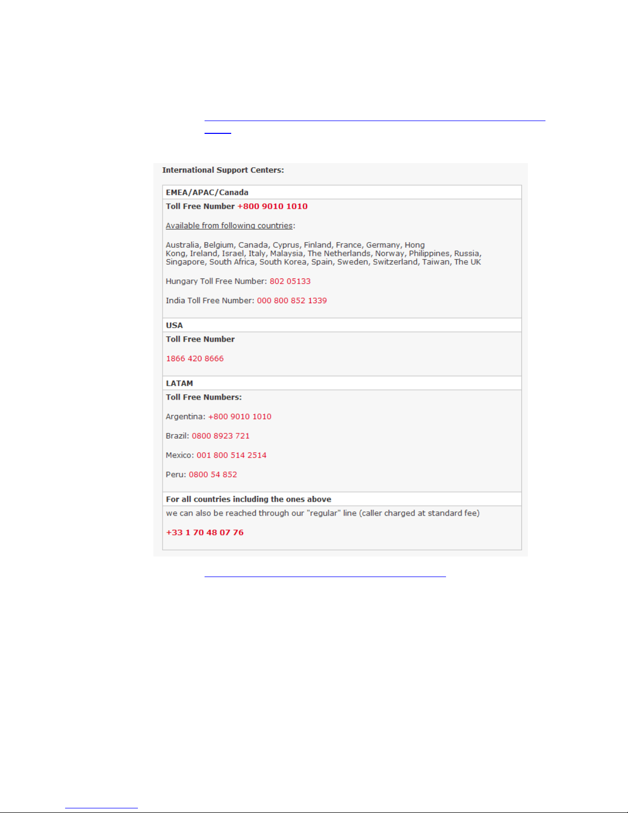
Contacting Thomson Video Networks Support Centers
http://www.thomson-networks.com/about-us/contact-us/technical-su
pport
Email: contact.support@thomson-networks.com
Page 4

4 ViBE EM4000
User Manual — 46073586AB02
BLANK PAGE
Page 5

Contents
ViBE EM4000 — Release 1.10 5
User Manual — 46073586AB02
Contents
Preface .............................................................. 1
Chapter
1
Overview ........................................................... 7
Product Overview .................................................................... 8
Purpose ......................................................................................... 8
Main Features............................................................................... 8
Encoder block diagrams ............................................................ 10
ViBE EM4000 NEM40IN2AA Encoder................................... 10
ViBE EM4000 NEM40IN4AA Encoder................................... 11
Encoder modes of operation..................................................... 11
Product Description............................................................... 13
Chassis ........................................................................................ 13
Overview ................................................................................ 13
Front Panel ............................................................................. 13
Rear Panel .............................................................................. 13
Chapter 2
Installation and Startup .................................. 15
Unpacking .............................................................................. 16
Installing the Device (Steps) ................................................. 17
Mounting in Rack................................................................... 18
ViBE EM4000 Installation Requirements.................................. 18
Ventilation................................................................................... 18
Cabling ........................................................................................ 23
EMC Ground ............................................................................... 23
Power Supply and Protective Ground...................................... 24
Power Supply Cord(s) Specifications................................... 24
Connecting AC Mains Power Supply Cord(s)................. 24
Power Supply End ........................................................24
ViBE EM4000 End .........................................................24
Powering Up .......................................................................... 25
Performing the Initial Settings.............................................. 26
Accessing the Local Console application................................. 26
Introduction............................................................................ 26
SSH client application setting............................................... 27
Accessing the Local Console ................................................ 27
Setting Initial Parameters .......................................................... 29
Commands Relating to IP Parameters................................. 29
Page 6

Contents
6 ViBE EM4000 — Release 1.10
User Manual — 46073586AB02
Displaying IP Parameters (ipdisp) ................................... 29
Editing IP parameters (ipset)............................................ 29
Commands Relating to the Date and Time ......................... 30
Displaying the current date and time (ddate)................. 30
Editing the date and time (sdate) .................................... 30
Commands relating to the NTP configuration .................... 31
Displaying NTP server status and IP address (dntp)...... 31
Editing NTP server status and IP address (sntp)............ 31
Declaring Web Interface Users............................................. 32
Foreword ........................................................................... 32
Adding a User (usradd) .................................................... 33
Deleting a User (usrdel).................................................... 33
Displaying the list of Users (usrlist) ................................ 34
Declaring Software options (if required)............................. 34
Connecting the Signal Cables.............................................. 35
On the rear panel ....................................................................... 35
Running the Web Browser................................................... 36
Chapter 3
Front Panel Operation ..................................... 37
Front Panel Description........................................................ 38
Foreword..................................................................................... 38
Description and overview.......................................................... 38
Setting LCD screen brightness and contrast............................ 40
Screen Description ............................................................... 41
Screen tree menu....................................................................... 41
Summary of screen functions................................................... 42
Device booting screen ............................................................... 42
Status screen .............................................................................. 43
Main Menu screen...................................................................... 43
Alarms screen............................................................................. 44
Setup screen............................................................................... 45
IP Settings screen .................................................................. 45
Recall screen .......................................................................... 46
Reboot screen ........................................................................ 48
LCD CAL screen ..................................................................... 48
Info screen .................................................................................. 49
Main Board Information screen.......................................... 49
Temperature Information screen ....................................... 50
Encoding Board Information screen .................................... 50
Chapter 4
Web Browser Interface .................................... 51
Encoder Web Interface Specifications ................................ 52
Protocol used.............................................................................. 52
Compatible Web Browsers........................................................ 52
Web Browser setting............................................................. 52
Page 7

Contents
ViBE EM4000 — Release 1.10 7
User Manual — 46073586AB02
Maximum number of connected Users.................................... 53
Definition of Encoder Users ...................................................... 54
Reaching the GUI................................................................... 55
Setting up the link between the PC and the Encoder.............. 55
Quick configuration ............................................................... 56
Screen Layout ........................................................................ 57
General information................................................................... 57
Status/Summary page ............................................................... 58
Status of the device............................................................... 60
Summary command .................................................................. 60
Alarms command....................................................................... 60
HW/SW information command................................................. 61
Settings .................................................................................. 63
Setting the ViBE EM4000 Encoder............................................ 63
Configuring the number of TSs at Encoder output ............ 63
Configuring LAN/WAN network interfaces.......................... 64
LAN/WAN network interface Eth1 ................................... 64
LAN/WAN network interface Eth2 ................................... 67
Configuring TS streams and IP encapsulation.................... 67
Configuring Expert Parameters............................................ 71
Setting a Basic encoder......................................................... 72
Basic encoder configuration ............................................ 72
Editing a service ...........................................................74
Editing an HD video component .................................75
Editing an Audio component ......................................83
Editing a VBI HD component .......................................96
Adding a PMT descriptor .............................................96
Editing Expert parameters ...........................................97
Predefined Configurations......................................................... 99
Overview of predefined configurations............................... 99
Displaying predefined configurations................................ 100
Configurations predefined in-factory (WBU_ISOG Conf). 100
WBU-ISOG configuration specifications....................... 101
Save / Recall Configurations............................................... 104
Saving the active configuration in the device ..........104
Recalling a configuration stored in the device ........105
Deleting a predefined configuration from the device 106
Saving a configuration file to disk ............................106
Loading a predefined configuration file from a disk 107
Maintenance......................................................................... 109
Rebooting the Encoder ............................................................ 109
Configuring the names of the Encoder and Basic encoders 110
Save / Load Encoder settings.................................................. 111
Saving Encoder settings to a disk ...................................... 111
Loading Encoder settings from a disk ............................... 112
Chapter 5
Servicing ....................................................... 115
Operations performed using the Local Console ............... 116
Page 8

Contents
8 ViBE EM4000 — Release 1.10
User Manual — 46073586AB02
Introduction .............................................................................. 116
Accessing the Local Console application............................... 116
IP parameter values on Encoder shipment ....................... 116
SSH client application setting ............................................ 116
Accessing the Local Console .............................................. 117
List of Local Console commands............................................ 117
Overview of commands...................................................... 118
Description of basic parameters ........................................ 120
Commands relating to IP parameters ........................... 120
Displaying IP parameters (ipdisp) .............................120
Editing IP parameters (ipset) .....................................121
Commands relating to the date and time..................... 121
Displaying the current date and time (ddate) ..........121
Editing the date and time (sdate) ..............................122
Commands relating to NTP configuration.................... 122
Displaying NTP server status and IP address (dntp) 122
Editing NTP server status and IP address (sntp) .....122
Commands relating to chassis topology ...................... 123
Displaying chassis topology (read) ...........................123
Displaying status, RID and Part Number (shelf) ......123
Managing software options .................................................... 124
Displaying software options (lsopt) ................................... 124
Ordering and installing software options.......................... 125
Ordering a software option (eqcod) (drid).................... 125
Installing a software option (insopt) ............................. 127
Uninstalling a software option (rmopt)......................... 128
Recovering lost keys....................................................... 129
Managing software licenses.................................................... 129
Software downloading ............................................................ 130
Managing Web Interface Users............................................... 130
Foreword .............................................................................. 130
Adding a User (usradd)....................................................... 132
Deleting a User (usrdel) ...................................................... 132
Displaying the list of Users (usrlist) ................................... 133
Managing predefined configurations..................................... 133
Foreword .............................................................................. 133
Saving a current configuration (pdcsave) ......................... 134
Loading a predefined configuration (pdcload) ................. 134
Deleting a predefined configuration (pdcrem).................. 135
Reading the description of a predefined configuration (pdcget)
136
Managing community strings and SNMP agent information 137
Foreword .............................................................................. 137
Reading SNMP agent information (rinfo).......................... 137
Writing SNMP agent information (winfo) ......................... 138
Displaying the list of community strings (cread).............. 138
Displaying the list of temporary community strings (clist) 139
Adding a community string (cadd) .................................... 140
Deleting a community string (cdel).................................... 140
Saving the list of community strings (csave).................... 140
Preventive and corrective maintenance operations ........ 142
Cleaning chassis ventilation grids .......................................... 142
Page 9

Contents
ViBE EM4000 — Release 1.10 9
User Manual — 46073586AB02
Replacing chassis fans............................................................. 142
Chapter 6
Tools ............................................................. 143
Download application ......................................................... 144
Overview................................................................................... 144
Operation .................................................................................. 144
Installing and running the application............................... 144
Installing the application ................................................ 144
Running the application ................................................. 146
Screen description............................................................... 147
Download procedure........................................................... 148
Uninstall an inactive software ............................................ 153
Other application commands ............................................. 155
Status messages.................................................................. 155
Error messages.................................................................... 156
Appendix A
Technical Specifications ............................... 159
General Device Specifications............................................ 160
Electrical Specifications........................................................... 160
Power supply ....................................................................... 160
Power Consumption............................................................ 160
Mechanical Features ................................................................ 161
Dimensions .......................................................................... 161
Weight .................................................................................. 162
Ventilation................................................................................. 162
Heat dissipating power............................................................ 162
Reliability .................................................................................. 163
Interface Specifications....................................................... 164
Input interfaces......................................................................... 164
Input Processing .................................................................. 164
Input formats................................................................... 164
Synchronizer.................................................................... 164
Video behavior ...........................................................164
Audio behavior ...........................................................165
VBI behavior ...............................................................165
Output interfaces...................................................................... 166
IP Adaptation........................................................................ 167
Ethernet interface............................................................ 167
Physical layer ..............................................................167
MAC Layer ..................................................................167
IP Layer ........................................................................167
Routing ........................................................................167
Mapping (encapsulation) ...........................................167
UDP mode (MPEG/UDP/IP) ........................................168
RTP mode (MPEG/RTP/UDP/IP) .................................168
Page 10

Contents
10 ViBE EM4000 — Release 1.10
User Manual — 46073586AB02
MPEG transmission ....................................................168
Control & Command interfaces .............................................. 169
Features ............................................................................... 170
MPEG system layer.................................................................. 170
HD Video encoding .................................................................. 171
Input HD video encoding formats ...................................... 171
HD Video preprocessing ..................................................... 171
HD Video processing........................................................... 173
Audio processing ..................................................................... 175
Test signals .......................................................................... 175
Audio capabilities ................................................................ 176
MPEG-1 Layer II audio encoding........................................ 177
Dolby Digital (AC3), Dolby Digital Plus (E-AC3) 2.0 encoding 177
Dolby Digital (AC3), Dolby Digital Plus (E-AC3) 5.1 encoding 177
AAC-LC, HE-AAC 2.0 encoding........................................... 177
AAC-LC, HE-AAC 5.1 encoding........................................... 177
Dolby® Digital (AC3) / Dolby® Digital Plus (E-AC3) Transport
(external encoding) ............................................................. 177
Audio description encoding ............................................... 178
Dolby E® decoding.............................................................. 179
Audio, other features .......................................................... 180
Audio silence alarms ...................................................... 180
Audio saturation alarms................................................. 180
Additional audio delay ................................................... 180
VBI Processing.......................................................................... 180
Time Code (VITC)................................................................. 180
Closed Caption..................................................................... 180
PVR descriptor ..................................................................... 180
Active Format Description (AFD)........................................ 181
HD Teletext........................................................................... 181
Flextream .................................................................................. 182
Control/Command.................................................................... 183
Control/Command via a Web Browser .............................. 183
Control/Command via the XMS ......................................... 183
Control/Command via SNMP ............................................. 183
NTP Time Synchronization ................................................. 183
Control/Command via the Encoder front panel ................ 183
Options ................................................................................ 185
Hardware options..................................................................... 185
Additional AC Power Supply .............................................. 185
Software options...................................................................... 185
Audio options ...................................................................... 185
MPEG-1 Layer II audio encoding ................................... 185
Dolby® Digital (AC3), Dolby® Digital Plus (E-AC3) 2.0 encoding
186
Dolby® Digital (AC3), Dolby® Digital Plus (E-AC3) 5.1 encoding
187
AAC-LC, HE-AAC, HE-AAC v2 2.0 encoding.................. 188
AAC-LC, HE-AAC 5.1 encoding ...................................... 189
Dolby® E decoding......................................................... 190
Dolby E monitoring ....................................................190
Dolby E® to PCM auto switch mode - Dolby Dual configura-
Page 11

Contents
ViBE EM4000 — Release 1.10 11
User Manual — 46073586AB02
tion ...............................................................................190
Dolby® E 5.1 to Dolby® E 2.0 auto switch mode - Dolby Dual
configuration ..............................................................191
Flextream options................................................................ 192
Local Flextream............................................................... 192
Remote Flextream........................................................... 192
Standard Compliance.......................................................... 193
Certifications and environmental specifications............... 194
EU declaration of conformity.............................................. 196
RoHS declaration of conformity......................................... 197
Ordering guide..................................................................... 198
Appendix B
Safety Instructions ........................................ 201
Safety Summary (English) ................................................. 202
Sicherheit - Überblick (Deutsch) ........................................ 206
Consignes de sécurité (Français) ....................................... 210
Safety Instructions for Finland, Norway, Sweden ........... 215
Appendix C
Regulatory Notices ........................................ 217
Appendix
D
Customer Services ........................................ 221
Support Center Contacts..................................................... 222
Warranty............................................................................... 224
Services ................................................................................ 225
Spare Parts........................................................................... 226
Returning Equipment .......................................................... 227
Repackaging for Shipment ................................................. 228
Long Term Product Support............................................... 229
Recycling the Product.......................................................... 230
Appendix E
Alarms ........................................................... 231
Glossary ........................................................ 233
Page 12

Contents
12 ViBE EM4000 — Release 1.10
User Manual — 46073586AB02
Index ............................................................. 249
Page 13

ViBE EM4000 — Release 1.10 1
User Manual — 46073586AB02
Preface
Standard Documentation Set
The standard ViBE EM4000 documentation set consists of:
a User Manual
a Quick Start Guide
The ViBE EM4000 User Manual contains background information about
the ViBE EM4000 Encoder, and describes operating procedures. This
manual can be used while learning about ViBE EM4000, and for
enhancing your basic knowledge of the product.
The ViBE EM4000 Quick Start Guide contains information about
installing and quickly configuring the equipment.
Software version
This manual covers the functionality of software Release 1.10 of the ViBE
EM4000 Encoder.
This manual continues to be relevant to subsequent software versions
where the functionality of the equipment has not changed. When a new
software version changes the functionality of the product, a new version
of this manual is provided.
About this Manual
This manual is written for Operators of the ViBE EM4000 Encoder.
The manual is organized into the following chapters and appendixes:
Chapter 1 ’
Overview
’ gives a general description of the equipment
and its main features. It also identifies the controls, indicators and
connectors on the front and rear panels.
This manual should be kept in a safe place for reference for the life
time of the equipment. If the equipment is passed on to a third party,
please ensure to pass on all relevant documentation including this
manual.
Page 14

Preface — Conventions Used in This Manual
2 ViBE EM4000 — Release 1.10
User Manual — 46073586AB02
Chapter 2 ’
Installation and setup
’ provides the procedures required
for device installation and initial configuration and describes how to
connect the device to other devices in your system.
Chapter 3 ’
Front Panel Operation
’ describes how to use the Front
Panel of the equipment.
Chapter 4 ’
Web Browser Interface
’ describes how to use the Web
Browser Graphical User Interface to configure the equipment.
Chapter 5 ’
Servicing
’ describes how to install software options via
the Command Line Interface and gives recommendations for cleaning
the air inlet grille.
Chapter 6 ’
Too ls
’ describes the tool(s) which can be used with the
product. In this release, the Download Application is described.
Appendix A ’
Technical Specifications
’ gives specifications of the
device, Device compliance, Declarations of Conformity and an
Ordering guide for ordering the device and its options.
Appendix B ’
Safety Instructions
’ gives instructions related to risk of
fire, electric shock or injury to persons.
Appendix C ’
Regulatory Notices
’ provides device compliances
regarding FCC emission control, Canadian EMC compliance, EN55022
Class A recommendations, VCCI Class A recommendations and Laser
compliance.
Appendix D ’
Customer Services
’ indicates what you should do if
you have a problem with equipment, whether you need to repair it, to
return it or to dispose of it.
Appendix E ’
Alarms
’ gives the list of alarms which may be visible in
the Alarm panel. For each alarm the diagnostics, action to be
performed and alarm severity are given.
A
glossary
can be found at the end of the manual just before the Index.
Conventions Used in This Manual
Warnings, Cautions and Notes
Heed Warnings
All warnings on the product and in the operating instructions should be
adhered to. The manufacturer cannot be held responsible for injuries or
damage where warnings and cautions have been ignored or taken
lightly.
Page 15
Preface — Conventions Used in This Manual
ViBE EM4000 — Release 1.10 3
User Manual — 46073586AB02
Read Instructions
All the safety and operating instructions should be read before this
product is operated.
Follow Instructions
All operating and use instructions should be followed.
Terms in this Manual
Safety-related statements appear in this manual in the following form:
Warning statements identify conditions or practices that may result
in personal injury or loss of life.
Caution statements identify conditions or practices that may result in
damage to equipment or other property, or which may cause
equipment crucial to your business environment to become
temporarily non-operational.
Notes provide supplementary information. They are highlighted for
emphasis, as in this example, and are placed immediately after the
relevant text.
Page 16

Preface — Documentation Feedback
4 ViBE EM4000 — Release 1.10
User Manual — 46073586AB02
Formatting
Naming conventions for the interface elements and Windows elements
in this manual follow the Microsoft Manual of Style, Third Edition.
Naming conventions for MPEG-2, ATSC, and DVB structures follow the
conventions derived from the standards documents listed in
Appendix A ’Technical Specifications’
. In addition, the following
formatting conventions apply to this manual:
Pale blue text refers to specific interface elements that you are
instructed to select, click, or clear.
Example: “Select Settings from the Configuration menu”.
Blue text refers to document names, sections, figures or tables.
Example: “Refer to Section ’Warnings, Cautions and Notes’ on page
13 for more information”.
Mono-spaced
text can indicate the following:
Text you enter from a keyboard
Example: “Enter
administrator
for your login and
administrator
for your password”.
Paths to components on your hard drive
Example: “The MIB is at the following location:
C:\MIB”.
Documentation Feedback
We take great care with our publications. Please help us to improve them
by sending your feedback with the reference of the manual to the email
address:
Email: techpubs@thomson-networks.com
Important notice
Thomson Video Networks reserves the right to make corrections,
modifications, enhancements, improvements and other changes to its
products or services at any time and to discontinue any product or
service without notice.
Page 17

Preface — Trademarks
ViBE EM4000 — Release 1.10 5
User Manual — 46073586AB02
Trademarks
Copyrights
© Copyright 2012 Thomson Video Networks. All rights reserved.
Dolby and the double-D symbol are registered
trademarks of Dolby laboratories.
Supply of this Implementation of Dolby technology
does not convey a license nor imply a right under any
patent, or any other industrial or intellectual property
right of Dolby Laboratories, to use this
Implementation in any finished end-user or
ready-to-use final product. It is hereby notified that a
license for such use is required from Dolby
Laboratories.
MPEG-2 / MPEG-4 AAC audio encoding technology is
authorized by the Fraunhofer IIS license
(
http://www.iis.fraunhofer.de/amm/
).
Thomson is a trademark of Technicolor S.A.
All other tradenames referenced are service marks, trademarks, or registered
trademarks of their respective companies.
Page 18

Preface — Copyrights
6 ViBE EM4000 — Release 1.10
User Manual — 46073586AB02
BLANK PAGE
Page 19

ViBE EM4000 — Release 1.10 7
User Manual — 46073586AB02
Chapter 1
Overview
Introduction
This chapter gives a general description of the equipment and its main
features. It also identifies the controls, indicators and connectors on the
front and rear panels.
In this Chapter
’Product Overview’
......................................................................page 8
’Product Description’
...................................................................page 13
Page 20
Chapter 1 ’Overview’ — Product Overview
8 ViBE EM4000 — Release 1.10
User Manual — 46073586AB02
Product Overview
Purpose
The ViBE EM4000 MPEG HD Encoder is a High Definition Video
Compression Encoder that provides real-time implementation of the
MPEG-4 AVC (H.264) compression algorithm for High Definition content
format.
The ViBE EM4000 provides video encoding of up to 4 video channels in
MP@L4 and HP@L4 formats at 2 to 20 Mbit/s.
The ViBE EM4000 MPEG Encoder features up to 4 HD-SDI inputs for up
to 4 HD video and embedded audio.
The compressed signals are available on 2 Giga Ethernet interfaces.
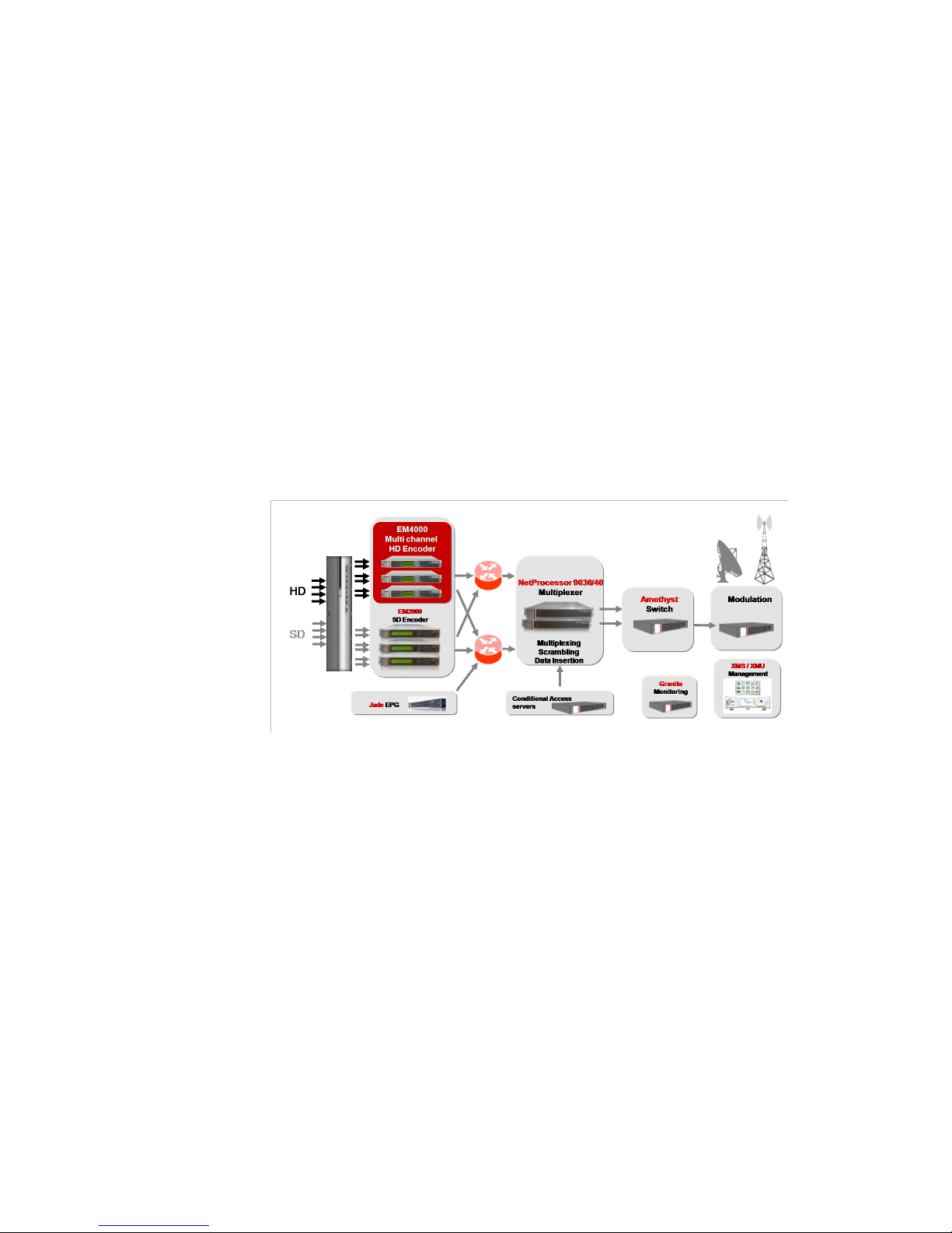
Figure 1-1. ViBE EM4000 in a Workflow
Main Features
(Some features are optional)
Inputs / Outputs
2 or 4 HD-SDI video inputs depending of the EM4000 version
2 GigE outputs
2 100/1000 BT Ethernet Control & Command links
Video
2 or 4 HD TV channels depending of the EM4000 version
Full MPEG-4 AVC support with MBAFF and PAFF for interlaced
contents
Remote Flextream (statistical multiplexing)
Capped VBR mode
Page 21

Chapter 1 ’Overview’ — Product Overview
ViBE EM4000 — Release 1.10 9
User Manual — 46073586AB02
Audio
HD-SDI embedded audio input
Audio transcoding
-
Dolby® E transcoding to Dolby® Digital (AC3) or Dolby
®
Digital Plus (E-AC3) stereo
-
Dolby® E transcoding to Dolby® Digital (AC3) 5.1 or Dolby
®
Digital Plus (E-AC3) 5.1
Audio encoding
-
MPEG-1 Layer II 2.0, 1.0
-
Dolby® Digital (AC3) 2.0, 1.0
-
Dolby® Digital (AC3) 5.1
-
Dolby® Digital Plus (E-AC3) 2.0, 1.0
-
Dolby® Digital Plus (E-AC3) 5.1
-
AAC-LC 2.0, 1.0
-
HE-AAC 2.0, 1.0
-
HE-AAC v2 2.0
-
AAC-LC 5.1
-
HE-AAC 5.1
Audio transport (external encoding)
-
Dolby® Digital (AC3)
-
Dolby® Digital Plus (E-AC3)
VBI processing
VITC
Closed Caption
PVR descriptor
WST (HD teletext)
AFD
Control and Monitoring
Control and Monitoring through Web Browser or XMS
eXtensible Management System
Monitoring through SNMP
Page 22

Chapter 1 ’Overview’ — Product Overview
10 ViBE EM4000 — Release 1.10
User Manual — 46073586AB02
Encoder block diagrams
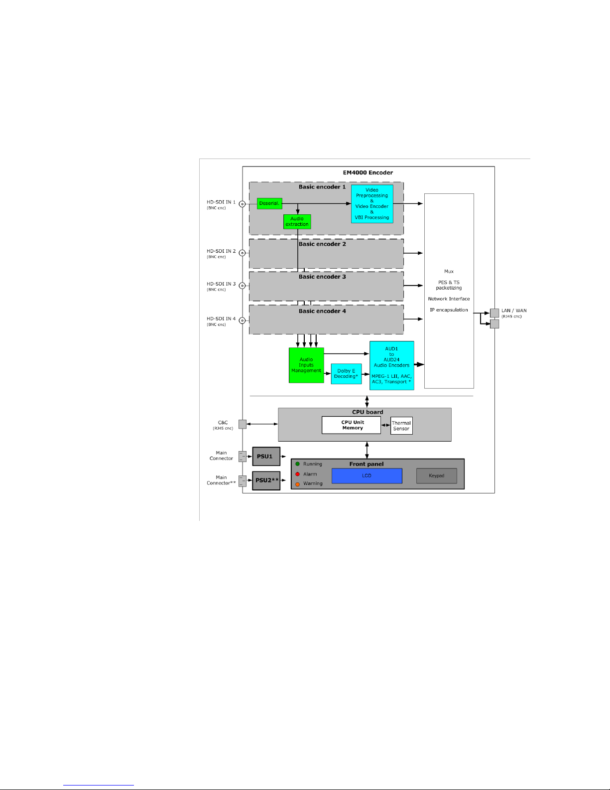
ViBE EM4000 NEM40IN2AA Encoder
The ViBE EM4000 NEM40IN2AA Encoder Block Diagram is represented
below:
Figure 1-2. ViBE EM4000 NEM40IN2AA block diagram
* Software options
** Hardware option
Page 23
Chapter 1 ’Overview’ — Product Overview
ViBE EM4000 — Release 1.10 11
User Manual — 46073586AB02
ViBE EM4000 NEM40IN4AA Encoder
The ViBE EM4000 NEM40IN4AA Encoder Block Diagram is represented
below:
Figure 1-3. ViBE EM4000 NEM40IN4AA block diagram
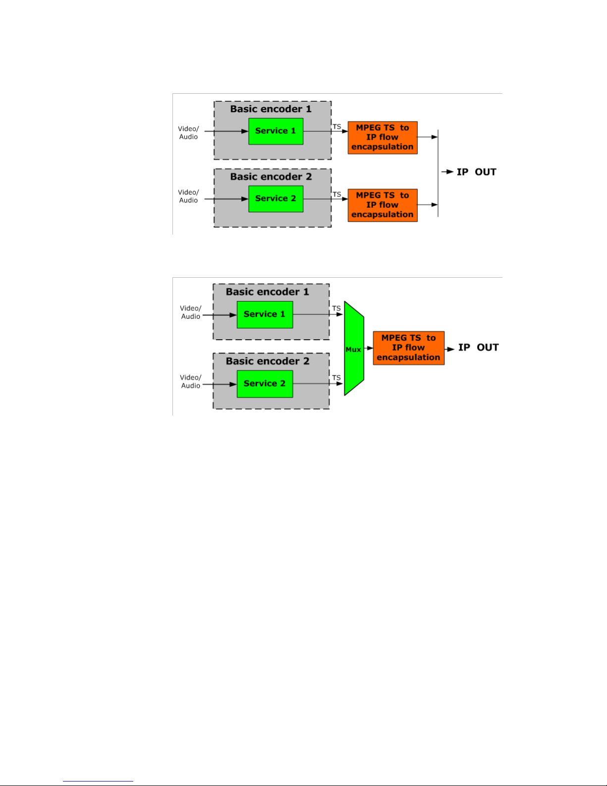
Encoder modes of operation
The ViBE EM4000 Encoder features some Basic encoders.
The device can be set to have:
1 MPTS at the output of each Basic encoder
1 MPTS at the output of the ViBE EM4000 Encoder
Some examples of these configurations are represented below:
* Software options
** Hardware option
Page 24
Chapter 1 ’Overview’ — Product Overview
12 ViBE EM4000 — Release 1.10
User Manual — 46073586AB02
Figure 1-4. 1 MPTS per channel (Basic encoder) operation mode - EM4000 NEM40IN2AA
Figure 1-5. 1 MPTS per shelf (ViBE EM4000 Encoder) operation mode- EM4000
NEM40IN2AA
Page 25
Chapter 1 ’Overview’ — Product Description
ViBE EM4000 — Release 1.10 13
User Manual — 46073586AB02
Product Description
Chassis
Overview
ViBE EM4000 is a modular product in a 1 RU 19” chassis with dual built-in
power supplies (a 2nd power supply can be supplied on an optional
basis).
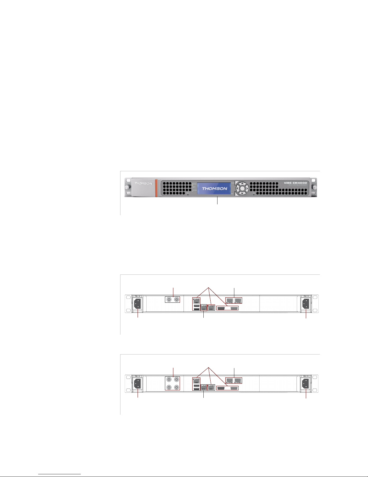
Front Panel
Figure 1-6. ViBE EM4000 front panel
The features of the ViBE EM4000 front panel are described in the Front
Panel Operation chapter of this User Manual.
Rear Panel
Figure 1-7. ViBE EM4000 NEM40IN2AA rear panel
Figure 1-8. ViBE EM4000 NEM40IN4AA rear panel
LEDs, LCD and keypad
IP Out
Mains connector
Input
Control In/Out
Mains connector Input
for the optional
AC Power Supply only
Reserved
SDI In
IP Out
Mains connector
Input
Control In/Out
Mains connector Input
for the optional
AC Power Supply only
Reserved
SDI In
Page 26

Chapter 1 ’Overview’ — Product Description
14 ViBE EM4000 — Release 1.10
User Manual — 46073586AB02
BLANK PAGE
Page 27

ViBE EM4000 — Release 1.10 15
User Manual — 46073586AB02
Chapter 2
Installation and Startup
Introduction
This chapter
provides the procedures required for device installation
and initial configuration and describes how to connect the device to
other devices in your system
.
In this Chapter
’Unpacking’
...................................................................................page 16
’Installing the Device (Steps)’
....................................................page 17
’Mounting in Rack’
.......................................................................page 18
’Powering Up’
...............................................................................page 25
’Performing the Initial Settings’
................................................page 26
’Connecting the Signal Cables’
.................................................page 35
Read and follow the important safety information in section
’Safety Instructions’ on page 201, noting especially those
instructions related to risk of fire, electric shock or injury to
persons.
Page 28

Chapter 2 ’Installation and Startup’ — Unpacking
16 ViBE EM4000 — Release 1.10
User Manual — 46073586AB02
Unpacking
Tab le 2 -1
lists the accessories that are always shipped with your device.
Use this list to ensure that your order is complete.
More accessories can be delivered depending on your chosen options.
Table 2-1. List of accessories delivered with the device
Quantity Description
1
ViBE EM4000 Encoder
1
ViBE EM4000 Quick Start Guide
1
CD-ROM
1
Acceptance Test Report
x
Power cables if ordered
Page 29

Chapter 2 ’Installation and Startup’ — Installing the Device (Steps)
ViBE EM4000 — Release 1.10 17
User Manual — 46073586AB02
Installing the Device (Steps)
The following steps are required for device installation and initial
configuration:
1.
Remove the protective film from both sides before installation.
2.
Mount the device in a rack.
3.
Power up the device.
4.
Enter the initial parameters via the Local Console application (IP
parameters, Date/Time, etc.).
5.
Connect the device to the other devices.
6.
Launch a Web Browser.
Page 30

Chapter 2 ’Installation and Startup’ — Mounting in Rack
18 ViBE EM4000 — Release 1.10
User Manual — 46073586AB02
Mounting in Rack
Rack mounting is not mandatory for ViBE EM4000 but the ventilation and
safety requirements given in this section must be observed in all cases.
ViBE EM4000 Installation Requirements
This section lists the principles to be observed and the steps to be taken
when installing ViBE EM4000 in a 19" rack.
Restrictions must be observed:
related to ventilation (see section
’Ventilation’
on page 18)
related to cabling (see section
’Cabling’ on page 23
)
related to EMC ground (see section
’EMC Ground’ on page 23
)
related to Power supply and protective ground (see section
’Power
Supply and Protective Ground’ on page 24
).
Ventilation
Please note that product failure rates are increased by high
temperatures. The following precautions should therefore be observed:
Prevent hot air from one device being introduced into other devices.
Ensure adequate distribution of air flows to the device intakes.
Avoid the effects of natural convection between devices.
Avoid hot/cold air short-circuits.
Avoid transverse effects in coupled racks.
Prevent hot air from accumulating in the rack.
Check the air flows: the rack should ensure a sufficient supply of cold
air and sufficient evacuation of hot air (according to the number of
devices mounted in the rack and their corresponding air flows).
The following important requirements should be noted in addition to the
general recommendations:
The chassis must not be fixed with its rack mounting ears only. If you
intend to install it in a rack, L-profiles are required and you must
observe the ventilation and safety instructions described in the
following sections.
Page 31

Chapter 2 ’Installation and Startup’ — Mounting in Rack
ViBE EM4000 — Release 1.10 19
User Manual — 46073586AB02
The device must be installed in a room with low dust levels. The
maximum density of dust in the air must not exceed 100μg/m
3
and the
maximum number of particles with a diameter greater than 1μm must
not exceed 1 million/m
3
. To prevent the power supply from
overheating, remember to regularly clean the rack filter (if there is
one) according to the manufacturer’s recommendations and clean
ViBE EM4000’s air inlet grill (at least once a year).
There must be enough room for a column of cold air to circulate on
the front of the chassis and a column of hot air to circulate on the rear
of the chassis.
Cut the L-profiles so as they do not exceed 4 mm in height in the areas
facing ViBE EM4000’s air outlet. This will prevent any hot air from
accumulating in the device.
Figure 2-1. L-profiles
Given its 1RU height, ViBE EM4000 can be placed on top of another
ViBE EM4000. It is however advisable to observe the following
restrictions:
It is possible to stack ViBE EM4000s in groups of two, each
group being separated from another group by a space of 1RU.
Failure to observe these installation requirements will directly
result in a deterioration in performance, reliability and service
life of equipment.
According to rack deph
4
Cut the L-profiles so as they do not exceed 4 mm in height in the areas facing ViBE EM4000’s air outlet.
Tapped hole (M4) for
EMC tape connecton
Air outlet
Page 32

Chapter 2 ’Installation and Startup’ — Mounting in Rack
20 ViBE EM4000 — Release 1.10
User Manual — 46073586AB02
Figure 2-2. First example: ViBE EM4000 on a pressurized floor in a standard rack (front
view)
FanFanFan
Pressurized floor
Hot air
Cold air
Fresh air supply for the units and racks: 18°C @50-60% relative humidity
Page 33

Chapter 2 ’Installation and Startup’ — Mounting in Rack
ViBE EM4000 — Release 1.10 21
User Manual — 46073586AB02
Figure 2-3. Second example:ViBE EM4000 on an unpressurized floor in a standard rack
(front view)
Fresh air supply for the units and racks: 18°C @50-60% relative humidity
FanFanFan
Unpressurized floor
Hot air
Cold air
Page 34

Chapter 2 ’Installation and Startup’ — Mounting in Rack
22 ViBE EM4000 — Release 1.10
User Manual — 46073586AB02
Figure 2-4. ViBE EM4000 in a standard rack (side view)
Note: The 1RU side blank panel and pre-cut L-profiles can be replaced by an inverted L-profile
RIGHT SIDE
L-profile
RACK
REAR
RACK
FRONT
1 RU
1 RU SIDE BLANK PANEL
1 RU SIDE BLANK PANEL
1 RU SIDE BLANK PANEL
1 RU SIDE BLANK PANEL
1 RU SIDE BLANK PANEL
1 RU SIDE BLANK PANEL
1 RU SIDE BLANK PANEL
1 RU SIDE BLANK PANEL
1 RU SIDE BLANK PANEL
RACK
FRONT
1 RU SIDE BLANK PANEL
1 RU SIDE BLANK PANEL
1 RU SIDE BLANK PANEL
1 RU SIDE BLANK PANEL
1 RU SIDE BLANK PANEL
1 RU SIDE BLANK PANEL
1 RU SIDE BLANK PANEL
1 RU SIDE BLANK PANEL
1 RU SIDE BLANK PANEL
MIN: 800mm
MIN: 800mm
635mm
635mm
LEFT SIDE
Page 35

Chapter 2 ’Installation and Startup’ — Mounting in Rack
ViBE EM4000 — Release 1.10 23
User Manual — 46073586AB02
Cabling
It is essential to separate the power supply cables from the signal cables.
When facing the rear of the rack (as the device is connected via the rear
panel), the power supply cables must be guided to the right of the chassis
and the signal cables to the left.
EMC Ground
The EMC connection is required to ensure ground equipotentiality
between the different devices in the technical center (only one
connection is required per device).
Each Encoder side panel features a tapped hole to connect a bonding
strip. The bonding strip can be fixed either on one side of the chassis
(right or left side) or on the rear of the chassis (left side).
Fixing the bonding strip on the back of the chassis. The bonding strip
is fixed using an M4 nut (provided with the product). It must have a
6mm² cross-section and be under 500mm in length.
Fixing the bonding strip on the side of the chassis. The bonding strip
is fixed using an M4 screw whose length depends on the bonding strip
type (no more than 15 mm of the screw must be inserted into the
Encoder). The bonding strip must have a 6 mm² cross-section and be
under 500 mm in length.
The rack EMC DC bus (to which the ViBE EM4000 EMC strip is connected)
must be connected to the rack ground pin. This pin is also connected to
the safety ground.
Figure 2-5. EMC screw, rear panel
PSU 1 N
EMC screw (M4) Tapped hole (M4)
Page 36

Chapter 2 ’Installation and Startup’ — Mounting in Rack
24 ViBE EM4000 — Release 1.10
User Manual — 46073586AB02
Power Supply and Protective Ground
Power Supply Cord(s) Specifications
The AC mains power cords are only shipped with the device if ordered.
Otherwise, it is advisable to use mains cables with the following features:
Device end of cable: IEC 320 compliant connector
Flexible wire: 3 x 1 mm2 cross-section or 18 AWG, 10 A minimum,
250 V compliant with the applicable standard or rules of the country
where the device is installed
Mains outlet end of cable: plug compliant with the applicable standard
or rules of the country where the device is installed.
Connecting AC Mains Power Supply Cord(s)
Power Supply End
The connection panel should comply with the legislation in force in the
country of installation. The connection panel must be positioned in the
rack in such a way that the plug and power cord(s) are within easy reach
for switching off purposes.
For (each) mains inlet, the wiring system must feature overload and earth
fault protection and a bipolar cut-off device or a differential circuit
breaker. If in doubt, contact a qualified electrician.
ViBE EM4000 End
Plug the power cord(s) into the mains inlet(s).
Page 37

Chapter 2 ’Installation and Startup’ — Powering Up
ViBE EM4000 — Release 1.10 25
User Manual — 46073586AB02
Powering Up
Connect the power cords. The green Power LED(s) PSU 1 (and PSU 2 if
optional PSU is installed) will come on.
After a start-up phase, the device will become operational. When the
device is switched on, the last stored configuration will be active.
Check that ViBE EM4000 is not yet connected to the LAN as
factory-set IP addresses may cause disturbance on the LAN when
ViBE EM4000 is switched on (address conflict).
Page 38

Chapter 2 ’Installation and Startup’ — Performing the Initial Settings
26 ViBE EM4000 — Release 1.10
User Manual — 46073586AB02
Performing the Initial Settings
Accessing the Local Console application
Introduction
The device features the Local Console application. The Local Console
application can be accessed by connecting to the Encoder via the
CONTROL 1 Ethernet link and an SSH client application.
The free PuTTY SSH client application is used in this chapter.
The PuTTY application can be downloaded on
http://www.putty.org/
Figure 2-6. PuTTY application
Page 39

Chapter 2 ’Installation and Startup’ — Performing the Initial Settings
ViBE EM4000 — Release 1.10 27
User Manual — 46073586AB02
Figure 2-7. Control 1 connector, ViBE EM4000 NEM40IN2AA rear panel
As the ViBE EM4000 Control Ethernet interfaces host an autocrossover
mechanism, you can use a direct or crossed cable connection between
the PC and ViBE EM4000.
SSH client application setting
The SSH client application must be set with the following parameters:
Host name (or IP address):
Encoder IP address
Port:
22
Accessing the Local Console
1.
Run the SSH application on the PC connected to the network using the
Encoder IP address. The Login page is displayed.
2.
Enter
user
as Login
Figure 2-8. Enter login, Login page
3.
Enter
user
as password
The Local console main screen is displayed:
The ViBE EM4000 IP address, which is required for the
first
connection, is given on the
Acceptance Test Report
shipped
with the device.
The factory set IP address and Netmask for the Control &
Command port are 192.168.1.1 and 255.255.255.0.
The Encoder IP address can be viewed/edited via the Encoder
Front panel. Refer to section
’IP Settings screen’
on page 45.
The IP address can be changed during the installation setup (see
section
’Editing IP parameters (ipset)’
on page 29) or via the
Encoder Front panel. Refer to section
’IP Settings screen’
on
page 45.
This IP address will be the new customer set IP address that will
be required for subsequent connections to the device.
Control 1
Page 40

Chapter 2 ’Installation and Startup’ — Performing the Initial Settings
28 ViBE EM4000 — Release 1.10
User Manual — 46073586AB02
Figure 2-9. Local Console main screen
Page 41

Chapter 2 ’Installation and Startup’ — Performing the Initial Settings
ViBE EM4000 — Release 1.10 29
User Manual — 46073586AB02
Setting Initial Parameters
Commands Relating to IP Parameters
The following procedure is used to set the IP parameters of the Control 1
& 2 port located on the ViBE EM4000’s rear panel.
Displaying IP Parameters (ipdisp)
To display the Encoder IP parameters, type
ipdisp
after the
ViBE
prompt:
Figure 2-10. Displaying Encoder IP parameters - ipdisp command
Editing IP parameters (ipset)
To edit the Encoder IP parameters, type
ipset
after the
ViBE
prompt:
Figure 2-11. Editing Encoder IP parameters - ipset command
Enter the new value of the parameter(s) to be edited and press
Return
.
If the parameter does not require editing, you do not need to enter its
value. Just press
Return
straight after ? to confirm the current value.
If the IP gateway address is not used, type
0.0.0.0
.
Type y after Sure to modify ? if you wish to confirm the new
configuration or
n
if you wish to keep the previous configuration.
The changes will be acknowledged after the Encoder has been
rebooted.
The Encoder must be connected to the network during the boot
which follows IP address configuration to facilitate detection of
MAC/IP address pair changes.
Page 42

Chapter 2 ’Installation and Startup’ — Performing the Initial Settings
30 ViBE EM4000 — Release 1.10
User Manual — 46073586AB02
Commands Relating to the Date and Time
Displaying the current date and time (ddate)
To display the current date and time, type
ddate
after the
ViBE
prompt:
Figure 2-12. Displaying the current date and time - ddate command
UTC date and time will be displayed.
Editing the date and time (sdate)
To edit the date and time, type
sdate after the ViBE
prompt:
Figure 2-13. Editing the date and time - sdate command
Enter the following fields:
Type the new date and time values in month, day, hour, minute and
year format (without spaces) after UTC time ?.
Typey
after Apply date&time now ? if you wish to confirm the new
values or
n
if you wish to keep the previous values.
The
Done
message will be displayed to indicate that the changes have
been acknowledged.
Page 43

Chapter 2 ’Installation and Startup’ — Performing the Initial Settings
ViBE EM4000 — Release 1.10 31
User Manual — 46073586AB02
Commands relating to the NTP configuration
The purpose of NTP (Network Time Protocol) is to synchronize devices
via a shared network. An external NTP server serves as reference for the
Encoder, which is an NTP client (its internal clock is synchronized with the
NTP server).
Displaying NTP server status and IP address (dntp)
To display the NTP server status and IP address, type
dntp
after the
ViBE
prompt:
Figure 2-14. Displaying NTP server status and IP address - dntp command
Editing NTP server status and IP address (sntp)
To edit the NTP server status and IP address, type
sntp
after the
ViBE
prompt:
Figure 2-15. Editing NTP server status and IP address - sntp command
To enable/disable time synchronization, type 1 (Enable) or 0
(Disable).
To edit the preferred IP address, type the new address on the second
line.
You are advised to manually set the ViBE EM4000 system clock as
close as possible to the NTP server clock. Several minutes are
required to achieve perfect synchronization between the two
platforms.
The changes will be acknowledged after the Encoder has been
rebooted.
The first synchronization operation may take up to 20 minutes.
Page 44

Chapter 2 ’Installation and Startup’ — Performing the Initial Settings
32 ViBE EM4000 — Release 1.10
User Manual — 46073586AB02
Declaring Web Interface Users
Foreword
The Encoder can be operated via a Web Browser connected to the Web
Interface featured on the device. Users accessing the Encoder via this
Interface must have been declared in the device. User declaration and
management (creation, deletion, password, rights, etc.) are performed
via the Local Console.
User rights are defined according to four preset profiles: Operator,
Technician, Administrator, Service. The rights corresponding to the
profiles are as follows:
The following Users are defined on device shipment:
Table 2-2. Web Interface User Profiles and corresponding rights
operator technician administrator service
View Topology
XX XX
View Predefined
Configurations
XX XX
Create Predefined
Configurations
XXX
Recall Predefined
Configurations
XXX
View Encoder
Configuration
XX XX
Edit Encoder
Configuration
XXX
View Alarms
XX XX
Reboot Device
XXX
Create User
XX
Table 2-3. Users defined on device shipment
User name Password Profile
admin
admin administrator
service
service service
technician
technician technician
operator
operator operator
user
user operator
Page 45

Chapter 2 ’Installation and Startup’ — Performing the Initial Settings
ViBE EM4000 — Release 1.10 33
User Manual — 46073586AB02
It is possible to edit the characteristics of these Users and a maximum of
64 Users can be defined.
Adding a User (usradd)
To add a User, type
usradd
after the
ViBE
prompt:
Figure 2-16. Adding a Web Interface User - usradd command
Enter the following fields:
name: User name
password: password for accessing the Web Interface
confirm password: re-enter the password for accessing the Web
Interface
profile: enter the User profile. The available profiles are given just
above this field.
The following information will be displayed:
add xxxxxx as yyyyyyy: User xxxxxx with the profile yyyyyyy has
been successfully added.
If the operation is not successful, the reason for failure will be
displayed.
Deleting a User (usrdel)
To delete a User, type
usrdel after the
ViBE
prompt:
guest
guest guest (=operator)
Table 2-3. Users defined on device shipment
User name Password Profile
Page 46

Chapter 2 ’Installation and Startup’ — Performing the Initial Settings
34 ViBE EM4000 — Release 1.10
User Manual — 46073586AB02
Figure 2-17. Deleting a Web Interface User - usrdel command
Enter the following fields:
name: name of User to be deleted
The following information will be displayed:
remove xxxxx
: User xxxxx has been successfully deleted.
If the operation is not successful, the reason for failure will be displayed.
Displaying the list of Users (usrlist)
To display the list of Users and their profiles, type
usrlist
after the
ViBE
prompt:
Figure 2-18. Displaying the list of Web Interface Users - usrlist command
The following information will be displayed:
User
: User name
Profile
: User profile
Declaring Software options (if required)
If software options need to be installed, see the
Servicing
chapter to
install them using the Local Console.
If options are ordered with the product, they will have been installed
at the factory and will be immediately available to the operator.
Page 47

Chapter 2 ’Installation and Startup’ — Connecting the Signal Cables
ViBE EM4000 — Release 1.10 35
User Manual — 46073586AB02
Connecting the Signal Cables
On the rear panel
Figure 2-19. Rear Panel, ViBE EM4000 Encoder
Connect the CONTROL 1 Ethernet
link used to operate the device
Not Used
Connect the IP 1 & IP 2 output(s) to the downstream
device(s)
Not Used
Connect the SDI In
to the video
sources
Optional
Note: Rear Panel depends on the Encoder type and Hardware option installed
Page 48

Chapter 2 ’Installation and Startup’ — Running the Web Browser
36 ViBE EM4000 — Release 1.10
User Manual — 46073586AB02
Running the Web Browser
When the previous installation procedure is complete, device operation
can begin. Set up the connection between the PC and the Encoder. To do
this:
1.
Run the Web Browser on the PC connected to the Encoder via the
Control Ethernet link.
2.
Connect to the Encoder by entering its IP address. The Login page will
be displayed:
Figure 2-20. Login page
3.
Log in by entering your
Username
and
Password (admin
can be
entered for both the default username and password if it has not been
deleted from the list of Users). The device Status/Summary page will
be displayed:
Figure 2-21. Status/Summary page
To operate the Encoder via its Web Browser Interface, refer to
Chapter 4
’Web Browser Interface’
on page 51
.
Page 49

ViBE EM4000 — Release 1.10 37
User Manual — 46073586AB02
Chapter 3
Front Panel Operation
Introduction
This chapter explains how to use the Front Panel to configure the
equipment.
In this Chapter
’Front Panel Description’
............................................................page 38
’Screen Description’
....................................................................page 41
Page 50

Chapter 3 ’Front Panel Operation’ — Front Panel Description
38 ViBE EM4000 — Release 1.10
User Manual — 46073586AB02
Front Panel Description
Foreword
The aim of the front panel is not to replace the Management System but
to provide a basic control/command interface for the main settings.
Device operation via its front panel is generally limited to:
changing basic settings (IP settings, etc.).
displaying device codes and serial numbers.
displaying installed software releases.
displaying raised alarms.
recalling predefined configurations. These configurations are defined
via the Web Interface or in-factory. For more information, see section
’Web Browser Interface’
on page 51.
displaying device internal temperature.
rebooting the device.
Description and overview
The Encoder front panel features an LCD screen, a 7-key keypad (Home,
ESC, OK and 4 arrow keys) and a set of three status LEDs and 2 Power
Supply LEDs.
Figure 3-1. ViBE EM4000 - Front Panel
Device status LEDs
They indicate the following:
Table 3-1. Device status LED specifications
LED Color Description
RUNNING
green The Device is On
ALARM
red At least one major alarm has been raised
WARNING
orange At least one minor alarm has been raised
OK
LEFT
HOME
PSU 2
ESC DOWN
UP
Running
Warnin g
PSU 1
Alarm
RIGHT
Page 51

Chapter 3 ’Front Panel Operation’ — Front Panel Description
ViBE EM4000 — Release 1.10 39
User Manual — 46073586AB02
Power Supply LEDs
They indicate the following:
Keypad
The keypad features 7 keys used to display and select a menu or a
setting:
To change a numeric value with the keypad:
1.
Select the value to change using the Í or Î key until the marker
indicates the value to change.
2.
Set the value with the Ï or Ð key.
3.
Press the OK key to confirm the new value.
LCD screen
The LCD screen features a graphic display (192 x 64 pixels). It provides up
to 4 lines:
Line 1: menu context
Lines 2, 3 and 4: 2 x 3 menu matrix
Table 3-2. Power Supply LED specifications
LED Description
PSU 1
Power Supply No. 1 is On
PSU 2
Power Supply No. 2 (optional PSU) is On
Table 3-3. Keypad specifications
Key Function
Î
Move the cursor to the right
Í
Move the cursor to the left
Ï
Move the cursor up
Ð
Move the cursor down
OK
Access the main menu, a sub-menu or confirm a setting value
ESC
Go back to the menu above
HOME
Go back to the MAIN menu
Page 52

Chapter 3 ’Front Panel Operation’ — Front Panel Description
40 ViBE EM4000 — Release 1.10
User Manual — 46073586AB02
Figure 3-2. LCD menu matrix overview
Symbols (or markers) help to locate and/or select displayed items:
Setting LCD screen brightness and contrast
For optimum readability of texts displayed on the LCD screen, it may be
necessary to adjust the Brightness and Contrast according to the lighting
conditions. Refer to section
’LCD CAL screen’
on page 48.
MENU CONTEXT
<ITEM1> <ITEM2>
<ITEM3> <ITEM4>
<ITEM5> <ITEM6>
Table 3-4. Meaning of Encoder front panel LCD symbols
Symbol Meaning
< Animated symbol, in the top right of the status screen,
indicating that the Encoder is operational.
>
<
Text preselection marker. The selected text can then be
confirmed by pressing the OK key on the keypad. Move this
marker using one of the 4 arrow keys.
Page 53

Chapter 3 ’Front Panel Operation’ — Screen Description
ViBE EM4000 — Release 1.10 41
User Manual — 46073586AB02
Screen Description
Screen tree menu
Figure 3-3. Menu tree of screens displayed on the Encoder front paneI
Page 54

Chapter 3 ’Front Panel Operation’ — Screen Description
42 ViBE EM4000 — Release 1.10
User Manual — 46073586AB02
Summary of screen functions
List summarizing the functions that can be accessed via the screens:
Device booting screen
When the device is powered on, after a few seconds the LCD lights on
and the following message is displayed during the booting process:
Table 3-5. Functions that can be accessed via the Encoder front panel screens
Screen Function
section
’Device booting screen’
on page 42 Indicates that the device is starting
up.
section
’Status screen’
on page 43 Indicates the device name and IP
address.
section
’Main Menu screen’
on page 43 Displays available sub-menus.
section
’Alarms screen’
on page 44 Displays alarms raised on the
device.
section
’Setup screen’
on page 45 Displays available sub-menus.
section
’IP Settings screen’
on page 45
Displays and used to edit device IP
settings.
section
’Recall screen’
on page 46
Used to recall a predefined
configuration.
section
’Reboot screen’
on page 48
Used to reboot the device.
section
’LCD CAL screen’
on page 48
Used to adjust the LCD brightness
and contrast.
section
’Info screen’
on page 49 Displays available sub-menus.
section
’ Main Board Information
screen’
on page 49
Displays Main board information.
section
’ Temperature Information
screen’
on page 50
Displays Temperature information.
section
’Encoding Board Information
screen’
on page 50
Displays Encoder board(s)
information.
Page 55

Chapter 3 ’Front Panel Operation’ — Screen Description
ViBE EM4000 — Release 1.10 43
User Manual — 46073586AB02
Figure 3-4. Booting screen
The Status screen will be displayed once the booting process is
complete:
Figure 3-5. Status screen
The Status screen is described below.
Status screen
Figure 3-6. Status screen
Main Menu screen
To display the Main Menu screen:
From the Status screen, press the OK key.
From a sub-menu, press the ESC key once or more depending on the
sub-menu displayed.
ViBE Launching ...
ViBE EM4000 STATUS <
EM400x: XXXXXXXX
IP Address: 10.12.54.24
ViBE EM4000 STATUS <
EM400x: XXXXXXXX
IP Address: 10.12.54.24
< Animated symbol, used to indicate that the Encoder is
operational.
EM400x Indicates the name of the Encoder. This name is
assigned via the Management System (Web Browser or
XMS).
IP Address Indicates the Encoder IP address.
Page 56

Chapter 3 ’Front Panel Operation’ — Screen Description
44 ViBE EM4000 — Release 1.10
User Manual — 46073586AB02
Figure 3-7. Main Menu screen
To select a sub-menu, use the Í, Î, Ð and Ï
keys and then confirm your
choice by pressing the OK
key.
Available sub-menus:
Alarms screen
The Alarms screen is used to view alarms raised on the device. To display
this screen, go to the Main menu screen, select ALARMS
using the arrow
keys and press OK.
Figure 3-8. Alarms Menu screen
MAIN
<ALARMS> SETUP
INFO
Alarms Used to display alarms raised on the Encoder.
Setup Used to:
Set device IP settings
Recall a predefined configuration
Reboot the device
LCD adjustments (Contrast and Brightness)
Info Used to get information about Encoder board
references, chassis references, serial numbers, release
numbers and temperatures.
ALARMS Severity
ÏÐ
Name XX/YY
[AID/AID ext] : Alarm Wording (first line)
Alarm Wording (last line)
Severity Used to indicate alarm severity. The alarm can be
Critical, Major, Minor or Warning
.
Name Used to indicate the name of the function with the
alarm(s): MAIN Brd, ENCODER 1 Brd, ENCODER 2 Brd,
etc.
XX/YY
XX
indicates the number of the alarm in the YY list,
where
YY
represents the total number of alarms raised.
Page 57

Chapter 3 ’Front Panel Operation’ — Screen Description
ViBE EM4000 — Release 1.10 45
User Manual — 46073586AB02
If necessary, the Ð and Ï
keys can be used to display the next or
previous alarm.
Setup screen
The Setup screen is used to access the IP Settings, Recall, Reboot and
LCD CALibration sub-menus. To display this screen, go to the Main menu
screen, select
SETUP using the arrow keys and press OK.
Figure 3-9. Setup screen
IP Settings screen
The IP Setting screen is used to view and set the Control & Command IP
Settings. To display this screen, go to the Setup screen, select
IP
SETTING
using the Í and Î keys and press OK.
The IP Address, Netmask and Gateway will be displayed:
Figure 3-10. IP Settings screen
Example: Procedure for editing the IP Address (the procedure is the
same to edit the IP Netmask or IP Gateway values)
Use the Ð and Ï
keys to select Address, Netmask or Gateway
setting and press OK. The first digit is blinking.
AID/AID ext Used to indicate the alarm identifiers (Alarm ID and
Alarm ID Extension) so that it is easier to find relevant
information in the documentation.
Alarm Wording Used to provide the alarm description, which is
identical to the description displayed on the
Management System.
The list of alarms is created when the Alarms screen is selected. To
update the list of alarms, you will need to exit the Alarms
screen.
SETUP
<IP SETTING> RECALL
REBOOT LCD CAL
IP SETTING
<IP Address> : 10.141.247.40
IP Netmask : 255.255.255.0
IP Gateway : 10.141.127.40
Page 58

Chapter 3 ’Front Panel Operation’ — Screen Description
46 ViBE EM4000 — Release 1.10
User Manual — 46073586AB02
Use the Í and Î keys to select the field to be modified and then
use the
Ð
and Ï
keys to adjust the value. Refer to figure below:
Figure 3-11. IP Address, Settings screen
Confirm the new value by pressing OK. The Confirm screen will
be displayed:
Figure 3-12. IP Address settings, Confirm screen
Press OK to enable the new IP address or press ESC/HOME to
exit this screen.
Recall screen
The Recall screen is used to recall a predefined configuration.
Configurations are predefined via the Web Interface. To define
configurations, see section
’Predefined Configurations’
on page 99. To
display the Recall screen, go to the Setup screen, select
RECALL
using
the
Í
and Î
keys and press OK.
Figure 3-13. Recall screen
IP Address
010 141.127.040
011 141.127.040
IP Address :11.141.127.40
Do you Confirm update
No=ESC Yes=OK
The consistency between the IP address and Gateway address is
checked. If an error is detected a Bad value message can be
displayed. The Gateway address can also be resetted.
The changes will be acknowledged after the Encoder has been
rebooted.
RECALL XX/YY
ÏÐ
ZZ EQU: -----------------> ZZ EQU: ------------------
ZZ ENC: -----------------ZZ ENC: ------------------
XX/YY
XX
indicates the number of the currently selected
predefined configuration.
YY
indicates the total number
of predefined configurations.
Page 59

Chapter 3 ’Front Panel Operation’ — Screen Description
ViBE EM4000 — Release 1.10 47
User Manual — 46073586AB02
Procedure for recalling a configuration
Select the configuration to be recalled on the Recall screen using
the
Ð
or Ï keys.
Confirm your choice by pressing OK.
If the recalled configuration is a Basic encoder type
configuration, the following screen will be displayed:
Figure 3-14. Recall, Basic encoder type configuration screen
Select the Basic encoder (ENCx) to be configured using the Ð or
Ï
keys.
Confirm your choice by pressing OK.
Regardless of the type of recalled configuration, the Confirm
screen will be displayed:
Figure 3-15. Recall, Confirm screen
Press OK to enable the recall or ESC/HOME to exit this screen.
At the end of the operation and if the recall was successful, the
following screen will be displayed:
Figure 3-16. Recall, recall successful screen
An error message will be displayed in the event of failure.
ZZ EQU: ........
ZZ
: Used to indicate the ID of the configuration.
EQU
(or
ENC
): Used to indicate the type of
configuration
(EQU =chassis,ENC = Basic encoder).
-------:
Name of the configuration as set on creation.
RECALL Preset ZZ ENC1
Select Target Id: 1
Use Up/Down, then OK
RECALL Preset ZZ XXX
Do you Confirm Recall?
No=ESC Yes=OK
RECALL Preset ZZ XXX
Recall Done, Press OK
Page 60

Chapter 3 ’Front Panel Operation’ — Screen Description
48 ViBE EM4000 — Release 1.10
User Manual — 46073586AB02
Reboot screen
The Reboot screen is used to reboot the device. To display this screen, go
to the Setup
screen, select
REBOOT using the Í and Î
keys and press
OK.
Figure 3-17. Reboot screen
Procedure for rebooting the device
Press OK to reboot the device. If you do not wish to reboot the device,
press ESC/HOME to exit this screen.
LCD CAL screen
The LCD Calibration screen is used to adjust the LCD Brightness and
Contrast. To display this screen, go to the Setup
screen, select
LCD CAL
using the Í and Î
keys and press OK.
Figure 3-18. LCD CAL screen
Procedure for adjusting LCD Brightness or Contrast
Use the
Í
and Î
keys to select the Brightness or Contrast setting and
press OK
.
Figure 3-19. Brightness CAL screen
Use the Ð and Ï
keys to adjust the setting according to the lighting
conditions.
REBOOT
Reboot Equipment?
No=ESC Yes=OK
LCD CAL.
<BRIGHTNESS> CONTRAST
BRIGHTNESS
Adjust Brightness = Up/Down
Save=OK Exit=Esc/Home
Page 61

Chapter 3 ’Front Panel Operation’ — Screen Description
ViBE EM4000 — Release 1.10 49
User Manual — 46073586AB02
Press OK to confirm and save the setting(s) or ESC/HOME to exit this
screen without saving the setting(s). If OK is pressed the new settings
will be restored on next Encoder power up, otherwise the previous
settings will be recalled.
Info screen
The Info screen is used to access the Main Board or Encoding Board(s)
information sub-menu. To display this screen, go to the Main menu
screen, select
Info
using the Í and Î
keys and press OK.
Figure 3-20. Info screen
Main Board Information screen
The Main Board Information screen is used to get Main Board
information. To display this screen, go to the Info screen, select
MAIN
using the Í and Î
keys and press OK.
The following information will be displayed:
Figure 3-21. Main Board Info screen
INFO
<MAIN> TEMPER.
ENC. 1/2 ENC. 2/2
MAIN BOARD INFO
Active SW :EM4000 XX.XXXX
HW Version :NEM40IN2
EQCODE : XXXX
S/N :sn XXXXXXXX
Active SW Used to indicate the Main board active Software release
number.
HW Version Used to indicate the Main board Hardware release
number.
EQCODE Used to indicate the Main board equipment code. The
equipment code is used to order a software option.
S/N Used to indicate the Main board serial number.
Page 62

Chapter 3 ’Front Panel Operation’ — Screen Description
50 ViBE EM4000 — Release 1.10
User Manual — 46073586AB02
Temperature Information screen
The Temperature Information screen is used to display the Ambient
Temperature. To display this screen, go to the Info screen, select
TEMPER.
using the Í and Î
keys and press OK.
The following information will be displayed:
Figure 3-22. Temperature Info screen
Encoding Board Information screen
The Encoding Board Information screen is used to get Encoding Board(s)
information. The ViBE EM4000 2 video channels features one Encoding
board, The ViBE EM4000 4 video channels features two Encoding boards.
To display this screen, go to the Info screen, select
Encoding
using the
Í
and Î
keys and press OK.
The following information will be displayed:
Figure 3-23. Encoding Board Info screen
TEMPER. BOARD INFO
T Ambient :XX°C / YY°F
T Ambient Used to indicate the airflow temperature at the encoder
input. The temperature is displayed in degree
Centigrade and degree Fahrenheit.
ENC. x/x BOARD INFO /
HW Version :XXXXXXX
S/N :XXXXXXX
HW Version Used to indicate the Encoding board Hardware release
number.
S/N Used to indicate the Encoding board serial number.
Page 63

ViBE EM4000 — Release 1.10 51
User Manual — 46073586AB02
Chapter 4
Web Browser Interface
Introduction
This chapter explains how to use the Web Browser Graphical User
Interface to configure the equipment. Operation with Web Interface is
explained by using a ViBE EM4000 NEM40IN2AA Encoder. The principles
are identical for the ViBE EM4000 NEM40IN4AA Encoder.
Number of Basic encoders
ViBE EM4000 NEM40IN2AA: 2 Basic encoder
ViBE EM4000 NEM40IN4AA: 4 Basic encoders
In this Chapter
’Encoder Web Interface Specifications’
...................................page 52
’Reaching the GUI’
.......................................................................page 55
’Quick configuration’
...................................................................page 56
’Screen Layout’
............................................................................page 57
’Status of the device’
..................................................................page 60
’Settings’
.......................................................................................page 63
’Predefined Configurations’
.......................................................page 99
’Maintenance’
...............................................................................page 109
Page 64

Chapter 4 ’Web Browser Interface’ — Encoder Web Interface Specifications
52 ViBE EM4000 — Release 1.10
User Manual — 46073586AB02
Encoder Web Interface Specifications
Protocol used
HTTP protocol version 1.1 is supported.
Compatible Web Browsers
The Web Interface has been tested with a Web Browser installed on a
Windows XP system. You can run the ViBE EM4000 GUI provided you
observe the following requirements for your personal computer:
Web browser must be Internet Explorer 7.0 (or higher) or Mozilla
Firefox 3.0 (or higher)
Java script must be enabled.
Web Browser setting
1.
Versions of stored pages in the Web Browser
This setting must be set to
Every time I visit the webpage
Example with Internet Explorer version 8
Figure 4-1. Every visit to the page setting
Every time I visit the Webpage
Page 65

Chapter 4 ’Web Browser Interface’ — Encoder Web Interface Specifications
ViBE EM4000 — Release 1.10 53
User Manual — 46073586AB02
2.
Proxy server bypass
If the Web Browser is connected to the Encoder via a proxy server,
bypass the proxy server.
Example with Internet Explorer version 8
Figure 4-2. Bypass of the proxy server
Maximum number of connected Users
Ten Users can be connected to the Encoder via its Web Interface at any
one time. No priority rules are set between Users. To disconnect from the
Encoder you are advised to use the
Logout
link on the Interface pages to
reduce the number of Users.
IP address of the Encoder
Page 66

Chapter 4 ’Web Browser Interface’ — Encoder Web Interface Specifications
54 ViBE EM4000 — Release 1.10
User Manual — 46073586AB02
Definition of Encoder Users
To operate the Encoder via a Web Browser connected to its Web
Interface, Users must be declared in the device. Users are declared and
managed (creation, deletion, passwords, rights, etc.) via the Local
Console application featured in the Encoder. Refer to the
’Servicing’
chapter in this
User Manual
.
The following Users are set on device shipment. They have the following
names, passwords and profiles:
The different profiles provide the following rights:
Table 4-1. Users set on device shipment
User name Password Profile
admin admin administrator
service service service
technician technician technician
operator operator operator
user user operator
guest guest operator
Table 4-2. User profiles and corresponding rights
operator technician administrator service
View Topology
XX X X
View Predefined
Configurations
XX X X
Create
Predefined
Configurations
XXX
Recall
Predefined
Configurations
XXX
View Encoder
Configuration
XX X X
Edit Encoder
Configuration
XXX
View Alarms
XX X X
Reboot Device
XXX
Create User
XX
Page 67

Chapter 4 ’Web Browser Interface’ — Reaching the GUI
ViBE EM4000 — Release 1.10 55
User Manual — 46073586AB02
Reaching the GUI
Setting up the link between the PC and the Encoder
To set up the link between the operating PC and Encoder Web Interface
and reach the GUI:
1.
Connect the PC Ethernet link to the
Control 1
connector on the
Encoder rear panel, or to the network connected to this connector.
2.
Run the Web Browser on the PC and enter the Encoder IP address as
the HTTP address.
Figure 4-3. Reaching the GUI
Following connection, the Web Interface
Login
page will be displayed:
Figure 4-4. Login page
3.
Enter your
Username
and
Password
. See section
’Definition of
Encoder Users’
on page 54.
The Status/Summary
page will be displayed. See section
’Status/Summary page’
on page 58.
Default Users are set on device shipment (e.g.
Username
=
admin
and Password
=
admin
).
Page 68

Chapter 4 ’Web Browser Interface’ — Quick configuration
56 ViBE EM4000 — Release 1.10
User Manual — 46073586AB02
Quick configuration
To rapidly configure the Encoder, please follow these steps:
Table 4-3. Steps for rapidly configuring the Encoder
Step Section
1.
Define the number of
output TS(s)
Refer to section
’Configuring the number of TSs at
Encoder output’
on page 63.
2.
Configure the output IP
interfaces
Refer to section
’Configuring LAN/WAN network
interfaces’
on page 64.
3.
Configure the TS stream
and output IP
encapsulation
Refer to section
’Configuring TS streams and IP
encapsulation’
on page 67.
4.
Load a Predefined
in-factory Configuration
Refer to section
’Predefined Configurations’
on
page 99 and section
’Configurations predefined
in-factory (WBU_ISOG Conf)’
on page 100.
5.
Fine tune the configuration
to actual Encoder use
Refer to section
’Setting a Basic encoder’
on page 72.
Page 69

Chapter 4 ’Web Browser Interface’ — Screen Layout
ViBE EM4000 — Release 1.10 57
User Manual — 46073586AB02
Screen Layout
General information
Each page comprises:
a menu bar featuring the following commands
a header indicating the User login name, current User profile and the
number of Users connected to the device.
a
Logout
link, used to end the session.
the page contents.
a footer indicating the Web Interface software version.
Table 4-4. Menu bar
Command Use
to access the Status/Summary page
Status to access the Status/Summary, Alarms and HW/SW
information pages
Configuration to access the Encoder and Basic encoder configuration
pages
Preset
to save the Encoder or Basic encoder configuration
to the Encoder internal memory or to a disk.
to recall an Encoder or Basic encoder
configuration from the Encoder internal memory
or from a disk.
Maintenance
to reboot the Encoder.
to define the names of the Encoder and Basic
encoders.
to save the Encoder settings to a disk.
to load the Encoder settings from a disk.
Page 70

Chapter 4 ’Web Browser Interface’ — Screen Layout
58 ViBE EM4000 — Release 1.10
User Manual — 46073586AB02
Figure 4-5. Web Interface page breakdown
The pages used to configure the equipment also contain the following
buttons:
Status/Summary page
The Status/Summary page is displayed as soon as the User has been
identified via the
Login page, or by clicking on the logo (or on the
encoder name link) on the current page. It features the following
information:
Table 4-5. Reset and Submit buttons
Button Definition
Confirms changes made on the current page
Cancels changes made on the current page
Menu bar
User Name
User Profile
Number of Users connected
Page content
Software version
Page 71

Chapter 4 ’Web Browser Interface’ — Screen Layout
ViBE EM4000 — Release 1.10 59
User Manual — 46073586AB02
Figure 4-6. Status/Summary page breakdown, ViBE EM4000
On this page:
The Encoder name is set on the Maintenance/Identification page. See
section
’Configuring the names of the Encoder and Basic encoders’
on page 110
.
Click the service name link to display the encoded service
configuration page. See
section
’Editing a service’
on page 74
.
Click a component link to display the component configuration page.
See
section
’Editing an HD video component’
on page 75, section
’Editing an Audio component’
on page 83 or section
’Editing a VBI
HD component’
on page 96.
Click the Ethx Out link (Physical output) to display the IP Physical
output configuration page. See section
’LAN/WAN network interface
Eth1’
on page 64.
Click the TS ID link to display the TS and IP Encapsulation
configuration page. This page can only be accessed via this
Status/Summary page and is described below.
Encoder name
Service component characteristics
To add a component to a service
To add a service
name
To access Basic encoder
Expert parameters
Physical output interface status
IP addresses of the video outputs
Transport Stream ID
IP1 stream destination address with UDP port
IP2 stream destination address with UDP port
Service name
The Basic encoders number depends on the Encoder type.
Page 72

Chapter 4 ’Web Browser Interface’ — Status of the device
60 ViBE EM4000 — Release 1.10
User Manual — 46073586AB02
Status of the device
The following section will explain how to display the status of the device.
To display the Summary, Alarms and HW/SW Information pages click
Status
on the Menu bar.
Figure 4-7. Status menu
Summary command
This command displays the same page as the page displayed by clicking
on the
logo. Refer to section
’Status/Summary page’
on
page 58.
Alarms command
This command displays the page of alarms raised on the device.
Figure 4-8. Description of Alarms
Click
Help
associated with an alarm to display the details of the alarm.
Status menu
Cause of the alarm
Alarm severity
Critical, Major or Warning
Alarm location
Page 73

Chapter 4 ’Web Browser Interface’ — Status of the device
ViBE EM4000 — Release 1.10 61
User Manual — 46073586AB02
Figure 4-9. Alarm details
HW/SW information command
This command displays device Hardware and Software information:
Figure 4-10. HW/SW information
In the Hardware Installed options group box
Nxxxxxxx Reference, quantity and name of the hardware option(s)
declared in the Encoder.
Cause
Cause Identification
Alarm Category
Possible cause
Action to be taken
The ENCODING-Board number depends on the Encoder type.
Page 74

Chapter 4 ’Web Browser Interface’ — Status of the device
62 ViBE EM4000 — Release 1.10
User Manual — 46073586AB02
In the Software Installed options group box
In the Software group box
In the Main-Board group box
In the Encoding-Board 1 group box
Nxxxxxxx Reference, quantity and name of the software option(s)
declared in the Encoder.
Active package Software version in use on the Encoder.
Inactive packages Software version loaded onto the Encoder but not in
use. For more information, refer to
’Servicing’ chapter
in this
User Manual
.
Board Type Type of Board
Prod Unit Part Number Encoder reference
Product Serial Number Encoder serial number
Main Unit Part Number Factory use
Main Serial Number Factory use
Equipment Code Equipment code. This code is used to order software
options. For more information on ordering software
options, refer to
’Servicing’ chapter in this
User
Manual
.
Hardware Level Hardware version
Prod Unit Variant Number Factory use
Power2 Product Unit Variant Factory use
Power2 Option Unit Part
Number
Factory use
AES Board Unit Part Number Factory use
AES Option Unit Part
Number
Factory use
Board Type Type of Board
Product Unit Part Number Factory use
Product Serial Number Factory use
Main Unit Part Number Factory use
Main Serial Number Factory use
Hardware Level Hardware version
Page 75

Chapter 4 ’Web Browser Interface’ — Settings
ViBE EM4000 — Release 1.10 63
User Manual — 46073586AB02
Settings
Setting the ViBE EM4000 Encoder
The following section will explain how to set all the parameters of the
Encoder and display the status of the device.
Configuring the number of TSs at Encoder output
On the
Configuration
menu click
Configure Device
to display the
configuration page for the the number of TSs.
Figure 4-11. Configuration menu, ViBE EM4000 NEM40IN2AA
This command is used to configure the number of TSs at Encoder output.
Figure 4-12. Device configuration - SPTS / MPTS mode page
The configurations of the Basic encoders are lost when the mode is
modified.
1 MPTS / channel Generated TS: 1 TS at the output of each Basic encoder.
1 MPTS / shelf Generated TS: 1 TS at the Encoder output.
Configuration menu
ViBE EM4000 NEMI40IN2AA: 2 Basic encoders
ViBE EM4000 NEMI40IN4AA: 4 Basic encoders
Page 76

Chapter 4 ’Web Browser Interface’ — Settings
64 ViBE EM4000 — Release 1.10
User Manual — 46073586AB02
Configuring LAN/WAN network interfaces
LAN/WAN network interface Eth1
On the
Configuration
menu click
Eth1 Out
to display the LAN/WAN Eth1
configuration page.
Figure 4-13. Configuration menu
This command is used to configure the Encoder’s LAN/WAN ETH1
network interface.
Figure 4-14. Eth1 Out configuration - Network Interface page
enabled Used to enable the Eth1 interface.
disabled Used to disable the Eth1 interface.
Configuration menu
ViBE EM4000 NEMI40IN2AA: 2 Basic encoders
ViBE EM4000 NEMI40IN4AA: 4 Basic encoders
Page 77

Chapter 4 ’Web Browser Interface’ — Settings
ViBE EM4000 — Release 1.10 65
User Manual — 46073586AB02
In the Internal Configuration group box
In the Addresses group box
In the Interface State when disabled group box
Negotiation The Ethernet interface supports
automatic
or
manual
mode.
In
automatic mode, the interface automatically sets
100 Mbps or 1000 Mbps bitrate
and half duplex or full
duplex mode.
In
manual
mode, the interface must be configured
manually.
Speed This parameter is used to configure Ethernet bitrate in
manual
mode. Available bitrates are
100 Mbps
or
1000 Mbps
.
Mode This parameter is used to configure the Ethernet
operating mode in
manual
mode. The available modes
are
half duplex
or
full duplex
(recommended mode).
IP address Interface address. It must be between
0.0.0.0
and
255.255.255.255
.
Netmask Interface netmask value. It must be between
0.0.0.0
and
255.255.255.255
.
Default Gateway Default gateway value. It must be between
0.0.0.0
and
255.255.255.255
.
Interface Deactivation Operating mode for the IP interface when it is not
enabled (
enabled/disabled
set to
disabled
).
Link Down
: The interface is not powered electrically.
Link Up/No Traffic
: The interface is powered electrically
but it does not support any traffic. A "ping" sent to the
interface will not get a response.
Link Up/No Multicast
: The interface is powered
electrically but no stream is sent to the network. A
"ping" sent to the interface will get a response.
The
Interface Deactivation
parameter value must be
selected according to the redundancy scheme adopted.
In this release, only the
Link Up/No Traffic
mode is available.
Page 78

Chapter 4 ’Web Browser Interface’ — Settings
66 ViBE EM4000 — Release 1.10
User Manual — 46073586AB02
In the Interface State when standby group box
Click
Routing
to display the routing configuration page for the LAN/WAN
ETH1 network interface.
Figure 4-15. Eth1 Out configuration - Routing page
In the Static IP routing group box
4 routes can be set in this group box
Interface Status Status for the IP interface when the XMS/XMU sets it to
standby:
Disabled
: The interface status is set to Disabled (see
above
Interface Deactivation
parameter.
Unchanged:
The interface status is not modified.
enabled Used to enable IP routing.
disabled Used to disable IP routing.
Destination @ IP address of the network or destination host.
Destination Subnet Mask Subnet mask of the network or destination host.
Gateway @ IP address of the router to be used to reach the network
or destination host.
Page 79

Chapter 4 ’Web Browser Interface’ — Settings
ViBE EM4000 — Release 1.10 67
User Manual — 46073586AB02
LAN/WAN network interface Eth2
On the
Configuration
menu click
Eth2 Out
to display the LAN/WAN Eth2
configuration page.
Figure 4-16. Configuration menu
This command is used to configure the Encoder’s LAN/WAN ETH2
network interface.
The configuration pages are identical to those displayed with the
Eth1 Out
command. See section
’LAN/WAN network interface Eth1’
on
page 64.
Configuring TS streams and IP encapsulation
On the Status/Summary page, click on the stream to be configured. The
number of streams to be configured depends on the Encoder operating
mode.
Figure 4-17. Status/Summary page breakdown
Editing the Transport Stream parameters
Configuration menu
ViBE EM4000 NEMI40IN2AA: 2 Basic encoders
ViBE EM4000 NEMI40IN4AA: 4 Basic encoders
Streams to configure
The Basic encoders number depends on the Encoder type.
Page 80

Chapter 4 ’Web Browser Interface’ — Settings
68 ViBE EM4000 — Release 1.10
User Manual — 46073586AB02
Figure 4-18. Transport Stream configuration page
Click
Transmission IP #1
to display the configuration page for stream
IP #1:
Original Network Id
Transport Stream Id
Used to uniquely identify the outgoing stream. They are
inserted in the signalling tables.
Signalling Mode Used to set the signalling mode.
ISO Conformity
: Only ISO tables (PAT, PMT, CAT) are
sent in the outgoing signal.
DVB Conformity
: The device also generates and sends
DVB tables (NIT, SDT, EIT, TDT, TOT).
Without Signalling
: The device does not send any
signalling.
NIT in PAT
(for ISO mode)
Off
: The NIT is not referenced in the PAT.
On
: The NIT is referenced in the PAT.
Generate TSDT
Available only in
DVB Conformity
Signalling mode.
Off
: The Transport Stream Description Table is not
generated.
On
: The Transport Stream Description Table is
generated.
Station Identification Identication of the station. Available only if
Generate
TSDT
is On.
TSDT Repetition Rate Repetition period of the TSDT. Available only if
Generate TSDT
is On. The value must be:
10s, 5s, 2s
,
1s, 500ms, 200ms
or
100ms
.
TS bitrate TS CBR bitrate with null packets. The minimum rate
depends on the bitrate allocated to the services. The
maximum bitrate depends on the Encoder
configuration (number of SPTS at output).
Page 81

Chapter 4 ’Web Browser Interface’ — Settings
ViBE EM4000 — Release 1.10 69
User Manual — 46073586AB02
Figure 4-19. Transmission IP #1 configuration page
In the Tx parameters group box
Output This parameter is used to enable or disable the output
IP #1.
Destination IP Address Destination IP address for IP frames transporting MPEG
packets (unicast or multicast address). It must be
between
0.0.0.0
and
255.255.255.255.
Destination UDP port Destination UDP port number for IP frames transporting
MPEG packets. It must be between
5000
and
50000
.
Virtual Source IP Address Virtual IP address for transmitted frames. It must be
between
0.0.0.0
and
255.255.255.255
. The virtual
source address is used to set an IP address that is
different from the port address in the multicast packet
source address field.
This feature is used in some redundancy architectures
implementing an IGMP v3 network when all Ethernet
interfaces of all encoders (including those of redundant
encoders) need to be accessible via the "ping"
command. If not used, set the
enabled/disabled
parameter to
disabled
.
Page 82

Chapter 4 ’Web Browser Interface’ — Settings
70 ViBE EM4000 — Release 1.10
User Manual — 46073586AB02
In the Tx Encapsulation group box
Click
Transmission IP #2
to display the configuration page for stream
IP #2:
TOS/DiffServe byte This parameter is used to configure the
TOS/DiffServ
field for IP frames transporting MPEG packets. If
Other
is selected, the Operator can edit the field value and
enter the required value in the right-hand field. The
default value is
0x00
. The other choices correspond to
the following DiffServ values:
Time To Live byte (TTL) This parameter sets the data stream time-to-live,
expressed as a number of hops. Each time the IP packet
goes through a router, the TTL value is decreased by
one unit. When the TTL reaches zero, the packet is
discarded. The default value is
32
.
TX Encapsulation
This parameter is used to choose between
MPEG/RTP/UDP/IP
encapsulation and
MPEG/UDP/IP
encapsulation. The default value is
MPEG/UDP/IP
.
Number of MPEG packets
per IP frame
This parameter is used to set the number of MPEG
packets per IP frame sent. Possible values are between
1
and 7. The recommended value is 7 to get the smallest
IP overhead. This value is identical for all the IP streams.
Label DiffServ byte value
Best Effort (BE) 0x00
AF11
a
a
AF stands for Assured Forward
0x28
AF12 0x30
AF13 0x38
AF21 0x48
AF22 0x50
AF23 0x58
AF31 0x68
AF32 0x70
AF33 0x78
AF41 0x88
AF42 0x90
AF43 0x98
Expedited Forwarding (EF) 0xB8
Page 83

Chapter 4 ’Web Browser Interface’ — Settings
ViBE EM4000 — Release 1.10 71
User Manual — 46073586AB02
Figure 4-20. Transmission IP #2 configuration page
Except for the
Mirroring
parameter, the other parameters are identical to
those on the
Transmission IP#1
page.
Configuring Expert Parameters
On the
Configuration
menu click
Expert Parameters
to display the
Expert parameters configuration page.
Figure 4-21. Configuration menu
This command is used to configure the Expert parameters that do not
affect encoding features.
Mirroring If the parameter is enabled, the
Transmission IP #2
parameters will be identical to
Transmission IP #1
and the
other parameters on the page will be disabled.
If this parameter is
disabled
, the configuration parameters
that follow will be enabled and can be used to configure
Transmission IP #2
.
Configuration menu
ViBE EM4000 NEMI40IN2AA: 2 Basic encoders
ViBE EM4000 NEMI40IN4AA:4 Basic encoders
Page 84

Chapter 4 ’Web Browser Interface’ — Settings
72 ViBE EM4000 — Release 1.10
User Manual — 46073586AB02
Figure 4-22. Expert Parameters page
Setting a Basic encoder
The following section will explain how to configure a Basic encoder. The
Basic encoder number depends on the ViBE EM4000 model. In this
section the Basic encoder number is 2 (ViBE EM4000 NEM40IN2AA):
EM ENCODER 1
EM ENCODER 2
The name of the Basic encoders can be set on the
Maintenance/Identification page. See section
’Configuring the names of
the Encoder and Basic encoders’
on page 110.
Basic encoder configuration
On the
Configuration
menu click the
EM ENCODER
to configure.
Use Expert parameters If
On
, the checked Expert parameters are enabled.
If
Off
, Expert parametres are disabled.
No empty packet on IP Empty packets are deleted on both IP outputs.
Page 85

Chapter 4 ’Web Browser Interface’ — Settings
ViBE EM4000 — Release 1.10 73
User Manual — 46073586AB02
Figure 4-23. Configuration menu,
This command is used to access the configuration page for Basic
encoder No. x.
Figure 4-24. Basic encoder configuration page
The Basic encoder can be set by clicking the following links
Configuration of Basic encoders must only be performed after
configuration of the Encoder’s operating mode
See
section
’Configuring the number of TSs at Encoder output’
on
page 63.
Table 4-6. Setting a Basic encoder
link Description
Service name
Edit the service parameters
Components
Edit the component parameters (Video,
audio or VBI)
add service
Add a service to the Basic encoder
add component
Add a component (video, audio or VBI)
to the service.
A service must contain a video
component.
[-]
Delete a service or component.
A video component can not be deleted
if another component is in the service.
Expert parameters: xx
Edit the Expert parameters of the Basic
encoder
Configuration menu
Page 86

Chapter 4 ’Web Browser Interface’ — Settings
74 ViBE EM4000 — Release 1.10
User Manual — 46073586AB02
Editing a service
Click
Service name
or
add a service
. If a service is already configured
add a service
is not displayed.
Figure 4-25. Service Configuration - General page
This page is used to set general service parameters.
Name Used to indicate the name of the service displayed by
the Decoder.
Type Used to indicate service type (
TV, Mosaic, NVOD
reference, NVOD item
or
Other
). The standardized
numerical value corresponding to the service type is
displayed in the right-hand box. If the desired service
type is not available, select Other and enter the value in
the right-hand box.
Provider Used to indicate the name of the service provider
displayed by the Decoder.
Service Id Used to indicate the service identifier.
PID PMT Used to indicate the PID of TS packets in which the PMT
describing the service will be inserted. Services may
use PMT PIDs specific to each service or a PMT PID
common to all services.
PID PCR Used to indicate the PID of the component in which the
PCR is sent. The PCR is transported by the Video
component.
Running Status Used to select several broadcasting types:
Not
Running
,
Starts in few seconds, Pausing
or
Running
.
This parameter can be used to insert (or not insert) the
service and its components in the outgoing TS. It affects
the SDT field indicating service status.
Page 87

Chapter 4 ’Web Browser Interface’ — Settings
ViBE EM4000 — Release 1.10 75
User Manual — 46073586AB02
Editing an HD video component
Click
add a component
to select the shortcut menu and click
Add Video
HD
or the video component. The following page will be displayed:
Figure 4-26. Editing an HD video component - General page
This page is used to set general component parameters.
Source Used to select the video source to be encoded. Choice
between:
HD SDI: HD SDI
input on the device rear panel.
Pattern
: Pattern selected in the
Default Pattern field
below.
Default Pattern Used to select the pattern that will be displayed if no
video component is present at Encoder input or if
Pattern
has been selected in the
Source
field above.
Choice between
Black Pattern
or
Bar Pattern
.
Standard Used to select the video standard at Encoder input.
Choice between:
1080i
and
720p
.
Frequency Area Used to select the video field frequency at Encoder
input. Choice between
50 Hz and
59.94 Hz
.
Format Only the
16:9
format is available.
Changing this parameter stops the outgoing
video signal for approximately 5 to 10
seconds.
Changing this parameter stops the outgoing
video signal for approximately 5 to 10
seconds.
Page 88

Chapter 4 ’Web Browser Interface’ — Settings
76 ViBE EM4000 — Release 1.10
User Manual — 46073586AB02
Profile Used to select the video encoding profile. Choice
between
MP@L4 (H264 Main Profile)
and
HP@L4
(H264 High Profile)
.
Compression Delay Used to set the encoding delay:
Standard Delay
= 163 fields (or frames) (3.2 s in
50 Hz, 2.7 s in 59.94 Hz)
Long Delay
= 249 fields (or frames) (4.9 s in 50 Hz,
4.1 s in 59.94 Hz)
Rate Used to set the output bitrate for the video component.
Possible values are between
2000 kbit/s
and
20,000 kbit/s
in 1 kbit/s steps.
PID Used to identify the TS packets transporting the video
component. The value must be between
32
and
8190
.
PCR Used to insert the program clock reference in the
headers of the TS packets transporting the video
component.
In this release, the
PCR
must be sent by the video
component. This parameter cannot be edited.
Status Used to select video component broadcasting state.
Choice between:
Off Air
: Component broadcasting is postponed but the
component is present in the service configuration.
On Air
: The component is On Air.
Changing this parameter stops the outgoing
video signal for approximately 5 to 10
seconds.
Changing this parameter stops the outgoing
video signal for approximately 5 to 10
seconds.
Page 89

Chapter 4 ’Web Browser Interface’ — Settings
ViBE EM4000 — Release 1.10 77
User Manual — 46073586AB02
Click
Advanced AVC
to display the advanced configuration page.
Figure 4-27. Editing an HD video component - Advanced page
This page is used to set Advanced parameters.
Picture Resolution Used to adjust picture resolution according to the
desired video bitrate. Picture resolution depends on the
video standard. Choice between:
Picture Definition Used to set the definition of the picture.
Choice between:
Auto, Soft, Standard, Sharp.
Picture Structure Structure of the picture at Encoder input.
Choice between:
Field, Frame, Auto (PAFF)
Auto
corresponds to Picture Adaptive Field/Frame.
1080i 720p
1080i / 1920
1080i / 1440
1080i / 1280
1080i / 960
720p / 1280
720p / 960
720p / 640
Changing this parameter stops the outgoing
video signal for approximately 5 to 10
seconds.
Page 90

Chapter 4 ’Web Browser Interface’ — Settings
78 ViBE EM4000 — Release 1.10
User Manual — 46073586AB02
P Picture Period (M) Used to set the repetition rate for P pictures. This
parameter depends on the
Adaptive GOP
parameter. It
is always lower than the
GOP size
parameter or egal to
1
.
A lower value will reduce the number of B-pictures in
the GOP (these pictures are the most efficient in terms
of compression ratio).
Note: The best video quality is achieved with the
P
picture period (M)
set to M=8.
GOP Size (N) Used to set the repetition rate for I-pictures.
Value between
P Picture Period (M)
and 64. The
GOP
Size (N)
value must be a multiple of the
P Picture
Period (M
) value.
As I-pictures require more bits than B or P pictures, a
bigger GOP size leads to better encoding performance.
Adaptive GOP Used to set the Adaptive GOP feature. Choice between:
Fixed GOP
: In this mode, both P picture period and
GOP size are set to the values M and N above.
Adaptive GOP (Full)
: In this mode, the effective
GOP
size (N)
and the
P picture period (M)
vary according to
video content (i.e. spatio-temporal complexity and
events such as scene changes or fades). In this case, the
effective GOP size varies from M up to N + 8 max.
(encoding order), where M and N are the values set
above.
Adaptive GOP (Restricted)
: This mode is a limitation of
the full adaptive mode where the effective GOP size
varies from M up to N + 1. This restriction can lead to
lower video quality around scene changes.
Note: The best video quality is achieved with full
adaptive GOP mode. The other two modes are used for
conformance tests and/or interoperability purposes.
Coding order
I: Intra-coded picture
P: Predictive-coded picture
B: Bidirectionally predictive-coded picture
I0 B-2 B-1 P3 B1 B2 P6 B4 B5 P9 B7 B8 I1 2
M=3
N=12
GOP
Page 91

Chapter 4 ’Web Browser Interface’ — Settings
ViBE EM4000 — Release 1.10 79
User Manual — 46073586AB02
Click
HD VBI
to display the HD VBI configuration page.
Figure 4-28. Editing an HD video component - VBI page
This page is used to set HD video component VBI parameters.
Closed GOP Used to enable
On
or disable
Off
Closed GOP mode:
Closed GOP mode is used to break temporal
dependency between GOPs. This requires
systematically encoding a P picture before each I
picture in temporal order. This mode reduces encoding
quality and should only be used when stream editing
operations are expected.
Note: When Closed GOP is used, the effective GOP size
is enlarged by one picture to handle the additional P
picture used to close the GOP.
PVR Descriptor Used to enable
On
or disable
Off
insertion of
AU-information in the MPEG Transport Stream
adaptation field.
Time Code
This parameter determines whether the Time Code
information should be sent
On
or not sent
Off
in the
MPEG video component. After extraction from the
digital field blanking, the Time Code is sent in the
encoded video component as a picture timing SEI
message.
Closed caption In 59.94 Hz mode, this parameter determines whether
the
closed caption
information, extracted from the
digital field blanking, should be sent
On
or not sent
Off
in the encoded video component as a picture timing SEI
message.
Changing this parameter stops the outgoing
video signal for approximately 5 to 10
seconds.
Page 92

Chapter 4 ’Web Browser Interface’ — Settings
80 ViBE EM4000 — Release 1.10
User Manual — 46073586AB02
Click
Misc.
to display the other HD video component parameters.
Figure 4-29. Editing an HD video component - Misc page
This page is used to set other HD video component parameters.
AFD insertion This parameter determines whether the AFD value
should be sent in a specific SEI message or not sent:
Off
: AFD value is not sent.
On with reversion data
: If the AFD value is not
available on the input, the
AFD reversion data
value
below is sent.
On with static data
: The AFD data value below is
always sent.
AFD data This parameter determines the value of the
AFD
. Refer
to the
AFD insertion parameter above.
Choice between:
-
16:9 Full-frame image in a 16:9 frame
(follow user
display).
-
4:3 Pillarbox image in a 16:9 frame
.
-
16:9 Full-frame image in a 16:9 frame
(16:9 letterbox
on 4:3).
-
14:9 Pillarbox image in a 16:9 frame
.
-
16:9 image, shoot & protect 14:9 in a 16:9 frame
.
-
16:9 image, shoot & protect 4:3 centre in 16:9 frame
.
Priority Used to set
Normal
or
High priority by positioning a
flag in the PES packet header.
Copyright Used to indicate whether the video content is
With
or
Without
a Copyright by positioning a flag in the PES
packet header.
Content Used to indicate whether the video content is a
Copy
or
an
Original
by positioning a flag in the PES packet
header.
Page 93

Chapter 4 ’Web Browser Interface’ — Settings
ViBE EM4000 — Release 1.10 81
User Manual — 46073586AB02
Click
VBR
to display the HD video component VBR page.
Figure 4-30. Editing an HD video component - VBR page
This page is used to set video component VBR parameters.
VBR Mode Used to set the operating mode for HD component
bitrate at Encoder output. Choice between:
Off (CBR)
: The output bitrate is fixed.
Capped
: The bitrate varies within the range set by the
Min Bitrate
and
Max Bitrate
parameters according to
the complexity of the picture to be encoded and the
Quality parameter.
Min Bitrate Used to set the minimum bitrate in
Capped mode. The
value must be between
2000 kbit/s and
20000 kbit/s
.
Max Bitrate Used to set the maximum bitrate in
Capped mode. The
value must be between
2000 kbit/s
and
20000 kbit/s
.
Quality Used to set the picture quality level required. The value
must be between
0
and
100%
. Default value:
100%
(best quality).
If the Encoder is in Flextream mode,
VBR Mode cannot be edited in this case.
Page 94

Chapter 4 ’Web Browser Interface’ — Settings
82 ViBE EM4000 — Release 1.10
User Manual — 46073586AB02
Click
PreProc
to display the HD video component preprocessing
parameters.
Figure 4-31. Editing an HD video component - PreProc page
This page is used to set preprocessing for the HD video component.
Noise Reduction Used to set noise reduction processing.
Noise reduction processing is adjusted according to the
noise level estimated during the motion estimation
process. This means that filtering will be stronger on
noisy materials leading to lower contrast pictures.
Noise Reduction processing must be set according to
the noise level:
Off
: Noise reduction processing is off.
1
: Noise reduction processing is low.
2
to 4: Intermediate values.
5
: Noise reduction processing is high.
Adaptive Filter Used to set Adaptive Filter processing.
This processing reduces the high-frequency spatial
texture which noticeably increases encoding
complexity. The Adaptive Filter must be set according
to the spatial texture of the picture to be encoded.
Off
: Adaptive filter processing is off.
1
: Adaptive filter processing is low.
2
to 4: Intermediate values of Adaptive filter processing.
5
: Adaptive filter processing is high.
Demo Mode This parameter is used to split the picture into 2: one
part with Preprocessing and the other part without. This
feature should only be used for demonstration
purposes. Choice between:
Disabled
: Demonstration mode is disabled.
Vertical split
: Demonstration mode is enabled and the
picture is split vertically.
Horizontal split
: Demonstration mode is enabled and
the picture is split horizontally.
Page 95

Chapter 4 ’Web Browser Interface’ — Settings
ViBE EM4000 — Release 1.10 83
User Manual — 46073586AB02
Editing an Audio component
A video component must be present in the service.
Click
add a component
to select the shortcut menu and click
Add Audio
or click the audio component.
If the maximum number of audio components per service has already
been reached,
Add Audio
will not be underlined and the link will be
unavailable.
The Audio component General page will be displayed. The Input group
box of the General page depends on the audio Input Format (
Dolby E
,
Audio PCM
or
Precompressed
).
Mosquito Noise Reducer Used by setting the Mosquito Noise Reducer and Block
Artefacts Reducer to
Auto / Off
.
About Audio encoders
EM40IN2AA: The Encoder features 12 audio encoders
(12xAUD).
EM40IN4AA: The Encoder features 24 audio encoders
(24 x AUD).
Audio limitations:
EM40IN2AA
-
4 Dolby® Digital 5.1 (or Dolby® Digital Plus 5.1) audio can
be encoded at the same time.
-
4 Dolby® E streams can be decoded at the same time.
EM40IN4AA
-
8 Dolby® Digital 5.1 (or Dolby® Digital Plus 5.1) audio can
be encoded at the same time.
-
8 Dolby® E streams can be decoded at the same time.
Not available in this release.
Page 96

Chapter 4 ’Web Browser Interface’ — Settings
84 ViBE EM4000 — Release 1.10
User Manual — 46073586AB02
Figure 4-32. Editing an audio component, General page
This page is used to set general audio component parameters.
In the Input group box:
Input format
=
Dolby E
Input Format Used to indicate the format of the de-embedded audio.
Choice between
Dolby E
,
Audio PCM
,
Precompressed
.
Dolby E Decoder ID
Used to indicate the Dolby® E decoder which must be
used.
Page 97

Chapter 4 ’Web Browser Interface’ — Settings
ViBE EM4000 — Release 1.10 85
User Manual — 46073586AB02
Dolby E Program Number
Used to select the program to be decoded in the
Dolby
®
E stream. Choice of 1 to 4.
Program selection is facilitated by the Monitoring
function. Click
DolbyE Progr Config
to display the
following page:
The incoming Dolby
®
E stream program configuration
is displayed. The configuration related to the
Program
Number
is used to set the program type. For example,
if
Current Program Config = 0
then
Program Number
= 1
will decode a 5.1-type stream (6 mono channels) and
Program Number = 2
will decode a stereo-type stream
(2 mono channels).
Source
Used to select the Source of the Dolby® E stream to be
decoded. Choice between
SDI Group 1/ Channel 1, 2/1
,
3/1, 4/1
(group choice for mux 1) and
SDI Group 1/
Channel 2
,
2/2, 3/2, 4/2
(group choice for mux 2).
Dolby Program Config
Input Dolby E stream configuration
Selection of the Dolby E program number by the User
Page 98

Chapter 4 ’Web Browser Interface’ — Settings
86 ViBE EM4000 — Release 1.10
User Manual — 46073586AB02
Auto Switch Mode
Dolby® E to PCM auto switch mode configuration.
Dolby® E to PCM 2.0 detection
When automatic switch mode is
ON
and if PCM 2.0 is
detected at the input instead of Dolby
®
E, the audio
encoder switches to the source defined by the
PCM
Reversion
Source parameter below. The encoder
signals a stereo stream (rather than a surround stream).
The default bitrates cannot be set by the User and are
indicated in the tables below:
When auto switch mode is
OFF
and the Dolby® E
stream disappears, the last valid Dolby
®
E frame will be
repeated 3 times and if it is still not resynchronized, the
encoder will be muted (encoding of silence at the same
bitrate).
Dolby® E 5.1 to Dolby® E 2.0 detection
When automatic switch mode is ON
and if Dolby® E 2.0
is detected at the input instead of Dolby
®
E 5.1, the
encoder switches to the default bitrate. The default
bitrates cannot be set by the User and are indicated in
the table below:
When auto switch mode is
OFF
and the Dolby® E
stream contains 2.0 instead of 5.1, a 5.1 signal is still
encoded with front left and right using the Dolby
®
E 2.0
input, and the other channel will be silenced.
Output
standard
Dolby® E
detected
(
Rate
set by the
User)
PCM 2.0
detected
(
Rate
fixed)
Dolby® Digital
(AC3)
384 kbit/s 192 kbit/s
448 kbit/s 256 kbit/s
Dolby® Digital Plus
(E-AC3)
192 kbit/s 96 kbit/s
256 kbit/s 128 kbit/s
Output
standard
Dolby® E 5.1
detected
(
Rate
set by the
User)
Dolby® E 2.0
detected
(
Rate
fixed)
Dolby® Digital
(AC3)
384 kbit/s 192 kbit/s
448 kbit/s 256 kbit/s
Dolby® Digital Plus
(E-AC3)
192 kbit/s 96 kbit/s
256 kbit/s 128 kbit/s
Page 99

Chapter 4 ’Web Browser Interface’ — Settings
ViBE EM4000 — Release 1.10 87
User Manual — 46073586AB02
In the Input group box:
Input format
=
Audio PCM
In the Input group box:
Input format
=
Precompressed
PCM Reversion Source
If automatic switch mode is ON, choice of the PCM
source when PCM 2.0 is detected instead of Dolby
®
E.
Choice between
SDI Group 1/ Channel 1, 2/1, 3/1, 4/1
(group choice for mux 1) and
SDI Group 1/ Channel 2
,
2/2, 3/2, 4/2
(group choice for mux 2).
Input Format
Used to indicate the format of the de-embedded audio.
Choice between
Dolby E
,
Audio PCM
,
Precompressed
.
Source L/R
Used to select the source of the L/R signal (or mono
signal). Choice between
SDI Group 1/ Channel 1, 2/1
,
3/1, 4/1
(group choice for mux 1) and
SDI Group 1/
Channel 2
,
2/2, 3/2, 4/2
(group choice for mux 2).
Source C/LFE
Used to select the source of the C/LFE signal when
5.0
or
5.1
mode are selected. Choice between
SDI Group 1/
Channel 1
,
2/1, 3/1, 4/1
(group choice for mux 1) and
SDI Group 1/ Channel 2, 2/2, 3/2, 4/2
(group choice for
mux 2).
Source Ls/Rs
Used to select the source of the Ls/Rs signal when
5.0
or
5.1
mode are selected. Choice between
SDI Group 1/
Channel 1
,
2/1, 3/1, 4/1
(group choice for mux 1) and
SDI Group 1/ Channel 2, 2/2, 3/2, 4/2
(group choice for
mux 2).
Source Bsl/Bsr
Not used
Input Format
Used to indicate the format of the de-embedded audio.
Choice between
Dolby E
,
Audio PCM
,
Precompressed
.
Source
Used to select the source of the precompressed audio
signal. Choice between
SDI Group 1/ Channel 1, 2/1
,
3/1, 4/1
(group choice for mux 1) and
SDI Group 1/
Channel 2
,
2/2, 3/2, 4/2
(group choice for mux 2).
Auto Switch mode
Not used
Page 100

Chapter 4 ’Web Browser Interface’ — Settings
88 ViBE EM4000 — Release 1.10
User Manual — 46073586AB02
In the OUTPUT group box
Standard
Used to select the compression standard:
MPEG Layer II
: This standard is not available if
Input
format
is
Dolby E or Precompressed
.
MPEG Layer II (AD)
: The Audio Description feature is
enabled and the audio description is encoded in
MPEG1 LayerII. This standard is not available if
Input
format
is
Dolby E or Precompressed
.
AAC LC or HE-AAC or HE-AAC v2
: The syntax and
packet type are set on the AAC page. These standards
are not available if
Input format is Dolby E
or
Precompressed
.
HE-AAC (AD)
: The Audio Description feature is enabled
and the audio description is encoded in HE-AAC. The
syntax and packet type are set on the AAC page. This
standard is not available if
Input format is Dolby E
or
Precompressed
.
Dolby Digital (AC-3)
: AC3 encoding parameters are set
on the Dolby page. This standard is not available if
Input format is Precompressed
.
Dolby Digital Plus (E-AC-3)
: E-AC3 encoding
parameters are set on the Dolby page. This standard is
not available if
Input format is Precompressed
.
AC3 Transport or E-AC3 Transport:
This standard
(Dolby AC3 packetization) is used to send audio
samples synchronous with the video without any
compression or changes. This standard can only be
chosen if the
Input Format
above is set to
Precompressed
.
Mode
Used to select the encoding mode. The modes available
depend on the encoding standard:
In
MPEG1 layer II -
Choice between:
Stereo, Joint
Stereo
,
Mono Left, Mono Right
and
Dual channel.
In
AAC LC or HE-AAC
- Choice between:
Stereo, Joint
Stereo
,
Mono Left, Mono Right and 5.1 Surround
.
In
HE-AAC v2 - Only
Stereo
mode is available.
In
Dolby Digital (AC-3) or
Dolby Digital Plus (E-AC-3)
- Choice between:
1/0 (Mono Left), 2/0 (Stereo), 3/2
(5.0 Surround)
,
3/2L (5.1 Surround)
.
PID
Used to indicate the PID value assigned to the audio
component.
PCR
Used to indicate if the Audio component carries the
PCR.
Status Used to select the broadcast status for the audio
component. Choice between:
Off Air
: Component broadcasting is postponed but the
component remains in the service configuration.
On Air
: The component is On Air.
 Loading...