

Page 1
C e i l i n g F a n I n s t a l l a t i o n M a n u a l
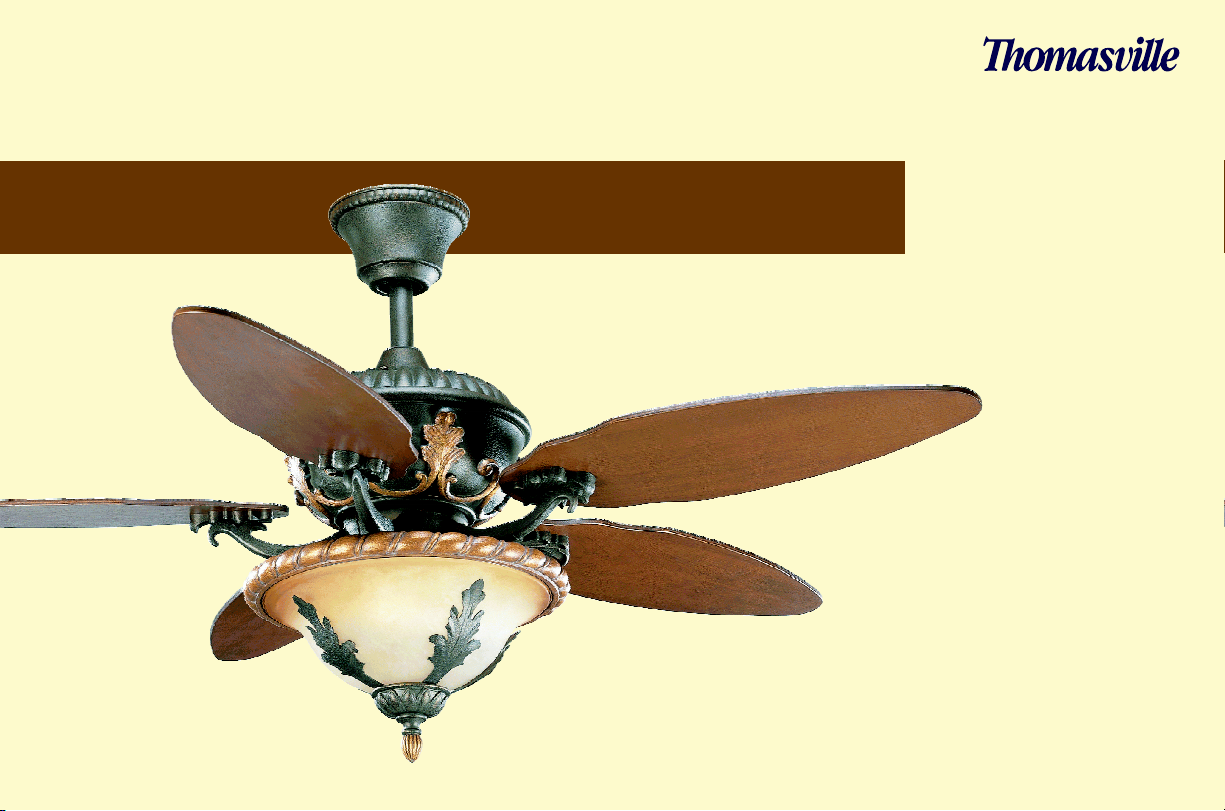
Provence
collection
L I G H T I N G
TM
P2506
Page 2

THOMASVILLE LIGHTING Lifetime Limited Warranty
THOMASVILLE LIGHTING FAN MOTORS ARE WARRANTED TO THE END USER TO
BE FREE OF ELECTRICAL AND/OR MECHANICAL DEFECTS FOR A LIFETIME FROM
DATE OF SALE. PULL CHAIN SWITCHES, REVERSE SWITCHES, CAPACITORS AND
METAL FINISHES ARE WARRANTED FOR A PERIOD OF 1 YEAR. WARPING OF
WOODEN OR PLASTIC BLADES IS NOT COVERED BY THIS WARRANTY.
THE END USER HAS THE OPTION OF RETURNING THE DEFECTIVE FAN TO THE
PLACE OF PURCHASE DURING THE FIRST 30 DAYS FOR A REPLACEMENT. AFTER
30 DAYS, THE PURCHASER MUST CONTACT THOMASVILLE LIGHTING FOR
REPAIR OR REPLACEMENT. THE END USER ALSO BEARS THE RESPONSIBILITY
FOR ALL COSTS IN THE REMOVAL, SHIPPING AND REINSTALLATION OF FANS OR
PARTS FOR REPAIR OR REPLACEMENT.
THOMASVILLE LIGHTING WILL NOT ASSUME LIABILITY OR RESPONSIBILITY
FOR DAMAGES (INCLUDING INCIDENTAL OR CONSEQUENTIAL) CAUSED BY
THE IMPROPER INSTALLATION OR OPERATION OF THE UNIT OR ITS COMPONENT
PARTS, OR BY THE FAILURE OF SUPPORTING HARDWARE NOT SUPPLIED BY
THOMASVILLE LIGHTING. THIS WARRANTY IS GIVEN IN LIEU OF ALL OTHER
GUARANTEES, WHETHER EXPRESSED OR IMPLIED, AND IS VOIDED IN CASES OF
ABUSE, MISUSE OR IMPROPER HANDLING, NEGLIGENCE, SHIPPING DAMAGE,
UNAUTHORIZED REPAIRS (MADE OR ATTEMPTED) OR UNUSUAL APPLICATION.
SOME STATES DO NOT ALLOW LIMITATIONS ON HOW LONG AN IMPLIED
WARRANTY LASTS OR THE EXCLUSION OR LIMITATIONS OF INCIDENTAL OR
CONSEQUENTIAL DAMAGES, SO THE ABOVE LIMITATIONS AND EXCLUSIONS
MAY NOT APPLY TO YOU. THIS WARRANTY GIVES YOU SPECIFIC RIGHTS AND
YOU MAY HAVE OTHER RIGHTS WHICH VARY FROM STATE TO STATE.
Date Purchased
Store Purchased
UL Model No. 54-TS
Serial No.
Vendor No. 5523
UPC
785247129188
THOMASVILLE LIGHTING Lifetime Limited Warranty
Page 3
Safety Rules
1
Unpacking Your Fan 2
Installing Your Fan 3
Operating Your Fan
11
Operating Your Remote Control
12
Care of Your Fan
13
Troubleshooting
14
Specifications
15
Table of Contents
Page 4
1.Safety Rules
READ AND SAVE THESE INSTRUCTIONS
1. To reduce the risk of electric shock, insure electricity has
been turned off at the circuit breaker or fuse box before
beginning.
2. All wiring must be in accordance with the National
Electrical Code ANSI/NFPA 70-1999 and local electrical
codes. Electrical installation should be performed by a
qualified licensed electrician.
3. WARNING: To reduce the risk of fire or electric shock,
this fan should only be used with fan speed control part
no.:UC7067RYL manufactured by Rhine Electronic Co., Ltd.
4. CAUTION: To reduce the
risk of personal injury, use
only the screws provided with the outlet box.
5. The outlet box and support structure must be securely
mounted and capable of reliably supporting a minimum of 50
pounds. Use only UL Listed outlet boxes marked "Acceptable
for fan support of 22.7 kgs (50 lbs) or less".
WARNING
TO REDUCE THE RISK OF FIRE, ELECTRIC SHOCK OR PERSONAL
INJURY, MOUNT TO OUTLET BOX MARKED ACCEPTABLE FOR FAN
SUPPORT OF 22.7 KGS (50 LBS) OR LESS AND USE SCREWS
PROVIDED WITH THE OUTLET BOX.
6. The fan must be mounted with a minimum of 7 feet
clearance from the trailing edge of the blades to the floor.
7. Avoid placing objects in the path of the blades.
8. To avoid personal injury or damage to the fan and other
items, be cautious when working around or cleaning the fan.
9. Do not use water or detergents when cleaning the fan or
fan blades. A dry dust cloth or lightly dampened cloth will be
suitable for most cleaning.
10. After making electrical connections, spliced conductors
should be turned upward and
pushed carefully up into outlet
box. The wires should be spread apart with the grounded
conductor and the equipment-grounding conductor on one side
of the outlet box.
11. Electrical diagrams are for reference only. Light kits that
are not packed with the fan must be UL Listed and marked
suitable for use with the model fan you are installing. Switches
must be UL General Use Switches. Refer to the instructions
packaged with the light kits and switches for proper assembly.
WARNING
TO REDUCE THE RISK OF PERSONAL INJURY, DO NOT BEND
THE BLADE BRACKETS (ALSO REFERRED
TO AS "FLANGES")
DURING ASSEMBLY OR AFTER INSTALLATION. DO NOT
INSERT OBJECTS IN THE PATH OF THE BLADES.
WARNING
TO REDUCE THE RISK OF SHOCK. THIS FAN MUST BE
INSTALLED WITH AN ISOLATION WALL CONTROL/SWITCH.
WARNING
THIS PRODUCT CONTAINS CHEMICALS KNOWN TO THE STATE
OF CALIFORNIA TO CAUSE CANCER, BIRTH DEFECTS AND/OR
OTHER REPRODUCTIVE HARM. THOROUGHLY WASH HANDS
AFTER INSTALLING, HANDLING, CLEANING, OR OTHERWISE
TOUCHING THIS PRODUCT.
Page 5
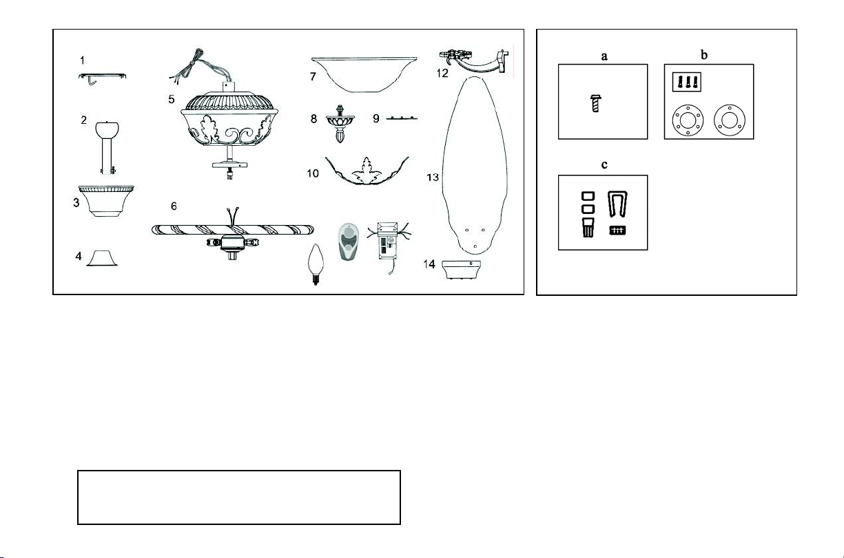
Unpacking Your Fan 2.
1. Mounting Plate (inside Canopy)
2. Downrod and Ball Assembly
(with hanger pin and locking pin
pre-attached)
3. Canopy
4. Decorative Motor Collar Cover
5. Fan Motor Assembly
6. Light Kit Plate
7. Glass Shade
8. Bottom Cover, Finial and
Threaded Tube
9. Extra 45-degree Canopy
Bottom Cover
10. Decorative Glass Accent
11. Hand Unit/ Receiver
(a 12V battery included)
12. Blade Brackets (5)
(with blade bracket screws
pre-installed)
13. Blades (5)
14. Switch Cup
a) Blade Attachment Hardware
(15 washer head screws)
b) Mounting Hardware
(1 plastic gasket, 1 metal gasket, 3
screws & lock-washers)
c) Electric Hardware & Balancing
Kit
(3 plastic wire connectors, blade
balancing kit)
d) Mounting Hardware (2 extra
mounting screws #10-32 for outlet
box)
IMPORTANT
PLEASE REMOVE RUBBER STOPS FROM THE FAN
MOTOR BEFORE INSTALLING BLADES OR TESTING
MOTOR.
15
15. Bulbs (2)
Page 6
Tools Required
Phillips screw driver, straight slot
screw driver, adjustable wrench, step
ladder, and wire cutters.
Mounting Options
If there isn't an existing mounting box,
then read the following instructions.
Disconnect the power by removing
fuses or turning off circuit breakers.
Secure the outlet box directly to the
building structure. Use appropriate
fasteners and building materials. The
outlet box and its support must be able
to fully support the moving weight of
the fan (at least 50 lbs.). Do not use
plastic outlet boxes.
WARNING
TO REDUCE THE RISK OF FIRE,
ELECTRIC SHOCK, OR OTHER
PERSONAL INJURY, MOUNT FAN ONLY TO
AN OUTLET BOX MARKED OF 22.7 KGS
(50 LBS) OR LESS AND USE THE
MOUNTING SCREWS PROVIDED WITH
THE OUTLET BOX. OUTLET BOXES
COMMONLY USED FOR THE SUPPORT OF
LIGHTING FIXTURES MAY NOT BE
ACCEPTABLE FOR FAN SUPPORT AND
MAY NEED TO BE REPLACED. CONSULT A
QUALIFIED ELECTRICIAN IF IN
DOUBT.
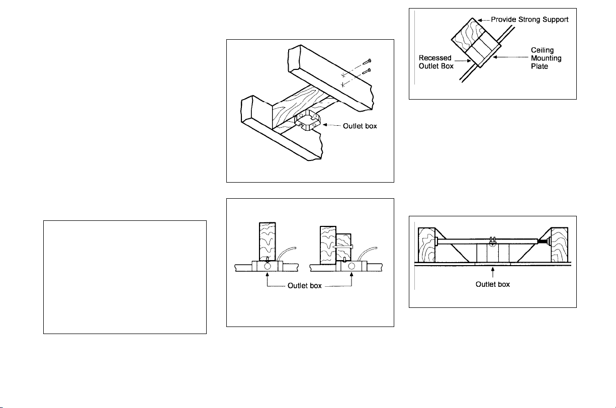
Figures l, 2, and 3 are examples of
different ways to mount the outlet box.
Figure 1
Figure 2
Figure 3
Note: You may need a longer
down-rod to maintain proper blade
clearance when installing on a steep,
sloped ceiling. The maximum angle
allowable is 45 degrees. Note: For
mounting angles between 20-45
degrees, please replace the canopy
bottom cover installed on the bottom
of the canopy opening with the extra
45-degree canopy bottom cover
included.
Figure 4
To hang your fan where there is an
existing fixture but no ceiling joist,
you may need an installation hanger
bar as shown in Figure 4 (available at
your Thomasville Lighting Retailer).
3.Installing Your Fan
Page 7

Hanging the Fan
REMEMBER to turn off the power.
Follow the steps below to hang your
fan properly.
NOTE: This ceiling fan is supplied
with two types of hanging assemblies;
the standard ceiling installation using
the ball/ downrod assembly mounting,
and the "close-to-ceiling" mounting.
The "close-to-ceiling" mounting is
recommended in rooms with less than
8-foot ceilings or in areas where
additional space is desired from the
floor to the fan blades. When using
standard downrod installation, the
distance from the ceiling to the bottom
of the fan blades will be approximately
14.5 inches. The "close-to-ceiling"
installation reduces the distance from
the ceiling to the bottom of the fan
blades to approximately 9 inches.
STANDARD CEILING MOUNTING
Note: For mounting angles between
20-45 degrees, please replace the
canopy bottom cover installed on the
bottom of the canopy opening with
the extra 45-degree canopy bottom
cover included.
1. Remove the canopy ring from the
canopy by turning the ring to the right
until it unlocks (Figure5).
Figure 5
2. Remove the mounting plate from
the canopy by loosening the four
screws on the top of the canopy.
Remove the two non-slotted screws
and loosen the slotted screws. This will
enable you to remove the mounting
plate (Figure 6).
Figure 6
3. Remove the hanger pin and
locking pin from downrod assembly.
4. Route the wires exiting the top of
the fan motor through the decorative
motor collar cover then the canopy
ring. Make sure the slot openings are
on top. Route the wires through the
canopy and then through the
ball/downrod assembly (Figure 7).
5. Loosen, but do not remove, the set
screws on the collar on the top of the
motor housing.
4.
Page 8
Canop
y
Bottom Cover
"
6. Align the holes at the bottom of
the downrod with holes in the collar on
top of the motor housing (Figure 7).
Carefully insert the hanger pin through
the holes in the collar and downrod. Be
careful not to jam the pin against the
wiring inside the downrod. Insert the
locking pin through the hole near the
end of the hanger pin until it snaps into
its locked position as noted in the
circle inset of Figure 7.
7. Re-tighten the set screws on the
collar on the top of the motor housing.
WARNING
FAILURE TO PROPERLY INSTALL
LOCKING PIN AS NOTED IN STEP 6
COULD RESULT IN FAN LOOSENING AND
POSSIBLY FALLING.
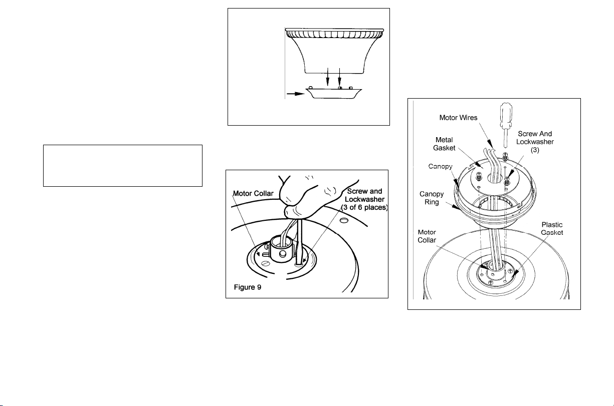
CLOSE-TO-CEILING
MOUNTING
1. Remove the canopy ring from the
canopy by turning the ring to the right
until it unlocks (Figure 5).
2. Remove the mounting plate from
the canopy by loosening the four
screws on the top of the canopy.
Remove the two non-slotted screws
and loosen the slotted screws. This
will enable you to remove the
mounting plate (Figure 6).
3. Remove the decorative canopy
bottom cover from the canopy by
depressing the three studs (Figure 8).
Figure 8
4. Remove three of the six screws and
lockwashers (every other one) securing
the motor collar to the top of the fan
motor housing (Figure 9).
5. Route the wires exiting the top of the
fan motor through the plastic gasket,
canopy ring, canopy and the metal
gasket, place the plastic gasket over the
remaining three screws, place the
canopy ring, canopy and the metal
gasket over the motor collar at the top
of the fan motor (Figure 10).
6. Align the three mounting screw holes
on the metal gasket with the holes on
the motor collar at the top of the fan
motor and fasten, using the three screws
and lockwashers provided with metal
gasket.
7. Tighten the three mounting screws
securely.
Figure 10
5.
Page 9
Installing Fan to the
Electrical Box
THE OUTLET BOX AND
SUPPORT STRUCTURE MUST
BE SECU
RELY MOUNTED AN
D
CA
P
ABLE
OF RELIABLY
SU
P
P
ORTI
NG A MINIMUM
OF
50 POU
ND
S.
USE ONLY
UL
LISTED OUTLET BO
X
ES
MARK
ED
“ACCEPTABLE FOR
FAN SUPPORT
OF 22.7 KGS (50
LBS) OR LESS”.
1. Pass the 120-volt supply wires
through the center hole in the ceiling
mounting plate as shown in Fig.11.
2. Install the ceiling mounting plate
on the electrical box by using the mounting screws provided with the electrical box.When using the close-to-ceiling
mounting, it is important that the mounting plate be level. If necessary, use leveling washers(not supplied)between the
mounting plate and electrical box. Note
that the flat side of the mounting plate is
toward the electrical box.(Fig.11)
3. Tighten the two screws on the electrical box securely.
6.
CONNECTING THE SAFETY
CABLE
a. Place the looped end of the safety
cable around the untightened wood
screw as shown in Figure 11a.
b. Tighten the wood screw securing
the safety cable.
C
AUTI
ON: In order to
e
xten
d the
length of
the
safety cable,
please
use
braided steel cable of t
he
sam
e
thickness
or
greater
and
secu
re
according to lo
cal and national electric
codes. Please
Con
s
ult a qualified
electrician if you are in doubt.
4. Carefully lift the fan assembly up to
the ceiling mounting plate and hang the
fan on the hook provided by utilizing
one of the holes at the outer rim of the
ceiling canopy.(Fig.12a,12b)
Page 10
Making the Electrical
Connections
REMEMBER to disconnect the power.
If you feel that you do not have enough
electrical wiring knowledge
o
r
exp
e
rience,
h
ave your fan
installed by a
licensed
electrician.
Follow
t
he steps below
to
c
o
nnect the
fan to your hou
sehold
wirin
g. Use the
wire connecting nuts
supplied with your
fan
and supplied
with remote control.
Secure the connectors with electrical
tape. Make sure there are no loose
st
ra
n
ds or
connections (Figure 13).
l. Connect both gre
e
n wires from the
do
w
n-rod and mounting pl
ate
t
o the
bare
c
opper (Ground)
fro
m the electrical
bo
x.
2. Connect the black wire (AC IN L)
fro
m the receiver unit to the bla
c
k wire
from the electrical box.
3. Connect the white wire (AC IN N)
from
the
receiver unit to the white wire
from the
electrical box.
4. Connect the white wire (T
o
Motor
N) from
the
receiver unit
to the white
wire fro
m
the fan assem
b
ly.
5. Connect the black wire (To Motor
L) from the receiver to the black wire
from the fan assembly.
6. Connect the blue wire (For Light.)
from the receiver to the blue wire from
the fan.
After wires ar
e connected,
carefully
tuck
them
into
the
electrical box. Insert
the recei
ver unit into
the m
ounting
p
lat
e; make sure the black antenn
a
wire
sits
on top of the
receiver
un
it.
NOTE
THE FREQUENCIES ON YOUR RECEIVER
AND
T
RANSMITTER
H
AVE BEE
N
PRESET
AT
THE
FACTOR
Y
,
BEFORE INSTALLING THE
RECEIVER,
MAKE SURE THE DIP SWI
TCHES
ON THE
RECEIVER AND TRANSMITTER ARE
SET
T
O THE SAME FREQUENC
Y
. THE DIP
SWITCH
ES
O
N
THE TRANSMITTER
ARE
LOCATED INSIDE THE BATTERY
COMPAR
TMENT.
WARNING
EACH WIRE
NU
T (WI
RE CONNECTOR)
SUPPLIED WITH THIS FAN IS DESI
GNED TO
ACCEPT
UP TO
ONE 12 GAUGE HOUSE W
I
RE
AND TWO
WIRES FROM THE FAN. IF
YO
U
H
A
VE
LARGE
R THAN 12 GAUGE HOUSE
W
I
R
ING O
R
MORE THAN ONE HOUSE WIRE
T
O CONNECT TO
THE FAN WIRING,
CONSULT
AN ELECTRIC
I
AN FOR THE
PROPER
SI
ZE WIRE
NUTS
T
O
USE.
7.
Page 11
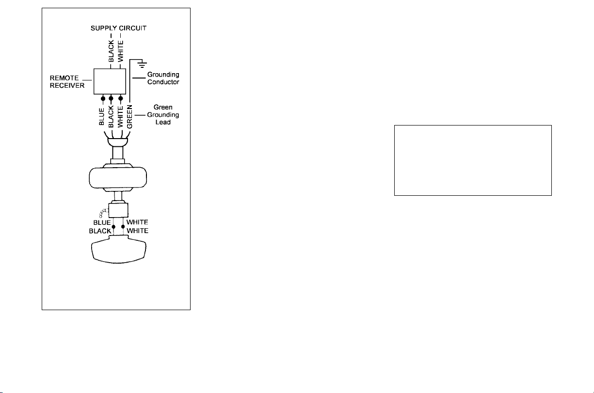
Figure 13
Finishing the Fan
Installation
STANDARD CELING MOUNTING
1. Carefully lift the canopy up to the
mounting plate . Make sure the tab in
the ring at the bottom of the canopy is
properly seated in the groove in the
hanger ball. Align the locking slots of
the ceiling canopy with the two screws
in the mounting plate. Push up to
engage the slots and turn clockwise to
lock in place. Immediately tighten the
two mounting screws firmly.
2. Install the remaining two mounting
screws into the holes in the canopy and
tighten firmly.
3. Install the decorative canopy ring
by aligning the ring’s slots with the
screws in the canopy. Rotate the ring
counter-clockwise to lock in place.
4. You may now proceed to attaching
the fan blades
.
CLOSE-TO-CEILING MOUNTING
1. Carefully unhook the fan from the
mounting plate and align the locking
slots of the ceiling canopy with the two
screws in the mounting plate. Push up to
engage the slots and turn clockwise to
lock in place. Immediately tighten the
two mounting screws firmly.
2. Install the remaining two mounting
screws into the holes in the canopy and
tighten firmly.
3. Install the decorative canopy ring
by aligning the ring’s slots with the
screws in the canopy. Rotate the ring
counter-clockwise to lock in place.
4. You may now proceed to attaching
the fan blades.
WARNING
LOCKING SLOTS OF CEILING
CANOPY ARE PROVIDED ONLY AS
AN AID TO MOUNTING. DO NOT
LEAVE FAN ASSEMBLY
UNATTENDED UNTIL ALL FOUR
CANOPY SCREWS ARE ENGAGED
AND FIRMLY TIGHTENED.
8.
Page 12

Attaching the Fan
Blades
1. Attach the blade to blade bracket
using the three screws as shown in figure
14. Start a screw into the bracket. Repeat
for the two remaining screws.
2. Tighten each screw securely.
3. Fasten the blade assembly to the
motor by inserting the alignment post
into the slot on the bottom of the motor
and tightening the blade bracket screws.
Please note that the blade bracket screws
are pre-installed into the blade bracket.
(Figure 15).
4. Repeat steps 1, 2 & 3 for the
remaining blades.
Blade Balancing
All blades are grouped by weight.
Because natural woods vary in density,
the fan may wobble even though the
blades are weight matched. The
following procedure should correct most
fan wobble. Check after each step.
1. Check that all blade and blade
bracket screws are secure. Most fan
wobble problems are caused when blade
levels are unequal. Check this level by
selecting a point on the ceiling above the
tip of one of the blades. Measure from a
point on the center of each blade to the
point on the ceiling. Measure this
distance as shown in Figure 16. Rotate
the fan until the next blade is positioned
for measurement. Repeat for each blade.
Measurements deviation should be
within 1/8". Run the fan for 10 minutes.
2. Use the enclosed Blade Balancing
Kit if the blade wobble is still noticeable.
Installing the Light Kit
/ Glass Shade
REMEMBER to disconnect the power.
THE GLASS IS FRAGILE, USE CARE
WHEN INSTALLING THE LIGHT KIT
AND THE GLASS SHADE.
1. Loosen the two screws on the
opposite side of four mounting screws
on the bottom of the switch cup ;
remove the other two screws (Figure
17a).
9.
Page 13

2. Route the Black and White wires
exiting the top of the light kit plate
through the center hole on the bottom
of the switch cup.
3. Connect the Black and White wires
exiting the light kit plate with the Blue
and White wires exiting the switch cup
by connecting the 1-positioned molded
adaptor plugs together (Black to Blue ;
White to White).
4. Align the two key slotted holes in the
light kit plate with the two mounting
screws that were loosened in step 1 ,
place the light kit plate over the two
mounting screws and rotate the light
kit plate to the right until it locks. Align
the two non-slotted holes in the light kit
plate with the two screw holes in the
bottom of the switch cup , install the
other two mounting screws that were
removed in step 1 and secure firmly
(Figure 17a).
5. Remove the three mounting screws
on the light kit bracket below tbe motor.
6. Connect the wires exiting the
bottom of the motor with the light kit by
connecting the 9 positioned molded
adaptor plugs together.
7. Slide the light kit and secure it to the
light kit bracket using the three screws
that were removed in step 5 (Figure
17b).
8. Remove the finial, bottom cover,
and then remove the two hex nuts and
one rubber wa
sher from the threaded
tube, install the threaded tube onto the
stem of the light kit assembly and secure
with one of the two hex nuts (Figure
17b).
9. With power off, insert 2 candelabra
base bulbs into the sockets, Max. 60w
(provided).
10. Raise the glass shade and
decorative glass accent up against the
light kit assembly and secure properly
with rubber washer and the hex nut, DO
NOT OVERTIGHTEN THE HEX NUT,
OVERTIGHTEN THE HEX NUT MAY
CAUSE GLASS TO BREAK. Finally
secure with the bottom cover and the
finial (Figure 17b).
NOTE: ALLOW THE
BULBS TO
COOL COMPLETELY BEFORE
TOUCHING OR REPLACING THE
BULBS TO AVOID ACCIDENTAL
BURNING OF THE SKIN.
10.
(provided)
WARNING:Over lamping the fan will
result in the fan lights shutting down until
the proper wattage of bulbs are installed.
Reset the lights by turning off, replace bulbs
with the correct wattage bulbs,Turn power
on.
Page 14

NOTE
DO NOT WAIT FOR THE FAN TO STOP TO
PRESS THE REVERSE BUTTON. THE FAN
WILL NOT REVERSE IF THE FAN IS NOT
MOVING.
The hand unit controls directions
(forward or reverse).
Speed settings for warm or cool weather
depend on factors such as the room size,
ceiling height, number of fans, and so
on.
Warm weather- (Forward) A downward
air flow creates a cooling effect as shown
in Figure 18. This allows you to set your
air conditioner on a higher setting
without affecting your comfort.
Cool weather- (Reverse) An upward
airflow moves warm air off the ceiling
area as shown in Figure 19. This allows
you to set your heating unit on a lower
setting without affecting your comfort.
11.Operating You Fan
Page 15

Operating Your Remote Control 12.
Setting the Code
This unit has 16 different code combinations.
To set the code, perform the following steps.
A. Setting the code on the transmitter:
a. Remove the battery cover from the battery
compartment in the back side of the transmitter.
b. Slide code switches to your choice of up or down
position (factory setting is all up).
B. Setting the code on the receiver:
a. Slide code switches to the same position as set on
your transmitter.
b. Re-place the battery cover on the battery compartment
of the transmitter.
CAUTION: Ceiling angle shall not exceed 45 degrees.
Remote Control Model: UC7067RYL
Installing Receiver
WARNING: To reduce the risk of fire or electric shock,
remember to disconnect power. Do not use solid state fans,
electrical wire must meet all local and national electrical code
requirement. Electrical source and fans must be 115/120 volt,
60Hz. Maximum fan motor amps: 1.0. Maximum light watts:
300-incandescent only.
A. Wire connection:
Fan Green Wire
Bare Supply Wire
Black Receiver Wire (AC IN L)
Black Supply Wire
White Receiver Wire(AC IN N)
White Supply Wire
White receiver Wire(TO MOTOR N)
White Fan Wire
Black Receiver Wire(TO MOTOR L)
Black Fan Wire
Blue Receiver Wire(FOR LIGHT)
Blue Light Wire
NOTE: If other fan or supply wires are different color, have
this unit installed by a licensed electrician.
B. Lay the black antenna wire on top of the receiver and slide
the receiver into the mounting plate.
Operating Transmitter
Install a 12 volt battery ( included).
This remote is equipped with 16 code combinations. To
prevent possible interference from or to other remote units
such as garage door openers, car alarm or security system,
simply change the combination code but be sure that the code
on both transmitter and receiver are matched.
This device complies with par
t 15 of the FCC rules. Operation
is subject to the following two conditions:(1) This device may
not cause harmful interference and (2) This device must accept
any interference received, including interference that may
cause undesired operation.
Operating the fan:
●●● Key---High Speed
●● Key--Medium Speed
● Key---Low Speed
Key---Light On/Off and Dimmer
Key (inside the battery compartment in the back side of
the transmitter) -Fan Reversing Function
" Key---Fan Off
Page 16

13.Care of Your Fan
Here are some suggestions to help you
maintain your fan.
1. Because of the fan's natural
movement, some connections may
become loose. Check the support
connections, brackets, and blade
attachments twice a year. Make sure
they are secure. (It is not necessary to
remove fan from ceiling.)
2. Clean your fan periodically to
help maintain its new appearance over
the years. Do not use water when
cleaning. Use only a soft brush or
lint-free cloth to avoid scratching the
finish. The plating is sealed with a
lacquer to minimize discoloration or
tarnishing. This could damage the
motor, or the wood or possibly cause
an electrical shock.
5. You can apply a light coat of
furniture polish to the wood for
additional protection and enhanced
beauty. Cover small scratches with a
light application of shoe polish.
4. There is no need to oil your fan.
The motor has permanently lubricated
sealed ball bearings.
WARNING
MAKE SURE THE POWER IS OFF AT THE
ELECTRICAL PANEL BOX BEFORE YOU
ATTEMPT ANY REPAIRS. REFER TO THE
SECTION, "MAKING ELECTRICAL
CONNECTIONS."
Page 17

Troubleshooting 14.
Problem Solution
Fan will not start.
Fan sounds noisy.
1. Check main and branch circuit fuses or breakers.
2. Check line wire connections to the fan and switch wire connections in the switch housing.
CAUTION: Make sure main power is off.
3. Check battery in the transmitter. Does the red LED light come on? Are you standing close
enough to the fan (normal range is 10-20 feet)? Are the dip switch settings the same on the
transmitter (hand unit) and receiver? REMEMBER TO TURN OFF POWER SUPPLY
BEFORE CHECKING THE DIP SWITCH SETTINGS IN RECEIVER.
1. Make sure all motor housing screws are snug.
2. Make sure the screws that attach the fan blade bracket to the motor hub are tight.
3. Make sure wire nut connections are not rattling against each other or the interior wall of the
switch housing.
CAUTION: Make sure main power is off.
4. Allow a 24-hour "breaking-in" period. Most noises associated with a new fan disappear during
this time.
5. If using the Ceiling Fan light kit, make sure the screws securing the glassware are tight. Check
that the light bulb is also secure.
6. Make sure the canopy is a short distance from the ceiling.
It should not touch the ceiling.
7. Make sure your ceiling box is secure and rubber isolator pads were used between the hanger
bracket and ceiling box.
Page 18

FAN SIZE SPEED VOLTS AMPS WATTS RPM N.W. G.W. C.F.
Low 120 0.33 14 60
Med. 120 0.47 33 100
54”
High 120 0.65 78 165
39.0
Lbs
45.6
Lbs
3.11
These are approximate measures. They do not include Amps and Wattage used by the light kit.
2011 Thomasville Lighting Inc.
701 Millennium Blvd.,
Greenville, SC 29607
All Rights Reserved
15.Specifications
Page 19

Garantía Limitado del Curso de la Vida
Garantía Limitado del Curso de la Vida
LOS VENTILADORES THOMASVILLE LIGHTING SE AUTORIZAN AL USUARIO DEL
EXTREMO PARA ESTAR LIBRES DE LOS DEFECTOS ELÉCTRICOS Y/O MECÁNICOS
PARA UN CURSO DE LA VIDA. LOS INTERRUPTORES CON CADENA, LOS
INTERRUPTORES DE INVERSIÓN, LOS CONDENSADORES Y LAS TERMINACIONES
METÁLICA ESTÁN GARANTIZADAS POR UN PERÍODO DE 1 AÑO. LAS PALETAS
PANDEADAS DE MADERA O PLÁSTICO NO ESTÁN CUBIERTAS POR ESTA
GARANTÍA.
EL CONSUMIDOR TIENE LA OPCIÓN DE DEVOLVER EL VENTILADOR DEFECTUOSO
PARA SU CAMBIO AL NEGOCIO DE ADQUISICIÓN DURANTE LOS 30 DÍAS
SIGUIENTES. DESPUÉS DE 30 DÍAS, EL COMPRADOR DEBE CONTACTAR
THOMASVILLE LIGHTING PARA LA REPARACIÓN O REEMPLAZO. EL CONSUMIDOR
SE HARÁ CARGO DE TODOS LOS COSTOS DE TRANSPORTE, EXPEDICIÓN Y
REINSTALACIÓN DE LOS VENTILADORES O DE LAS PARTES PARA REPARAR O
REEEMPLAZAR.
THOMASVILLE LIGHTING NO ASUMIRÁ OBLIGACIONES O RESPONSABILIAD POR
DAÑOS (INCLUYENDO INCIDENTALES O CONSIGUIENTES) CAUSADOS POR EL USO
O LA INSTALACIÓN IMPROPIA DE LA UNIDAD O DE SUS PARTES COMPONENTES, O
POR LA FALLA DEL EQUIPO DE SOPORTE NO SUMINISTRADO POR THOMASVILLE
LIGHTING. ESTA GARANTÍA ESTÁ DADA EN LUGAR DE TODAS LAS OTRAS
GARANTÍAS, SEAN ÉSTAS EXPRESAS O IMPLÍCITAS, Y ES INVÁLIDA EN CASOS
DE ABUSO, USO O MANEJO INCORRECTOS, TRATAMIENTO NEGLIGENTE, DAÑOS
OCASIONADOS POR EL TRANSPORTE, REPARACIONES NO AUTORIZADAS
(REALIZADAS O TENTATIVAS) O APLICACIÓN INUSUAL.
ALGUNOS ESTADOS NO RECONOCEN LIMITACIONES EN EL TÉRMINO DE LA
GARANTÍA IMPLICADA O LA EXCLUSIÓN O LIMITACIÓN DE LOS DAÑOS
INCIDENTALES O CONSIGUIENTES, ENTONCES LAS LIMITACIONES Y
EXCLUSIONES PRECEDENTES PUEDEN NO SER APLICABLES A UD. ESTA
GARANTÍA LE OTORGA DERECHOS ESPECÍFICOS Y UD. PUEDE TENER OTROS
DERECHOS QUE VARÍEN DE ESTADO EN ESTADO.
Fecha de Compra
Lugar de compra
No. de Modelo UL 54-TS
No. de Serie
No. de Vendedor 5523
UPC 785247129188
Page 20

Reglas de Seguridad 1
Cómo Desembalar Su Ventilador 2
Cómo Instalar Su Ventilador 3
Cqmo Operar Su Ventilador 11
Operarciqn del Control Remoto 12
Mantenimiento De Su Ventilador
13
Solución De Problemas
14
Especificaciones
15
Indice
Page 21

1. Reglas de Seguridad
LEA Y GUARDE ESTAS INSTRUCCIONES
1. Para reducir el riesgo de una electrocución, asegurese de
cortar el suministro eléctrico apagando los cortocircuitos o la
caja de fusibles, antes de comenzar.
2. Todo cableado debe realizarse conforme al Código
Nacional de Electricidad "ANSI/ NFPA 70-1999" y los códigos
eléctricos locales. La instalación eléctrica deberá ser hecha por
un electricista calificado y licenciado.
3. PRECAUCION: Para reducir el riesgo de una
electrocucion, este ventilador debe usar unicamente controles de
velocidad modelo UC7067RYL, fabricado por Rhine Electronics
Co., Ltd.
4. ADVERTENCIA: Para reducir el riesgo de da
ño personal,
usar solamente los dos tornillos de acero (y arandelas de
seguridad) suministrados y montar el ventilador en una caja de
distribución designado "aceptable para soportar ventilador".
5. La caja de distribucion y el soporte de la estructura debe
estar seguramente montado y ser capas de confiablemente
soportar el minimo de 22.7kgs (50lbs) o menos.
6. El ventilador debe ser instalado con un mínimo de 7 pies
(218 cm) desde la parte más baja del aspa hasta el piso.
ADVERTENCIA
PARA REDUCIR EL RIESGO DE INCENDIO, CHOQUE ELECTRICO O
DAÑO PERSONAL, MONTE LA CAJA DE DISTRIBUCION MARCADA
ACEPTABLE PARA SOPORTE DE VENTILADOR DE 22.7KGS (50LBS)
O MENOS Y USE LOS TORNILLOS PROVEIDOS CON LA CAJA DE
DISTRIBUCION.
7. Evite colocar objetos que interfiera el giro de las aspas.
8. Para evitar daños personales o daños al ventilador y otros
artículos, tener cuidado cuando esté trabajando alrededor o
limpiando el ventilador.
9. No usar agua o detergente al limpiar el ventilador o las
aspas. Un paño seco o ligeramente húmedo será suficiente para
limpiar.
10. Después de hacer las conexiones eléctricas los conductors
empalmados, deben ser girados hacia arriba y empujados
cuidadosamente adentro de la caja de distribución. Los cables
deben ser se
parados: con el conductor a tierra y el conductor a
tierra del equipo en un lado de la caja de distribución.
11. Los diagramas eléctricos son solamente para referencia.
Los conjuntos de luces que no son suministrados con el
ventilador, deben ser aceptados por las normas U.L. y para uso
con el modelo de ventilador que Ud. está instalando. Los
interruptores deben ser aprobados por U.L. Consulte las
instrucciones suministradas con el conjunto de luces e
interruptores por una instalación apropiada.
ADVERTENCIA
PARA REDUCIR EL RIESGO DE DAÑO PERSONALES, NO DOBLE LAS
SOPORTES DE LAS ASPAS DURANTE EL ENSAMBLAJE O DESPUES
DE LA INSTALACION. NO INTRODUACZ OBJETOS.
AVISO
PARA REDUCIR EL RIESGO DE DESCARGA, ESTE VENTILADOR
DEBERA SER INSTALADO CON UN INTERRUPTOR/CONTROL DE
PARED.
ADVERTENCIA
ESTE PRODUCTO CONTIENE SUBSTANCIAS QULMICAS QUE SEGUN EL
ESTADO DE CALIFORNIA CAUSA CANCER, DEFECTOS DE NACLMLENTO
Y (O) DANO AL SISTEMA REPRODUCTOR. LAVARSE BIEN LAS MANOS
DESPUES DE INSTALAR, MANIPULAR, LIMPIAR O TOCAR DE MANERA
ALGUNA ESTE PRODUCTO.
Page 22

2. ómo DesembalarSu Ventilador
1. Plato de Montaje (Dentro del
Escudete)
2. Ensamblaje de Tubo y Rotula
(perno y chaveta de seguridad
pre-instalados)
3. Escudete
4. Cubierta Decorativa del Collar del
Motor
5. Ensamblaje del Motor
6. Plato del sistema de luz
7. Pantalla de Vidrio
8. Tapa Inferior, Tubo de Rosca Final
9. Cubierta de Escudete de 45 grados
adicional
10. Accesorio Decorativo del Cristal
11. Unidad Manual / Recibidor
(una bateria de 12 voltios incluida)
12. Soporte de Aspa (5) (incluye
tornillos pre-instalados)
13. Aspas (5)
14. Cubierta del Cableado
a) Componentes para montar la
paleta (15 tornillos con cabeza de
arandela)
b) Componentes de montaje ( 1 sello
plastico, 1 sello metalico, 3 tornillos
y arandelas)
c) Componentes eléctricos y Kit para
equilibrar (3 conectores p lásticos
para cables, kit para equilibrar la
paleta)
d) Componentes para montar el
Montaje (2 tornillos # 10-32
adicional)
IMPORTANTE
POR FAVOR REMUEVA LAS GOMAS LOCALIZADAS EN LA ARTE
INFERIOR DEL VENTILADOR ANTES DE INSTALAR LAS ASPAS O
PROBAR EL MOTOR DEL VENTILADOR.
15
15. Bombillas (2)
C
Page 23

3. Cqmo Instalar Su Ventilador
Herramientas Necesarias:
Desarmador de cruz, desarmador plano,
pinzas ajustables, cortadoras de alambre
y cinta aislante
Opciones De Montaje
Si no existe una caja de distribucion
instalada, siga las siguientes
instrucciones. Desconecte la energia
electrica apagando los interruptores
del circuito o sacando los fusibles.
Asegure la caja de distribucion
directamente en la estructura del edificio.
Use los soportes y materials de
construccion apropiados. La caja de
distribucion y su soporte deben de ser
capaces de soportar todo el peso en
movimiento del ventilador (minimo de
50 libras). No use cajas de distribucion
de plastico.
PRECAUCION
PARA REDUCIR EL RIESGO DE INCENDIO,
CHOQUE ELECTRICO U OTRA LESION
PERSONAL. MONTE EL VENTILADOR
SOLAMENTE EN UNA CAJA DE DISTRIBUCION O
SISTEMA DE SOPORTE QUE ESTE APROVADO
POR U.L. MARCADO ACEPTABLE PARA
SOPORTAR EL PESO DEL VENTILADOR DE 22.7
KGS (50 LBS) O MENS Y USE LOS TORNILLOS
DE MONTAJE INCLUIDOS CON LA CAJA DE
DISTRIBUCION. LA MAYORIA DE CAJAS DE
DISTRIBUCION COMUNMENTE USADAS PARA
LA INSTALACION DE LAMPARAS NO SON
ACEPTABLES PARA EL SOPORTE DE
VENTILADORES Y ES NECESARIO
REMPLAZARLAS. CONSULTE CON UN
ELECTRICISTA SI TIENE ALGUNA DUDA.
Las figuras 1, 2 y 3 muestran alternatives
diferentes para montar la caja de
distribución.
Nota: Ud. puede necesitar una barra de
extensión para mantener la distancia
apropiada de las aspas cuando la
instalación se efectúe en un techo
inclinado. El máximo ángulo
permitido es de 45 grados. Nota: Para
ángulos de instalaciq
n entre 20 y 45
grados, por favor retire la cubierta
inferior del escudete instalada en la
parte inferior de la abertura de este y
reemplácela con la cubierta de
escudete de 45 grados adicional que se
incluye en el paquete.
Para colgar su ventilador donde ya existe
una instalación pero no una viga de
techo, es posible que se necesite una
instalación de barra de suspención como
se muestra la Figura 4 (disponible en su
distribuidor Thomasville Lighting).
Figura 2
Figura 4
Figura 1
Figura3
Page 24

Colgando el Ventilador
RECORDAR cortar el suministro de
energía eléctricia. Seguir los pasos
siguientes para colgar su
ventilador apropiadamente.
NOTA: Este ventiladores suministrado
con dos métodos diferentes para ser
colgado; el mltodo estandar que incluye
el tubo descendiente con montaje de bola
y receptáculo y el montaje "prqximo al
techo". El método "próximo al techo", se
recomienda para habitaciones con menos
de 8 pies de altura o en areas donde se
requiera mayor distancia entre el piso y
las aspas del ventilador. Al usar el
método estandar de montaje con tubo, la
distáncia entre el techo y la parte más
baja de las aspas deberá ser
aproximadamente 14.5 pulgadas. El
método "próximo al techo" reduce esta
distancia a 9 pulgadas.
METODO ESTÁNDAR DE
MONTAJE
El máximo ángulo permitido es de 45
grados. Nota: Para ángulos de
instalaciq
n entre 20 y 45 grados, por
favor retire la cubierta inferior del
escudete instalada en la parte inferior
de la abertura de este y reemplácela
con la cubierta de escudete de 45
4.
grados adicional que se incluye en el
paquete.
1. Retire el anillo de la marquesina
girándolo hacia la derecha hasta que
se desenganche (Figura 5)
2. Retire la placa de montaje de la
marquesina desenroscando los cuatro
tornillos ubicados en la parte superior de
la marquesina. Retire los dos tornillos de
cabeza sin ranura y desenrosque los
tornillos de cabeza con ranura. Asi se
podrá retirar la placa de montaje (Figura 6).
Figura 5
3. Quite la perno y chaveta de seguridad
del conjunto de tubo descendente.
Figura 6
4. Pase los alambres que salen de la
parte superior del motor del ventilador
a través de la cubierta decorativa del aro
del motor y luego por el anillo de la
marquesina. Asegúrese que las ranuras
queden encima. Pase los alambres por
la marquesina y luego por el ensamblaje
de la bola/ del tubo (Figura 7).
5. Soltar pero no quitar, el tornillo
fijado que se encuentra en el collarín
encima del conjunto del motor.
6. Alinee los agujeros de la parte
inferior del tubo con los agujeros del aro
en la parte superior de la cubierta del
motor (Figura 7). Introduzca con
cuidado el pasador a través de los
agujeros del aro y del tubo. Tenga
cuidado de no empujar el pasador contra
los alambres dentro del tubo. Inserte la
chaveta en los agujeros ubicados cerca
de la extremidad del pasador hasta que
enganche en su posición cerrada como se
nota en la inserción redonda de la
Figura 7.
7. Apriete de nuevo el juego de
tornillos que esta sobre el collar en la
parte superior del caparazón del motor.
ADVERTENCIA
EL NO APPRETAR ADECUADAMENTE LA
TUERCA COMO SE MUESTRA EN EL PASO Y
NO APRETAR ADECUADAMENTE LOS
TORNILLOS COMO SE MUESTRA EN EL
PASO 6, PUEDE RESULTAR EN QUE EL
VENTILATOR SE SUELTE Y CAIGA.
Page 25

INSTALACION PRÓXIMA AL
TECHO
1. Retire el anillo de la marquesina
girándolo hacia la derecha hasta que
se desenganche (Figura 5).
2. Retire la placa de montaje de la
marquesina desenroscando los cuatro
tornillos ubicados en la parte superior de
la marquesina. Retire los dos tornillos de
cabeza sin ranura y desenrosque los
tornillos de cabeza con ranura. Asi se
podrá retirar la placa de montaje (Figura
6).
3. Remover la cubierta decorativa en la
parte de abajo del escudete presianando
los 3 botones de la cubierta (Figura 8).
Figura 8
4. Remover tres de los seis tornillos y
arandelas de seguridad (uno por
medio) asegurando el refuerzo a la
parte superior de la cubierta del motor
(Figura 9).
5. Coloque el sello plastico sobre los 3
tornillos restantes, acomode los cables
existentes en la parte superior del motor
del ventilador pasandolos a traves del
escudete. Luego coloque el anillo del
escudete y el escudete de techo sobre el
collar en la parte superior del motor
(Figura 10).
6. Alinee los agujeros de montaje con los
agujeros de la parte superior del motor y
ajuestelos usando los tres tornillos y
arandelas suministrados con el sello
metalico (Figura 10).
7. Apretar los tornillos adecuadamente.
Figura 10
5
Figura 9
Cubierta del
Escudete
Page 26

AL AJAC DE TSID RI UB IC NO Y LE
ETROPOS ED AL CURTSE T ARU BED E
R
ATSE GES U ET
NEM
AR OD
ATNOM Y
SER
AC P SA
D
E C
ONF AI
B EMEL
N ET
RATRO
POS
LE O
MINIM
DE
22.
SGK
7
)SBL05( O ME .SON
6.
CENOC T ODNA LE ELBAC DE
S GE URID DA
.a oC loque le ex ert mo evruc ado led cable
de es gu ir dad erla dedor del torn lli o de
ma ared fa lojado según lo demost odar en
al Figu ar 11 .a
b. Ap eteir le torn lli o de am de ar pa ar
rugesa ar le ca elb de se dirug ad.
A
DVERTENC
IA: Con El
F n
i De
r
ednetx
E El aL rgo le
D
e
lb
aC De
S
g
e uridad,
P
or F
va ro Use Un a
C ble D e
A
e
c
r
o
Trenzado Del
M
ismo
O
De
Ma oy r
Groso
r,
E
Inst
á
l
e
l
o
De
Ac
uerdo
A Lo
s
d
óC
i
gos socir
t
célE Lo se
l
ac Y noicaN al se .
ro
P rovaF oC nsu
e
tl Un atsi
c
irtce
lE S
i
Ti ene
.saduD
le odnalatsnI
ajaC al a rodalitneV
acirtcelE
`
led sevar
t a soitl
ov 021 ed selbac sol asaP.1
ejatnom ed etro
pos le ne lartnec oicifiro
.
11 aru
giF al artseum ol om
oc
oh
cet ed
al a o
hcet ed e
jatnom ed acalp al
elatsnI.2
-linrot
sol n
oc
alo
dnallin
r
o
ta acirtcele ajac
odnauC.e
fu
hcne
e
d ajac a
l ne s
o
tsivorp s
o
l
-tropmi se,o
hcet led ac
rec ejat
nom
le sesu
-alevin
etse ejatn
om ed
etropos le euq etna
-o
dalevin salednara asu ,oirasece
n se iS
.o
d
ejatnom e
d etropos le e
rtne)sadiul
cni o
n(sar
onalp odal le euq atoN .ac
irtcele aj
ac al y
-le ajac al aicah atse ejatnom ed
etropos le
d
.)11 a
r
ug
i
F
(acirtce
al a sollin
rot so
d
sol dadir
u
ges
no
c ete
irpA.3
.efuhcne ed
ajac
-litn
ev led odalbmasne le az
la odadiuc noC
.4
y ohcet led ejatn
o
m ed e
tro
pos le aica
h roda
,odartsi
n
imus ohcnag led ro
dalitn
ev le agleuc
-etxe edrob le ne soicifiro sol ed onu odnasu
.)b21,a21 arugiF( ohcet ed atreibuc al ed roir
Page 27

7.
Conexión del Receptor
Recuerde desconectar la electricidad
antes de comenzar la instalación ya que
podría causar descarga eléctrica u otros
daños personales.
Utilizando los con
ectad
ores d
e cables
inc
l
u
idos con el sistema
rem
oto,
h
a
ga la
s
con
exiones eléctricas como se
explica a
continuación (Fig
ura 13):
1
.
Conect
a
r
los d
os
ca
bles de tierra
del
v
entilador localizados e
n el tu
b
o o barra
y el soporte de montaje (cables verdes)
al
cab
le
tierra
del circu
it
o eléctrico
d
e
la
casa.
2. Conecte
el cabl
e
negr
o
(CA vivo)
del recib
idor
a
l
cable
negro de la
caja de
recibidor
al cable
negro de la caja de
distrib
ución.
3. Conecte
el cable
b
l
anco (C
A
neu
t
ro)
del recibido
r
al cab
l
e
b
l
a
nco de
la ca
j
a
d
e dis
trib
ución.
4.
Conecte el c
a
ble blanco (al
mo
tor
neu
t
ro) del recibidor
al cab
le
blanco
d
el conj
u
nto de ventilador.
5.
Conecte el
ca
ble negro (del motor
v
i
v
o)
del rec
i
b
i
d
or a
l cab
l
e
negr
o
del
c
onjunto de
v
e
n
tilador.
6.
Conecte el
cable
azul (pa
r
a
luz) del
recibidor al cable azul del ventilador.
Luego de conectar los cables,
introdúzcalos cuidadosamente dentro de
la caja de distribución de electricidad.
Introduzca el recibidor dentro del
soporte de m
ontaje,
aseg
urándose
que el
cable neg
ro de
la
antena quede
acostad
o
encima
del
recibidor.
N
O
TA
LAS
FRECUENCI
A
S
EN
SU
RECIBID
O
R Y
TRANSMISOR HAN SIDO PREVI
A
MENT
E
ESTA
BLECID
A
S EN
L
A FABRI
CA. A
NTES DE
INSTA
LA
R
EL RECIBID
OR,
A
SEGURESE
QUE LOS I
N
TERRUPTOR
ES EN EL
RECIBIDOR Y
TRANSMISOR H
A
N SIDO
F
IJADOS
A
LA MISMA FRECU
E
NCI
A
.
LOS
INTERRUPTORES
EN EL T
RA
N
SMISOR
EST
A
N LOCALIZA
D
OS DENTRO DEL
CO
MPARTIMIENT
O DE BATERIA
S.
AVI
SO
C
ADA
C
ONECTADOR
DE CA
BLES SUPLID
O
CON
ESTE VENTILADOR ESTA
DISEÑADO
P
ARA A
C
EPTA
R HASTA
UN
C
ABLE DE
L
A
C
ASA
D
E CAL
IBRE
12 Y
D
OS
CA
BLES DEL
VENTILA
DOR.
SI SU CA
SA TIENE
CA
BLES
DE
CALIBRE
M
AYOR A 12 O
MÁS
DE UN
C
ABLE DE LA C
ASA QUE CONE
C
TAR AL
V
ENT
ILA
DOR,
CONSULTE CON JN
ELECTRICISTA
PARA EL
T
AMAÑO
A
P
ROPIAD
O DE CONECTADORES QUE
D
EBE
RA
U
SAR.
Page 28

Figura 13
Finalizacion de la
Instalación del
Ventilador.
MONTAJE ESTÁNDAR
1. Levante cuidadosamente el escudete
hasta la placa de montaje. Cerciórese de
que la lengüeta en el anillo en el fondo
del escudete esté asentada correctamente
en el surco en la bola de la suspensión.
Alinee las ranuras de fijación del
escudete del techo con los dos tornillos
en la placa de montaje. Empuje hasta
que se acoplen las ranuras y da vuelta a
la derecha a la cerradura en lugar.
Apriete inmediatamente los dos tornillos
de montaje firmemente.
2. Instale los dos tornillos restantes en
los agujeros del escudete y apretelos
hasta quedar bien firmes.
3. Instale el anillo decorativo del
escudete alineando las ranuras del anillo
con los tornillos del escudete. Gire el
anillo en el sentido de los punteros del
reloj y asegure firmemente.
4. Ahora usted va a proceder a la
instalación de las aspas del ventildor.
MONTAJE PRÓXIMO AL TECHO
1. Cuidadosamente descuelge el
ventilador del plato de montaje y alinee
los agujeros de bloqueo del escudete de
montaje con los dos tornillos del plato.
Presione hacia arriba para encajar los
agujeros y gire en el sentido de las
manecillas del reloj para asegurar que
quede en su ligar. Inmediatamente aprete
los dos tornillos de montaje.
2. Instale los dos tornillos restantes en
los agujeros del escudete y apretelos
hasta quedar bien firmes.
3. Instale el anillo decorativo del
escudete alineando las ranuras del anillo
con los tornillos del escudete. Gire el
anillo en el sentido de los punteros del
reloj y asegure firmemente.
4. Ahora usted va a proceder a la
instalación de las aspas del ventildor.
ADVERTENCIA
LOS AGUJEROS EN LA MARQUESINA SE
PROVEEN SOLAMENTE COMO AYUDA
PARA LA INSTALACION. NO DESCUIDE
EL ENSAMBLAJE DEL VENTILADOR
HASTA QUE LOS CUATRO TORNILLOS DE
LA MARQUESINA ESTEN ENGANCHADOS
Y AJUSTADOS COMPLETAMENTE.
8.
Page 29

Instalación de las Aspas
del Ventilador
1. Adjunte el aspa al soporte del aspa
usando tres tornillos como se muestra en
la Figura 14. Empiece colocando un
tornillo en el soporte. Repita el mismo
prcedimiento para los dos tornillos
restantes.
2. Aprete cada tornillo hast quedar
bien asegurado.
3. Sujete el montaje de aspas al
motor insertando el poste de alineación
en la ranura de la parte inferior del motor
y apretando los tornillos del soporte de
aspas. Tenga en cuenta que los tornillos
del soporte de aspas vienen preinstalados
en el soporte (Figura 15).
4. Repita pasos 1, 2 y 3 para las aspas
restantes.
Balanceo De Las Aspas
Todas las aspas estan agrupadas por peso.
Debido a que las aspas echas de plastico
varian en densidad, puede que el
ventilador tambale aunque las aspas
tengan el mismo peso. El suguiente
procedimiento podria corregir el
tambaleo. Revise cada paso de la manera
siguiente.
1. La mayoria de los problemas de
tambaleo son causados porque las aspas
no estan niveladas. Revise el
nevelamiento seleccionando un punto en
el techo directamente arriva de la punta
de la aspa. Mida desde un punto en el
centro de cada aspa hasta el punto en el
techo. Mida la distancia como se muestra
en la Figura 16. Mida las siguientes
aspas de la misma manera. La desviacion
debe ser unicamente 1/8”, corra el
ventilador por lo menos 10 minutos.
2. Usar el kit de balanceo incluído si la
oscilación de las aspas aún es
apreciable.
9.
Figura 16
Page 30

Instalacion del Luego
de luz / Lampara de
Vidrio
RECUERDE desconectar el fluido
electrico.
LA LAMPARA DE VIDRIO ES
FRAGIL. SEA CUIDADOSO
CUANDO INSTALE EL SISTEMA DE
LUZ Y LA LAMPARA DE VIDRIO.
1. Suelte los dos tornillos del lado
opuesto a donde se encuentran los cuatro
tornillos de instalación ubicados en la
parte inferior de la cubierta del cableado.
Retire los otros dos tornillos (Figura
17a).
2. Pase los cables blanco y negro
ubicados en la parte superior del plato
del sistema de luz a traves del agujero
central de la cubierta del cableado.
3. Conecte los cables negro y blanco
ubicados en al plato del sistema de luz, a
los cables azul y blanco de la cubierta
del cableado conectando los enchufes de
apaptador moldeado de posición 1
(Negro a Azul; Blanco a Blanco).
4. Alinee los dos agujeros de ranura del
plato del sistema de luz con los tornillos
de instalación que fueron soltados en el
paso 1, coloque el plato sobre los dos
tornillos y gire el plato hacia la derecha
hasta que este ajuste. Alinee
los dos
agujeros no ranurados del plato del
sistema de luz con los dos agujeros para
tornillo de la parte inferior de la cubierta
del cableado, instale los otros dos
tornillos que fueron retirados en el paso
1 y aseurelos fuertemente (Figura 17a).
5. Retire del soporte del sistema de luz
ubicado debajo del motor, los tres
tornillos de instalación.
6. Conecte los cables existentes en la
parte de abajo del motor al sistema de
luz, conectando los enchufes de
apaptador moldeado de posición 9
juntos.
7. Deslice el sistema de luz y asegurelo a
su soporte usando los tres tornillos que
fueron retirados en el paso 5 (Figura
17b).
8. Retire la pieza final, la cubierta
inferior y luego retire los dos tuercas
hexagonales y una de las arandelas de
goma del tubo estriado. Instale el tubo
estriado en el tornillo del ensamblaje del
sistema de luz y asegure con una de la
dos tuercas hexagonales (Figura 17b).
9. Con la electricidad apagada,
introduzca las bombillas en los
receptáculos, bombillas de base
candelabro de un máximo de 60 vatios
(provistas).
10. Levante el cristal y la pieza
decorativa de la lámpara hacia el
ensamblaje del sistema de iluminación,
asegurelo correctamente con las
arandelas de goma
y las tuercas
hexagonales. NO APRETE
DEMASIADO LAS TUERCAS
HEXAGONALES. HACERLO
CAUSARA QUE LAS TUERCAS
ROMPAN EL CRISTAL. Finalmente,
asegure con la cubierta inferior y la pieza
final (Figura 17b).
NOTA: DEJE QUE LOS BOMBILLOS
SE ENFRIEN COMPLETAMENTE
ANTES DE TOCARLOS O
REEMPLAZARLOS, CON EL FIN DE
EVITAR QUEMADURAS EN LA
PIEL.
10.
ADVERTENCIA: Sobre lamping el ventilador
dará lugar a las luces del ventilador que
cierra hasta que el vatiaje apropiado de
bulbos esté instalado. Reajuste las luces
apagando, substituya los bulbos por los
bulbos correctos
del vatiaje, ponga la
corriente.
Page 31

La unidad manual controla las
direcciones hacia adelante o reverso.
Las diferentes velocidades para clima
cálido o fresco dependen de factores
tales como el tamaño de la habitación,
altura del techo, número de ventiladores,
etc.
Clima Cálido - (Hacia adelante) Un
flujo de aire hacia abajo crea un efecto
refrescante como muestra la Figura 18.
Esto permite que Ud. regule su equipo
de aire acondicionado más alto sin
afectar su comodidad.
Clima Fresco- (Reverso) Un flujo de
aire hacia arriba mueve el aire cálido
estacionado en el techo como muestra la
Figura 19 Esto permite que Ud. Regule
su equi
po de calefacción más bajo sin
afectar su comodidad.
11. Cómo Operar Su Ventilador
NOTA
NO ESPERE A QUE EL VENTILADOR
SE DETENGA PARA PRESIONAR EL
INTERRUPTOR DE REVERSA. EL
VENTILADOPR NO FUNCIONARÁ EN
REVERSA SI EL VENTILADOR NO
ESTÁ GIRANDO.
(provistas)
Page 32

Operación del Control Remoto 12.
Programando el Codigo
Esta unidad tiene 16 conbinaciones diferente.
Para programar el codigo, realice los siguientes pasos.
A. Programacion del código en el trasnmisor:
a. Retire la cubierta de la bateria. Presione firmemente
la flecha y deslice hacia afuera la cubierta de la bateria.
b. Coloque los interruptores de código hacia arriba o
hacia abajo segun como lo desee (la programacion de fabrica
siempre es hacia arriba).
B. Programación del código en el recibidor:
a. Coloque los interruptores en la misma posición que
fueron colocados en el transmisor.
b. Coloque de nuevo la cubierta de las bateri
as en el
transmisor.
PRECAUCION: El angulo del techo no debe exceder los 45
grados. Control Remoto Modelo: UC7067RYL
Instalando el Recibidor
ADVERTENCIA: Para reducir el riesgo de fuego o choque
electrico, recuerde desconectar el fluido electrico. No utilice
junto con unidades de control de pared, las conexiones
electricas deben cumplir con los requerimientos del codigo
electrico local y nacional. Recursos electricos y ventiladores
deben deben estar en 115/120 voltios, 60 Hz. Maximo de
amperios para un motor de ventilador : 1.0 vatios de luz
maximo: 300-Incandescente solamente.
A. Conexión de cables:
Cable verde del ventilador......... Cable pelado de suministro
Cable negro del recibidor (AC EN L)...Cable de suministro negro
Cable blanco del recibidor (AC EN N)... Cable de suministro blanco
Cable blanco del recibidor (AL MOTOR N) Cable blanco del ventilador
Cable negro del recibidor (AL MOTOR L) Cable blanco del ventilador
Cable azul del recibidor (PARA ILUMINACION) Cable de iluminacion
azul
B. Deje el cable n
egro de la antena en la parte superior del
recibidor y deslicelo dentro del plato de montaje.
Operacion del Transmisor
Instale una bateria de 12 voltios (incluida en el paquete).
NOTA: Este control esta equipado con 16 combinaciones de
codigos. Para prevenir posibbles interferencia de otras unidades
remotas como sistemas para abrir puertas de garajes, alarmas de
carro o sistemas de seguridad, simplemente cambie el codigo
pero asegurese que este sea el mismo en el recibidor y en el
transmisor.
Este dispositivo cumple con el aparte 15 de las reglas del FCC.
Su operación es objetivo de la
s siguientes dos condiciones (1)
Este dispositivo no causa ninguna interferencia maligna y (2)
este dispositivo acepta cualquier interferencia recibida
incluyendo interferencias que causen una operación no deseada.
Operación del Ventilador
●●● Key – Alta Velocidad
●● Key – Velocidad Media
● Key – Velocidad Baja
Key – Enciende/Apaga la luz y Atenuador de luz
Key – (dentro del compartimento de la pila en la parte
posterior del transmisor) – Función de marcha atrás
Ƶ Key – Apaga el ventilador
Page 33

13. Mantenimiento De Su Ventilador
Las siguientes son sugerencias que le
ayudaran en el mantenimiento de su
ventilador.
1. Debido al movimiento natural del
ventilador,es possible que algunas de las
conexiones se aflojen o suelten. Revise
las conexiones que sostienen el
ventilador, las abrazaderas y aspas por lo
menos dos veces al año. Asegurese que
todas las conexiones siempre esten
firmes y apretadas. (No es necesario
bajar el ventilador del techo).
2. Limpie periodicamente su ventilador
para que mantenga una apariencia nueva
durante muchos años. No use agua para
limpiarlo, esto puede dañar el motor, las
aspas o posiblemente pueda causar un
cortocircuito. Use solamente un cepillo
suave o un trapo que no suelte pelusa
para evitar que se dañe el terminado. El
enchapado esta sellado con barniz para
minimizar decoloracion, manchas o
perdida de brillo.
3. Ud. puede aplicar una capa delgada
de lustramuebles a la madera como
protección adicional y realizar su belleza.
Cubrir las pequeñas ralladuras con una
suave aplicación de betún de zapatos.
4. No necesita aceitar su ventilador.
El motor tiene baleros con lubricacion
permanente.
ADVERTENCIA
Asegurese que la energia electrica
este apagada antes de intentar
hacer qualquier reparacion.
Refierace a la seccion
“ CONEXIONES ELECTRICAS”
Page 34

Page 35

VENTILADOR VELOCIDAD VOLTIOS AMPS VATIO
S
RPM
NETO
BRUTO CUBICOS
Baja 120 0.33 14 60
Media 120 0.47 33 100
54”
Alta 120 0.65 78 165
39.0
LBS
45.6
LBS
3.11
Estas son medidas áproximadas. No incluyen amperios y voltios usado por el juego de luces.
2011 Thomasville Lighting Inc.
701 Millennium Blvd.,
Greenville, SC 29607
Derechos Reservados
Especificaciones 15.
 Loading...