

Thomasville Carmel P2505 Installation Manual
P2505
C e i l i n g F a n I n s t a l l a t i o n M a n u a l
L I G H T I N G
TM
Carmel
collection

THOMASVILLE LIGHTING Lifetime Limited Warranty
THOMASVILLE LIGHTING FAN MOTORS ARE WARRANTED TO THE END USER TO
BE FREE OF ELECTRICAL AND/OR MECHANICAL DEFECTS FOR A LIFETIME FROM
DATE OF SALE. PULL CHAIN SWITCHES, REVERSE SWITCHES, CAPACITORS AND
METAL FINISHES ARE WARRANTED FOR A PERIOD OF 1 YEAR. WARPING OF
WOODEN OR PLASTIC BLADES IS NOT COVERED BY THIS WARRANTY.
THE END USER HAS THE OPTION OF RETURNING THE DEFECTIVE FAN TO THE
PLACE OF PURCHASE DURING THE FIRST 30 DAYS FOR A REPLACEMENT. AFTER
30 DAYS, THE PURCHASER MUST CONTACT THOMASVILLE LIGHTING FOR
REPAIR OR REPLACEMENT. THE END USER ALSO BEARS THE RESPONSIBILITY
FOR ALL COSTS IN THE REMOVAL, SHIPPING AND REINSTALLATION OF FANS OR
PARTS FOR REPAIR OR REPLACEMENT.
THOMASVILLE LIGHTING WILL NOT ASSUME LIABILITY OR RESPONSIBILITY
FOR DAMAGES (INCLUDING INCIDENTAL OR CONSEQUENTIAL) CAUSED BY
THE IMPROPER INSTALLATION OR OPERATION OF THE UNIT OR ITS COMPONENT
PARTS, OR BY THE FAILURE OF SUPPORTING HARDWARE NOT SUPPLIED BY
THOMASVILLE LIGHTING. THIS WARRANTY IS GIVEN IN LIEU OF ALL OTHER
GUARANTEES, WHETHER EXPRESSED OR IMPLIED, AND IS VOIDED IN CASES OF
ABUSE, MISUSE OR IMPROPER HANDLING, NEGLIGENCE, SHIPPING DAMAGE,
UNAUTHORIZED REPAIRS (MADE OR ATTEMPTED) OR UNUSUAL APPLICATION.
SOME STATES DO NOT ALLOW LIMITATIONS ON HOW LONG AN IMPLIED
WARRANTY LASTS OR THE EXCLUSION OR LIMITATIONS OF INCIDENTAL OR
CONSEQUENTIAL DAMAGES, SO THE ABOVE LIMITATIONS AND EXCLUSIONS
MAY NOT APPLY TO YOU. THIS WARRANTY GIVES YOU SPECIFIC RIGHTS AND
YOU MAY HAVE OTHER RIGHTS WHICH VARY FROM STATE TO STATE.
Date Purchased
Store Purchased
UL Model No. 54-TS
Serial No.
Vendor No.
5523
UPC
785247128389
THOMASVILLE LIGHTING Lifetime Limited Warranty

Safety Rules 1
Unpacking Your Fan
2
Installing Your Fan
3
Operating Your Fan
11
Operating Your Remote Control
12
Care of Your Fan
13
Troubleshooting
14
Specifications
15
Table of Contents
1.Safety Rules
READ AND SAVE THESE INSTRUCTIONS
1. To reduce the risk of electric shock, insure electricity has
been turned off at the circuit breaker or fuse box before
beginning.
2. All wiring must be in accordance with the National
Electrical Code ANSI/NFPA 70-1999 and local electrical
codes. Electrical installation should be performed by a
qualified licensed electrician.
3. WARNING: To reduce the risk of fire or electric shock,
this fan should only be used with fan speed control part
no.:UC7067RYL manufactured by Rhine Electronic Co., Ltd.
4. CAUTION: To reduce the
risk of personal injury, use
only the screws provided with the outlet box.
5. The outlet box and support structure must be securely
mounted and capable of reliably supporting a minimum of 50
pounds. Use only UL Listed outlet boxes marked "Acceptable
for fan support of 22.7 kgs (50 lbs) or less".
WARNING
TO REDUCE THE RISK OF FIRE, ELECTRIC SHOCK OR PERSONAL
INJURY, MOUNT TO OUTLET BOX MARKED ACCEPTABLE FOR FAN
SUPPORT OF 22.7 KGS (50 LBS) OR LESS AND USE SCREWS
PROVIDED WITH THE OUTLET BOX.
6. The fan must be mounted with a minimum of 7 feet
clearance from the trailing edge of the blades to the floor.
7. Avoid placing objects in the path of the blades.
8. To avoid personal injury or damage to the fan and other
items, be cautious when working around or cleaning the fan.
9. Do not use water or detergents when cleaning the fan or
fan blades. A dry dust cloth or lightly dampened cloth will be
suitable for most cleaning.
10. After making electrical connections, spliced conductors
should be turned upward and
pushed carefully up into outlet
box. The wires should be spread apart with the grounded
conductor and the equipment-grounding conductor on one side
of the outlet box.
11. Electrical diagrams are for reference only. Light kits that
are not packed with the fan must be UL Listed and marked
suitable for use with the model fan you are installing. Switches
must be UL General Use Switches. Refer to the instructions
packaged with the light kits and switches for proper assembly.
WARNING
TO REDUCE THE RISK OF PERSONAL INJURY, DO NOT BEND
THE BLADE BRACKETS (ALSO REFERRED
TO AS "FLANGES")
DURING ASSEMBLY OR AFTER INSTALLATION. DO NOT
INSERT OBJECTS IN THE PATH OF THE BLADES.
WARNING
TO REDUCE THE RISK OF SHOCK. THIS FAN MUST BE
INSTALLED WITH AN ISOLATION WALL CONTROL/SWITCH.
WARNING
THIS PRODUCT CONTAINS CHEMICALS KNOWN TO THE STATE
OF CALIFORNIA TO CAUSE CANCER, BIRTH DEFECTS AND/OR
OTHER REPRODUCTIVE HARM. THOROUGHLY WASH HANDS
AFTER INSTALLING, HANDLING, CLEANING, OR OTHERWISE
TOUCHING THIS PRODUCT.
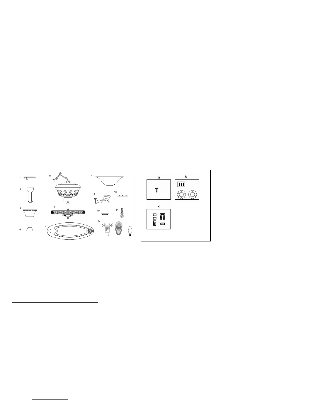
Unpacking Your Fan 2.
1. Mounting Plate (inside Canopy)
2. Downrod and Ball Assembly
(with hanger pin and locking pin
pre-attached)
3. Canopy
4. Decorative Motor Collar Cover
5. Fan Motor Assembly
6. Light Kit Assembly
7. Glass Shade
8. Blade Brackets (5)
(with blade bracket screws
pre-installed)
9. Blades (5)
10. Bottom Cover
11. Finial and Threaded Tube
12. Hand Unit/ Receiver
(a 12V battery included)
13. Extra 45-degree Canopy Bottom
Cover
a) Blade Attachment Hardware
(15 washer head screws)
b) Mounting Hardware
(1 plastic gasket, 1 metal gasket, 3
screws & lock-washers)
c) Electric Hardware & Balancing
Kit
(3 plastic wire connectors, blade
balancing kit)
d) Mounting Hardware (2 extra
mounting screws #10-32 for outlet
box)
IMPORTANT
PLEASE REMOVE RUBBER STOPS FROM THE FAN
MOTOR BEFORE INSTALLING BLADES OR TESTING
MOTOR.
14. Bulbs (2)
14
Tools Required
Phillips screw driver, straight slot
screw driver, adjustable wrench, step
ladder, and wire cutters.
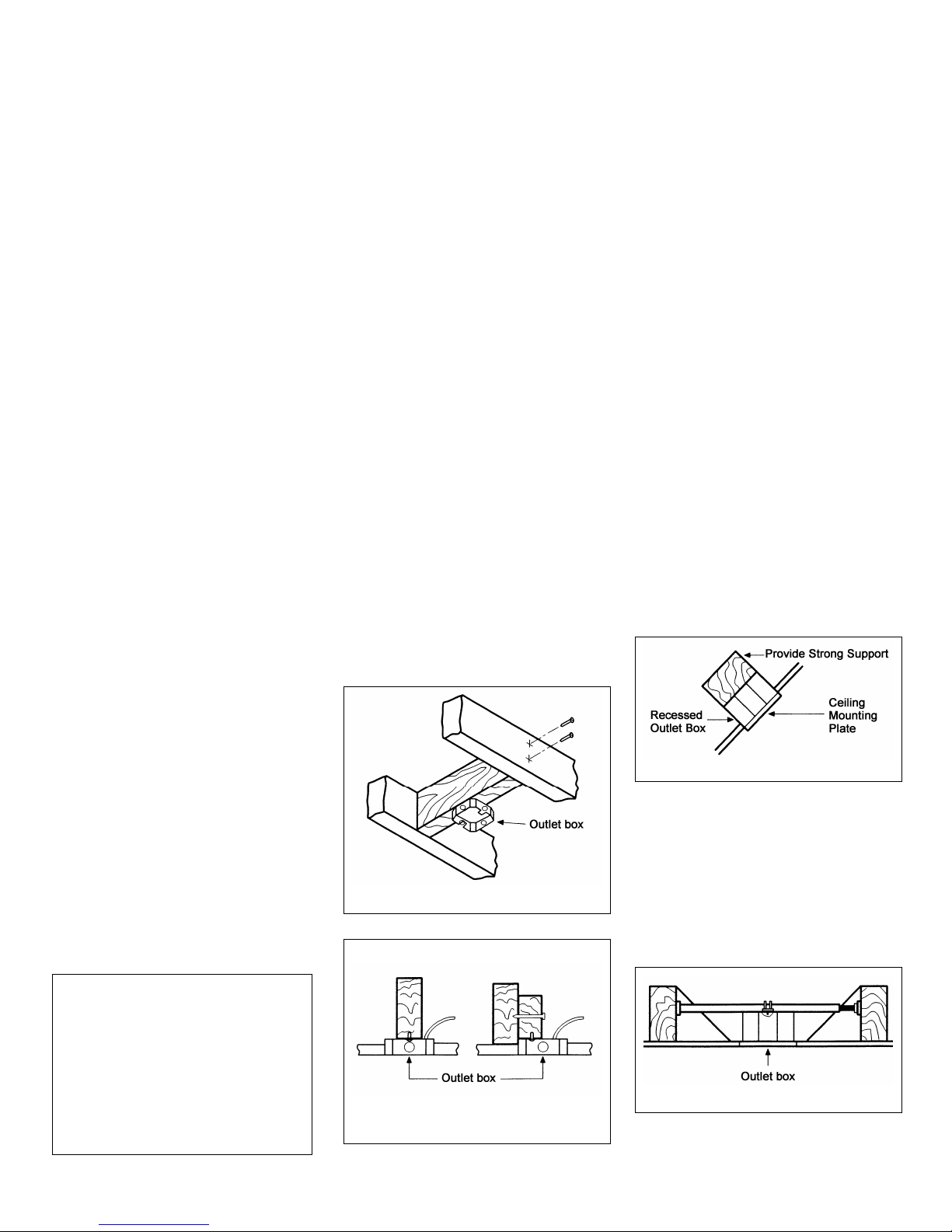
Mounting Options
If there isn't an existing mounting box,
then read the following instructions.
Disconnect the power by removing
fuses or turning off circuit breakers.
Secure the outlet box directly to the
building structure. Use appropriate
fasteners and building materials. The
outlet box and its support must be able
to fully support the moving weight of
the fan (at least 50 lbs.). Do not use
plastic outlet boxes.
WARNING
TO REDUCE THE RISK OF FIRE,
ELECTRIC SHOCK, OR OTHER
PERSONAL INJURY, MOUNT FAN ONLY TO
AN OUTLET BOX MARKED OF 22.7 KGS
(50 LBS) OR LESS AND USE THE
MOUNTING SCREWS PROVIDED WITH
THE OUTLET BOX. OUTLET BOXES
COMMONLY USED FOR THE SUPPORT OF
LIGHTING FIXTURES MAY NOT BE
ACCEPTABLE FOR FAN SUPPORT AND
MAY NEED TO BE REPLACED. CONSULT A
QUALIFIED ELECTRICIAN IF IN
DOUBT.
Figures l, 2, and 3 are examples of
different ways to mount the outlet box.
Figure 1
Figure 2
Figure 3
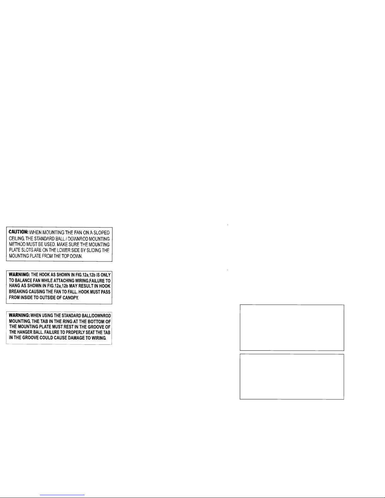
Note: You may need a longer
down-rod to maintain proper blade
clearance when installing on a steep,
sloped ceiling. The maximum angle
allowable is 45
degrees. Note: For
mounting angles between 20-45
degrees, please replace the canopy
bottom cover installed on the bottom
of the canopy opening with the extra
45-degree canopy bottom cover
included.
Figure 4
To hang your fan where there is an
existing fixture but no ceiling joist,
you may need an installation hanger
bar as shown in Figure 4 (available at
your Thomasville Lighting Retailer).
3.Installing Your Fan
Hanging the Fan
REMEMBER to turn off the power.
Follow the steps below to hang your
fan properly.
NOTE: This ceiling fan is supplied
with two types of hanging assemblies;
the standard ceiling installation using
the ball/ downrod assembly mounting,
and the "close-to-ceiling" mounting.
The "close-to-ceiling" mounting is
recommended in rooms with less than
8-foot ceilings or in areas where
additional space is desired from the
floor to the fan blades. When using
standard downrod installation, the
distance from the ceiling to the bottom
of the fan blades will be approximately
13 inches. The "close-to-ceiling"
installation reduces the distance from
the ceiling to the bottom of the fan
blades to approximately 8 inches.
ST ANDARD CEILING MOUNTING
Note: For mounting angles between
20-45 degrees, please replace the
canopy bottom cover installed on the
bottom of the canopy opening with
the extra 45-degree canopy bottom
cover included.
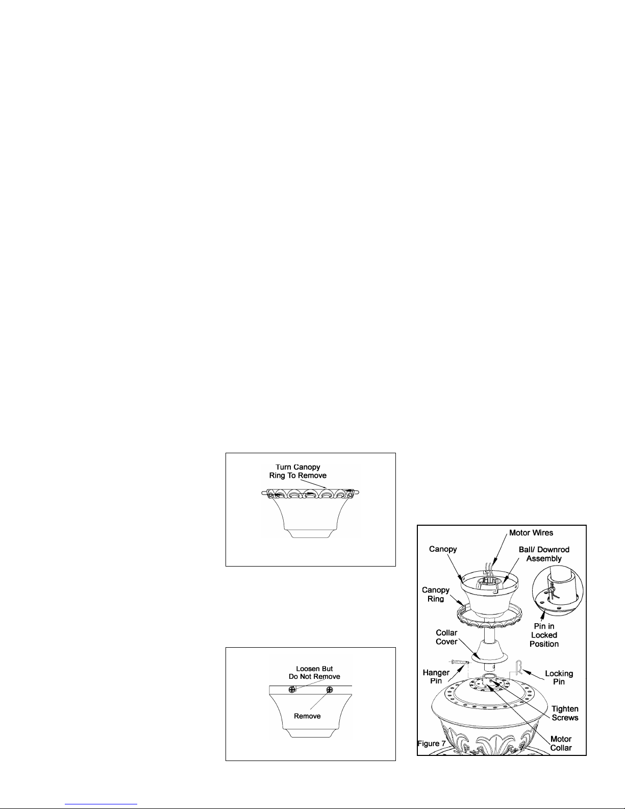
1. Remove the canopy ring from the
canopy by turning the ring to the right
until it unlocks (Figure5).
Figure 5
2. Remove the mounting plate from
the canopy by loosening the four
screws on the top of the canopy.
Remove the two non-slotted screws
and loosen the slotted screws. This will
enable you to remove the mounting
plate (Figure 6).
Figure 6
3. Remove the hanger pin and
locking pin from downrod assembly.
4. Route the wires exiting the top of
the fan motor through the decorative
motor collar cover then the canopy
ring. Make sure the slot openings are
on top. Route the wires through the
canopy and then through the
ball/downrod assembly (Figure 7).
5. Loosen, but do not remove, the set
screws on the collar on the top of the
motor housing.
4.
6. Align the holes at the bottom of
the downrod with holes in the collar on
top of the motor housing (Figure 7).
Carefully insert the hanger pin through
the holes in the collar and downrod. Be
careful not to jam the pin against the
wiring inside the downrod. Insert the
locking pin through the hole near the
end of the hanger pin until it snaps into
its locked position as noted in the
circle inset of Figure 7.
7. Re-tighten the set screws on the
collar on the top of the motor housing.
WARNING
FAILURE TO PROPERLY INSTALL
LOCKING PIN AS NOTED IN STEP 6
COULD RESULT IN FAN LOOSENING AND
POSSIBLY FALLING.
CLOSE-TO-CEILING
MOUNTING
1. Remove the canopy ring from the
canopy by turning the ring to the right
until it unlocks (Figure 5).
2. Remove the mounting plate from
the canopy by loosening the four
screws on the top of the canopy.
Remove the two non-slotted screws
and loosen the slotted screws. This
will enable you to remove the
mounting plate (Figure 6).
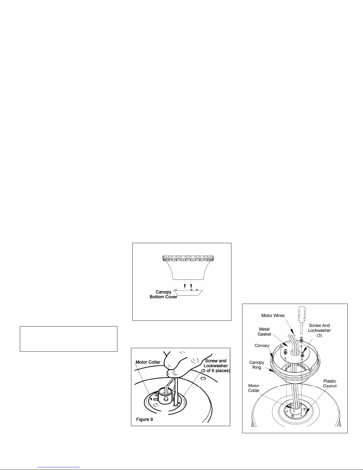
3. Remove the decorative canopy
bottom cover from the canopy by
depressing the three studs (Figure 8).
Figure 8
4. Remove three of the six screws and
lockwashers (every other one) securing
the motor collar to the top of the fan
motor housing (Figure 9).
5. Route the wires exiting the top of the
fan motor through the plastic gasket,
canopy ring, canopy and the metal
gasket, place the plastic gasket over the
remaining three screws, place the
canopy ring, canopy and the metal
gasket over the motor collar at the top
of the fan motor (Figure 10).
6. Align the three mounting screw holes
on the metal gasket with the holes on
the motor collar at the top of the fan
motor and fasten, using the three screws
and lockwashers provided with metal
gasket.
7. Tighten the three mounting screws
securely.
Figure 10
5.
Installing Fan to the
Electrical Box
THE OUTLET BOX AND
SUPPORT STRUCTURE MUST
BE SECURELY MOUNTED AND
CAPABLE OF RELIABLY
SUPPORTING A MINIMUM OF
50 POUNDS. USE ONLY UL
LISTED OUTLET BOXES
MARKED “ACCEPTABLE FOR
FAN SUPPORT OF 22.7 KGS (50
LBS) OR LESS”.
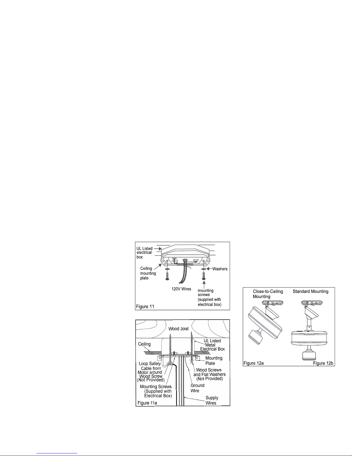
1. Pass the 120-volt supply wires
through the center hole in the ceiling
mounting plate as shown in Fig.11.
2. Install the ceiling mounting plate
on the electrical box by using the mounting screws provided with the electrical box.When using the close-to-ceiling
mounting, it is important that the mounting plate be level. If necessary, use leveling washers(not supplied)between the
mounting plate and electrical box. Note
that the flat side of the mounting plate is
toward the electrical box.(Fig.11)
3. Tighten the two screws on the electrical box securely.
6.
CONNECTING THE SAFETY
CABLE
a. Place the looped end of the safety
cable around the untightened wood
screw as shown in Figure 11a.
b. Tighten the wood screw securing
the safety cable.
CAUTION: In order to extend the
length of the safety cable, please use
braided steel cable of the same
thickness or greater and secure
according to local and national electric
codes. Please Consult a qualified
electrician if you are in doubt.
4. Carefully lift the fan assembly up to
the ceiling mounting plate and hang the
fan on the hook provided by utilizing
one of the holes at the outer rim of the
ceiling canopy.(Fig.12a,12b)
Making the Electrical
Connections
REMEMBER to disconnect the power.
If you feel that you do not have enough
electrical wiring knowledge or
experience, have your fan installed by a
licensed electrician.
Follow the steps below to connect the
fan to your household wiring. Use the
wire connecting nuts supplied with your
fan and supplied with remote control.
Secure the connectors with electrical
tape. Make sure there are no loose
strands or connections (Figure 13).
l. Connect both green wires from the
down-rod and mounting plate to the
bare copper (Ground) from the electrical
box.
2.
Connect the black wire (AC IN L)
from the receiver unit to the black wire
from the electrical box.
3. Connect the white wire (AC IN N)
from the receiver unit to the white wire
from the electrical box.
4. Connect the white wire (To Motor
N) from the receiver unit to the white
wire from the fan assembly.
5. Connect the black wire (To Motor
L) from the receiver to the black wire
from the fan assembly.
6. Connect the blue wire (For Light.)
from the receiver to the blue wire from
the fan.
After wires are connected, carefully
tuck them into the electrical box. Insert
the receiver unit into the mounting
plate; make sure the black antenna wire
sits on top of the receiver unit.
NOTE
THE FREQUENCIES ON YOUR RECEIVER
AND T
RANSMITTER HAVE BEEN PRESET AT
THE FACTORY, BEFORE INSTALLING THE
RECEIVER, MAKE SURE THE DIP SWITCHES
ON THE RECEIVER AND TRANSMITTER ARE
SET TO THE SAME FREQUENCY. THE DIP
SWITCHES ON THE TRANSMITTER ARE
LOCATED INSIDE THE BATTERY
COMPARTMENT.
WARNING
EACH WIRE NUT (WIRE CONNECTOR)
SUPPLIED WITH THIS FAN IS DESIGNED TO
ACCEPT UP TO ONE 12 GAUGE HOUSE WIRE
AND TWO WIRES FROM THE FAN. IF YOU
HAVE LARGER THAN 12 GAUGE HOUSE
WIRING OR MORE THAN ONE HOUSE WIRE
TO CONNECT TO THE FAN WIRING,
CONSULT AN ELECTRICIAN FOR THE
PROPER SIZE WIRE NUTS TO USE.
7.
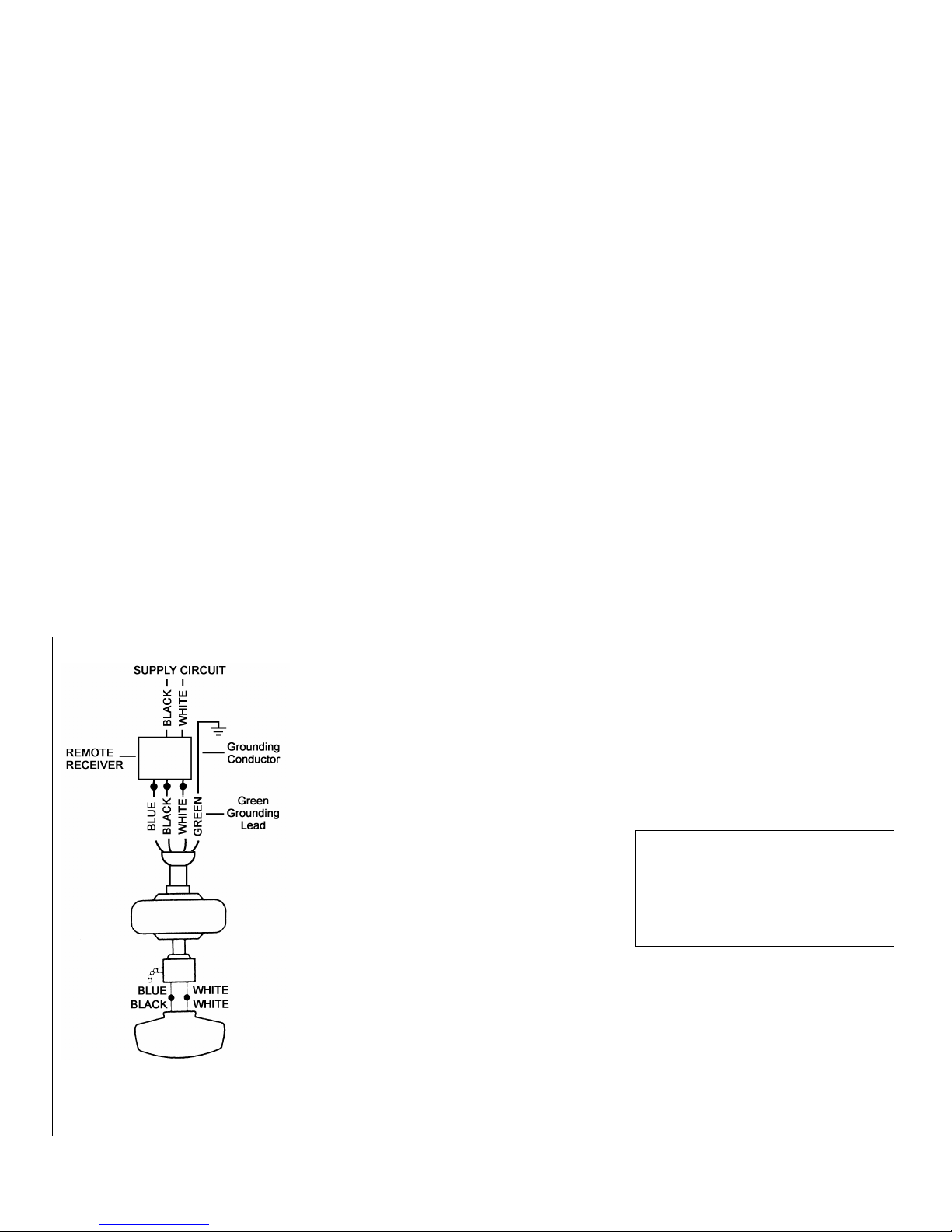
Figure 13
8.
Finishing the Fan
Installation
STANDARD CELING MOUNTING
1. Carefully lift the canopy up to the
mounting plate . Make sure the tab in
the ring at the bottom of the canopy is
properly seated in the groove in the
hanger ball. Align the locking slots of
the ceiling canopy with the two screws
in the mounting plate. Push up to
engage the slots and turn clockwise to
lock in place. Immediately tighten the
two mounting screws firmly.
2. Install the remaining two mounting
screws into the holes in the canopy and
tighten firmly.
3. Install the decorative canopy ring
by aligning the ring’s slots with the
screws in the canopy. Rotate the ring
counter-clockwise to lock in place.
4. You may now proceed to attaching
the fan blades
.
CLOSE-TO-CEILING MOUNTING
1. Carefully unhook the fan from the
mounting plate and align the locking
slots of the ceiling canopy with the two
screws in the mounting plate. Push up to
engage the slots and turn clockwise to
lock in place. Immediately tighten the
two mounting screws firmly.
2. Install the remaining two mounting
screws into the holes in the canopy and
tighten firmly.
3. Install the decorative canopy ring
by aligning the ring’s slots with the
screws in the canopy. Rotate the ring
counter-clockwise to lock in place.
4. You may now proceed to attaching
the fan blades.
WARNING
LOCKING SLOTS OF CEILING
CANOPY ARE PROVIDED ONLY AS
AN AID TO MOUNTING. DO NOT
LEAVE FAN ASSEMBLY UNATTENDED
UNTIL ALL FOUR CANOPY SCREWS
ARE ENGAGED AND FIRMLY
TIGHTENED.
 Loading...