


Muffle Furnace
OPERATION MANUAL
AND PARTS LIST
Series 1285
Model Voltage Control Display
5300A20/F48025-TS 120V Single Setpoint Model °C
5300A25/F48025-80-TS 120V 8 Setpoint Programmable Model °C
LT1285X5 • 5/12/09
with OTP
with OTP

Table of Contents
Safety Information ..............................................................................................................................................3
Alert Signals..................................................................................................................................................3
Warnings ......................................................................................................................................................3
Introduction..........................................................................................................................................................5
Intended Use ................................................................................................................................................5
General Usage..............................................................................................................................................5
Principles of Operation ................................................................................................................................5
General Specifications ........................................................................................................................................6
Models 5300A20/F48025-TS and 5300A25/F48025-80-TS ........................................................................6
Environmental Conditions ............................................................................................................................7
Unpacking ..........................................................................................................................................................8
Installation ..........................................................................................................................................................9
Site Selection................................................................................................................................................9
Electrical Connections ..................................................................................................................................9
Operation, All Models ........................................................................................................................................10
Power Switch ..............................................................................................................................................10
Cycle Light ..................................................................................................................................................10
Door Safety Switch ....................................................................................................................................10
Single Setpoint Model with OTP ......................................................................................................................11
Single Ramp & Dwell ........................................................................................................................................15
8 Segment Programmable Models with OTP....................................................................................................17
Furnace Loading ..............................................................................................................................................31
Preventative Maintenance ................................................................................................................................32
General Cleaning Instructions ....................................................................................................................32
Troubleshooting ................................................................................................................................................33
Maintenance and Servicing ..............................................................................................................................35
To Replace a Heating Element ..................................................................................................................35
To Replace a Chromel/Alumel Thermocouple ............................................................................................36
To Replace Door Switches (Micro-Switch) ................................................................................................37
To Realign Door Switches (Micro-Switch) ..................................................................................................37
To Replace the Controller ..........................................................................................................................38
Replacement Parts............................................................................................................................................39
Single Setpoint Models with OTP ..............................................................................................................39
8 Segment Programmable Models with OTP ............................................................................................39
Ordering Procedures ..................................................................................................................................39
Wiring Diagrams................................................................................................................................................40
Warranty Repair and Service ............................................................................................................................44
2
Alert Signals
Warning
Warnings alert you to a possibility of personal injury.
Caution
Cautions alert you to a possibility of
damage to the equipment.
Note
Notes alert you to pertinent facts and
conditions.
Safety Information
This manual contains important operating and safety information. You must carefully read and understand the contents of this manual prior to the use of this furnace.
Your Thomas Scientific 5300A20/F48025-TS or
5300A25/F48025-80-TS Muffle Furnace has been
designed with function, reliability and safety in mind. It is
your responsibility to install it in conformance with local
electrical codes. For safe operation, please pay attention to
the alert signals throughout the manual.
Warnings
To avoid electrical shock, this furnace must:
1. Use a properly grounded electrical outlet of correct voltage and current handling capacity.
2. Be disconnected from the power supply prior to
maintenance and servicing.
Hot Surface
Hot surfaces alert you to a possibility of
personal injury if you come in contact
with a surface during use or for a period
of time after use.
3. Have the door switch operating properly.
To avoid personal injury:
1. Do not use in the presence of flammable or combustible materials; fire or explosion may result.
This device contains components which may
ignite such material.
2. Caution: Hot Surface - Avoid Contact. To avoid
burns, do not touch the exterior or interior surfaces of this furnace during use or for a period of
time after use.
3. Always wear safety glasses or a safety shield and
high temperature gloves when loading or unloading the furnace. Long sleeved, fire retardant clothing and a fire retardant apron is also recommended.
4. Refer servicing to qualified personnel.
3

SAFETY INFORMATION
Warning
Refer servicing to qualified personnel.
Warning
This warning is presented for compliance with California
Proposition 65 and other regulatory agencies and only applies
to the insulation in this product. This product contains refractory ceramic, refractory ceramic fiber or fiberglass insulation,
which can produce respirable dust or fibers during disassembly. Dust or fibers can cause irritation and can aggravate preexisting respiratory diseases. Refractory ceramic and refractory
ceramic fibers (after reaching 1000°C) contain crystalline silica,
which can cause lung damage (silicosis). The International
Agency for Research on Cancer (IARC) has classified refractory ceramic fiber and fiberglass as possibly carcinogenic (Group
2B), and crystalline silica as carcinogenic to humans (Group 1).
The insulating materials can be located in the door, the hearth
collar, in the chamber of the product or under the hot plate top.
Tests performed by the manufacturer indicate that there is no
risk of exposure to dust or respirable fibers resulting from operation of this product under normal conditions. However, there
may be a risk of exposure to respirable dust or fibers when
repairing or maintaining the insulating materials, or when otherwise disturbing them in a manner which causes release of dust
or fibers. By using proper handling procedures and protective
equipment you can work safely with these insulating materials
and minimize any exposure. Refer to the appropriate Material
Safety Data Sheets (MSDS) for information regarding proper
handling and recommended protective equipment. For additional MSDS copies, or additional information concerning the
handling of refractory ceramic products, please contact the
Customer Service Department at Thomas Scientific at 1-800345-2100.
4

Caution
Do not exceed operating temperatures
shown in “General Specifications.”
Exceeding these limits will result in
severely reduced element life.
Introduction
Intended Use
The 5300A20/F48025-TS or 5300A25/F48025-80-TS
furnace is a general purpose laboratory and heat treating furnace. For optimum element life, Thomas
Scientific recommends observing these temperature
ranges: from 100°C (212°F) to 1093°C (2000°F) continuous use or from 1093°C (2000°F) to 1200C (2192°F)
for intermittent use. Continuous use is operating the
furnace for more than 3 hours and intermittent use is
operating the furnace for less than 3 hours.
All furnaces consist of: 1) a vented heating chamber;
2) a temperature controller; and 3) a door safety switch
for operator safety.
General Usage
Do not use this product for anything other than its
intended usage.
Principles of Operation
The furnace chamber is heated by open coil electric
resistance elements and is insulated with ceramic fiber
insulation. The controller is located under the furnace
chamber and is well insulated from the heat generated
in the furnace chamber. A door safety switch removes
power to the heating elements whenever the furnace
door is opened. The temperature is controlled by one
of three types of controllers.
5

General Specifications
Models 5300A20/F48025-TS and 5300A25/F48025-80-TS
Dimensions in Inches (cm):
Chamber: 7 (17.8) W x 5 (12.7) H x 10 (25.4) D
Overall: 13.25 (33.7) W x 19 (48.3) H x 19.5 (49.5) D
Weight: 56 lb. (25.4 kg)
Electrical Ratings:
Volts: 120
Amps: 14.5
Watts: 1800
Frequency: 50/60
Phase: 1
Temperature:
Operating Range: 2000°F (1093°C) continuous
2192°F (1200°C) intermittent
6

GENERAL SPECIFICATIONS
Environmental Conditions
Operating: 17°C to 27°C; 20% to 80% relative humidity, non-condensing. Installation Category II
(overvoltage) in accordance with IEC 664. Pollution degree 2 in accordance with IEC 664.
Altitude Limit: 2,000 meters.
Storage: -25°C to 65°C; 20% to 80% relative humidity
7

Unpacking
1. Visually check for any physical damage
to the shipping container.
2. Inspect the equipment surfaces that are
adjacent to any damaged area.
3. Open the furnace door and remove the
packing material from inside the furnace
chamber.
4. Vacuum the chamber prior to use to
remove the insulation dust due to shipment. (The 5300A20/F48025-TS and
5300A25/F48025-80-TS furnaces are
supplied with one ceramic shelf.)
5. Retain the original packaging material if
reshipment is foreseen or required.
8

Caution
Be sure ambient temperature does not
exceed 40°C (104°F). The recommended
ambient temperature is 17°C - 27°C.
Ambients above this level may result in
damage to the controller.
Caution
Allow at least six inches of space
between the furnace and any combustible
surface. This permits the heat from the
furnace case to escape so as not to create a possible fire hazard.
Installation
Site Selection
Install furnace on a sturdy surface and allow adequate
space for ventilation.
Electrical Connections
The electrical ratings are located on the specification
plate on the back of the furnace. Consult Thomas
Scientific if your electrical service is different than
those listed on the specification plate. Be sure the front
power switch is in the OFF position before connecting
the furnace to your electrical supply.The
5300A20/F48025-TS or 5300A25/F48025-80-TS furnaces are supplied with a power cord rated at 120V,
15 amps.
Warning
To avoid electrical shock, this furnace
must always use a properly grounded
outlet of correct voltage and current handling capacity.
9
Operation, All Models
Warning
To avoid personal injury do not use in the
presence of flammable or combustible
chemicals; fire or explosion may result.
This device contains components which
may ignite such materials.
Hot Surface
Caution: Avoid Contact. To avoid burns,
this furnace must not be touched on the
exterior or interior surfaces during use or
for a period of time after use.
Warning
Always wear safety glasses or a safety
shield and high temperature gloves when
loading or unloading the furnace. Long
sleeved, fire retardant clothing and a fire
retardant apron is also recommended.
Power Switch
Both the ON/OFF power switch and the digital display
will illuminate when power is switched ON. The furnace will begin to heat to its controller's current setpoint. (See the instructions for your type of controller
for information on checking and setting the setpoint.)
Cycle Light
The amber cycle light will illuminate whenever the
power is being applied to the heating elements. The
cycle light will turn on and off as the furnace reaches
the setpoint.
Door Safety Switch
The door safety switch removes power from the heating elements when the door is opened. Open and
close the door a few times; note that the amber
CYCLE light will switch off when the door is opened.
If this condition is not true, consult the
Troubleshooting section before proceeding. This
check must be done when the furnace is heating and
the cycle light is illuminated.
Warning
To avoid electrical shock, the door safety
switch must be operating properly.
10
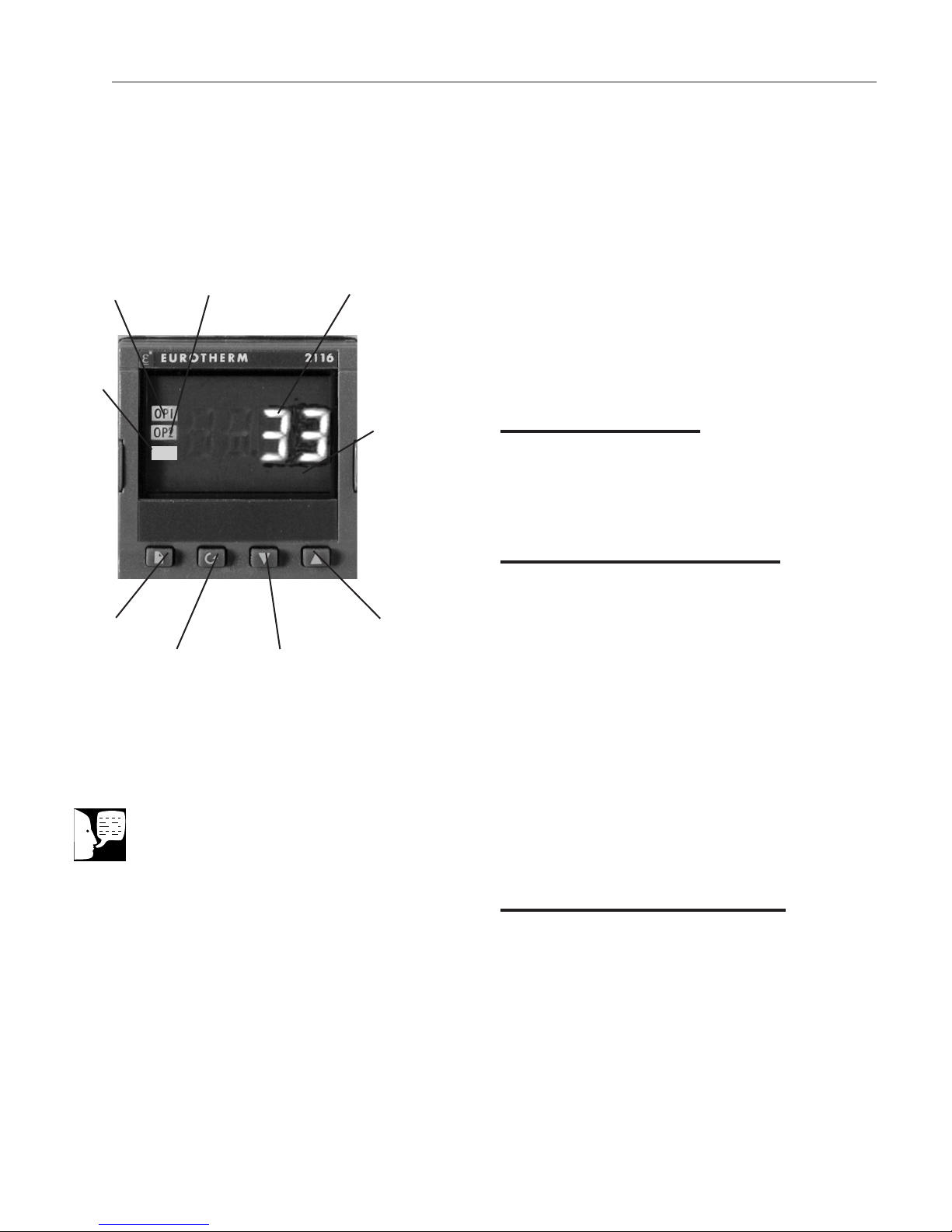
Single Setpoint Model w/OTP
Output 1
Manual
AN
M
PAGE
Button
Single Setpoint Models
SCROLL
Button
Output 2
DOWN ARROW
Button
Temperature
Display
Display
Window
UP ARROW
Button
The single setpoint model w/ OTP furnace controller is a single setpoint controller which provides a
single digital display to indicate the current chamber
temperature or setpoint temperature. This temperature controller features sensor break protection, selftuning capability and over temperature protection
(OTP) with an additional OTP relay device.
Basic Operation
When the controller is turned ON it will perform a
short self-test and then display the measured value
(process value) in the HOME DISPLAY.
Buttons and Indicators
OP1 (Output 1): Illuminates when the logic output is
ON.
OP2 (Output 2): Illuminates when the relay output is
ON (will go out during an alarm situation).
PAGE button: Allows you to select a new list of
parameters.
Note
If at any time you want to return to the
HOME DISPLAY, simultaneously press
the PAGE and SCROLL buttons.
SCROLL button: Allows you to select a parameter
within a list of parameters.
DOWN button: Allows you to decrease a value.
UP button: Allows you to increase a value.
To View or Change the
Setpoint
To view the setpoint, press and release the UP or
DOWN buttons. If you want to change the setpoint,
continue pressing until the desired setpoint value is
displayed and then release the button. A few seconds
after the button is released, the controller will accept
the new value and revert to the HOME DISPLAY.
11

SINGLE SETPOINT MODEL W/OTP
To View the Display Units
From the HOME DISPLAY press the SCROLL button. The
display will show the temperature units in °C/F/K and then
return to the HOME DISPLAY. (Call Customer Service if you
require a different temperature unit.)
To View the % Output Power
From the HOME DISPLAY press the SCROLL button twice.
Press and release the UP or DOWN button to view the %
output power. This value is a read-only value and cannot be
changed.
Controller Parameters
Home display
°C: Temperature units in Celsius. Temperature units can not
be changed without entering the configuration. Contact
Customer Service if a different temperature unit is required.
OP: % output power demand.
IdHi: Deviation high alarm. Factory preset to 50.
AL List (Alarm List)
IdHi: Deviation high alarm. Factory preset to 50.
3FSL: Full scale low alarm. Factory preset to -99°C.
Cannot be adjusted by end users.
Atun List (Autotune List)
tunE: One-shot autotune enable.
Pid List (Proportional, Integral, Derivative)
Pb: Proportional band (in display units). Factory preset to 5.
12
ti: Integral time in seconds. Factory preset to 0.48.
td: Derivative time in seconds. Factory preset to 0.8.
ACCS List Code: Access code (Code needed to enter or
change the other configuration parameters which are not
normally accessible.) Not accessible.

SINGLE SETPOINT MODEL W/OTP
Note
The following alarm messages are factory default settings and may vary if you
have changed the configuration of your
controller:
IDHi: = 50°C
2FSH = 1225°C
Alarms
The controller will flash an alarm message in the home
display if an alarm condition is detected.
2FSH: Measured value full scale high alarm. The full
scale high alarm is for furnace protection. It cannot be
accessed from the user list.
IdHi: Measured value deviation high alarm. The deviation alarm is factory preset at 50°C. If the chamber temperature rises to 50°C above the setpoint temperature,
this error condition will alert end users. The furnace will
continue to control temperature at the alarm setpoint,
which was defined as 50°C above the setpoint. End
users must power off the furnace and contact Customer
Service for troubleshooting assistance. Do not reset this
alarm below 20°C at any time.
S.br: Sensor Break: check that sensor is connected correctly.
L.br: Loop Break: check that the heating circuits are
working properly.
Ld.F: Heater Circuit Fault: indication of either an open or
short solid sate relay, a blown fuse, missing supply or
open circuit heater.
Sensor Break Protection
This controller provides sensor break protection in the
event the thermocouple opens. If an open thermocouple
condition occurs, the digital display will blink “S.br” and
the power to the heating element will be shut OFF (Cycle
light will extinguish).
Over-Temperature Protection
(OTP)
The OTP will be in effect during any alarm condition
when the temperature of the furnace has deviated
beyond the limit. The “Deviation High” alarm is the only
alarm value which can be changed. To change it, press
the SCROLL button until “IdHi” appears on the display.
13

SINGLE SETPOINT MODEL W/OTP
Note
Furnace must be at ambient
temperature before starting a tune.
Press the UP or DOWN button to select the OTP value
you desire. We recommend a value of 20° above your
working temperature to provide protection for your
workload.
In addition to over-temperature protection, units containing a single setpoint controller w/OTP feature a
mechanical OTP relay device which disconnects power
from the elements in an alarm condition (only in furnaces with OTP relay).
Tuning
This controller incorporates a self-tuning feature which
determines the optimum control parameters for the
best temperature accuracy with your load and setpoint.
Use this feature the first time you use your furnace and
each time you change either your setpoint or the type
of load you are heating. Thomas Scientific recommends you use this feature to provide the best temperature accuracy the controller can attain. To use the tuning feature:
1. Adjust the setpoint to your desired value.
14
Note
“Stat” and “Sp.rr” in Sp list must be
set to OFF or “tunE” will not initiate.
Note
Tune has completed when “tunE”
stops flashing on display.
2. Press the PAGE button until display reads,
“Atun.”
3. Press the SCROLL button. Display will read,
“tunE.”
4. Press the UP or DOWN button to select, “on.”
5. Simultaneously press the PAGE and
SCROLL buttons to return to the HOME DISPLAY. The display will alternately flash
between “tunE” and the HOME DISPLAY
while tuning is in progress.
6. The controller will then turn the heating on
and off to induce an oscillation. When the
measured value reaches the required setpoint
the first cycle will end.
7. Tuning will be complete after two oscillation
cycles and then the tuner will turn itself off.
8. Normal control function will resume after the
controller calculates tuning parameters.

Mode 1 (Opt. 1)
Single Ramp & Dwell
Functions
This type of controller has single ramp and dwell programming capabilities. The Ramp and Dwell can be configured
to five different modes.
1. Mode 1 (Opt. 1) is a Ramp (if needed) to the
Setpoint temperature, a Dwell, and then a cool
down.
2. Mode 2 (Opt. 2) is the same as mode 1, except
the controller continues to heat at the Setpoint
after the Dwell has completed. (This mode does
not cool down.)
3. Mode 3 (Opt. 3) is the same as mode 1, except
the Dwell time includes the Ramp (if needed).
Mode 2 (Opt. 2)
Mode 3 (Opt. 3)
Mode 4 (Opt. 4)
4. Mode 4 (Opt. 4) is the same as mode 2, except
the Dwell time includes the Ramp (if needed).
5. Mode 5 (Opt. 5) is a Dwell (delay time) before the
controller Ramps (if needed) to the Setpoint temperature.
Program Overview
• A program mode can be set by changing the
“tm.OP” variable to “Opt. 1, Opt. 2, Opt. 3, Opt. 4,
or Opt. 5.
• A Ramp rate may be set by changing the “SPrr”
variable to a value. The Ramp rate units are in
degrees per minute.
• The Dwell time can be set by changing the
“dwEll” variable to the desired value. Dwell time
units are in minutes.
• The program Status can be set by changing the
“StAt” variable to “run” or “oFF.” This variable will
start or stop the program.
Mode 5 (Opt. 5)
15

SINGLE RAMP & DWELL
Note
The program must be stopped and
the controller must be displaying the
actual temperature before beginning
the Setup.
Program Setup
1. Press the PAGE button until the “SP” is displayed.
2. Press the SCROLL button once, “SPrr” (Ramp
Rate) will be displayed, set the desired Ramp rate
with the UP or DOWN buttons, if the ramp to setpoint feature is needed. If the Ramp rate is not
needed, then set to “OFF” with the UP or DOWN
buttons.
3. Press the SCROLL button once, “tm.OP” (Ramp &
Dwell mode) will be displayed, select the desired
mode with the UP or DOWN buttons. (Opt. 1, Opt.
2, Opt. 3, Opt. 4, Opt. 5)
4. Press the SCROLL button once, “dwEll” will be displayed, set the desired Dwell time with the UP or
DOWN buttons. (Dwell in minutes.)
5. Press the PAGE button until the Actual temperature is displayed.
Running the Program
1. Press the SCROLL button until “StAt” is displayed,
set to “run” with the UP or DOWN buttons.
2. Press the PAGE button to display Actual temperature.
Stopping the Program
Press the SCROLL button until “StAt” is displayed, set to
“oFF” with the UP or DOWN buttons.
Clearing the Flashing End
Press the PAGE and SCROLL buttons at the same time.
16
Verifying a Running Program
Press the SCROLL button until “StAt” is displayed. The display will show “run” if the program is running, or “oFF” if it is
not running. Press the PAGE button to display Actual temperature.

AUTO/MAN
Button
8 Segment Programmable
Model w/OTP
The 8 segment programmable controller consists of
Note
The controller will return to the HOME
DISPLAY if left idle for more than a few
seconds.
Note
Once the desired parameter has been
selected, depressing either the UP or
DOWN button will change the parameter
value. In all cases, the value shown on
the display is the current working value of
that parameter.
Output 1
Display
Window
a microprocessor based three-mode PID
(Proportional, Integral, Derivative), programmable
temperature controller with over-temperature protection and appropriate output switching devices to control the furnace. The digital readout continuously displays chamber (upper display) and setpoint (lower
display) temperatures unless the SCROLL or PAGE
button is depressed. The programmable controller
can be used as a single setpoint controller or as a
programmable controller. The 8 segment digital model
enables eight segments of programming.
Basic Operation
When the controller is turned ON, it will perform a
short self-test and then change to the HOME DISPLAY. The HOME DISPLAY shows the measured
temperature (process value) in the upper display and
the desired value (setpoint) in the lower display.
Upper
Display
Lower
Display
RUN/HOLD
UP ARROW
PAGE
Button
8 Segment Programmable Model with OTP
SCROLL
Button
DOWN ARROW
Button
Button
Button
To Change the Setpoint
If you want to change the setpoint, press the UP or
DOWN button until the desired setpoint value is displayed in the lower display and then release the button.
To View Display Units
From the HOME DISPLAY press the SCROLL button.
The display will briefly show the temperature units in
°C/F/K and then return to the HOME DISPLAY. (If you
require a different temperature unit call Thomas
Scientific Customer Service.)
To View the % Output Power
From the HOME DISPLAY press the SCROLL button
twice. This value is a read-only value and cannot be
changed.
17

8 SEGMENT PROGRAMMABLE MODEL W/OTP
Buttons and Indicators
OP1 (Output 1): illuminates when the heating output of
the temperature controller is on.
AUTO/MAN: (Auto/Manual Mode): when the controller is in the automatic mode the output automatically
adjusts to keep the temperature or process value at the
setpoint. The “AUTO” light will illuminate. The manual
mode has been disabled through factory configuration.
Attempts to operate in manual mode are not recommended.
RUN/HOLD (Run/Hold button):
• Starts a program when pressed once—RUN
light illuminates.
• Holds a program when pressed again—
HOLD light illuminates.
• Cancels hold and continues running when
pressed again—HOLD light is off and RUN
light illuminates.
• Exits a program when the button is held down
for two seconds—RUN and HOLD lights are
off.
• At the end of a program the RUN light will
flash.
• During holdback the HOLD light will flash.
PAGE button: allows you to select a list in the user or
configuration mode.
SCROLL button: allows you to select a parameter
within a list in the user configuration mode.
UP button: allows you to increase the value in the
lower display.
18
DOWN button: allows you to decrease the value in the
lower display.

8 SEGMENT PROGRAMMABLE MODEL W/OTP
Controller Parameters
Home Display
°C: measured temperature in Celsius. Temperature units
can not be changed without entering the configuration.
Contact Customer Service if a different temperature unit
is required.
OP: % output power demand; displayed in lower display
(cannot be changed).
C.id: Controller identification number.
IdHi: Deviation High Alarm. Factory preset to 50.
tunE: One-shot autotune enable.
run LiSt (Program Run List)
PrG (Program): Currently running program (only used on
4x16 programmable models)
StAt (Status): Displays the program status [OFF, run
(running active program), hoLd (program on hold), HbAc
(waiting for process to catch up), End (program completed)] in the lower display. The controller will default to
“OFF.”
FASt (Fast): Fast run through program (no/YES). The
controller will default to “no.”
SEG.d (Segment): Flash active segment type in the
lower display of the home display (no/YES). The controller will default to “no.”
ProG LiSt (Program Edit List)
Hb (Holdback): Press the UP or DOWN ARROW to
select the holdback type [OFF (disables holdback), Lo
(deviation low holdback), Hi (deviation high holdback) or
bAnd (deviation band holdback)] for the entire program.
The controller will default to “OFF.”
Hb.U (Holdback Units): Press the UP or DOWN
ARROW to select the holdback value (in display units).
19

8 SEGMENT PROGRAMMABLE MODEL W/OTP
rmP.U (Ramp Units): Press the UP or DOWN ARROW
to toggle between ramp units (SEc, min or Hour).
Controller will default to “SEc.”
dwL.U (Dwell Units): Press the UP or DOWN ARROW
to toggle between dwell units (SEc, min or Hour).
Controller will default to “SEc.”
Cyc.n (Cycle Number): Press the UP or DOWN
ARROW to set the number of program cycles (1 to 999
or cont). The controller will default to “cont.”
SEG.n (Segment Number): Press the UP or DOWN
ARROW to select the segment number (1-8).
tYPE (Type of Segment): Press the UP or DOWN
ARROW to select the segment type [End (end of program), rmP.r = ramp rate (ramp to a specified setpoint at
a set rate), rmp.t = ramp time (ramp to a specified temperature in a set time), dwEll (to maintain a constant
temperature for a set time), StEP (climb instantaneously
from current to specified temperature). The controller will
default to “End.” Other parameters used with tYPE
include; tGt target setpoint), Rate (rate of temperature
increase) and dur (time to target setpoint or time to
dwell).
20
End.t (End Type): End segment type: dwELL (dwell continuous), rSEt (reset) and S OP (End Segment Output
power level.
AL LiSt (Alarm List)
IdHi: Deviation High Alarm. Factory preset to 50.
Atun LiSt (Autotune List)
tunE: One-shot autotune enable. Resets the PID values
automatically.
drA: Adaptive tune enable. Monitors the process variable
and resets the PID values if the process variable
exceeds the trigger level.
drA.t: Adaptive tune trigger level in display units. Range
= 1 9999.

8 SEGMENT PROGRAMMABLE MODEL W/OTP
Pid LiSt
G.SP (Gain Setpoint): Is the temperature at which
the controller switches from the (SEt1) PID values to
the (SEt 2) PID values.
Pb: Proportional band in display units. (SEt 1)
ti: Integral time in seconds. (SEt 1)
td: Derivative time in seconds. (SEt 1)
Pb2: Proportional band. (SEt 2)
ti2: Integral time in seconds. (SEt 2)
Note
The following alarm messages are factory
default settings and may vary if you have
changed the configuration of your
controller:
IDHi: = 50°C
2FSH = 1225°C
td2: Derivative time in seconds. (SEt 2)
ACCS LiSt (Access List)
Access Code (Code needed to enter or change the
other configuration parameters which are not normally
accessible.) Not accessible.
Alarms
The controller will flash an alarm message in the
home display if an alarm condition is detected.
IdHi: PV deviation high alarm. Factory preset at
50°C.
2FSH: PV full scale high alarm. Factory preset at
1225°C. The full scale high alarm is for furnace protection. The parameter is not accessible from the user
list.
S.br: Sensor break: check that sensor is connected
correctly.
L.br: Loop Break: Check that the heating circuits are
working properly.
21

8 SEGMENT PROGRAMMABLE MODEL W/OTP
Sensor Break Protection
This controller provides sensor break protection in the
event the thermocouple opens. If an open thermocouple
condition occurs, the digital display will Blink “S.br” and
the power to the heating element will be shut OFF (Cycle
light will extinguish).
Over-Temperature Protection
(OTP)
The OTP will be in effect during any alarm condition
when the temperature of the furnace has deviated
beyond the limit. The “Deviation High” alarm is the only
alarm value which can be changed. To change it, press
the SCROLL button until “idHi” appears on the display.
Press the UP or DOWN button to select the OTP value
you desire. We recommend a value of 20° above your
working temperature to provide protection for your workload.
22
To Operate the Controller as a
Single Setpoint Controller
1. Switch the power switch to the “ON” position.
The setpoint temperature presently set in the
controller will appear in the lower display. (The
upper display indicates the actual chamber temperature.)
2. To change the setpoint, press the UP or DOWN
button until the desired setpoint value is displayed; then release the button.
3. From the home list, use the page key (press
and release) to access the run list.
4. From the run list, use the scroll key (press and
release) to view “StAt.” Ensure “StAt” is set to
off. Use up or down arrow to select off if necessary.
5. The furnace will begin to heat if the new setpoint temperature is higher than the present
chamber temperature.

8 SEGMENT PROGRAMMABLE MODEL W/OTP
Programming the Controller
The controller is capable of varying temperature or process
value with time through programming. A program is stored
as a series of segments and can be run once, repeated a
set number of times or run continuously. To create a customized program using the controller parameters listed
under “Controller Parameters” at the beginning of this section, follow the procedures outlined in the proceeding sections of this manual. All programming is accomplished in the
ProG list.
Hb: Holdback
Step 1 in programming the controller is to set the holdback
feature. Holdback consists of a value and a type. If the
measured value lags behind the setpoint by an undesirable
amount during a ramp or dwell, the holdback feature can be
used to freeze the program at its current state (the HOLD
light will flash). The program will resume when the measured value comes within the holdback value.
Holdback can be set to 1 of 4 settings. They are as follows:
1) OFF: holdback is disabled.
2) Lo (Deviation Low Holdback): holds the program back
when process variable deviates below the setpoint by more
than the holdback value.
3) Hi (Deviation High Holdback): holds the program back
when process variable deviates above the setpoint by more
than the holdback value.
4) bAnd (Deviation Band Holdback): combines the features of the high and low deviation holdback in that it holds
the program back when the process variable deviates
above or below the setpoint by more than the holdback
value.
To set the holdback type when programming the controller:
1. Press the PAGE button until you reach the program list (ProG LiSt).
2. Press the SCROLL button until display reads,
“Hb.”
23

8 SEGMENT PROGRAMMABLE MODEL W/OTP
Note
The value set in this parameter is always
for the entire program.
3. Press the UP or DOWN button to toggle between
“bAnd, Hi, Lo and OFF.”
If you choose to activate the holdback feature for your program by selecting Lo, Hi or bAnd, you will also need to set
the holdback value.
Hb U: Holdback Value
Step 2 in programming the controller is to set the Holdback
Value. If you donʼt activate the holdback feature, move on to
“mP.U: Setting Ramp Units”
To set the holdback value:
1. Press the PAGE button until you reach the program list (ProG LiSt).
Note
The holdback value should never be set
less than 10.
Note
The time units you set for the ramp and
dwell apply for the entire program.
2. Press the SCROLL button until display reads,
“Hb.U.”
3. Press the UP or DOWN button to enter a holdback
value.
rmP.U: Setting Ramp Units
Step 3 in programming the controller is defining ramp rate
units. Ramp units are time units which are used in “rmP.r”
segments (ramp to a setpoint at degrees per second, minute
or hour) and “rmP.t” segments (ramp to setpoint in a specific
amount of time). See “Setting the Segment Type” for an
explanation on how to set a ramp segment.
To set the ramp rate units:
1. Press the PAGE button until you reach the program list (ProG LiSt).
2. Press the SCROLL button until display reads,
“rmP.U.”
3. Press the UP or DOWN button to toggle between
seconds, minutes and hours.
24

8 SEGMENT PROGRAMMABLE MODEL W/OTP
dwL.U: Setting Dwell Units
Step 4 in programming your controller is defining dwell
units. Dwell units are time units which are used in
“dwELL” segments (amount of time to remain at a specific temperature ). See “Setting the Segment Type” for an
explanation on how to set a dwell segment.
To set the dwell units:
1. Press the PAGE button until you reach the program list (ProG LiSt).
2. Press the SCROLL button until display reads,
“dwL.U.”
3. Press the UP or DOWN button to toggle
between seconds, minutes and hours.
Note
The program ramp rate is designed to
reduce the heatup rate or cooling rate
that the furnace normally exhibits.
When not using this feature, the furnace will operate at its maximum
heating and cooling capability.
CYC.n: Setting the Number of Cycles
Step 5 in programming the controller is to define the
cycle setting. Set the number of times a group of segments or programs are to be repeated by following the
steps listed below.
To set the cycle setting:
1. Press the PAGE button until you reach the program list (ProG LiSt).
2. Press the SCROLL button until display
reads,”CYC.n.”
3. Press the UP or DOWN button to select the
number of cycles you want to run or, press the
DOWN button to select “cont.” so the program
will run continuously.
Setting the Segment Type
Step 6 in programming the controller is to define the first
segment type. There are five segment types; “rmP.r,”
“rmP.t,” “dwEll,” “StEP” or “End.” Proceed with the following steps according to the type of segment you have
selected.
rmP.r (Ramp)
To ramp linearly at a set rate to a specified temperature:
1. Press the PAGE button until you reach the program list (ProG LiSt).
25

8 SEGMENT PROGRAMMABLE MODEL W/OTP
Note
When the program ramp has ended
or has been reset, the furnace will
continue to maintain setpoint temperature. It will not cool to ambient temperature unless the setpoint is set to
ambient temperature by the program
or by the operator.
2. Press the SCROLL button until display reads,
“tYPE.”
3. Press the UP or DOWN button until display
reads, “rmP.r.”
Steps 4 and 5 are used in the 4 program model only. If you
are using an 8 segment program, skip to step 6.
4. Press the SCROLL button until display reads
“Hb.”
5. Press the UP or DOWN button to toggle between
“bAnd, Hi, Lo and OFF.”
6. Press the SCROLL button until display reads,
“tGt.”
7. Press the UP or DOWN button to set a target setpoint.
8. Press the SCROLL button until display
reads,”rAtE.”
9. Press the UP or DOWN button to select a value
in ramp units (seconds, minutes or hours; set in
the “rmP.U” parameter).
rmP.t
To ramp to a specified temperature at a set time:
1. Press the PAGE button until you reach the program list (ProG LiSt).
2. Press the SCROLL button until display reads,
“tYPE.”
3. Press the UP or DOWN button until display
reads, “rmP.t.”
4. Press the SCROLL button until display reads,
“tGt.”
5. Press the UP or DOWN button to set a target setpoint.
26
6. Press the SCROLL button until display reads,
“dur.”

8 SEGMENT PROGRAMMABLE MODEL W/OTP
7. Press the UP or DOWN button to select a time
in ramp units (seconds, minutes or hours; set
in the “rmP.U” parameter.
dwEll
To maintain a constant temperature for a specified time:
1. Press the PAGE button until you reach the
program list (ProG LiSt).
2. Press the SCROLL button until display reads,
“tYPE.”
3. Press the UP or DOWN button until display
reads, “dwEll.”
4. Press the SCROLL button until display reads,
“dur.”
5. Press the UP or DOWN button to select a time
in dwell units (seconds, minutes or hours; set
in the “dwL.U” parameter).
StEP
To climb instantaneously from the current temperature
to a specified temperature.
1. Press the PAGE button until you reach the
program list (ProG LiSt).
2. Press the SCROLL button until display reads,
tYPE.”
3. Press the UP or DOWN button until the display reads, “StEP.”
4. Press the SCROLL button until display reads,
“tGt.”
5. Press the UP or DOWN button to set a target
setpoint.
End
To end or repeat a program:
1. Press the PAGE button until you reach the
program list (ProG LiSt).
2. Press the SCROLL button until display reads,
“tYPE.”
27

Note
Do to the configuration of these controllers, it is advised NOT to end a
program to the “S OP” type. This will
put the furnace in manual mode. In
manual mode, the output power is
based on percentage. This will ultimately cause heating element failure.
8 SEGMENT PROGRAMMABLE MODEL W/OTP
3. Press the UP or DOWN button until display
reads, “End.”
4. Press the SCROLL button until display reads,
“End.t.”
5. Press the UP or DOWN button to toggle between
“dwEll” (an indefinite dwell), “S OP” (End
Segment Output Power) and “rSET” (reset).
When “dwEll” is selected, the controller will hold
the program at the last setpoint in the program
indefinitely. When “rSET” is selected, the controller will reset the program and control chamber
temperature at the single setpoint temperature.
Make sure the single setpoint temperature is set
to what temperature you want the controller to
regulate, prior to beginning the program.
28
Note
Display will flash “tu.ER” if an error
occurs during tuning. To clear the
error and restart tuning, simultaneously press the PAGE and SCROLL
buttons and follow the steps outlined
in “Autotuning.”
Running a Program
To run a program, press the RUN/HOLD button. (The RUN
light will illuminate.)
Holding a Program
To put a running program on hold, press the RUN/HOLD
button. (The HOLD light will illuminate.)
Cancelling a Program
To cancel a program, hold the RUN/HOLD button down
until the RUN and HOLD lights go off.
Tuning your Furnace
The purpose of tuning your furnace is to match the characteristics of your controller to the characteristics of the
process being controlled. Good control is evidenced by:
stable, straight-line control of the setpoint temperature with
no fluctuations; No overshoot or undershoot of the setpoint
temperature; rapid restoration of the setpoint temperature
when external disturbances cause deviations from the setpoint.

Note
To stop the tuning function, simultaneously press the PAGE and
SCROLL buttons.
8 SEGMENT PROGRAMMABLE MODEL W/OTP
This controller has automatic tuning features which install
optimum tuning parameters to give the best temperature
accuracy. No manual loading of tuning parameters is
needed. We recommend that you tune the furnace to your
specific application to obtain the best results. To provide
the best temperature accuracy possible, use these features when you install your furnace and whenever you
change your application or procedure.
Tuning Error
The display will flash “tu.ER” if an error occurs during tuning. To clear the error and restart tuning, simultaneously
press the PAGE and SCROLL buttons and follow the
steps outlined in “Autotuning.”
Gain Scheduling
G.SP: Gain Scheduling
Gain scheduling is the automatic transfer of control
between two sets of PID values. The 2416 controller does
this at a presettable process value. Gain scheduling is
used for difficult control processes which show large
changes in their response time or sensitivity at high or low
temperatures, or when heating or cooling.
The G.SP gain schedule setpoint is factory set at 700° C.
The G.SP must be adjusted to 200°C from the desired
setpoint temperature when tuning.
Setting the Transfer Point
If gain scheduling has been enabled, “G.SP will appear at
the top of the PID list. This sets the value at which the
transfer will occur. When the process value is below this
level, PID1 will be active and when it is above, Pid2 will
be active. Set a value between the control regions that
show the greatest change to achieve the best point of
transfer.
Tuning
The two sets of PID values can be manually set or automatically tuned. To tune automatically you must tune
above and below the transfer point G.SP. If the process
value is below the transfer point G.SP, the calculated values will automatically be inserted into the (SEt 1) set and
if the process value is above G.SP, the calculated values
will automatically be inserted into the (SEt 2).
29

8 SEGMENT PROGRAMMABLE MODEL W/OTP
Autotuning
The Autotune feature automatically sets up the PID values
in the control parameters to suit new process conditions.
To tune your furnace using autotuning:
1. Load your furnace with a load similar to your normal load and close the door.
2. Set the setpoint temperature.
3. Press the PAGE button until the display reads,
“Atun LiSt.”
4. Press the SCROLL button until “tunE OFF” is displayed.
5. Press the UP or DOWN button to select “on.”
6. Simultaneously press the PAGE and SCROLL
buttons to return to the HOME DISPLAY. The display will flash “tunE” while tuning is in progress.
Adaptive Tuning
Adaptive tuning continuously evaluates tuning parameters.
Adaptive tuning automatically installs new values if better
accuracy is possible. Adaptive tuning should be used when
the characteristics of a process change due to load or setpoint changes or, in a process that can not handle the
oscillation caused by a one-shot tune.
To tune your furnace using adaptive tuning:
1. Load your furnace with a load characteristic of
those you intend to heat in it.
2. Press the PAGE button until display reads, “Atun
LiSt.”
3. Press the SCROLL button until “drA OFF” is displayed.
30
4. Press the UP or DOWN button to select “on.”
5. Press the SCROLL button until “drA.t” is displayed.
6. Press the UP or DOWN button until the desired
trigger value is achieved.

Caution
Do not overload your furnace chamber. If
the load is to be heated uniformly, it
should not occupy more than two-thirds
of the furnace chamber. Maintain at least
a 3/4” gap between the load and elements. Failure to observe this caution
could result in damage to the furnace
components.
Note
This unit is equipped with a venting system on the top of the furnace. This is
for the removal of fumes from the
chamber of the unit.
Furnace Loading
• For best results, use only the center twothirds of the furnace chamber.
• If you are heating a number of small parts,
spread them throughout the center two-thirds
of the furnace chamber.
• Keep objects away from the thermocouple.
• Use insulated tongs and mittens when loading and unloading the furnace.
• Always wear safety glasses.
• Never come into contact with the heating elements. Hitting the elements with tongs or laying the load against them will cause the elements to burn out prematurely.
Thermocouple Sample Port
Heating Elements
Thermocouple
31

Preventive Maintenance
Contamination is a major cause of element failure,
therefore, remove all fume forming material before
heating. (e.g. clean cutting oil from tool steel).
Housekeeping is vital to your electric furnace – KEEP
IT CLEAN. Run your furnace up to 871°C (1600°F)
empty occasionally to burn off the contamination that
may exist on the insulation and elements. Maintain
871°C (1600°F) for at least 4 hours to ensure complete
ashing of foreign materials.
Element life is reduced somewhat by repeated heating
and cooling. If the furnace is to be used again within a
few hours, it is best to keep it at the operating temperature or at a reduced level such as 260°C (500°F). We
highly recommend that you replace the thermocouple
periodically (once every six months) to ensure temperature accuracy.
General Cleaning Instructions
Wipe exterior surfaces with a lightly dampened cloth
containing a mild soap solution.
32

Troubleshooting
The Troubleshooting section is intended to aid in defining and correcting possible service problems. When
using the chart, select the problem category that resembles the malfunction. Then proceed to the possible
causes category and take necessary corrective action.
Problem Possible Causes Corrective Action
Cycle light does not The furnace is not Reconnect furnace to power
illuminate. connected to power supply. supply.
Incorrect power source. Connect to correct power
source.
ON and OFF power switch Replace power switch.
defective.
Defective cycle light. Replace cycle light.
Door switch malfunction. Realign or replace furnace
door safety switch.
Furnace does not heat. No power. Check power source and
fuses or breakers.
Defective electrical hookup. Repair electrical hookup.
Thermocouple has oxidized and Replace thermocouple.
opened the circuit.
Controller malfunction. Replace controller.
Heating elements Replace defective elements.
burned out.
Door switch malfunction. Realign or replace door safety
switch.
Defective OTP relay. Replace relay.
Defective solid state relay. Replace relay.
Door switch does Door switch not functioning. Realign or replace door safety
not cut power to switch.
heating elements.
33

TROUBLESHOOTING
Problem (cont.) Possible Causes (cont.) Corrective Action (cont.)
Controller over-temp. Alarm output device malfunction. Replace controller.
does not cut power
to furnace chamber. OTP relay malfunction. Replace relay.
Element shorted to ground. Replace faulty element.
Slow heatup. Low line voltage. Install line of sufficient size
and voltage (isolate furnace
from other electrical loads).
Heavy load in chamber. Lighten load in chamber to
allow heat to circulate.
Wrong heating element. Install proper element.
Heating element burned Replace element.
out.
Repeated element Overheating furnace. Keep furnace under maximum
burnout. temperature. Closer supervision of
control setting.
Heating harmful materials. Enclose material in container.
Clean up spills in and on
chamber. Ventilate chamber by
leaving top vent slightly open
when heating known harmful
reagents.
Contamination from previous Replace insulation material.
burnout.
Inaccurate temp. Oxidized or contaminated Replace thermocouple.
readout. thermocouple.
Poor thermocouple connection. Tighten connections.
Improper loading procedures. Use proper loading
procedures.
Poor ventilation of control. Clear area around furnace
control.
Thermocouple connections Reconnect thermocouple
reversed. correctly.
34

Maintenance and Servicing
Warning
To avoid electrical shock, this furnace
must always be disconnected from the
power supply prior to maintenance and
service.
Perform only maintenance described in
this manual. Contact an authorized dealer or our factory for parts and assistance.
Refer servicing to qualified personnel.
Note
The ceramic hearth collar may crack.
This is a normal condition and will not
affect the performance of the hearth collar.
To Replace a Heating Element
1. Disconnect the furnace from the power supply.
2. Remove the back terminal cover of the furnace. (Note placement and connection of
wires.)
3. Loosen the nuts on the terminal points of
the four heating element lead wires and
remove the element wires from the terminals.
4. Loosen the thermocouple hold-down clip
and carefully remove the thermocouple from
the rear of the furnace chamber.
5. Remove both the back of the furnace and
the blanket insulation.
6. Grasp the element lead wires and pull out
both elements and the back chamber insulation.
7. Replace the defective element.
8. Reverse the disassembly procedure, making
sure you thread all element lead wires
through the insulating porcelain bushings on
the back of the furnace and cut off any
excess element lead wire after securing the
leads to the terminal points.
9. Reconnect the furnace to the power supply.
10. Test the operation of the furnace.
35

MAINTENANCE AND SERVICING
To Replace a Chromel/Alumel
Thermocouple
1. Disconnect the furnace from the power supply.
2. Remove both back covers. (Note placement
and connection of wires.)
3. Remove the clip holding the thermocouple in
place (1 screw), and remove the two screws
on the thermocouple terminals.
4. Remove the thermocouple. (Note: first pull
the thermocouple straight out of the hole in
the chamber to avoid damage to the insulation.)
5. Guide the looped ends of the new thermocouple through the plastic bushings with the
red (-) lead to the right as you face the back
of the furnace.
6. Insert the thermocouple straight through the
hole in the chamber.
7. Secure the thermocouple with clip and
screw. Connect the looped ends of the thermocouple to the terminals with “+” to “+”
(yellow) and “-” to “-” (red) wires. A polarity
test of the thermocouple and lead wire is
easily made with the use of a magnet. On a
Chromel/Alumel thermocouple and lead
wire, the non-magnetic wire is positive (+)
and the magnetic wire is negative (-).
8. Replace both back covers.
9. Reconnect to the power supply.
10. Test the operation of the furnace.
36

MAINTENANCE AND SERVICING
To Replace Door Switches
(Micro-Switch)
1. Disconnect the furnace from the power supply.
2. Remove the screws on the front dial and the
screws and lock washers on the back cover.
3. Slide the control section forward. (Note: do
not pull excessively on the internal wires.)
4. Disconnect the wires from the door switch.
(Note the connection placement of the wires
to the micro-switch.)
5. Remove the screws and nuts from the
micro-switch.
6. Insert new micro-switches and secure with
the screws and nuts removed in step 5.
7. Reconnect the wires to the new door switch.
8. To realign the door switches, see the following section, “To Realign Door Switches.”
9. Slide the control section back and replace
the screws and lock washers described in
step 2.
10. Reconnect to the power supply.
11. Test the operation of the door switches.
(See next section, step 8.)
To Realign Door Switches
(Micro-Switch):
1. Disconnect the furnace from the power supply.
2. Remove the lower rear cover.
37

MAINTENANCE AND SERVICING
3. With the door closed, loosen the screws on
the micro-switch bracket and gently push the
switch bracket forward until you hear a click.
4. Open and close the door; the switch should
click when the door is opened approximately
3" and 1" to 2” before the door is closed. Slide
the switches backward to increase the distance, forward to decrease the distance.
5. Tighten the two screws to secure the switches. Check the operation of the switch as
described in step 4 after tightening the
screws.
6. Replace the back cover.
7. Reconnect to power supply.
8. To test the operation of the door switch: move
the power switch on, set the control to a setting high enough to keep the control from
cycling, open and close the door; the cycle
light should turn OFF when the door is
opened approximately 3" and turn back ON 1”
to 2” before the door is closed.
To Replace the Controller
The controller plugs into a panel mounting sleeve which
should be left permanently installed in the furnace
housing. To remove the controller, release the side clips
and slide the controller out. Do not attempt to dismantle
this unit further; replace it with a Thomas Scientific
loaner or a new unit.
38

Replacement Parts
Warning
Replace fuses with same type and rating.
Single Setpoint Models with OTP
5300A20/F48025-TS
Part number Description QTY.
0165A30 Controller 1
0165A47 Element 2
0165A51 Line Fuse 2
0165A68 Pilot Light 1
0165A71 S.S. Relay 1
0165A73 Mechanical Relay 1
0165A80 Door Switch 2
0165A78 Power Switch 1
0165A89 Terminal Block 1
0165A83 Thermocouple 1
8 Segment Programmable Models with OTP
5300A25/F48025-80-TS
Part number Description QTY.
0165A25 Controller 1
0165A51 Line Fuse 2
0165A68 Pilot Light 1
0165A71 S.S. Relay 1
0165A73 Mechanical Relay 1
0165A80 Door Switch 2
0165A78 Power Switch 1
0165A89 Terminal Block 1
0165A83 Thermocouple 1
Ordering Procedures
Please refer to the Specification Plate for the complete model number, serial number, and series number
when requesting service, replacement parts or in any correspondence concerning this unit.
39

Wiring Diagrams
SINGLE SETPOINT CONTROL W/OTP
40

WIRING DIAGRAMS
8 SEGMENT PROGRAMMABLE CONTROL
41

42

43

Warranty Repair and Service
In addition to manufacturer warranties, Thomas Scientific (the Company) warrants all instruments and equipment (other than supplies, small items, reagents and chemicals) delivered to and retained by their original purchasers to be free from defect in material and workmanship for one year from the date of the Companyʼs
invoice to the purchaser (Thomas Scientific makes no warranty with respect to consumable parts or supplies).
For a period of one year from the date of such invoice, the Company will correct, either by repair or replacement at the Companyʼs sole election, any defect in material or workmanship (not including defects due to misuse, abuse, abnormal conditions or operation, accident, alteration, improper installation, acts of God, or service or modification of the product without prior authorization of the Company) without charge for labor, parts or
shipment of the product to and from the service facility designated by the Company. Manufacturer warranties
that extend beyond this 1-year period are the sole responsibility of the manufacturer.
The determination of whether any product has been subject to misuse or abuse will be made solely by the
Company. The Company shall not be liable for any delay in performance under this warranty caused by any
contingency beyond the Companyʼs control, including war, government restrictions, strikes, acts of God, or
reduced supply of materials. The Company shall not be liable for any special, incidental, or consequential
damages, or any damage to plant, personnel, equipment or products, directly or indirectly resulting from the
use or misuse of any product. Representations and warranties made by any person, including dealers and
representatives of the Company which are inconsistent, in conflict with or in excess of the terms of this warranty shall not be binding upon the Company unless placed in writing and approved by an officer of the
Company.
This warranty and all claims hereunder shall be governed by the laws of the State of New Jersey, United
States of America.
The foregoing warranty is in lieu of all other warranties, guarantees, or representations, whether oral, written
or implied, including any warranty of merchantability or fitness for use or purpose.
The Companyʼs liability under this warranty or otherwise with respect to products of their use (including liability
for negligence or otherwise in tort) is limited exclusively to the remedies provided herein and no other right or
remedy shall be available to any person.
Thomas Scientific
P.O. Box 99
Swedesboro, NJ 08085
T: 800-345-2100
www.thomassci.com
 Loading...