

Thomashilfen tGo User Manual

tGo
Bedienungsanleitung – tGo Gehtrainer ..................................................... 6
Download aktuelle Bedienungsanleitung: www.thomashilfen.de
User manual – tGo gait trainer ................................................................... 14
Download the current user manual: www.thomashilfen.com
Manual del usuario – tGo andador ............................................................ 22
Descarga del manual actual: www.thomashilfen.com
Manual usuário – tGo marcha trainer ......................................................... 30
Download das instruções atuais: www.thomashilfen.com
Manuale d‘uso – tGo andatura allenatore .................................................. 38
Download istruzioni aggiornate: www.thomashilfen.com
Manuel de l‘utilisateur – tGo démarche formateur ..................................... 46
Téléchargement des instructions actuelles: www.thomashilfen.com
Gebruikershandleiding – tGo looptrainer .................................................... 54
Download actuele handleiding: www.thomashilfen.com
Brukerhåndbok – tGo gangart trener .......................................................... 62
Last ned den nyeste bruksanvisningen: www.thomashilfen.com
Bruksanvisning – tGo gång tränare ............................................................. 70
Ladda ner aktuella anvisningar: www.thomashilfen.com
Brugsanvisning – tGo gangart træner ......................................................... 78
Download den aktuelle vejledning: www.thomashilfen.com
Käyttökäsikirja – tGo kävelyn kouluttaja .................................................... 86
Päivitetyt ohjeet voi ladata osoitteesta: www.thomashilfen.com
Podręcznik dla użytkownika – tGo chodu trenera ...................................... 94
Pobieranie aktualnej instrukcji: www.thomashilfen.com
Korisnički priručnik – tGo hodalić ............................................................. 102
Preuzimanje aktualne upute: www.thomashilfen.com
(1) (2) (3)
(4) (5) (6)
(7) (8) (9)
(10) (11) (12)
2
(13) (14) (15)
(16) (17) (18)
(19) (20) (21)
(22) (23) (24)
3
(25) (25) (27)
(28) (29) (30)
(31) (32) (33)
(34) (35) (36)
4
(37) (38)
5

Bedienungsanleitung – tGo
Sehr geehrter tGo-Nutzer,
vielen Dank für das entgegengebrachte Vertrauen und den Kauf des Produktes. Mit Ihrem tGo haben Sie ein innovatives
Produkt aus dem Hause Thomashilfen erworben.
Damit die Handhabung des tGo für Sie und besonders auch für das Kind sicher, praktisch und komfortabel ist, lesen Sie
bitte zuerst diese Bedienungsanleitung.
Sollten Sie trotzdem noch Fragen oder Probleme haben, wenden Sie sich bitte an Ihren zuständigen Fachhandel oder
direkt an uns.
Wir möchten Sie in diesem Zusammenhang auch auf unsere Internet-Seite www.thomashilfen.de aufmerksam machen,
auf der Sie aktuelle Informationen abrufen können.
Unsere Adresse: Thomas Hilfen für Körperbehinderte
GmbH & Co. Medico KG
Walkmühlenstraße 1
D - 27432 Bremervörde
Telefon: 04761 8860
www.thomashilfen.de
Inhalt Seite
Zulässige Betriebsbedingungen / Einsatzorte ..................................................................................................... 6
Anwendungsrisiken und Kontraindikationen ..................................................................................................... 6
Zweckbestimmung / Indikation ........................................................................................................................ 7
Sicherheitstechnische Kontrollen und Wartungsintervalle .................................................................................. 7
Sicherheitshinweise .......................................................................................................................................... 7
Symbole und Warnschilder .............................................................................................................................. 8
Technische Daten ............................................................................................................................................ 8
Grundausstattung ............................................................................................................................................. 9
Zubehör .......................................................................................................................................................... 9
Aufstellen und Montage ................................................................................................................................... 9
Anpassen des Walkers an das Kind / Verstellmöglichkeiten ............................................................................... 10
Feststellbremse ................................................................................................................................................ 11
Schleifbremse .................................................................................................................................................. 11
Montage des Zubehörs ................................................................................................................................... 11
Produkt- / Serien-Nummer ............................................................................................................................... 13
Reinigungs-, Desinfektions- und Pflegehinweise ............................................................................................... 13
Garantiebedingungen / CE - Kennzeichnung ..................................................................................................... 13
Wartung / Wiedereinsatz ................................................................................................................................. 13
Zulässige Betriebsbedingungen / Einsatzorte
Vor erstmaliger Nutzung des tGo muss eine Einweisung durch eine geschulte Fachkraft erfolgen.
ACHTUNG: Der tGo ist für das sichere Lauflerntraining ausschließlich für den Innenbereich bestimmt. Durch sein De-
sign eignet er sich besonders auch für den Einsatz in Wohnräumen.
Anwendungsrisiken und Kontraindikationen
Bei sachgerechtem Gebrauch können Risiken bei der Anwendung ausgeschlossen werden. Kontraindikationen sind nicht
bekannt.
6

Bedienungsanleitung – tGo
Zweckbestimmung / Indikation
Lauf- bzw. Lauflerntraining bei ...
• in der Bewegungsentwicklung gestörten Kindern
• Störung des ZNS (bei Fehlsteuerung oder nach Infekten / Tumoren)
• posttraumatischen / postinfektiösen Zuständen mit Störung des Bewegungsapparates ggf. mit dosierter Entlastung
• Kindern mit cerebralen Bewegungsstörungen (Tetra-, Di-, Hemiparesen)
• Kindern mit spina bifida
• neurologischen Erkrankungen
• Schädel-Hirn-Verletzungen
• Muskelerkrankungen (angeboren / erworben / fortschreitend)
• Erkrankungen des Nerven-, Muskel-, Knochenstoffwechsels
Sicherheitstechnische Kontrollen und Wartungsintervalle
Eine regelmäßige Kontrolle aller Bedienelemente und Befestigungsschrauben sollte jeden Monat von einer geschulten
Fachkraft durchgeführt werden. Bitte denken Sie daran, nach jeder Einstellung die Schrauben und Klemmhebel wieder
festzustellen.
Bitte beachten Sie folgende Sicherheitshinweise
• Lesen Sie sich vor Erstgebrauch die Bedienungsanleitung sorgfältig durch oder lassen Sie sich diese bei Leseschwierigkeiten vorlesen. Sollte die Bedienungsanleitung verlorengegangen sein, können Sie sich diese im Download-Bereich unserer Internet-Seite www.thomashilfen.de jederzeit herunterladen.
• Wir empfehlen Ihnen, die Einstellungen des tGo mindestens alle drei Monate den aktuellen Körpermaßen Ihres Kindes anzupassen. Dies sollte gegebenenfalls mit Hilfe Ihres Therapeuten / Orthopädietechnikers geschehen.
• Lassen Sie den Benutzer des tGo nie unbeaufsichtigt im Gehtrainer!
• Die ordnungsgemäße Funktion der Feststellbremse sollte vor jeder Benutzung des tGo überprüft werden. Sollte die
Bremse nicht richtig funktionieren, darf der tGo nicht benutzt werden. Bitte kontaktieren Sie ihren Fachhändler, um
das Problem zu beheben.
• ACHTUNG: Es sollte darauf geachtet werden, dass keine Gliedmaßen in den Spalt zwischen Rad und Radgabel
gesteckt werden.
• ACHTUNG: Beachten Sie die erhöhte Klemmgefahr bei Einstellungen und Verstellungen am tGo.
• ACHTUNG: Nasse Räder können die Bremswirkung beeinträchtigen. Bei einem längeren Halt sollten Sie den tGo
mit der Feststellbremse gegen unbeabsichtigtes Wegrollen sichern.
• Der Gehtrainer sollte nur auf einer ebenen, waagerechten und festen Unterlage verwendet werden. Achten Sie auf
Unebenheiten und Löcher im Boden. Es besteht die Gefahr, umzukippen oder steckenzubleiben.
• Am tGo sollten keine schweren Taschen o. ä. befestigt werden, da dies die Kippgefahr erhöht.
• Bitte halten Sie Ihre Kinder von der Verpackung fern, es besteht Erstickungsgefahr.
• Wenn Teile des Zubehörs entfernt werden, kann dies offene Rohrenden hinterlassen. Diese sind unter Umständen
innen scharfkantig und es besteht Verletzungsgefahr für Finger, die in diese Öffnungen gesteckt werden. Der tGo
und sein Zubehör sind jedoch so konzipiert, dass sich dies vermeiden lässt. Sollten offene Rohrenden dennoch eine
Gefahr darstellen, sollten diese mit Kunststoffpfropfen geschlossen werden.
• Die Pelottenelemente dürfen nicht verzehrt werden.
7

Bedienungsanleitung – tGo
Symbole und Warnschilder
Aufkleber Bedeutung
Typenschilder/Belastbarkeitsaufkleber
Das Typenschild ist hinten am Zentralrohr angebracht.
Auf dem Typenschild findet sich die Angabe des
Herstellers inkl. Anschrift, die Typenbezeichnung, das
maximale Nutzergewicht sowie das CE-Kennzeichen.
Strichcode-Label
Das Strichcode-Label ist vorne am Untergestell angebracht.
Auf dem Strichcode-Label ist die Artikelnummer, Bezeichnung, Seriennummer sowie das Herstellungsdatum
des Produktes angegeben.
Hinweis zur Nutzung
Der Nutzungshinweis ist vorne am Zentralrohr angebracht.
Auf dem Aufkleber wird auf den Einsatz des Produktes
nur im Innenbereich und auf das Lesen der Gebrauchsanleitung hingewiesen.
Technische Daten und Varianten
tGo Gr. 1 Gr. 2
Sitzhöhe 250 mm - 600 mm 250 - 800 mm
Gesamtmaß (L x B) 830 x 540 mm 920 x 650 mm
Handgriffhöhe 430 - 900 mm 450 - 1100 mm
Höhe Beckenstütze 400 - 750 mm 400 - 950 mm
Radgröße vorn 150 mm 150 mm
Radgröße hinten 200 mm 200 mm
Gewicht 12,4 kg 13,8 kg
max. Belastbarkeit 40 kg 45 kg
tGo ist in den folgenden Varianten erhältlich:
Artikel-Nr. Bezeichnung
1887 tGo Gehtrainer Gr. 1
1888 tGo Gehtrainer Gr. 2
Material
Aluminium, Edelstahl, Stahl (lackiert), Kunststoff, Gummi, Polyester, Polyurethan
8

Bedienungsanleitung – tGo
Grundausstattung
In der Grundausstattung wird der tGo mit folgenden Teilen geliefert:
Untergestell mit Feststellbremse und Schleifbremse; höhen - und winkelverstellbare Handgriffe; schwenkbarer Sattel
(höhen- und neigungsverstellbar); Pelotten für Brust (5 Elemente), Becken (5 Elemente), Rumpf (3 Elemente); Gurt für die
Brustpelotten; Inbusschlüssel mit 2 unterschiedlich großen Seiten; schwenkbare Vorderräder inkl. Lenkstopp
Zubehör
Für den tGo ist folgendes Zubehör erhältlich:
Sitz-Brems-System; Beintrennplatte; zusätzliche Pelotten; geteilte Handgriffe; vertikale Handgriffe; Rücklaufsperre;
Zugstange
Aufstellen und Montage
Bei der Anlieferung ist der tGo in seine Einzelteile zerlegt. Folgen Sie den einzelnen Schritten, um den tGo zu montieren:
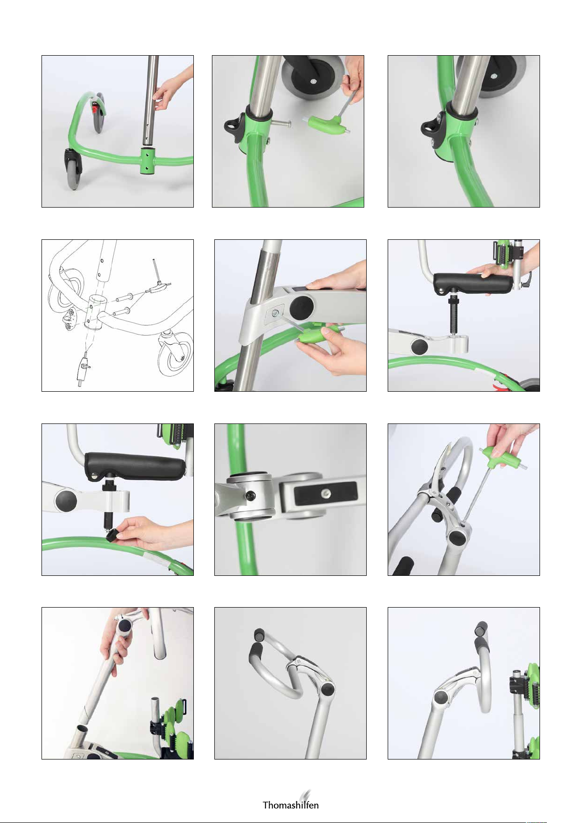
1. Das dicke Zentralrohr so in die Aufnahme des Untergestells stecken, dass die Löcher im Rohr mit den Löchern der
Aufnahme fluchten (Abb. 1). Die beiliegenden Inbusschrauben von der Gestellinnenseite durch die Löcher der Gestellaufnahme und des Zentralrohrs führen (Abb. 2).
2. Das Kunststoffauge mit den vormontierten Muttern zur Hand nehmen und dieses an der Vorderseite des tGo gegen
die Löcher im Gestell halten, in denen die Inbusschrauben stecken. Die Schrauben in die Muttern des Kunststoffauges drehen. Stellen Sie sicher, dass Zentralrohr und Untergestell fest miteinander verbunden sind (Abb. 3).
3. Im unteren Ende des Zentralrohres befindet sich eine schwarze Kunststoffbuchse. Ziehen Sie die beiden Inbusschrauben von unten an. Achten Sie darauf, min. 15 Umdrehungen jeder Schraube vorzunehmen. (Abb. 4)
4. Nun die Inbusschraube lösen, die seitlich im vorderen Element des zentralen Gelenkarms verschraubt ist. Den Gelenkarm derart auf das Zentralrohr stecken, dass der Arm in die Gestellinnenseite des tGo zeigt und der aufgewölbte
Teil des vorderen Metallelements nach oben zeigt. Den Gelenkarm rechtwinklig zur Vorderseite des Untergestells
ausrichten und mit der Inbusschraube fixieren, die seitlich am vorderen Element sitzt (Abb. 5). Stellen Sie sicher, dass
Zentralrohr und Gelenkarm fest miteinander verbunden sind und der Gelenkarm bei Belastung nicht nach unten
rutscht.
5. Die untere Mutter lösen, die sich an der Gewindestange unterhalb des Sattels befindet. Die Gewindestange in das
vordere der beiden Aufnahmelöcher im hintersten Element des Gelenkarms stecken (Abb. 6). Vor dem Sattel befindet sich ein Rohr, das nach oben zeigt. Achten Sie darauf, dass der Sattel mit dem Rohr in Fahrtrichtung in die Aufnahme gesteckt wird. Die entfernte Mutter unterhalb des Gelenkarms wieder auf die Gewindestange drehen. Achten
Sie darauf, dass der Gummiring in der Mutter hierbei nach oben zeigt (Abb. 7). Die Mutter festziehen.
6. Den Lenker zur Hand nehmen. Die Inbusschraube im Gelenk am oberen Ende des Lenkerrohres lösen. Hierzu muss
der Klemmhebel gelöst werden und der Lenker in eine derartige Position gebracht werden, dass das Loch in der
Lenkeraufnahme mit der Längsbohrung im Lenkerrohr fluchtet (Abb. 8). Jetzt kann die lange Seite des Inbusschlüssels
in das Rohr geführt werden, bis sie in die Inbusschraube greift (Abb. 9). Die Schraube lösen.
7. Das Lenkerrohr in das Zentralrohr des tGo stecken (Abb. 10). Sie können den Lenker um 360° im Zentralrohr
drehen. So können Sie wählen, ob der Arm der Lenkeraufnahme nach vorne (Abb. 11) oder nach hinten (Abb. 12)
zeigen soll. Den Lenker anschließend parallel zur Vorderseite des tGo ausrichten. Fixieren Sie die Lenkstange, indem
Sie die Inbusschraube im Lenkerrohr fest anziehen. Den Lenker in die gewünschte Position bringen und mit dem
Klemmhebel fixieren (Abb. 13). Den Klemmhebel mit dem eingebauten Schieber arretieren.
8. Die Beckenpelotten auf das Rohr vor dem Sattel stecken. Hierzu muss die Schraube an der Rohraufnahme gelöst
werden. Die Inbusschrauben, die die einzelnen Pelotten verbinden, sollten mit ihrem Kopf nach oben zeigen. Die
Schraube an der Rohraufnahme fest anziehen, um die Pelotten zu fixieren (Abb. 14).
9. Zur Montage der Brustpelotten die Schraube im Rohr der Brustpelotten lösen. Das Rohr in das Rohr vor dem Sattel
des tGos stecken, sodass die Brustpelotten oberhalb der Beckenpelotten sitzen (Abb. 15). Das Rohr durch Anziehen
der Schraube im Inneren fixieren.
10. Zur Montage der Rumpfpelotten, den Klemmhebel an der Rückseite der Rumpfstütze lösen. Das Rohr der Rumpfstütze von hinten in das Rohr schieben, auf dem der Sattel sitzt. Die Rumpfstütze mit dem Klemmhebel fixieren
(Abb. 16).
9

Bedienungsanleitung – tGo
Anpassen des Walkers an das Kind / Verstellmöglichkeiten
Die Einstellungen / Anpassungen sind grundsätzlich durch geschulte bzw. eingewiesene Fachleute (z.B. Medizinprodukteberater des Sanitäts-Fachhandels) vorzunehmen.
Einstellen der Sattelhöhe
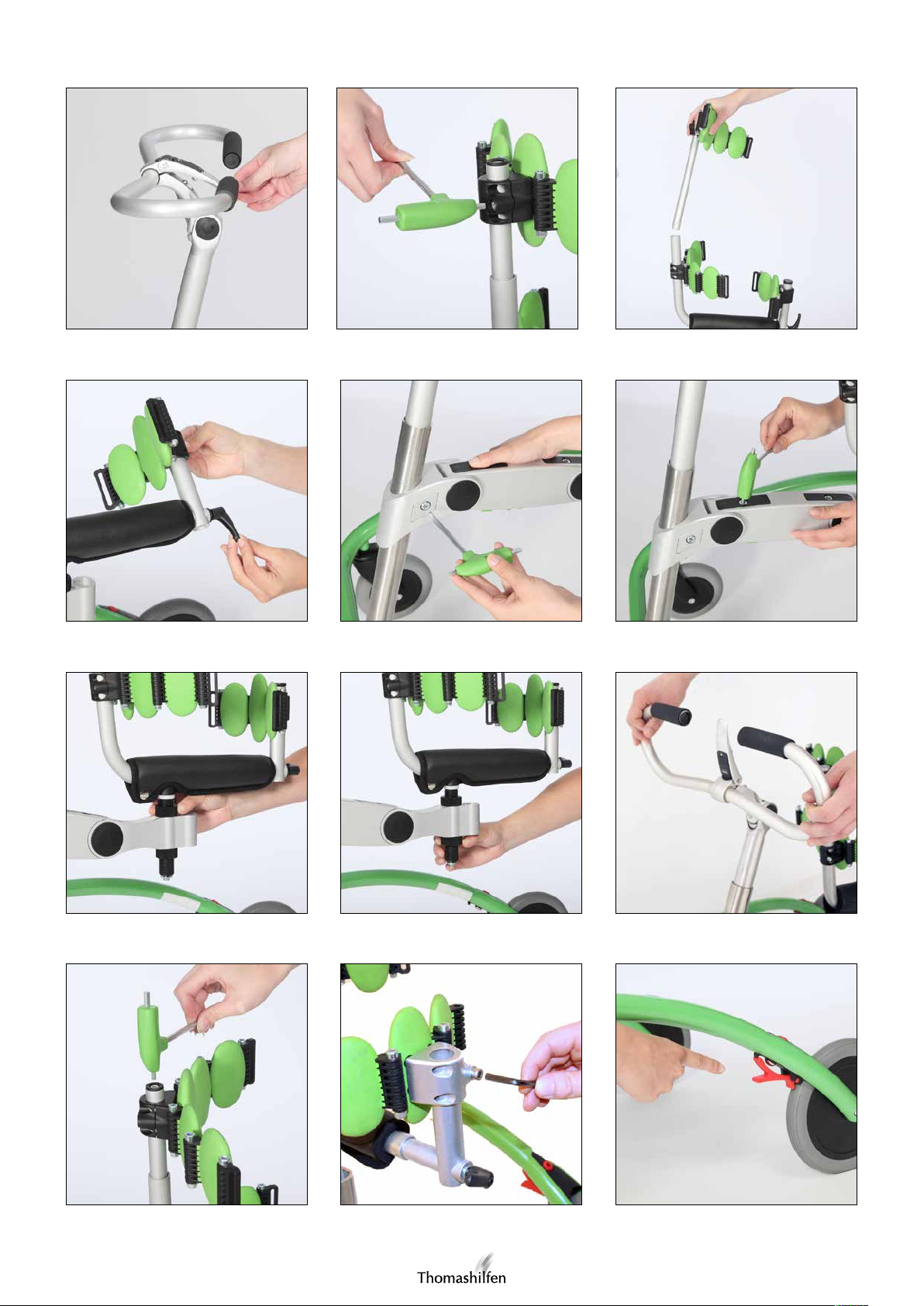
1. Zunächst die Höhe des Gelenkarms am Zentralrohr einstellen. Hierzu die Schraube seitlich am vordersten Element
des Gelenkarms lösen und den Gelenkarm in der Höhe verschieben (Abb. 17). Nach der Verstellung den Gelenkarm
mit der Schraube am vordersten Element fixieren. Stellen Sie sicher, dass Zentralrohr und Gelenkarm fest miteinander
verbunden sind und der Gelenkarm bei Belastung nicht nach unten rutscht.
2. Die Feineinstellung der Sattelhöhe und des Sattelwinkels erfolgt über die Gelenke des Gelenkarms und die Gewindestange unterhalb des Sattels. Zur Verstellung des Gelenkwinkels jeweils die Schraube lösen, die sich in der schwarzen Fläche auf der Gelenkoberseite befindet (Abb. 18). Den Gelenkarm in die gewünschte Position bringen und
durch Anziehen der Schraube auf der Gelenkoberseite fixieren.
3. Zur Verstellung der Sattelhöhe über die Gewindestange unterhalb des Sattels, die Mutter auf der Gewindestange
oberhalb des Gelenkarms nach oben (Sattelhöhe wird geringer) oder nach unten (Sattelhöhe wird größer) drehen
(Abb. 19). Wenn Sie die gewünschte Höhe eingestellt haben, fixieren Sie die Sattelhöhe, indem Sie die Mutter unterhalb des Gelenkarms so weit wie möglich nach oben drehen und fest ziehen (Abb. 20).
Veränderung der Sattelposition
Der Sattel kann in zwei verschiedenen Positionen montiert werden, um die Entfernung zum Lenker zu verändern. Gehen Sie dabei wie folgt vor:
1. Die untere Mutter lösen, die sich an der Gewindestange unterhalb des Sattels befindet. Die Gewindestange in das
vordere oder hintere der beiden Aufnahmelöcher im hintersten Element des Gelenkarms stecken (Abb. 6). Vor dem
Sattel befindet sich ein Rohr, das nach oben zeigt. Achten Sie darauf, dass der Sattel mit dem Rohr in Fahrtrichtung
in die Aufnahme gesteckt wird.
2. Die entfernte Mutter unterhalb des Gelenkarms wieder auf die Gewindestange drehen. Achten Sie darauf, dass der
Gummiring in der Mutter hierbei nach oben zeigt (Abb. 7). Die Mutter fest anziehen.
Lenker einstellen
1. Verstellen Sie zunächst die Höhe des Lenkers, indem Sie die Inbusschraube im Gelenk am oberen Ende des Lenkerrohres lösen. Hierzu muss der Klemmhebel gelöst werden und der Lenker in eine derartige Position gebracht
werden, dass das Loch in der Lenkeraufnahme mit der Längsbohrung im Lenkerrohr fluchtet (Abb. 8). Jetzt kann die
lange Seite des Inbusschlüssels in das Rohr geführt werden, bis sie in die Inbusschraube greift (Abb. 9).
2. Das Lenkerrohr nun im Zentralrohr des tGos verschieben, bis die gewünschte Position erreicht ist. Bitte beachten
Sie hierbei die Markierung, bis zu der das Lenkerrohr maximal ausgezogen werden darf. Sie können den Lenker um
360° im Zentralrohr drehen. So können Sie wählen, ob der Arm der Lenkeraufnahme nach vorne (Abb. 11) oder
nach hinten (Abb. 12) zeigen soll. Den Lenker anschließend parallel zur Vorderseite des tGos ausrichten. Fixieren Sie
die Lenkstange, indem Sie die Inbusschraube im Lenkerrohr fest anziehen.
3. Bringen Sie den Lenker in die gewünschte Position (Abb. 21) und fixieren Sie ihn mit dem Klemmhebel (Abb. 13).
Den Klemmhebel mit dem eingebauten Schieber arretieren.
Anpassen der Pelottenhöhe
1. Die Beckenpelotten können in der Höhe verstellt werden. Hierzu muss die Schraube an der Rohraufnahme gelöst
werden. Die Beckenpelotten können nun in der Höhe auf dem Rohr verschoben werden. Die Schraube an der Rohraufnahme wieder fest anziehen, um die Pelotten zu fixieren (Abb. 14).
2. Die Brustpelotten können über das Rohr, auf dem sie befestigt sind, in der Höhe verstellt werden. Hierzu die Schraube im oberen Ende des Brustpelottenrohres lösen (Abb. 22) und das Rohr in der Höhe verschieben. Zum Fixieren
der Brustpelotten, die Schraube wieder fest anziehen.
3. Die Rumpfpelotten können in der Höhe verstellt werden. Hierzu muss die Schraube an der Rohraufnahme gelöst
werden (Abb. 23). Die Rumpfpelotten können nun in der Höhe auf dem Rohr verschoben werden. Ziehen Sie die
Schraube an der Rohraufnahme wieder fest an, um die Pelotten zu fixieren.
10

Bedienungsanleitung – tGo
Funktion der Rumpfpelotte
Um dem Kind den Einstieg in den tGo zu erleichtern, kann die Rumpfpelotte schnell über den Klemmhebel gelöst und
nach hinten herausgezogen werden. Ebenso kann über den Klemmhebel die Rumpfpelotte in der Tiefe verstellt werden.
Achten Sie darauf, dass der Klemmhebel nach jeder Verstellung fest angezogen wird.
Einstellen des Gurtes
Der Gurt kann über die Schiebeschnalle in der Länge verstellt werden (Abb. 28). Der Klettverschluss am Gurtende dient
dazu, den Gurt öffenen und schließen zu können (Abb. 27).
ACHTUNG: Der Klettverschluss muss immer vollständig geschlossen sein, wenn sich das Kind im tGo befindet.
Anpassen der Pelottenanzahl
Die Pelottenanzahl können flexibel an die Bedürfnisse des Kindes anpassen. Siehe hierzu den Punkt „zusätzliche Pelottenelemente“ im Bereich der Zubehörmontage dieser Anleitung.
Feststellen / Lösen der Schwenkfunktion des Sattels
Um zwischen der Schwenkfunktion des Sattels und der starren Sattelposition zu wechseln, muss das Kind aus dem tGo
genommen werden. Anschließend den Sattel des tGos demontieren. Entfernen Sie die Inbusschraube und Unterlegscheibe am unteren Ende der Gewindestange des Sattels. Nun kann die Gewindestange nach unten abgezogen werden.
Die Gewindestange ist an ihren beiden Enden mit unterschiedlich geformten Aussparungen versehen. Wenn die Gewindestange mit dem rechteckigen Ausschnitt nach oben auf die Aufnahme gesteckt wird, ist der Sattel in seiner Position
fixiert. Die Schwenkfunktion ist deaktiviert.
Wenn die Gewindestange mit der anderen Seite nach oben auf die Aufnahme gesteckt wird, ist die Schwenkfunktion
aktiviert. Montieren Sie den Sattel nach der Einstellung wieder am tGo (zur Montage siehe Aufstellen und Montage,
Abschnitt 4).
Feststellbremse
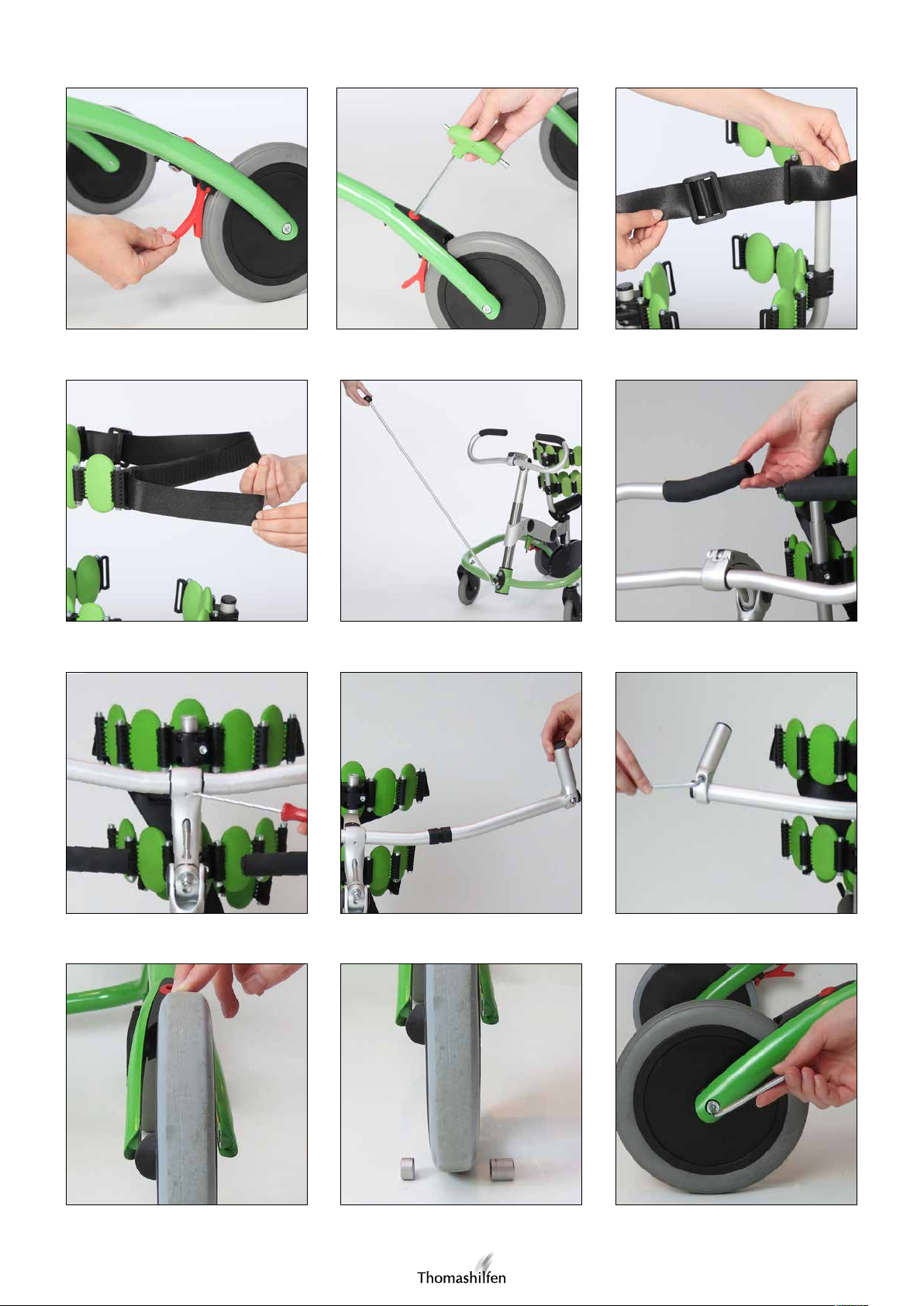
Um die Feststellbremse zu arretieren, klappen Sie die roten Hebel (Abb. 24), die sich an der Gestellunterseite vor den
Rädern befinden, herunter, sodass sie die Räder blockieren (Abb. 25). Zum Lösen der Feststellbremse werden die Hebel
hochgeklappt.
Schleifbremse
Die Schleifbremse wird über den roten Verstellmechanismus an der Gestelloberseite vor den Hinterrädern angezogen.
An dem roten Verstellpunkt findet sich eine Markierung. Wenn diese in Fahrtrichtung zeigt, ist die Schleifbremse gelöst.
Sie kann Schrittweise über fünf Stufen mittels Inbusschlüssel angezogen werden. Hierzu drehen Sie den roten Verstellpunkt entgegen des Uhrzeigersinns (Abb. 26). Wenn die fünfte Position überschritten wird, zeigt die Markierung erneut
in Fahrtrichtung; die Schleifbremse ist deaktiviert.
Montage des Zubehörs
Anbau und Einstellung vertikale Handgriffe
Montage
Zur Montage der vertikalen Handgriffe (erhältlich als Zubehör) muss der Lenker der Grundausstattung getauscht werden. Entfernen Sie auf einer Seite des Lenkers die Schaumstoffummantelung, indem Sie diese vom Lenker der Grundausstattung abziehen. (Abb. 30) Lösen Sie die kleine Schraube aus Plastik an der Lenkeraufnahme mit Hilfe eines
Schraubenziehers (Abb. 31) und legen Sie die Schraube beiseite. Entfernen Sie das Lenkrohr indem Sie die Seite ohne
Schaumstoffummantelung durch den Ring der Lenkaufnahme führen. Lockern Sie die Sechskantschraube an einem der
Hörnchen. Entfernen Sie das Hörnchen und schieben Sie den Lenker so durch den Ring der Lenkeraufnahme, dass die
Schraube der Griffaufnahme vom tGo weg zeigt (Abb. 32). Ziehen Sie die Schraube an der Lenkeraufnahme wieder fest.
Stecken Sie das Hörnchen auf den Lenker, sodass die Befestigungsschraube vom tGo weg zeigt und ziehen Sie diese fest
(Abb. 33). Stellen Sie vor Benutzung sicher, dass die Schrauben fest angezogen sind.
11

Bedienungsanleitung – tGo
Beintrennplatte
Die Beintrennplatte wird im hintersten Element des Gelenkarms, wo auch der Sattel angebracht ist, befestigt. Montieren
Sie die Beintrennplatte wahlweise im vorderen oder hinteren der beiden Aufnahmelöcher im hintersten Element des Gelenkarms. Zur Montage der Beintrennplatte muss der Sattel entfernt werden. Die Beintrennplatte von unten in eines der
Aufnahmelöcher des Gelenkarms stecken. Die Beintrennplatte mit der Mutter sichern. Montieren Sie den Sattel wieder
am tGo (zur Montage siehe Aufstellen und Montage, Abschnitt 4).
Zusätzliche Pelottenelemente
Die Anzahl der Pelotten des tGo kann individuell gestaltet werden. Zum Anbau weiterer Pelotten muss zunächst das
schwarze Kunststoffelement, das mit einem Schlitz für den Gurt versehen ist, entfernt werden. Hierzu die Schraube
entfernen, die die äußere Pelotte mit dem Kunststoffelement verbindet (benötigt werden der mitgelieferte Inbusschlüssel
und ein 10er Ring- oder Maulschlüssel).
Ziehen das schwarze Kunststoffelement aus der Pelotte. Stecken Sie beliebig viele Pelotten an den Pelottenring an. Achten Sie darauf, dass die schwarzen Kunststoffhalter der Pelotten jeweils von Körper des Kindes weg gerichtet sind. Die
Pelotten jeweils mit den mitgelieferten Schrauben und Muttern befestigen. Abschließend die Elemente zur Gurtführung
wieder an den Pelottenring setzen und befestigen.
Zum Ausbau nicht benötigter Pelotten gehen Sie bitte analog vor.
Anbau und Einstellung Sitz-Brems-System
Montage
Zur Montage des Sitz-Brems-Systems müssen die Hinterräder der Grundausstattung gegen die Hinterräder mit integriertem Sitz-Brems-System (erhältlich als Zubehör) getauscht werden. Dies sollte nur vom Fachhandel durchgeführt werden.
Hierzu muss jeweils die Sechskantschraube entfernt werden, durch die der Rahmen des tGos mit dem Rad verschraubt
ist (Abb. 36). Nun können die Standard-Räder gegen die Räder mit integriertem Sitz-Brems-System getauscht werden.
Achten Sie darauf, dass die Federung senkrecht zum Boden steht bei der Montage (Abb. 38). Befestigen Sie die Räder
mit den Sechskantschrauben am Gestell des tGos.
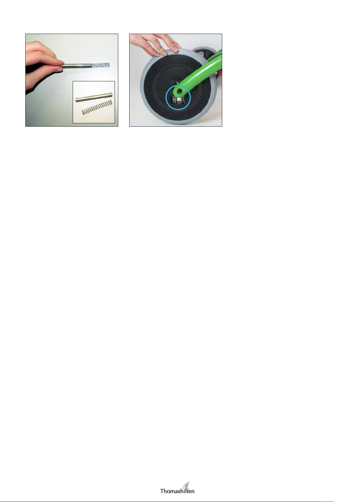
Wenn Sie ein sehr leichtes Kind versorgen, kann es erforderlich sein, eine Feder aus dem Sitz-Brems-System zu entfernen.
Entnehmen Sie dazu die beiden Inbusschrauben des Rades. Legen Sie die Kappe beiseite, entnehmen Sie einen der
Metallstifte und ziehen Sie die Feder ab (Abb. 37). Legen Sie den Stift wieder ohne die Feder in die Vorrichtung. Achten
Sie darauf, dass die Feder des anderen Stiftes in die Aussparung gespannt ist. Schrauben Sie die Kappe wieder, mit der
Rundung nach unten zeigend, fest. Stellen Sie vor Benutzung sicher, dass die Schrauben fest angezogen sind.
Anbau und Einstellung Rücklaufsperre
Montage
Zur Montage der Rücklaufsperre müssen die Hinterräder der Grundausstattung gegen die Hinterräder mit integrierter
Rücklaufsperre (erhältlich als Zubehör) getauscht werden. Dies sollte nur vom Fachhandel durchgeführt werden. Hierzu
muss jeweils die Sechskantschraube entfernt werden, durch die der Rahmen des tGos mit dem Rad verschraubt ist.
(Abb. 36) Nun können die Standard-Räder gegen die Räder mit integrierter Rücklaufsperre getauscht werden. Montieren
Sie die Räder so, dass die Wölbung aus Kunststoff (Abb. 34) jeweils nach links zeigt. Legen Sie in diese Seite die kleinere Metalldistanzhülse ein. Montieren Sie das Rad auf der anderen Seite mit der größeren Metalldistanzhülse (Abb. 35).
Befestigen Sie die Räder mit den Sechskantschrauben am Gestell des tGos. Stellen Sie vor Benutzung sicher, dass die
Schrauben fest angezogen sind.
Zugstange
Die Zugstange kann bei Bedarf in das Kunststoffauge am Untergestell eingehakt werden (Abb. 29).
12

Bedienungsanleitung – tGo
Produkt- / Serien-Nummer (Rückschluss auf das Baujahr)
Zum Erhalt der richtigen Ersatzteile bzw. für mögliche
technische Rückrufe benötigen wir grundsätzlich die
Angabe der Serien- / Chargen-Nummer und die genaue
Artikel-Nummer. Anhand der Serien- / Chargen-Nummer
können Sie bei uns das Herstellungsjahr Ihres tGos erfragen.
Die Serien- / Chargen-Nummer und auch die Artikel-Nummer des tGos befinden sich auf dem Strichcode-Label, das
am Untergestell angeb+racht ist.
Artikel-Nummer
Serien- / ChargenNummer
Reinigungs-, Desinfektions- und Pflegehinweise
Sie können alle Teile des tGos mit einem weichen, wenn notwendig feuchten Tuch abwischen. Für hartnäckige Verschmutzungen können haushaltsübliche Reinigungs- und Desinfektionsmittel verwendet werden.
Garantiebedingungen / CE - Kennzeichnung
Thomashilfen bietet Ihnen ab Kaufdatum eine 2-jährige Garantie auf alle Rahmenteile. Die Garantie umfasst alle Ansprüche, die die Funktion beeinträchtigen. Ausgenommen sind Schäden, die durch unsachgemäße Handhabung (z. B.
Überbelastung), sowie natürlichen Verschleiß entstehen. Der tGo entspricht den Anforderungen der internationalen
Norm DIN EN ISO 11199-3 TZ 4.3 und ist mit einer CE-Kennzeichnung versehen. Wir wünschen Ihnen viel Freude mit
Ihrem tGo Gehtrainer!
Wartung / Wiedereinsatz
Service und Reparaturen am Gehtrainer dürfen nur vom Fachhandel durchgeführt werden. Der Benutzer dieses
Reha-Hilfsmittels hat darauf zu achten, dass die vorgeschriebenen Inspektionen / Wartungen regelmäßig und rechtzeitig erfolgen. Ist ein Schaden erkennbar, muss der Nutzer aktiv informieren und den Schaden sofort durch Fachpersonal
beheben lassen. Für Reparaturen dürfen ausschließlich Original-Ersatzteile verwendet werden (die Liste der Austausch- /
Ersatzteile finden Sie im Download-Bereich auf unserer Internet-Seite www.thomashilfen.de).
Demontagen / Montagen von Ersatzteilen dürfen grundsätzlich nur durch Fachpersonal durchgeführt werden! Bei erforderlichen Rücksendungen an Ihren Fachhandel achten Sie bitte darauf, das Fahrgestell transportsicher zu verpacken.
Machen Sie sich mit den Funktionen des Produktes vertraut. Sollten Sie das Produkt nicht kennen, studieren Sie vor der
Prüfung die Bedienungsanleitung. Reinigen Sie das Produkt vor Prüfbeginn. Beachten Sie hierzu Reinigungs-, Desinfektions- und Pflegehinweise.
Überprüfen Sie den tGo anschließend auf Schäden / Risse am Gestell inkl. Lenker, den Rädern inkl. Radgabeln, Sattel,
an den Bremsen und sämtlichen Pelottenelementen.
Der tGo ist zum Wiedereinsatz geeignet. Dieses Reha-Produkt unterliegt aber einer außergewöhnlichen Beanspruchung.
Aufgrund von Marktbeobachtungen und dem Stand der Technik haben wir die Produktlebensdauer bei sachgemäßem
Gebrauch und unter Einbeziehung der Service- und Wartungsarbeiten auf 5 Jahre kalkuliert. Zeiten der Einlagerung
beim Fachhandel sind ausgenommen.
Bei entsprechender Pflege und Wartung ist das Produkt auch deutlich über diesen Zeitraum hinaus zuverlässig.
Für den Wiedereinsatz ist das Produkt grundsätzlich immer sorgfältig zu reinigen und zu desinfizieren. Der Zustand ist
von geschultem Fachpersonal auf Verschleiß und Beschädigungen hin zu prüfen. Beanstandungen müssen behoben
werden, um einen weiteren sicheren Gebrauch des tGo zu gewährleisten. Beachten Sie hierzu die Wartungshinweise.
Dem Produkt muss für den Wiedereinsatz eine Bedienungsanleitung beiliegen. Sollte keine verfügbar sein, fordern Sie
diese bei Thomashilfen an oder laden Sie sich diese im Download-Bereich unserer Internet-Seite www.thomashilfen.de
herunter.
Ist der tGo aufgrund seines Zustandes nicht mehr verwendungsfähig, kann er beim örtlich zuständigen Entsorgungsunternehmen recycelt werden.
13

User manual – tGo
Dear tGo user,
Thank you very much for the trust you have placed in us and for purchasing this product. With your tGo you have acquired an innovative product from the Thomashilfen range.
To ensure the tGo is safe, practical and comfortable for both you and in particular for your child, please read these
operating instructions first.
Should you still have questions or problems, please refer to your specialist dealership or contact us directly. In this context we would like to draw your attention to our website at www.thomashilfen.com where you will also be able to access
up-to-date information.
Our mailing address: Thomas Hilfen für Körperbehinderte GmbH & Co. Medico KG
Walkmühlenstraße 1
D - 27432 Bremervörde
Germany
Phone: +49 (0)4761 886-63 or -68
www.thomashilfen.com
Contents Page
Permissible operating conditions/places of use ................................................................................................. 14
Risks of use and contraindications .................................................................................................................... 14
Intended purpose / indication........................................................................................................................... 15
Safety checks and maintenance intervals .......................................................................................................... 15
Notes on safety ................................................................................................................................................ 15
Symbols and warning signs .............................................................................................................................. 16
Technical specifications ................................................................................................................................... 16
Basic configuration .......................................................................................................................................... 17
Accessories ...................................................................................................................................................... 17
Setup and assembly ......................................................................................................................................... 17
Adjusting the gait trainer to the child/range of adjustments ............................................................................... 18
Parking brake .................................................................................................................................................. 19
Friction brake ................................................................................................................................................... 19
Fitting the accessories ..................................................................................................................................... 19
Product/serial number ..................................................................................................................................... 21
Notes on cleaning, disinfection and care .......................................................................................................... 21
Warranty conditions/CE marking ...................................................................................................................... 21
Maintenance/reuse .......................................................................................................................................... 21
Permissible operating conditions/places of use
Before the tGo is used for the first time, it must be instructed by a trained specialist.
CAUTION: The tGo is exclusively meant for secure indoor gait training. Its design is particularly suited for use in living
areas.
Risks of use and contraindications
Using this product properly will prevent any risks from arising during use. There are no contraindications associated
with proper use.
14

User manual– tGo
Intended purpose/indication
Walking/gait training for the following conditions:
• Children with impaired motor development
• Following impairment of the CNS (impairment of the CNS function or following infection/tumors)
• Post traumatic/post infection conditions with disorders of the musculoskeletal system, where applicable with
dosed relief
• Children with cerebral impairment of the locomotor system (diparesis, tetraparesis)
• Children with spina bifida
• Neurological diseases
• Craniocerebral injuries
• Muscle diseases (congenital/acquired/progressive)
• Metabolic nerve, muscle and bone diseases
Safety checks and maintenance intervals
A regular check of the operating controls and securing screws should be carried out by a trained specialist every month.
Please remember to re-secure the screws and locking levers following each adjustment.
Notes on safety
• Before using the tGo for the first time, read the operating instructions carefully – or have them read aloud to you if
you have difficulty reading. If you have lost the operating instructions you can download them at any time from the
download page of our website at www.thomashilfen.com
• We recommend that you read just the settings of the tGo at least every three months to suit the actual size of your
child’s body. This should be carried out with assistance from your therapist/orthopedic technician where appropriate.
• Never leave the tGo user unsupervised in the gait trainer!
• The proper function of the parking brake should be checked before each use of the tGo. If the brake does not function properly the tGo may not be used. Please contact your specialist dealer to resolve the problem.
• CAUTION: It should be ensured that limbs are not trapped in the gap between the wheel and the wheel fork.
• CAUTION: Be aware that there is an increased pinch hazard when making settings and adjustments to the tGo.
• CAUTION: Wet wheels can affect the performance of the brakes. During a longer pause you should secure the tGo
against unintended rolling by applying the parking brake.
• The gait trainer should only be used on a level, horizontal and firm surface. Be aware of unevenness and holes in the
floor. There is a risk of tipping over or becoming stuck.
• You should not hang or place heavy bags or other similar items on the tGo because this will increase the risk of it
tipping over.
• Please keep your children away from the packaging – there is a risk of suffocation.
• When accessory parts are removed tube ends may be left open. These may be sharp-edged and therefore present a
risk of injuries to fingers that are poked into these openings. The tGo and its accessories have been designed to avoid
such risks. However, should open-ended tubes still present a risk they should be closed off using plastic plugs.
• The pad elements must not be eaten.
15

User manual – tGo
Symbols and warning signs
Sticker Meaning
Specification labels / loading capacity stickers
The specification label is attached to the rear of the
central tube.
The specification label includes the name of the manufacturer, including the address; the type designation, the
maximum loading capacity and the CE label.
Bar code label
The barcode label is attached to the front of the base.
The bar code label includes the item number, designati-
on, serial number and production date of the product.
Note on use
The instruction for use is attached to the front of the
central tube.
The sticker refers to the use of the product only indoors
and to the reading of the instructions for use.
Technical specifications and versions
tGo 1 tGo 2
Seat height 250 mm - 600 mm / 9.8 - 23.6" 250 - 800 mm / 9.8 - 31.5"
Overall dimensions 830 x 540 mm / 32.7 x 21.3" 920 x 650 mm / 36.2 x 25.6"
Handgrip height 430 - 900 mm / 16.9 - 35.4" 450 - 1100 mm / 17.7 - 43.3"
Pelvis support height 400 - 750 mm / 15.8 - 29.5" 400 - 950 mm / 15.8 - 37.4"
Wheel size - front 150 mm / 5.9" 150 mm / 5.9"
Wheel size - rear 200 mm / 7.9" 200 mm / 7.9"
Weight 12.4 kg / 27.3 lbs 13.8 kg / 30.4 lbs
Max. user weight 40 kg / 88.2 lbs 45 kg / 99.2 lbs
tGo is available in the following versions:
Item code Description
1887 tGo gait trainer size 1
1888 tGo gait trainer size 2
Material
Aluminum, stainless steel, steel (painted), plastic, rubber, polyester, polyurethane
16

User manual – tGo
Basic configuration
In the basic configuration the tGo is supplied with the following parts:
Subframe with parking brake and friction brake, Height and angle adjustable handgrips, Swiveling saddle, Pads for chest
(5 elements), pelvis (5 elements) and trunk (3 elements), Strap for the chest pads, Allen wrench with 2 different end
sizes, Castoring front wheels with steering lock
Accessories
The following accessories are available for the tGo:
Seat brake system, Leg separator plate, Additional pads, Split handgrips, Vertical handgrips, Return stop, Pull rod
Setup and assembly
At delivery, the tGo is knocked down into its individual parts. Follow these individual steps to assemble your tGo:
1. Place the wide central tube into the locator on the subframe such that the holes in the tube are aligned with the
holes in the locator (fig. 1). Fit the Allen bolts provided through the holes in the frame locator and central tube from
the inside (fig. 2).
2. Take the plastic eye with pre-fitted nuts and offer this up to the holes in the front side of the tGo through which the
Allen bolts are protruding. Tighten the screws into the nuts in the plastic eye. Ensure that the central tube and subframe are securely fastened together (fig. 3).
3. Tighten the two Allen bolts in the black plastic part inside the lower end of the central tube. Ensure that each bolt is
turned fifteen times at least (fig. 4).
4. Now loosen the Allen bolt that is screwed into the front element of the central articulating arm from the side. Press
the articulating arm onto the central tube such that the arm is pointing towards the inside of the tGo frame and the
bulged part of the front metal element is facing upwards. Align the articulating arm at right angles to the front side of
the subframe and fasten with the Allen bolt that is located on the front element (fig. 5). Ensure that the central tube
and articulating arm are securely fastened together and that the articulating arm cannot slip downwards under load.
5. Loosen the lower nut that is located on the threaded rod beneath the saddle. Insert the threaded rod into the foremost of the two locating holes in the rearmost element of the articulating arm (fig. 6). In front of the saddle is a tube
that points upwards. Ensure that the saddle – together with the tube – is inserted into the locator in the direction
of travel. Replace the removed nut onto the threaded rod beneath the articulating arm. In so doing, ensure that the
rubber O-ring within the nut is facing upwards (fig. 7). Tighten the nut.
6. Take the handlebars in your hands. Undo the Allen bolt in the joint at the upper end of the handlebar tube. To do
this, the locking lever must first be released and the handlebar positioned such that the hole in the handlebar locator
aligns with the oblong hole in the handlebar tube (fig. 8). Now the long end of the Allen wrench can be inserted into
the tube until it locates into the head of the Allen bolt (fig. 9). Undo the bolt.
7. Insert the handlebar tube into the central tube of the tGo (fig. 10). You can turn the handlebar through 360° within
the central tube. This allows you to choose whether the handlebar locating bracket should face forwards (fig. 11) or
backwards (fig. 12). Then align the handlebar so that it is parallel with the front side of the tGo. Secure the handlebar by fully tightening the Allen bolt inside the handlebar tube. Place the handlebar in the desired position and lock
in-place with the locking lever (fig. 13). Secure the locking lever with the built-in slider.
8. Slot the pelvis pad onto the tube in front of the saddle. To do this, the screw on the tube locator must first be loosened. The Allen bolts that connect the various pads should be fitted such that their heads are pointing upwards.
Tighten the screw on the tube locator in order to secure the pads in position (fig. 14).
9. To fit the chest pads, first loosen the screw in the chest pad tube. Slot the tube into the tGo saddle tube such that the
chest pads are positioned above the pelvis pads (fig. 15). Secure the tube in-place by tightening the internal screw.
10. To fit the torso pads, first loosen the locking lever on the back of the torso rest. From behind, push the torso rest tube
into the tube on which the saddle is mounted. Secure the torso rest with the locking lever (fig. 16).
17

User manual – tGo
Adjusting the gait trainer to the child/range of adjustments
Settings/adjustments may only be undertaken by specialists that have received the requisite training or instruction (e.g. a
medical product consultant at a medical appliance specialist dealership).
Setting the saddle height
1. First set the height of the articulating arm at the central tube. To do this, undo the screw that is located on the side
of the front element and slide the articulating arm to adjust its height (fig. 17). Once the articulating arm has been
adjusted, secure it with the screw located on the front element. Ensure that the central tube and articulating arm are
securely fastened together and that the articulating arm cannot slip downwards under load.
2. Fine adjustment of the saddle height is achieved via the joints on the articulating arm and the threaded rod beneath
the saddle. To adjust the joint angle undo the respective screw that is located in the black area on the upper surface
of the joint (fig. 18). Place the articulating arm in the desired position and secure in-place by tightening the screw on
the upper surface of the joint.
3. To adjust the saddle height via the threaded rod beneath the saddle, rotate the nuts on the threaded rod above the
articulating arm upwards (saddle height is reduced) or downwards (saddle height is increased) (fig. 19). Once you
have set the desired height, secure the saddle at that height by rotating the nut below the articulating arm upwards as
far as possible and tightening it (fig. 20).
Changing the saddle position
The saddle can be fitted in two different positions. This allows its distance to the handlebar to be changed. To do this,
proceed as follows:
1. Loosen the lower nut that is located on the threaded rod beneath the saddle. Insert the threaded rod into the front or
rear of the two locating holes in the rearmost element of the articulating arm (fig. 6). Ensure that the saddle – together with the tube – is inserted into the locator in the direction of travel.
2. Replace the removed nut onto the threaded rod beneath the articulating arm. In so doing, ensure that the rubber
O-ring within the nut is facing upwards (fig. 7). Tighten the nut.
Adjusting the handlebar
1. First adjust the height of the handlebar by undoing the Allen bolt in the joint at the upper end of the handlebar tube.
To do this, the locking lever must first be released and the handlebar positioned such that the hole in the handlebar
locator aligns with the oblong hole in the handlebar tube (fig. 8). Now the long end of the Allen wrench can be
inserted into the tube until it locates into the head of the Allen bolt (fig. 9).
2. Insert the handlebar tube into the central tube of the tGo until it has reached the desired position. Please note that
the handlebar tube may only be pulled out as far as the mark – and no further. You can turn the handlebar through
360° within the central tube. This allows you to choose whether the handlebar locating bracket should face forwards
(fig. 11) or backwards (fig. 12). Then align the handlebar so that it is parallel with the front side of the tGo. Secure the
handlebar by fully tightening the Allen bolt inside the handlebar tube.
3. Place the handlebar in the desired position (fig. 21) and lock in-place with the locking lever (fig. 13). Secure the
locking lever with the built-in slider.
Adjusting the pad height
1. The height of the pelvis pad can be adjusted. To do this, the screw on the tube locator must be loosened. The pelvis
pad can now be slid up and down the tube to the desired height. Re-tighten the screw on the tube locator to secure
the pelvis pad (fig. 14).
2. The height of the chest pad can be adjusted by moving the tube to which it is fastened. To do this, undo the screw
at the top of the chest pad tube (fig. 22) and slide the tube to the desired height. Re-tighten the screw to secure the
chest pad.
3. The height of the torso pad can be adjusted. To do this, the screw on the tube locator must be loosened (fig. 23).
The torso pads can now be slid up and down the tube to the desired height. Re-tighten the screw on the tube locator
to secure the pads.
18

User manual – tGo
Function of the torso pad
To make it easier for the child to enter the tGo the torso pad can be rapidly released via the locking lever and pulled
out from behind. The locking lever can also be used to adjust the depth of the torso pad. Always ensure that the locking
lever is returned to the locked position after making adjustments.
Adjusting the belt
The belt can be adjusted in length using the sliding buckle. (fig. 28) The Velcro fastener at the end of the belt serves to
open and close the belt. (fig. 27).
Caution: The Velcro fastener must always be fully closed when the child is in the tGo.
Changing the number of pads
The number of pads can be adjusted flexibly to the child. For instructions see „additional pad elements“ in the section
„Fitting accessories“.
Locking/releasing the swiveling function of the saddle
The child must first always be removed from the tGo when changing between the swinging function of the saddle and
its fixed position. Then remove the saddle of the tGo. Remove the Allen bolt and washer located at the lower end of
the saddle’s threaded rod. Now pull the threaded rod out from below. The threaded rod has different shaped notches
on each end. When the threaded rod is slotted onto its locator with the rectangular notch at the top, the position of the
saddle is fixed and the swinging function is deactivated.
When the threaded rod is slotted onto its locator with its other at the top, the swinging function is activated. After
making this adjustment, refit the saddle to the tGo (for instructions on how to fit the saddle see section 4, “Setup and
assembly”).
Parking brake
To lock the parking brake, flip down the red levers (fig. 24) located on the underside of the frame in front of the wheels.
This locks the brakes (fig. 25). To release the parking brake, flip the red levers up.
Friction brake
The friction brake is applied using the red adjuster on top of the frame in front of the rear wheels. There is a mark on the
red adjuster. When this is pointing in the direction of travel the friction brake is released.
The braking action can be set progressively in five stages using the Allen wrench. To do this, turn the red adjuster
anti-clockwise (fig. 26). When the adjuster is turned through the fifth position the mark will again be pointing in the
direction of travel and the friction brake will be deactivated.
Fitting accessories
Installing and adjusting the vertical handles
Assembly
To install the vertical handles (available as accessories), the standard handlebars have to be replaced. On one side of the
handlebars, remove the foam cover by pulling it off the standard handlebars. (Fig. 30) Remove the small plastic screw
on the handlebar adapter using a screwdriver (Fig. 31) and set the screw aside. Remove the steering tube by guiding the
side without the foam cover through the ring in the handlebar adapter. Loosen the hexagon screw on one of the horns.
Remove the horn and slide the handlebars through the ring in the handlebar adapter so that the screw of the handlebar
adapter faces away from the tGo (Fig. 32). Retighten the screw on the handlebar adapter. Slide the horn onto the handlebars so that the mounting screw faces away from the tGo and tighten it (Fig. 33). Before using, ensure that the screws
are firmly tightened.
19

User manual – tGo
Leg separator plate
The leg separator plate is attached to the rearmost element of the articulating arm, where the saddle is fitted. Fit the leg
separator plate either to the front or rear of the two locating holes in the rearmost element of the articulating arm. The
saddle must be removed before the leg separator plate can be attached. Push the leg separator plate into one of the
locating holes in the articulating arm from beneath. Secure the leg separator plate using the nut. Refit the saddle to the
tGo (for instructions on how to fit the saddle see section 4, “Setup and assembly”).
Additional pad elements
The number of pads fitted to the tGo can be adjusted according to individual requirements. To fit additional pads,
the black plastic element – that has a slot in it for the belt – must first be removed. To do this, remove the screw that
connects the outer pad with the plastic element (the supplied Allen wrench and a 10 mm ring or open end wrench are
required).
Pull the black plastic element out of the pad. Push the desired number of pads onto the pad ring. Ensure that the black
plastic pad holders are always pointing away from the child’s body. Always secure the pads using the supplied nuts and
screws. Finally, replace the belt guide components onto the pad ring and secure in-place.
Follow the same procedure for removing pads that are not required.
Installing and adjusting the seat-brake system
Assembly
To install the seat-brake system, the standard rear wheels have to be replaced with the rear wheels with integrated seat-brake system (available as accessories).This should only be done by a specialist dealer. In order to do so, the hexagon
screw that connects the frame of the tGo to each wheel has to be removed (Fig. 36). Now the standard wheels can be
replaced by the wheels with integrated seat-brake system. Ensure that the suspension is perpendicular to the floor during
installation (Fig. 38). Mount the wheels on the frame of the tGo using the hexagon screws.
If the weight of the child being fitted is very low, a spring may have to be removed from the seat-brake system.
In order to do so, remove the two Allen head screws from the wheel. Set the cap aside, remove one of the metal pins
and pull off the spring. (Fig. 37). Set the pin back into the fixture without the spring. Ensure that the spring of the other
pin is under tension in the recess. Position the cap with the round side facing down and screw it down tight. Before
using, ensure that the screws are firmly tightened.
Installing and adjusting the return stop
Assembly
To install the return stop, the standard rear wheels have to be replaced with the rear wheels with integrated return stop
(available as accessories). This should only be done by a specialist dealer. In order to do so, the hexagon screw that
connects the frame of the tGo to each wheel has to be removed (Fig. 36). Now the standard wheels can be replaced by
the wheels with integrated return stop. Install the wheels so that the plastic curve (Fig. 34) faces to the left respectively.
Insert the smaller metal spacer sleeves in this side. Install the wheel on the other side with the larger metal spacer sleeves (Fig. 35). Mount the wheels on the frame of the tGo using the hexagon screws. Before using, ensure that the screws
are firmly tightened.
Pull rod
The pull rod can be hooked into the plastic eye on the tGo frame when needed. (fig. 29)
20
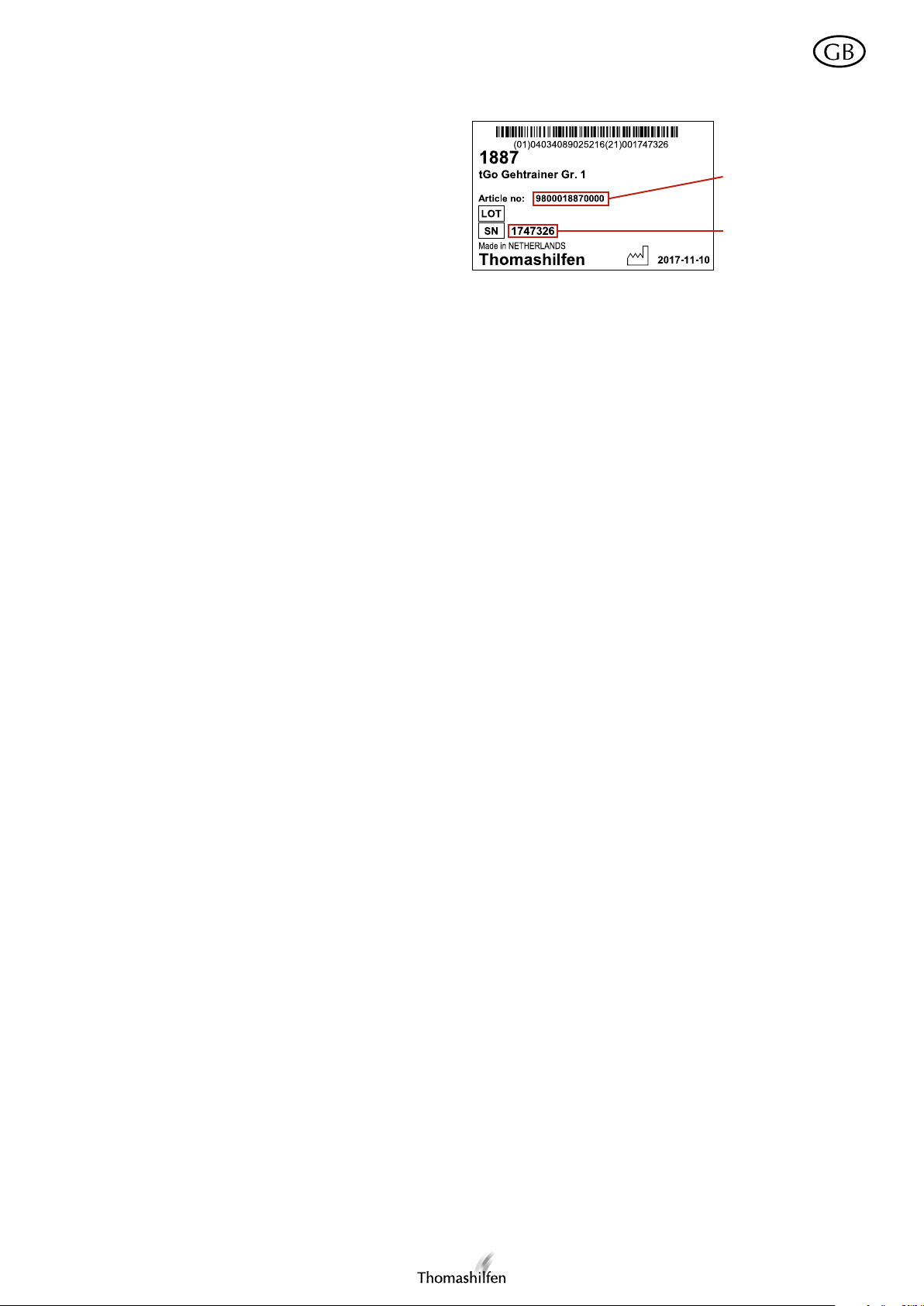
Product/serial number (references the year of manufacture)
To ensure you receive the correct replacement parts or for
potential technical product recalls we will always require
you to state the serial/batch number together with the exact
item number. The serial/batch number will allow you to
find out the year of manufacture of your tGo from us.
User manual – tGo
Item code
The serial/batch number and the item number of the tGo
can be found on the barcode label on the tGo subframe.
Serial / batch number
Notes on cleaning, disinfection and care
If necessary you can wipe down all parts of the tGo using a dampened cloth. Household cleaning agents and disinfectants can be used to remove more stubborn dirt.
Warranty conditions/CE marking
From the date of purchase Thomashilfen provides a 2-year warranty on all frame components. The warranty covers all claims that
impair the function of the tGo. Damage caused through improper use (e.g. overloading) and normal wear and tear is excluded. The
tGo complies with the requirements of international standard DIN EN ISO 11199-3 TZ 4.3 and carries the CE mark. We hope that
you enjoy using your tGo gait trainer.
Maintenance/reuse
Servicing and repairs to the gait trainer may only be carried out by a specialist dealership. The user of this rehabilitation
aid must ensure that the prescribed inspections/maintenance are/is performed regularly and at the correct intervals. If
damage is evident the user is under a duty to actively inform and to have the damage repaired immediately by specialist
personnel. Only original spare parts may be used for repairs (the list of replacement/spare parts can be found on the
download page of our website at www.thomashilfen.com).
The removal and fitting of spare parts may only be carried out by specialist personnel! If it becomes necessary to return
the tGo to your specialist dealership, please ensure that the chassis is properly and securely packed for transportation
purposes.
Familiarize yourself with the functions of the product. Should you not already know the product you must study the
operating instructions before carrying out any inspections. Clean the product before commencing with inspections. For
cleaning, observe the notes on cleaning, disinfection and care.
Subsequently check the tGo for damage/cracks in the frame – including the handlebars, the wheels (including the wheel
forks), the saddle, the brakes and all of the pad elements.
The tGo is suitable for reuse. However, this rehabilitation product is subject to exceptional stresses.
We have calculated the product’s service life – when used properly and in compliance with the service and main-
tenance schedule – to be 5 years, on the basis of market observations and the state of the art. Periods during which the
product is in storage at specialist dealerships is excluded.
With corresponding care and maintenance this product will also be reliable in operation for significantly longer than this
period.
Before reuse the product must always be carefully cleaned and disinfected. The condition of the product must be checked by trained specialist personnel for wear and damage. Any problems with the product must be rectified in order to
ensure that the tGo can continue to be used safely. In this context, observe the notes on safety. For reuse, the product
must be supplied with its operating instructions. If none are available, either request a copy from Thomashilfen or obtain
them from the download page of our website at www.thomashilfen.com
If the condition of the tGo is unsuitable for reuse it can be recycled at your local recycling facility.
21

Manual del usuario – tGo
Estimados usuarios de tGo,
muchas gracias por la confianza mostrada y por la compra del producto. Con su tGo ha adquirido un producto innovador de la firma Thomashilfen.
Por favor, lea este manual de instrucciones para que el manejo del tGo sea seguro, práctico y cómodo para usted y
especialmente para los niños.
Si a pesar de todo tiene dudas o problemas, diríjase a su comercio especializado o directamente a nosotros. Nos
gustaría llamarle la atención en este sentido sobre nuestra página web www.thomashilfen.com, en la que podrá obtener
información actualizada
Nuestra dirección: Thomas Hilfen für Körperbehinderte GmbH & Co. Medico KG ·
Walkmühlenstraße 1
D - 27432 Bremervörde · Germany
Phone: +49 (0)4761 886-63 or -68 ·
www.thomashilfen.com
Contenido Página
Condiciones de funcionamiento permitidas / Lugares de empleo ...................................................................... 22
Riesgos de uso y contraindicaciones ................................................................................................................ 22
Finalidad /Indicación ........................................................................................................................................ 23
Controles técnicos de seguridad e intervalos de mantenimiento ........................................................................ 23
Indicaciones de seguridad ................................................................................................................................ 23
Datos técnicos ................................................................................................................................................. 24
Equipamiento básico ........................................................................................................................................ 24
Accesorios. ...................................................................................................................................................... 24
Instalación y montaje ....................................................................................................................................... 25
Adaptación del andador al niño / Opciones de regulación ................................................................................ 26
Freno de estacionamiento ................................................................................................................................ 27
Freno de fricción .............................................................................................................................................. 27
Montaje de los accesorios ................................................................................................................................ 27
Número de producto / serie ............................................................................................................................. 29
Indicaciones de limpieza, desinfección y cuidado ............................................................................................ 29
Condiciones de la garantía / Identificación CE .................................................................................................. 29
Mantenimiento / Reutilización .......................................................................................................................... 29
Condiciones de funcionamiento permitidas / Lugares de empleo
Antes de utilizar el tGo por primera vez, debe ser instruido por un especialista capacitado.
Atención: El tGo está diseñado para una capacitación segura para el alumno exclusivamente para uso en interiores.
Gracias a su diseño es también especialmente apropiado para su empleo en viviendas.
Riesgos de uso y contraindicaciones
El uso adecuado evita cualquier riesgos en la utilización. No se conocen contraindicaciones.
22

Manual del usuario – tGo
Finalidad / Indicación
Ejercicio para andar o para aprender a andar en casos de...
• niños con desarrollo motriz alterado
• alteración del SNC (por trastornos o tras infecciones / tumores)
• estados postraumáticos / postinfecciosos con trastornos del aparato motriz y, en caso necesario
con descarga progresiva
• niños con trastornos motrices cerebrales (tetraparesia, diparesia, hemiparesia)
• niños con espina bífida
• enfermedades neurológicas
• lesiones cráneo-encefálicas
• enfermedades musculares (congénitas / adquiridas / progresivas)
• enfermedades metabólicas nerviosas, musculares u óseas
Controles técnicos de seguridad e intervalos de mantenimiento
Deben realizarse mensualmente controles de todos los controles de funcionamiento y tornillos de fijación por personal
especializado. Por favor, tenga en cuenta que hay que fijar los tornillos y palancas de bloqueo después de cada ajuste.
Preste atención a las siguientes indicaciones de seguridad
• Lea atentamente el manual de instrucciones antes del primer uso o haga que se lo lean en caso de tener dificultades
de lectura. En caso de que se haya perdido el manual de instrucciones, puede descargarlo en cualquier momento en
el área de descargas de nuestra página web www.thomashilfen.com.
• Le aconsejamos adaptar los ajustes del tGo a las dimensiones corporales del niño como mínimo cada tres meses.
Esto debería hacerse, en caso necesario, con la ayuda de su terapeuta / ortopedista
• No deje nunca al usuario del tGo en el andador sin vigilancia!
• Debe comprobarse el funcionamiento correcto del freno de estacionamiento antes de cada utilización del tGo. En
caso de que el freno no funcione correctamente, no debe utilizarse el tGo. Póngase en contacto con su vendedor
especializado para subsanar el problema.
• ATENCIÓN: Debe prestarse atención a que no se introduzca ninguna extremidad en el espacio entre la rueda y la
horquilla.
• ATENCIÓN: Tenga en cuenta que durante los ajustes y regulaciones del tGo existe un peligro mayor de enganche.
• ATENCIÓN: Las ruedas mojadas pueden influir en la eficacia del freno. En caso de una parada prolongada de-
beríaasegurar el tGo con el freno de estacionamiento para evitar desplazamientos involuntarios.
• El andador debería utilizarse únicamente sobre una superficie plana, horizontal y sólida. Preste atención a irregularidades y agujeros en el suelo. Existe el peligro de volcar o atascarse.
• No deben fijarse bolsas pesadas u otros objetos al tGo, ya que aumenta el peligro de vuelco.
• Mantenga alejados a los niños del envoltorio, existe peligro de asfixia.
• Si se extraen partes de los accesorios, pueden quedar terminaciones de tubos abiertas. En ocasiones, éstas pueden
tener bordes interiores afilados e implican peligro de lesiones en los dedos si se introducen en dichas aberturas. No
obstante, el tGo y sus accesorios están concebidos de tal modo que se eviten estos riesgos. Si aún así, estas terminaciones de tubos representasen un peligro, pueden cubrirse con tapones de plástico.
• Los elementos de almohadillado no deben consumirse.
23

Manual del usuario – tGo
Datos técnicos
tGo 1 tGo 2
Altura de asiento 250 mm - 600 mm 250 - 800 mm
Dimensiones totales (L x A) 830 x 540 mm 920 x 650 mm
Altura del asidero 430 - 900 mm 450 - 1100 mm
Altura del soporte pélvico 400 - 750 mm 400 - 950 mm
Tamaño de ruedas delanteras 150 mm 150 mm
Tamaño de ruedas traseras 200 mm 200 mm
Peso 12.4 kg 13.8 kg
max. Capacidad de carga 40 kg 45 kg
Equipamiento básico
El tGo se envía en su configuración básica con los siguientes componentes:
• bastidor inferior con freno de estacionamiento y freno de fricción
• asidero regulable en altura y ángulo
• sillín orientable (regulable en altura e inclinación)
• almohadillas para el pecho (5 elementos), pelvis (5 elementos) y tronco (3 elementos)
• cinturón para las almohadillas de pecho
• llave Allen con 2 lados de diferentes tamaños
• rueda delantera orientable con bloqueo de dirección
Accesorios
Hay disponibles los siguientes accesorios para el tGo:
• sistema de frenado de asiento
• panel de separación de piernas
• almohadillas complementarias
• empuñaduras separadas
• empuñadura vertical
• bloqueo de retornol
• barra de arrastre
24

Manual del usuario – tGo
Instalación y montaje
El tGo está separado en piezas a la entrega. Siga los pasos uno a uno para montar el tGo:
1. Introducir el tubo central grueso en el alojamiento del bastidor inferior de tal modo que los orificios en el tubo se
alineen con los del alojamiento (fig. 1) Introducir los tornillos Allen incluidos, desde la parte interior del bastidor, a
través del alojamiento del bastidor y el tubo central (fig. 2).
2. Tomar la anilla de plástico con la tuerca premontada y sujetarla en la parte frontal del tGo contra los orificios del
bastidor en los que se introducen los tornillos Allen. Atornillar los tornillos en la tuerca de la anilla de plástico. Aseguresé de que el tubo central y el bastidor están firmemente unidos entre sí (fig. 3).
3. En el extremo inferior del tubo central hay un casquillo negro de plástico. Apriete ambos tornillos Allen desde abajo.
Preste atención a efectuar un mínimo de 15 giros a cada tornillo. (fig. 4)
4. A continuación afloje el tornillo Allen atornillado en el lado del elemento delantero del brazo articulado central.
Introducir el brazo articulado en el tubo central de modo que el brazo señale la parte interior del bastidor y la parte
curvada del elemento metálico quede hacia arriba. Alinear el brazo articulado con la parte frontal del bastidor inferior y fijarlo con los tornillos Allen colocados en el elemento anterior (fig. 5). Aseguresé de que el tubo central y el
brazo articulado están firmemente unidos entre sí y que el brazo articulado no se desliza hacia abajo al cargar peso.
5. Aflojar la tuerca inferior que se encuentra en la varilla roscada bajo el sillín. Introducir la varilla roscada en el orificio
más adelantado de los dos orificios de alojamiento del elemento trasero del brazo articulado (fig. 6). Delante del
sillín se encuentra un tubo que apunta hacia arriba. Ponga atención a que el sillín se introduzca en el alojamiento
con el tubo en la dirección de marcha. Volver a enroscar la tuerca que se quitó bajo el brazo articulado en la varilla
roscada. Tenga cuidado de que el anillo de goma de la tuerca señale hacia arriba (fig. 7). Apretar la tuerca.
6. Tomar el manillar. Aflojar los tornillos Allen de la articulación en el extremo superior del tubo del manillar. Para ello
debe aflojarse la palanca de sujeción y el manillar debe colocarse en una posición tal que el orificio del alojamiento
del manillar coincida con la perforación longitudinal del tubo del manillar (fig. 8). Ahora puede introducirse la parte
alargada de la llave Allen en el tubo hasta que agarre el tornillo (fig. 9). Aflojar el tornillo.
7. Introducir el tubo del manillar en el tubo central del tGo (fig. 10). Puede girar el manillar 360º en el tubo central. De
este modo puede elegir si el brazo del alojamiento del manillar queda hacia adelante (fig. 11) o hacia atrás (fig. 12).
A continuación alinear el manillar paralelo a la parte frontal del tGo. Fijar el manillar enroscando fuertemente los
tornillos Allen en el tubo del manillar. Coloque el manillar en la posición deseada y fíjelo con la palanca de sujeción
(fig. 13). Bloquear la palanca de sujeción con la corredera incorporada.
8. Fijar las almohadillas pélvicas en el tubo delante del sillín. Para ello debe soltarse el tornillo en el alojamiento del
tubo. Los tornillos Allen que unen cada una de las almohadillas deben tener la cabeza hacia arriba. Enroscar fuertemente el tornillo en el alojamiento del tubo para fijar las almohadillas (fig. 14).
9. Aflojar el tornillo del tubo de las almohadillas de pecho para el montaje de éstas. Introducir el tubo en el tubo delante del sillín del tGo de tal modo que las almohadillas de pecho queden situadas por encima de las almohadillas
pélvicas (fig. 15). Fijar el tubo apretando los tornillos del interior.
10. Para el montaje de las almohadillas de tronco, aflojar la palanca de sujeción de la parte posterior Desplazar el tubo
del apoyo de tronco desde atrás sobre el tubo en el que está colocado el sillín. Fijar el apoyo de tronco con la palanca de sujeción (fig. 16).
25

Manual del usuario – tGo
Adaptación del andador a los niños / Opciones de regulación
Los ajustes / adaptaciones deben llevarse a cabo básicamente por personal especializado formado o instruido (p. ej.
asesores de productos médicos del sector comercial sanitario).
Ajuste de altura del sillín
1. Ajustar primero la altura del brazo articulado en el tubo central. Para hacerlo, soltar el tornillo lateral del elemento
frontal del brazo articulado y desplazar el brazo en altura (fig. 17). Después del ajuste, fijar el brazo articulado con
el tornillo en el elemento más adelantado. Aseguresé de que el tubo central y el brazo articulado están firmemente
unidos entre sí y que el brazo articulado no se desliza hacia abajo al cargar peso.
2. El ajuste preciso de la altura e inclinación del sillín se realiza por medio de la articulación del brazo articulado y la
varilla roscada bajo el sillín. Para la regulación del ángulo de la articulación, soltar los tornillos situados en la superficie negra de la parte superior de la articulación (fig. 18). Colocar el brazo articulado en la posición deseada y fijarlo
a la parte superior de la articulación apretando los tornillos.
3. Para la regulación de la altura del sillín por medio de la varilla roscada bajo el sillín, girar la tuerca de la varilla por
encima del brazo articulado hacia arriba (bajará la altura del sillín) o hacia abajo (subirá la altura del sillín) (fig. 19).
Cuando haya ajustado a la altura deseada, fije la altura del sillín girando hacia arriba bajo el brazo articulado lo
máximo posible y apretando (fig. 20).
Variación de la posición del sillín
El sillín puede montarse en dos posiciones diferentes para variar la separación con el manillar. Proceda como se describe a continuación:
1. Aflojar la tuerca inferior que se encuentra en la varilla roscada bajo el sillín. Introducir la varilla roscada en el orificio
del alojamiento anterior o posterior del elemento trasero del brazo articulado (Ilus. 6). Delante del sillín se encuentra
un tubo que apunta hacia arriba. Ponga atención a que el sillín se introduzca en el alojamiento con el tubo en la
dirección de marcha.
2. Volver a enroscar la tuerca que se quitó bajo el brazo articulado en la varilla roscada. Tenga cuidado de que el anillo
de goma de la tuerca señale hacia arriba (Ilus. 7). Apretar la tuerca.
Ajustar el manillar
1. Regule primero la altura del manillar soltando el tornillo Allen de la articulación en el extremo superior del tubo del
manillar. Para ello debe aflojarse la palanca de sujeción y el manillar debe colocarse en una posición tal que el orificio del alojamiento del manillar coincida con la perforación longitudinal del tubo del manillar (fig. 8). Ahora puede
introducirse la parte alargada de la llave Allen en el tubo hasta que agarre el tornillo (fig. 9).
2. Desplazar ahora el tubo del manillar en el tubo central del tGo hasta alcanzar la posición deseada. Ponga atención
al hacerlo a la marca hasta la que puede sacarse como máximo el tubo del manillar. Puede girar el manillar 360º en
el tubo central. De este modo puede elegir si el brazo del alojamiento del manillar queda hacia adelante (fig. 11) o
hacia atrás (fig. 12). A continuación alinear el manillar paralelo a la parte frontal del tGo. Fije manillar enroscando
fuertemente los tornillos Allen en el tubo del manillar.
3. Coloque el manillar en la posición deseada (fig. 21) y fíjelo con la palanca de sujeción (fig. 13). Bloquear la palanca
de sujeción con la corredera incorporada.
Adaptación de la altura de las almohadillas
1. Las almohadillas pélvicas pueden regularse en altura. Para ello debe soltarse el tornillo en el alojamiento del tubo.
Las almohadillas pélvicas pueden desplazarse ahora en altura por el tubo. Volver a enroscar fuertemente el tornillo
en el alojamiento del tubo para fijar las almohadillas (fig. 14).
2. Las almohadillas de pecho pueden regularse en altura en el tubo en el que están colocadas. Para hacerlo, aflojar el
tornillo en el extremo superior del tubo de las almohadillas pectorales (fig. 22) y desplazar verticalmente el tubo.
Para fijar las almohadillas pectorales, vuelva a apretar el tornillo.
3. Las almohadillas de tronco pueden regularse en altura. Para ello debe soltarse el tornillo en el alojamiento del tubo
(fig. 23). Las almohadillas de tronco pueden desplazarse ahora en altura por el tubo. Volver a enroscar fuertemente
el tornillo en el alojamiento del tubo para fijar las almohadillas.
26

Manual del usuario – tGo
Función de las almohadillas de tronco
Para facilitar el acceso del niño en el tGo, las almohadillas de tronco pueden soltarse rápidamente mediante la palanca
de sujeción y desplazarse hacia atrás. También pueden desplazarse hacia abajo por medio de la palanca de sujeción.
Tenga cuidado de volver a fijar la palanca de sujeción después de cada regulación.
Ajuste del cinturón
El cinturón puede regularse en longitud por medio de la hebilla corredera (fig. 28). El cierre de velcro al final del cinturón sirve para poder abrirlo o cerrarlo. (fig. 27)
Atención: El cierre de velcro debe estar completamente cerrado, cuando el niño se encuentre en el tGo.
Adecuación del número de almohadillas
Puede adecuar de forma flexible el número de almohadillas a las necesidades del niño. Para ello vea el punto „elementos de protección adicionales“ en la sección del montaje de accesorios de estas instrucciones.
Bloquear / soltar la función de giro del sillín
Para cambiar entre la función giratoria del sillín y la posición fija, hay que sacar al niño del tGo. A continuación desmontar el sillín del tGo. Quitar el tornillo Allen y la arandela del extremo inferior de la varilla roscada del sillín. Entonces puede sacar hacia abajo la varilla roscada. La varilla roscada está provista de dos muescas de forma diferente en sus
dos extremos. Cuando se introduce la varilla en el alojamiento con el corte en ángulo recto hacia arriba el sillín está en
posición fijado. La función de giro está desactivada.
Cuando la varilla se introduce en el alojamiento con la otra cara hacia arriba, la función de giro está activada. Después
del ajuste vuelva a montar el sillín en el tGo (para el montaje, vea instalación y montaje, sección 4).
Freno de estacionamiento
Para bloquear el freno de estacionamiento, pliegue hacia abajo las palancas rojas (fig. 24), que se encuentran en la parte inferior
del bastidor, delante de las ruedas, de modo que bloqueen las ruedas (fig. 25). Para desbloquear el freno de estacionamiento se
levantan las palancas.
Freno de fricción
El freno de fricción se acciona mediante el mecanismo de regulación rojo en la parte superior del bastidor, delante de
las ruedas traseras. Hay una marca junto al punto rojo de regulación. Cuando señala en la dirección de avance, el freno
de fricción está desbloqueado.
Puede accionarse en cinco pasos mediante una llave Allen. Para ello gire el punto de regulación rojo en sentido contrario a las agujas del reloj (fig. 26). Cuando se ha sobrepasado la quinta posición, la marca señala nuevamente la dirección de avance; el freno de fricción está desactivado.
Montaje de los accesorios
Incorporación y ajuste de mangos verticales
Montaje
Para montar los mangos verticales (disponibles como accesorios), es necesario cambiar el manubrio del equipamiento
básico. Retire el revestimiento de espuma en un lado del manubrio (quítelo del manubrio correspondiente al equipamiento básico). (Fig. 30) Con la ayuda de un destornillador, afloje el pequeño tornillo plástico en el apoyo del manubrio
(Fig. 31) y póngalo a un lado. Quite el tubo del manubrio pasando el lado sin revestimiento de espuma a través del
anillo situado en el apoyo. Afloje el tornillo hexagonal en uno de los cuernos. Retire el cuerno y desplace el manubrio
a través del anillo del apoyo de forma tal que el tornillo del alojamiento de la empuñadura quede orientado hacia fuera
del tGo. (Fig. 32) Vuelva a ajustar bien el tornillo en el apoyo del manubrio. Coloque el cuerno en el manubrio, verificando que el tornillo de fijación quede orientado hacia fuera del tGo. Apriete bien el tornillo. (Fig. 33) Antes de usar,
compruebe que los tornillos estén bien ajustados.
27

Manual del usuario – tGo
Panel de separación de piernas
El panel de separación de piernas se fija en el elemento más trasero del brazo articulado, en el que también se coloca
el sillín. Monte opcionalmente el panel separador de piernas en los orificios de alojamiento delantero o trasero del
elemento más trasero del brazo articulado. Para montar el panel separador de piernas debe quitarse el sillín. Introducir
el panel separador de piernas desde abajo en uno de los orificios de alojamiento del brazo articulado. Asegurar el panel
separador de piernas con el tornillo Allen. Vuelva a montar el sillín en el tGo (para el montaje vea instalación y montaje, sección 4).
Elementos de protección adicionales
El número de almohadillas del tGo puede configurarse individualmente. Para la colocación de más almohadillas, primero debe retirarse el elemento de plástico negro que tiene una ranura para el cinturón. Para ello, quite el tornillo que une
la almohadilla exterior con el elemento de plástico (serán necesarias la llave Allen proporcionada y una llave en estrella
o llave fija del 10).
Extraiga el elemento de plástico negro de la almohadilla. Introduzca discrecionalmente varias almohadillas en el anillo
para almohadillas. Tenga en cuenta que el soporte de plástico negro de las almohadillas está dirigido en sentido contrario al cuerpo del niño. Fijar las almohadillas con los tornillos y tuercas proporcionados. A continuación volver a colocar
y fijar los elementos para la guía del cinturón en el soporte de las almohadillas. Para desmontar las almohadillas no
necesarias, proceda de un modo análogo.
Incorporación y ajuste del sistema de freno del asiento
Montaje
Para montar el sistema de freno del asiento, es necesario cambiar las ruedas traseras del equipamiento básico por las
ruedas traseras con sistema de freno de asiento integrado (disponibles como accesorios). Esta tarea debe ser realizada
únicamente por personal especializado. Para ello, hay que quitar los respectivos tornillos hexagonales, a través de los
cuales se fija el bastidor del tGo a la rueda. (Fig. 36) Ahora es posible cambiar las ruedas estándar por las ruedas con
sistema de freno de asiento integrado.Durante el montaje, asegúrese de que la suspensión quede perpendicular al suelo.
(Fig. 38) Por medio de los tornillos hexagonales, fije las ruedas al armazón del tGo.
Si usted se encuentra al cuidado de un niño de muy bajo peso, puede ser necesario quitar un resorte del sistema de
freno del asiento. Para ello, extraiga los dos tornillos Allen de la rueda. Ponga a un lado la tapa, quite uno de los pernos
metálicos y retire el resorte. (Fig. 37) Vuelva a colocar el perno sin el resorte en el dispositivo. Verifique que el resorte
del otro perno quede tenso en la abertura. Fije nuevamente la tapa, con la curvatura orientada hacia abajo. Antes de
usar, compruebe que los tornillos estén bien ajustados.
Incorporación y ajuste del bloqueo de retorno
Montaje
Para montar el bloqueo de retorno, es necesario cambiar las ruedas traseras del equipamiento básico por las ruedas
traseras con bloqueo de retorno integrado (disponibles como accesorios). Esta tarea debe ser realizada únicamente
por personal especializado. Para ello, hay que quitar los respectivos tornillos hexagonales, a través de los cuales se fija
el bastidor del tGo a la rueda. (Fig. 36) Ahora es posible cambiar las ruedas estándar por las ruedas con bloqueo de
retorno integrado. Monte las ruedas de forma tal que la parte convexa de plástico (Fig. 34) quede orientada hacia la
izquierda. Inserte en este lado el manguito distanciador metálico más pequeño. Monte la rueda en el otro lado con el
manguito distanciador metálico más grande. (Fig. 35) Por medio de los tornillos hexagonales, fije las ruedas al armazón
del tGo. Antes de usar, compruebe que los tornillos estén bien ajustados.
Barra de arrastre
La barra de arrastre puede engancharse en caso necesario en la anilla de plástico del bastidor inferior (fig. 29).
28

Manual del usuario – tGo
Número de producto / serie (Referencia al año de fabricación)
Para recibir las piezas de repuesto correctas o para consultas técnicas necesitamos básicamente los datos de número
de serie y lote y el número de artículo exacto. Mediante el
número de serie y lote puede obtener el año de fabricación
de su tGo.
Los números de serie y lote, así como el número de artículo del
tGo, se encuentran en la etiqueta de código de barras colocada
en el bastidor inferior.
Número de artículo
Número de serie /
lote
Indicaciones de limpieza, desinfección y cuidado
Puede limpiar todas las piezas del tGo con un paño suave y, cuando sea necesario, húmedo. Para la suciedad resistente
puede emplearse cualquier otro producto de limpieza doméstico o desinfectante.
Condiciones de la garantía / Identificación CE
Thomashilfen le ofrece 2 años de garantía a partir de la fecha de compra para todas las piezas del cuadro. La garantía
cubre todas las reclamaciones que afecten al funcionamiento. Están excluidos los daños que se produzcan por un
manejo inadecuado (p. ej. sobrecarga), así como el desgaste natural. El tGo cumple los requisitos de la norma internacional DIN EN ISO 11.199 Subs. 4.3 y está avalado por una identificación CE. ¡Le deseamos que disfrute con su andador
tGo!
Mantenimiento / Reutilizacion
El servicio y reparaciones del andador sólo deben ser realizadas por un comercio especializado. El usuario de este medio auxiliar de rehabilitación tiene que prestar atención a que se lleven a cabo las inspecciones y el mantenimiento prescrito regularmente y cuando corresponda. Si se detecta un daño, el usuario debe informar rápidamente y hacer reparar
el daño inmediatamente por personal especializado. Para las reparaciones deben emplearse exclusivamente piezas de
repuesto originales (la relación de las piezas de recambio o sustitución la puede encontrar en el área de descargas de
nuestra página webwww.thomashilfen.com).
El desmontaje y montaje de los repuestos sólo puede ser realizado por personal especializado! En caso de ser necesaria
la devolución a su comercio especializado, ponga cuidado en embalar el vehículo de forma segura para el transporte.
Familiarícese con las funciones del producto. Si no conoce el producto, estudie el manual de instrucciones antes de
probarlo. Limpie el producto antes de comenzar a probarlo. Tenga en cuenta para ello las indicaciones de limpieza,
desinfección y cuidado.
A continuación compruebe el tGo en lo relativo a daños / grietas en el armazón incluido manillar, ruedas y horquilla,
sillín, frenos y todos los problemas de almohadillas.
El tGo puede reutilizarse. No obstante este producto de rehabilitación está sometido a un esfuerzo extraordinario.
Basándonos en las observaciones del mercado y el estado de la tecnología, hemos calculado el periodo de vida del
producto en 5 años, haciendo un uso adecuado y cumpliendo las labores de mantenimiento y servicio. Se excluyen los
tiempos de almacenamiento en los comercios especializados.
Con un cuidado y mantenimiento adecuados, el producto sigue siendo fiable sobrepasado ampliamente este plazo.
Para volver a utilizar el producto es básico limpiarlo siempre en profundidad y desinfectarlo. El estado relativo al
desgaste y los desperfectos, debe evaluarse por personal especializado instruido. Las objeciones deben ser subsanadas
para seguir garantizando un uso seguro del tGo. Tenga en cuenta para ello las indicaciones de mantenimiento. Debe
acompañarse un manual de instrucciones al producto para la reutilización del mismo. Si no se dispusiese de ninguno,
solicítelo a Thomashilfen o descárgelo del área de descargas de muestra página web www.thomashilfen.com.
Si el tGo no puede reutilizarse a causa de su estado, puede reciclarse por la empresa de eliminación.
29

Manual usuário – tGo
Caro utilizador do tGo
Agradecemos a confiança depositada ao adquirir o nosso produto. Com o seu tGo adquiriu um produto inovador da
série Thomashilfen.
Leia primeiro estas instruções de utilização para que a utilização do tGo seja fácil, prática e confortável, para si e especialmente para a criança.
Em caso de dúvidas ou qualquer problema, entre em contacto com o revendedor autorizado ou connosco. Chamamos
a sua atenção para a nossa página na internet www.thomashilfen.com onde pode consultar toda a informação atualizada.
O nosso endereço : Thomas Hilfen für Körperbehinderte
GmbH & Co. Medico KG
Walkmühlenstraße 1
D - 27432 Bremervörde
Tel: +49 (0)4761 886-63 or -68
www.thomashilfen.com
Índice Página
Condições de utilização permissíveis / local de utilização ................................................................................ 30
Riscos de utilização e contraindicações ............................................................................................................ 30
Finalidade / Indicação ...................................................................................................................................... 31
Controlos de segurança e intervalos de manutenção ........................................................................................ 31
Devem ser impreterivelmente observadas as seguintes instruções de segurança ............................................... 31
Características técnicas .................................................................................................................................... 32
Estrutura básica ................................................................................................................................................ 32
Acessórios ....................................................................................................................................................... 32
Instalação e montagem .................................................................................................................................... 33
Adaptação do andarilho à criança / opções de ajuste ....................................................................................... 34
Travão de bloqueio de marcha ......................................................................................................................... 35
Travão de fricção ............................................................................................................................................. 35
Montagem dos acessórios ............................................................................................................................... 35
Produto / número de série ............................................................................................................................... 37
Instruções de limpeza, desinfeção e tratamento ................................................................................................ 37
Garantia / marcação CE ................................................................................................................................... 37
Manutenção / reutilização ................................................................................................................................ 37
Condições de utilização permissíveis / local de utilização
Antes que o tGo seja usado pela primeira vez, ele deve ser instruído por um especialista treinado.
Atenção: O tGo é projetado para treinamento seguro para caminhantes apenas para uso interno. Graças ao seu design,
é especialmente apropriado para utilização dentro de casa.
Riscos de utilização e contraindicações
A devida utilização exclui potenciais riscos durante o emprego deste produto. Desconhecem-se quaisquer contraindicações.
30
 Loading...