

Page 1
TM
1 of 2
—
OPERATING INSTRUCTIONS
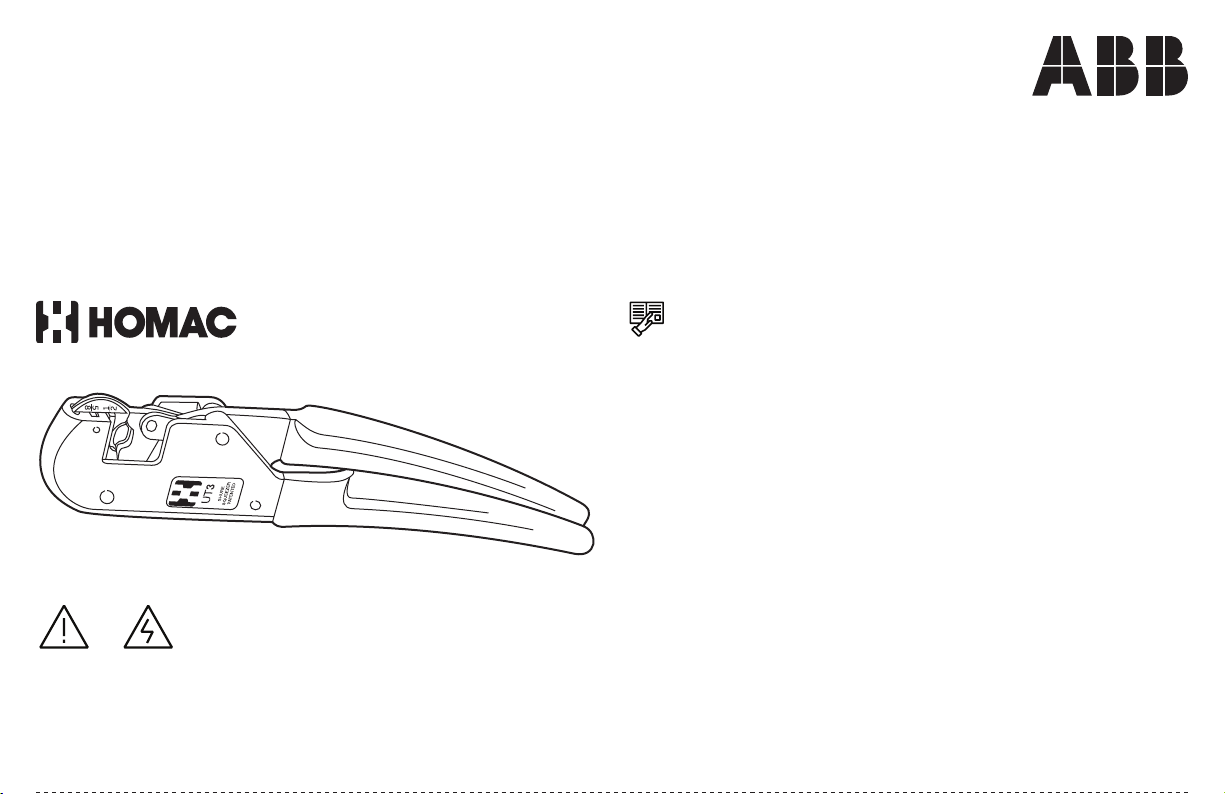
Installing tool, UT 3
For all " and " compression connectors
Important
Read and understand all instructions and
safety information in this manual before
operating or servicing this tool. Be aware of
proper usage and potential hazards.
This lightweight (35 ounces) pocket size tool features SHURE-SQUEEZER™ DESIGN a proven ratchet and pawl mechanism which is designed to deliver proper
compression before the jaws will release.
It installs the complete range of " and " self-insulated and bare SHURE-SPLICER™
WARNING:
• Risk of shock, disconnect power before installation.
CAUTION:
• Product should be operated by a qualified electrician in
accordance with national and local electrical codes.
service connectors, in addition to one and two hole lugs, pin terminals, tees, splices
and the UB212 and UB214 street lighting tap, simply by removing and reversing the
coded upper die in the tool head.
Installation time is quicker because one stroke of the tool develops a full
circumferential compression.
The tool frame is precision cast of steel with plastisol cushioned handles.
Because the tool has relatively few moving parts, maintenance consists of an
occasional oiling of pivot and link pin areas.
Page 2

Lubricate
Figure A Figure B Figure C
Tolerance gauge
Figure D
Index no.
2 of 2
Instructions
Lubrication:
The tool should be oiled occasionally with a
good grade of lubricating oil in the pivot and
link pin areas.
Installing dies:
This tool installs all " and " compression connectors. Install both sizes quickly by
removing and reversing the upper die for either size. To install the ½" sizes, the die
should be in the position shown in Figure B (" is readable, the " is upside down). To
install " sizes, pull the upper die straight out of the tool, reverse the die and re-insert
into tool. The " is now readable as shown in Figure C.
2
1 2
1
UT3-4G
5
8
1. Install by inserting
die into tool head.
2. Pull out to remove.
8
5
8
5
1
UT3-4G
1
2
2
Tool compression test:
To test for proper compression, place the
"tolerance gauge" between the dies and close
the tool. If the gauge is not held in place, the
tool is below tolerance and should be returned
to the factory for repair, Figure D.
—
For parts or service, contact Tool Service Center at:
Phone: 1-800-284-TOOL (8665)
Webpage: electrification.us.abb.com/tool-service
—
tnb.abb.com (US/Latin America)
tnb.ca.abb.com (Canada)
abb.com
Warranty: tnb.abb.com/toolregistration
—
We reserve the right to make technical
changes or modify the contents of this document without prior notice. With regard to
purchase orders, the agreed particulars shall
prevail. ABB does not accept any responsibility whatsoever for potential errors or possible
lack of information in this document.
Part list
Overall dimensions: 12" x 2 ½" x ¾"
Weight: 2 lbs. 3 oz.
1
2
3
Product selection
Part no: Index
Description
No.
UT 3-1 1 Frame
UT 3-12 2 Nest spring
UT 3-4G 3 Nest
UT 3-10 4 Indentor pivot pin
2
UT 3-3 5 Indentor
1
2
1
5
8
UT 3-5 6 Link
5
8
UT 3-11 7 Link pin
UT 3-9 8 Handle pivot pin
4
5
6
7
8
9
10
11
12
13
14
UT 3-2 9 Movable handle
UT 3-14 10 Groove pin
UT 3-8 11 Washer
UT 3-13 12 Pawl pin
UT 3-6 13 Pawl
UT 3-7 14 Extension spring
Note: Product must be operated in
accordance with applicable national and local
electrical codes.
We reserve all rights in this document and in
the subject matter and illustrations contained
therein. Any reproduction – in whole or in part
– is forbidden without prior written consent
of ABB. © 2022 ABB Installation Products Inc.
and/or its related companies. All Rights
Reserved.
Installing tool, UT 3 | Operating Instructions | 102_R5 | 0014639 BInstalling tool, UT 3 | Operating Instructions | 102_R5 | 0014639 B
 Loading...