

Page 1
Gas-Fired T ubular,
Radiant, Low-Intensity
Infrared Heater
®
INST ALLA TION FORM RZ-NA-I-TR
Obsoletes Form 456 (Version B)
APPLIES TO: INFRA-REZ® Heater Models TR/TR-H
Table of Contents
Paragraph No. Page Paragraph No. Page
GENERAL................................................................................................. 1
HEATER INSTALLATION............................................................... 1-21
1A. Installation Codes ............................................................................... 2
1B. Warranty .............................................................................................. 2
2. Description/General .............................................................................. 2
3. Specifications ........................................................................................ 3
4. Clearances to Combustibles ................................................................. 3
5. Location and Mounting Height .......................................................3- 4
6. Uncrating/Packaging ............................................................................ 4
7. High Altitude Operation ....................................................................... 5
8. Suspension Dimensions and Preparation ........................................... 5
9. Prepare and Install Burner/Control Box and
Combustion Chamber Tube ......................................................... 6-8
10. Install the Heat Exchanger Tube(s), Tail Pipe
Tube, and Turbulator Strip ....................................................... 8-11
11. Install Reflectors (including Standard Reflectors, Optional
Side Shield, and Optional Reflector Gap and End Covers) ..... 1 2
REFERENCES: Operation/Maintenance/Service Manual, Form RZ-NA-O-TR
Suspension Dimensions and Configuration Drawings Booklet, Form RZ-NA 607
Replacement Parts Manual, Form RZ-NAP-VR/TRP/TR
12. Venting ........................................................................................ 13-17
13. Combustion Air ................................................................................ 17
14. Gas Piping and Pressures .......................................................... 17-19
15. Electrical Supply and Connections .......................................... 19-20
16. Check Installation and Start-Up ..................................................... 2 1
OPTIONAL EQUIPMENT - Field Installed ................................ 22-23
17. Optional Heat Exchanger Tubes ("U", "L", 5-ft) ......................... 22
18. Hanger Kit, Option CK11 ............................................................... 22
19. Turnbuckle Kit, Options CK12-18 ................................................ 22
20. Combustion Air Inlet Kit, Option DE2 ......................................... 2 3
21. Dual Vent Kit, Option CC5 ............................................................. 23
22. Optional Side Shield, Options CD13-20 ....................................... 23
23. Optional Reflector Gap and End and Gap Covers ...................... 2 3
24. Multiple Heater Control, Options CL31 and 32 .......................... 23
25. Optional Unit-Mounted Thermostat Bracket Kit,
Option CM3 ................................................................................... 23
Index......................................................................................................... 24
FOR YOUR SAFETY
If you smell gas:
1. Open windows.
2. Don't touch electrical switches.
3. Extinguish any open flame.
4. Immediately call your gas supplier.
FOR YOUR SAFETY
The use and storage of gasoline or other
flammable vapors and liquids in open
containers in the vicinity of this appliance is
hazardous.
WARNING: Improper installation, adjustment, alteration, service, or maintenance can
cause property damage, injury or death.
Read the installation, operation, and
maintenance instructions thoroughly before
installing or servicing this equipment.
WARNING: Gas-fired appliances are not
designed for use in hazardous atmospheres containing
flammable vapors or combustible dust, in
atmospheres containing chlorinated or halogenated
hydrocarbons, or in applications with airborne
silicone substances. See Hazard Levels, Page 2.
GENERAL
Installation should be done by a qualified agency in accordance with the instructions in this manual and in compliance with all codes and requirements of
authorities having jurisdiction. The instructions in this manual apply to the
heater models shown below .
Model Characteristics
TR Indoor, Gas-Fired,
Low-Intensity
Infrared Tubular
System, 0-2000 ft
(0-610M) elevation
TR-H Indoor, Gas-Fired,
Low-Intensity Infrared
Tubular System,
for 2001-8000 ft
(611-2438M) elevation
Form RZ-NA-I-TR, Mfg No. 121027 Rev 5,
Page 1
Page 2

HAZARD INTENSITY LEVELS
1. DANGER: Failure to comply will result in severe personal injury or death and/or property damage.
2. WARNING: Failure to comply could result in severe personal injury or death and/or property dam-
age.
3. CAUTION: Failure to comply could result in minor personal injury and/or property damage.
1A. Installation Codes
These units must be installed in accordance with local building codes.
In the absence of local codes, in the United States, the unit must be
installed in accordance with the National Fuel Gas Code ANSI Z223.1a
(latest edition). A Canadian installation must be in accordance with the
CAN/CGA B149.1 and B149.2 Installation Code for Gas Burning
Appliances and Equipment. These codes are available from CSA Information Services, 1-800-463-6727. Local authorities having jurisdiction should be consulted before installation is made to verify local
codes and installation procedure requirements.
All electrical wiring must be in accordance with the National Electric
Code ANSI/NFPA NO. 70 (latest edition) or, in Canada, the Canadian
Electrical Code, part I-C.S.A. Standard C22.1.
The installing contractor must be familiar with all of the various requirements and is responsible for installing this heater in compliance
with the applicable codes.
Special Installations --
Aircraft Hangars: In the United States, the heaters must be installed
in accordance with ANSI NFPA 409 (latest edition), Chapter 5. NFP A
Publications are available from the National Fire Protection Association, Batterymarch Park, Quincy , MA 02269. In Canada, installation
in an aircraft hangar must comply with CAN/CGA-B149.2, Section
4.21. Both ANSI NFPA 409 and the CAN/CGA-B149.2 specify that
the heater shall not be located in an area of an aircraft hangar where it
may be subjected to physical damage by aircraft, cranes, moveable
scaffolding, or other objects.
NFP A 409 specifies a c learance of 10 feet to the bottom of the heater
from the highest surface of the wings or engine enclosures of the
highest aircraft which may be housed in the hangar. CAN/CGA B149.2
specifies that an infrared heater installed in an aircraft hangar be at least
10 ft (3m) above either the highest fuel storage compartment or the
highest engine enclosure of the highest aircraft which may occupy the
hangar. NFPA 409 and CAN/CGA B149.2 specify a minimum clearance of eight feet from the floor to the heater in other sections, such as
offices, or shops, that communicate with the aircraft hangar .
Public Garages: In the United States, heaters installed in public garages must be in accordance with National Fire Protection Association
(NFP A) 88B (latest edition), Section 3-2.3. Overhead heaters must be
located not less than eight feet above the floor and installed in accordance with the conditions of their approval. NFPA 88B requires the
following warning:
W ARNING: Minimum clearance marked on the
heater must be maintained from vehicles parked
under the heater .
In Canada, in a garage, the minimum clearance from the bottom of an
infrared heater to the upper surface of the highest vehicle which may be
housed therein shall be 50 percent greater than the certified clearance,
and in no case less than eight feet (2.4m).
W ARNING: These tubular radiant heaters DO
NOT qualify f or explosion-proof installations.
WARNING: The installing contractor must be
certain that the area where the heater is being
installed does not contain corrosive or toxic fumes
or that elements in the atmosphere do not produce
corrosive or toxic fumes in the presence of an open
flame.
The chlorine atmosphere in enclosed swimming
pool areas may cause burner and tube corrosion if
the area is not ventilated. ASHRAE design guides
suggest a minimum of 5-6 air changes per hour.
The manufacturer recommends outside
combustion air . T o pro vide outside combustion air ,
Option DE2, Combustion Air Inlet Kit, must be
used.
1B. Warranty
Refer to limited warranty information on the warranty sheet in the "Owner's
Envelope".
2. Description/General
These radiant tubular heaters are low-intensity infrared heaters using a
power burner that fires into a 4" diameter steel tube, either 20, 30, 40, 50,
60, or 70 feet in length. The power burner is equipped with a blower for
supplying combustion air and a spark-to-pilot-to-main burner ignition system. The highly emissive tubes are in 10-foot sections, and each section
has a polished reflector. The tube section attached to the burner is the
combustion chamber and all other sections are heat exchanger tubes with
the exhaust end heat exchanger tube being identified as the tail pipe. Optional "L"-shaped, "U"-shaped, and 5-foot heat exchanger tubes are available to change the heater configuration to adapt to various applications.
Standard model heaters are designed to operate at full input rates of 50,000,
75,000, 100,000, 125,000, 150,000, 175,000, or 200,000 BTUH at altitudes from 0 to 2000 ft elevation. High altitude model heaters are designed
to operate at full input rates of 50,000, 75,000, 100,000, 125,000, 150,000,
175,000, or 200,000 BTUH at altitudes from 2001 to 6000 ft elevation and
from 6001 to 8000 ft at full input rates from 50,000 to 175,000 BTUH.
Venting may be either vertical or horizontal. A vent cap must be used.
Install a vent cap supplied as Option CC1 or a fully-comparable, fieldsupplied vent terminal cap such as a T ype L Breidert Air-x-hauster®. (Type
L Air-x-hauster® is a trademark of The G. C. Breidert Company.) Dual
venting of two units is permissible when using an Optional Dual Vent Kit
(Option CC5). These heaters are also approved for operation without
outdoor venting.
Combustion air can either come from the heated space or be piped from
outside. Outside combustion air should be supplied (1) if the building
atmosphere has negative pressure; (2) if the building atmosphere is dirty or
dusty; (3) if the building atmosphere contains substances that will cause
toxic gas when combined with flame or flue products; or (4) if the heater is
being installed in a tightly closed room that does not provide required air
for combustion. Installation of an Optional Combustion Air Inlet Kit is
required to provide outside combustion air .
Form RZ-NA-I-TR, Page 2
3. Specifications
Page 3
BTUH/Length/Configurations
Depending on the length and size of the heater, the heat exchanger
sections may be installed in various configurations. Optional "L"-
BTUH I nput M inimum Length Maxim um Length
50,000 20 feet 30 feet
75,000 20 feet 40 feet
100,000 30 feet 50 feet
125,000 40 feet 50 feet
150,000 50 feet 60 feet
175,000 50 feet 70 feet
propane gas. Sizes 175-200 are available for use with natural gas only . The
BTUH Gas Supply Pressure
Input Type Minimum Maximum
50,000 - 150,000 Natural 4.5" w.c. 14" w.c.
175,000 - 200,000 Natural 6" w.c. 14" w.c.
50,000 - 150,000 Propane 11" w.c. 14" w.c.
supply pressure listed is the gas pressure required at the gas valve inlet.
Measure gas pressure with a manometer.
Electrical Characteristics
200,000 50 feet 70 feet
shaped, 5-foot, and "U"-shaped heat exchanger tubes are available
to adapt the heaters to these configurations (Option UC2 for "L";
Option UB3 for "U"; Option UA1 for 5-foot heat exchanger tube).
Refer to the Suspension Dimensions and Configuration Drawings
Booklet (in the Owner's Envelope) to determine the permissible
configurations for each size and length of heater and guidelines for
using the 5-ft heat exchanger tube.
Gas Type and Supply Gas Pressure
Voltage/Phase
Frequency
Maximum Amps
Flame Safety
Pilot Burner Ignition
Main Burner Ignition
Standard 115/1; Optional
208/1, 230/1, 460/1
60 Hertz
3.0
Electronic
Spark
Pilot
Sizes 50-150 heaters are available for use with either natural or
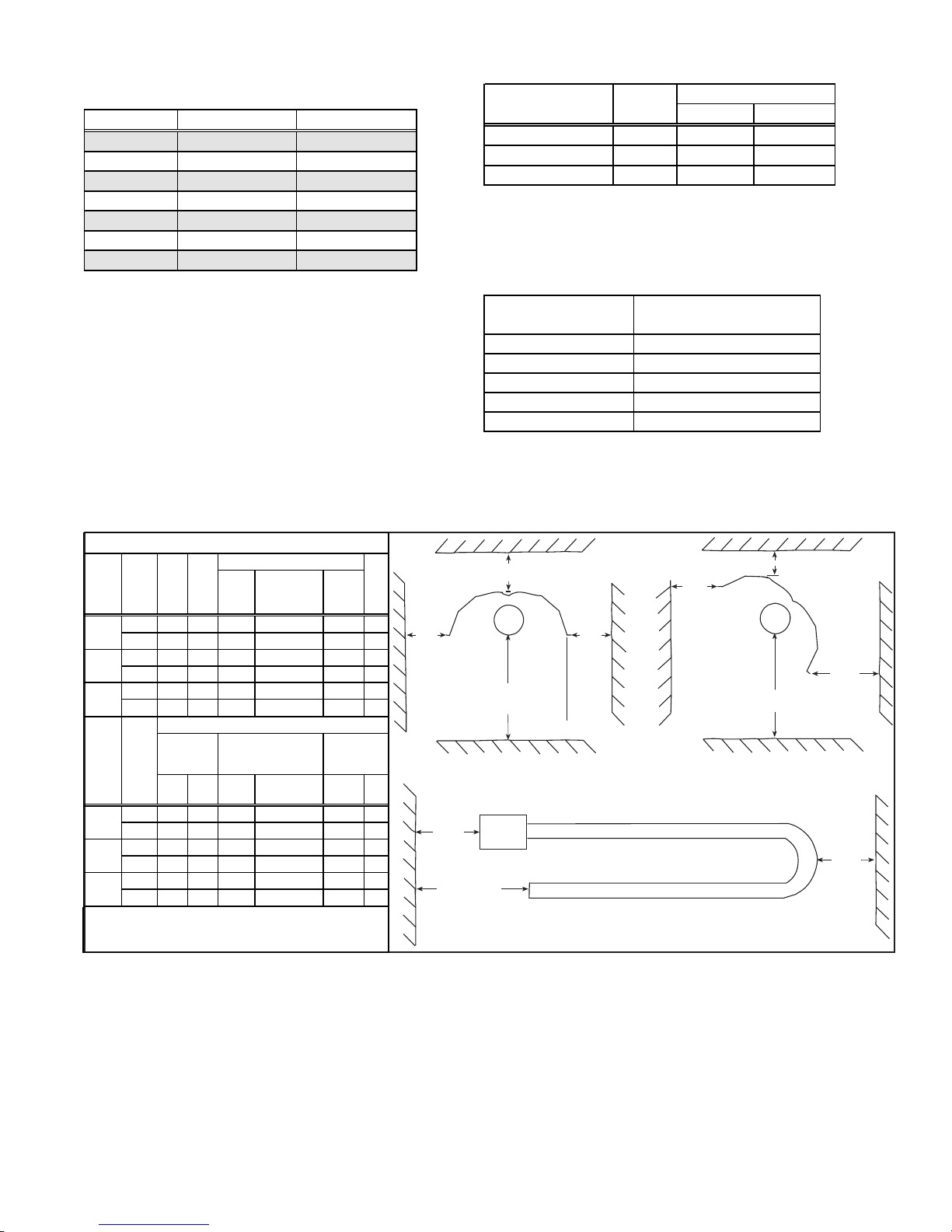
4. Clearances to Combustibles
Required clearances depend on the size of the heater (BTUH input), the position of the reflector, and the addition of an optional side shield on the rear
side of the heater. Refer to illustrations in Figure 1 to def ine clearances.
Clearances to Combustibles
BTUH
Input
(000)
inches
50/75/
100
125/
inches 78
150
175/
inches 84
200
BTUH
Input
(000)
inches
50/75/
100
125/
inches 42 42 66 32 42 12
150
175/
inches 54 54 78 36 54 12
200
* If the heater is not vented to the outside of the building, the
top clearance to combustibles is 18" (457mm).
** Refer to Paragraph 10 for side shield installation.
Below
66 12 24 36 24 6
1676 305 610 914 610 152
mm
1981
mm
mm
2134 305 762 1219 610 152
0-30
Front
30 30 48 18 36 12
762 762 1219 457 914 305
mm
1067 1067 1676 813 1067 305
mm
mm
1372 1372 1981 914 1372 305
Horizontal Clearances
Burner
Top*
End
12
30 48
305
762 1219
12
30 48
With Reflector Positioned
o
Front Rear Front
Rear
Heat
Exch anger
Bend (U o r L )
o
31-45
Exhaust
End
24 6
610 152
24 6
0-30o wit h
Si de Sh i e l d
**
Vent
Rear
Front
of
Reflector
Top of Reflector
Below the Reflector
or Below the Tube
HORIZONTAL REFLECTOR
Burner
End
Exhaust End
Rear
of
Reflector
Optional
Side
Shield
HORIZONTAL CLEARANCES
Figure 1 - Clearance Orientation
Front
of
Reflector
Top of Reflector
Rear
of
Reflector
Below the Tube
REFLECTOR ANGLED (1° TO 45°)
Heat
Exchanger
Bend
Clearance to combustibles is defined as the minimum distance from
the heater to a surface or object that is necessary to ensure that a
surface temperature of 90°F above the surrounding ambient temperature is not exceeded.
The clearances listed in the tables are installation requirements. In
addition, ANSI Z-223-1, Section 6.18, requires that signs be posted
specifying the maximum permissible stacking heights to assure that
the required clearances from the heater to combustibles are maintained in areas where items are stored under the heater.
Refer to Paragraph 1, Special Installations, for specific clearance
requirements for heaters installed in aircraft hangars and public garages.
5. Location and Mounting Height
When selecting the installation location, major factors to consider are (1)
Personal and Property Safety, (2) Personal Comfort, and (3) Heating Efficiency
(1) Safety
The location must meet the Installation Codes listed in Paragraph 1 and any
local codes. These heaters are approved for indoor commercial/industrial
installations only. Do not install these tubular radiant heaters in areas that
contain corrosive or toxic fumes or where elements in the atmosphere could
produce corrosive or toxic fumes in the presence of an open flame. These
heaters do not qualify for explosion-proof installations.
Form RZ-NA-I-TR, Mfg No. 121027 Rev 5,
Page 3
Page 4
5. Location and Mounting
Height (cont'd)
Clearance to combustibles must be observed (See Paragraph 4), including clearances to stock that might be periodically stacked underneath
the heater.
The supporting structure must have a load-carrying capacity of at least
200 lbs.
Do not locate the heater above or too close to electric lines, gas pipes,
emergency sprinkler systems, or any such structures that could be
adversely affected by radiant or convection heat.
Do not locate the heater where it could be damaged by high lifts, cranes,
or any other such equipment.
Since chain suspension is required to allow for expansion and contraction of the tubes, proper positioning near large door openings is important. If the heater is being installed near a large door (ex: garage, loading
dock, aircraft hangar, etc.), position the heater so that it will not "swing"
in the wind. Lateral movement of the tubular system should be limited.
(2) Comfort
Because of the unique heat transfer features of an infrared heater, the
comfort quality of the heat is greatly affected by the location of the
heater. Rays of heat are emitted from the surface of the tubes and
directed by the reflectors. When radiant heat rays reach a surface, those
rays are absorbed, raising the temperature of that "object". Since infrared heat does not heat the air, a comfort advantage is that stratification
does not occur. When the rays are not obstructed from reaching the
floor, the floor and lower level areas maintain a more comfortable
temperature than with convection (warm air) heating equipment.
For optimum comfort when infrared heaters are being used to "heat"
personnel (spot heating), it is recommended that (1) the rays of heat be
directed toward the person(s) from an angle rather than from directly
overhead, and (2) the heater(s) be arranged so that rays are directed
against at least two sides (or front and back) of the person(s). If the
heater must be hung directly overhead, a higher mounting height will
increase the comfort level because the greater distance will decrease the
intensity level of the rays. Another significant factor when locating
the heater in relation to people is that the heat emitted from the
burner/combustion chamber end of the tubular infrared heater is
more intense than the heat emitted from the exhaust end. For this
reason, a U-tube configuration is often best suited for overhead
spot heat applications.
Tubular radiant heaters are engineered to provide comfort-level personal spot and space heating, but each application should be designed
individually to determine the best, quality-comfort locations.
(3) Efficiency
Because of the unique features of radiant heat transfer, selecting the
most efficient location for infrared equipment depends on the "floor"
coverage of the emitted heat rays. Floor coverage distance can be figured as approximately two times the mounting height of the unit. However , comfort level heating depends on the infrared intensity , and intensity levels decrease with higher mounting heights and greater floor
coverage. For more accurate measurement, consult the manufacturer's
flux density tables.
For space heating infrared applications, the location of the units must be
evaluated as part of the heater size selection. Determine the total BTU's
required, the floor coverage required, and the mounting height. From
this information design a heater size and location plan that will provide
the most complete floor coverage without excessive overlapping. In
most cases, perimeter heaters should be located parallel to the wall. The
distance from the wall is determined by whether the reflectors will be
angled or horizontal.
For spot heating applications, the tubular system should be located to
direct the rays toward the area requiring heat. Depending on the installation, this can be done from directly overhead or reflector angled from
the side. U-tube configurations are often best suited to overhead spot
Form RZ-NA-I-TR, Page 4
heating applications. Refer to the recommended minimum mounting heights
below . Use the mounting height, the size of the heater, the heater conf iguration, and the application conditions to determine the most efficient location of the heater.
Recommended Minimum Mounting Height
R e flec tor Size (000 B TUH Input)
Position 50 75 100 125 150 175 200
11 12 13 15 16 17 18
Horizontal
30° Angle
45° Angle
feet
3.4 3.7 4.0 4.6 4.9 5.2 5.5
M
9 101113141516
feet
M 2.7 3.0 3.4 4.0 4.3 4.6 4.9
8 9 10 11 13 14 15
feet
2.4 2.7 3.0 3.4 4.0 4.3 4.6
M
6. Uncrating/Packaging
Check for shipping damage. If any damage is found,document the damage with the shipping agency and immediately contact your Reznor
Dsitributor.
Because of their modular design, these heaters are packaged in sections
and require field assembly . The burner/control box is in one carton, and
the tubes are packaged in one, two or three cartons depending on the
length of the system.
Burner/Control Box Carton - For the convenience of both the stocking
and the non-stocking distributor, the burner/control boxes have two different packaging methods. Read carefully to determine whether or not
the burner/control box requires field conversion before being installed.
(1) Burner/Control Box Packages
Package Contents
TR50 Factory-assembled Size 50,000 BTUH heater
TR75/100 Factory-assembled Size 75,000 BTUH heater
Conversion kit to change to a Size 100,000 BTUH heater
TR125/150 Factory-assembled Size 125,000 BTUH heater
Conversion kit to change to a Size 150,000 BTUH heater
TR175/200 Factory-assembled Size 175,000 BTUH heater
Conversion kit to change to a Size 200,000 BTUH heater
(2) Burner/Control Box Factory Built to a Specific Size - If the burner/
control box carton does not have a label about field conversion, the carton
contains a burner/control box factory-built to a specific size. Check the
rating plate to verify size and type of gas.
Tube Cartons - Tubes are also packaged so that a minimum number of
cartons will cover all lengths of heater systems. This package identification system applies to all heaters, whether shipped from distributor stock
or shipped to order from the factory . Before beginning installation, verify
that the packages at the job site match the length of heater being installed.
Packaging Scheme for Tubes
Pkg P/N Contents
120294 Combustion Chamber Tube; T ail Pipe with T urbulator
120295 Combustion Chamber Tube; Heat Exchanger T ube;
Tail Pipe with Turb ulator
120296 Heat Exchanger Tube; Heat Exchanger T ube with
Turbula tor
Tube Packages (left) Required by Length of System
Length Qty Pkg Qty Pkg
20 ft system requires 1 P/N 120294
30 ft system requires 1 P/N 120295
40 ft system requires 1 P/N 120294 1 P/N 120296
50 ft system requires 1 P/N 120295 1 P/N 120296
60 ft system requires 1 P/N 120294 2 P/N 120296
70 ft system requires 1 P/N 120295 2 P/N 120296
Reflectors, reflector brackets, and hardware packages are included in
Page 5
each carton. (NOTE: Chain for hanging is not included. Use either an Optional Hanger Kit and/or Turnbuckle Kit or field-supplied hardware. See
suspension requirements in Paragraph 7.)
Accessory Cartons -- All field-installed options are shipped in separate cartons.
7. High Altitude Operation
All factory-built Model TR-H units are designed to operate at full input rates at elevations from 2001 to 6000 ft (611-1830M). In addition, Model TRH in Sizes 50 to 175 will operate at full rate at elevations from 2001 to 8000 ft (611-2440M).
High altitude kits are available to convert Size 50, 75, 100, 175, and 200 sea level burner/control boxes for use at high altitudes. Kits are available for
all sizes to convert from one high altitude le vel to another .
If the heater being installed requires high altitude conversion, contact your distributor to obtain the appropriate kit and complete the conversion as part
of the burner/control box preparation in Paragraph 9.
High Altitude Conversion Kits
Gas feet meters
Natural
Propane
*Kits for Size s 125 and 150 may only be used to change a Model TR -H from one high altitude elevation to another.
DO NOT attempt to field convert a sea level Model TR125 or TR150 to high altitude.
**Canadian high altitude installations must choose kits designed for 2001-4000 ft (610-12 19M) elevation.
2001-4000 610-1219 U.S. or Canada** 126440 120880 120882 132664 132667 132670 132673
Gas
4001-6000 1220-1828 U.S. Only 126442 120884 120886 132682 132685 132688 132691
Only
6001-8000 1829-2438 U.S. Only 126444 120888 120890 132700 132703 132706 N/A
2001-4000 610-1219 U.S. or Canada** 126441 120881 120883 132676 13 2679 N/A N/A
Gas
4001-6000 1220-1828 U.S. Only 126443 120885 120887 132694 132697 N/A N/A
Only
6001-8000 1829-2438 U.S. Only 126445 120889 120891 132712 132715 N/A N/A
(full rate operation)
8. Suspension Dimensions and Preparation
Refer to the Suspension Point Dimensions and Installation Configuration Drawings Booklet. This booklet provides suspension
point dimensions, illustrations of permissible configurations for
each size and length of heater, and requirements that must be met to
include an optional 5-ft heat exchanger tube in the system.
From the dimensions on the selected configuration drawing, determine the building suspension points.
WARNING: Install heaters only in the
configurations illustrated or noted in the
configuration booklet (Form RZ 607 in the
Owner's Envelope). Don't install a heater in
a configuration that is not permissible for that
BTUH input capacity or length. See
Paragraph 3 and Hazard Levels on page 2.
Suspension Point Requirements:
1) Supporting structure must have a minimum load-carrying capacity of 200 lbs. (Do not suspend the heater from gas piping
or electrical conduit.)
2) Clearances to combustibles must be observed. See Paragraph
4.
3) Heater must be suspended by hanging chains. Chain, "S" hooks,
and/or turnbuckle length at each suspension point must be a
minimum of 12 inches. All chains suspending tubes must be
plumb. See Figure 2 for dimensions for burner/control box
suspension points.
4) Refer to Paragraph 5 for recommended minimum mounting
heights. The installer is responsible for properly and adequately
fastening the chains to the building and supporting the weight of
the heater. Depending on the type of building construction at the
installation site, either attach the chain support directly to the building or attach and extend a support to the location needed.
SUPERSTRUT® brackets or a comparable metal strut material is
well suited as a support structure that requires numerous suspension points.
Chain must accept a 1/4" "S" hook and have a minimum of 200
lbs working load rating. Use either optional hanging chain kit
(Option CK11) or field-supplied chain.
TR/TR-H TR-H only
50 75 100 125* 150* 175 200
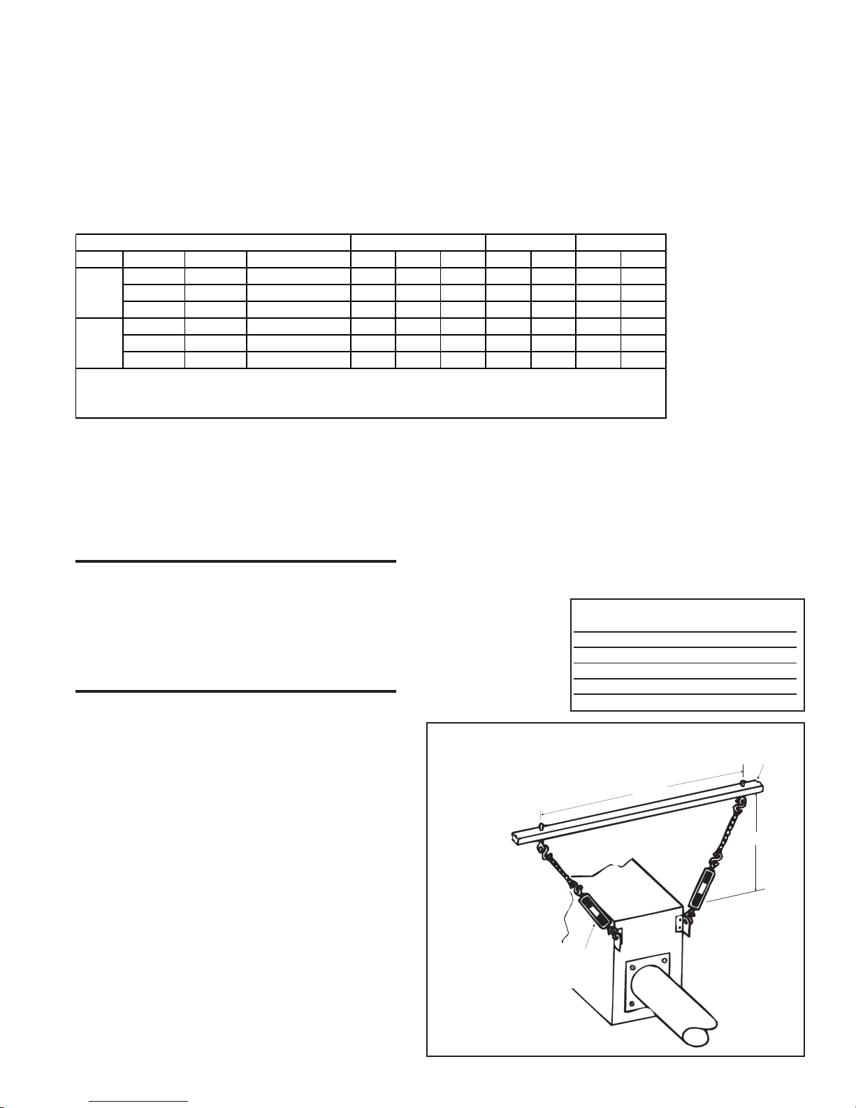
Since the heater must be level, turnbuckles are recommended at the "S"
hook connections on the heater. Turnb uckles must be of steel or malleable
iron. Use either optional turnbuckle kits (Options CK12-20) or field-supplied equivalent.
A minimum length of 12" of chain, "S" hooks and/or turnbuckle is required
at each suspension point.
Chains suspending tubes must be plumb when the heater is installed.
Suspension points required for the burner/control box are illustrated in
Figure 2.
This tubular radiant heater
must be suspended with
chain because the tubes will
expand when heated. The
overall length of a straight
system will expand approximately as shown in
the table.
TR/TR-H
Straight System Expansion Length
70 ft 2-3/4" (70mm)
60 ft 2-3/8" (60mm)
50 ft 2-1/8" (54mm)
40 ft 1-7/8" (48mm)
30 ft 1-1/2" (38mm)
20 ft 1-1/8" (29mm)
Figure 2 - Suspension
Dimensions and Hanging
Arrangement of the
installer or part of the building structure
Burner/Control Box
A + A/4
Optional turnbuckle
Use for convenience
if space permits.
Form RZ-NA-I-TR, Mfg No. 121027 Rev 5,
Structural support added by the
A
At least 12
(305mm) of
chain MUST
BE used for
proper expansion
movement.
Page 5
Page 6
9. Prepare and Install Burner/Control Box and Combustion Chamber
Model Size is stamped
in the upper left hand corner
Combustion Air
Restrictor Plate
10-32 Nuts
Rubber tubing (attaches to
combustion airflow sensor)
Combustion Airflow Sensor
Tube
There are very important steps that must be followed to prepare, suspend, and assemble these tubular radiant heaters. Preparing the heater,
suspension, and field assembly are the responsibility of the installer.
Follow all instructions carefully .
STEP 1) Prepare Burner/Control Box
All burner/control boxes require some field preparation. The type of
preparation depends on how the unit was ordered and where it will be
installed. Determine which of these six situations matches your application and follow the appropriate instructions. The first three are for units
ordered by specific size; the last three are for burner/control box packages that cover two sizes. (Refer to Paragraph 6 for further explanation
on packaging.)
• The unit was ordered as a specific size to be installed at a specific
elevation (sea level or high altitude) and is being installed at
that elevation. Proceed to STEP 2 of these Preparation instructions.
• The unit was ordered as a specific size to be installed at sea level
to 2000 ft and is being installed above 2000 ft (NOTE: Does not
apply to Sizes 125 and 150). Install the high altitude kit selected in
Paragraph 7. Follow the instructions provided with the kit. When the
kit is installed, proceed to STEP 2 of these Preparation Instructions.
• The unit was ordered as a specific size to be installed at an
elevation above 2000 ft and is being installed at a different elevation above 2000 ft. Install the high altitude kit selected in Paragraph
7. Follow the instructions provided with the kit. When the kit is
installed, proceed to STEP 2 of these Preparation Instructions.
• The burner/control box was ordered as a TR75/100, TR125/
150, or TR175/200 and will be installed at sea level to 2000 ft as
a Size 75, 125, or 175. Proceed to STEP 2 of these Preparation
instructions. (The Size Conversion Kit shipped with the burner/control box will not be used.)
• The burner/control box was ordered as a TR75/100 or TR175/
200 and will be installed above 2000 ft elevation as a Size 75, 100,
175, or 200. Install the high altitude kit selected in Paragraph 7.
Follow the instructions provided with the kit. When the kit is installed, proceed to STEP 2 of these Preparation Instructions. (The
Size Conversion Kit shipped with the burner/control box will not be
used.)
• The burner/control box was ordered as a TR75/100, TR125/
150, or TR 175/200 and will be installed at sea level to 2000 ft
elevation as a Size 100, 150, or 200. Follow the instructions below
to install the size conversion kit shipped with the burner/control box.
Instructions to Change the Combustion Air Restrictor Plate and
Burner Orifice to Field Convert a Burner/Control Box from Size
75,000 to 100,000; or from Size 125,000 to 150,000; or from Size
175,000 to 200,000.
Parts Required: Conversion package in the burner/control box includ-
ing a burner orifice, a combustion air restrictor plate, and conversion
labels.
1. Conversion Size Labels (one on the restrictor plate, one or two
loose) -- Fill-in all labels stating that the burner/control box has been
converted to either a Size 100,000, 150,000 or 200,000.
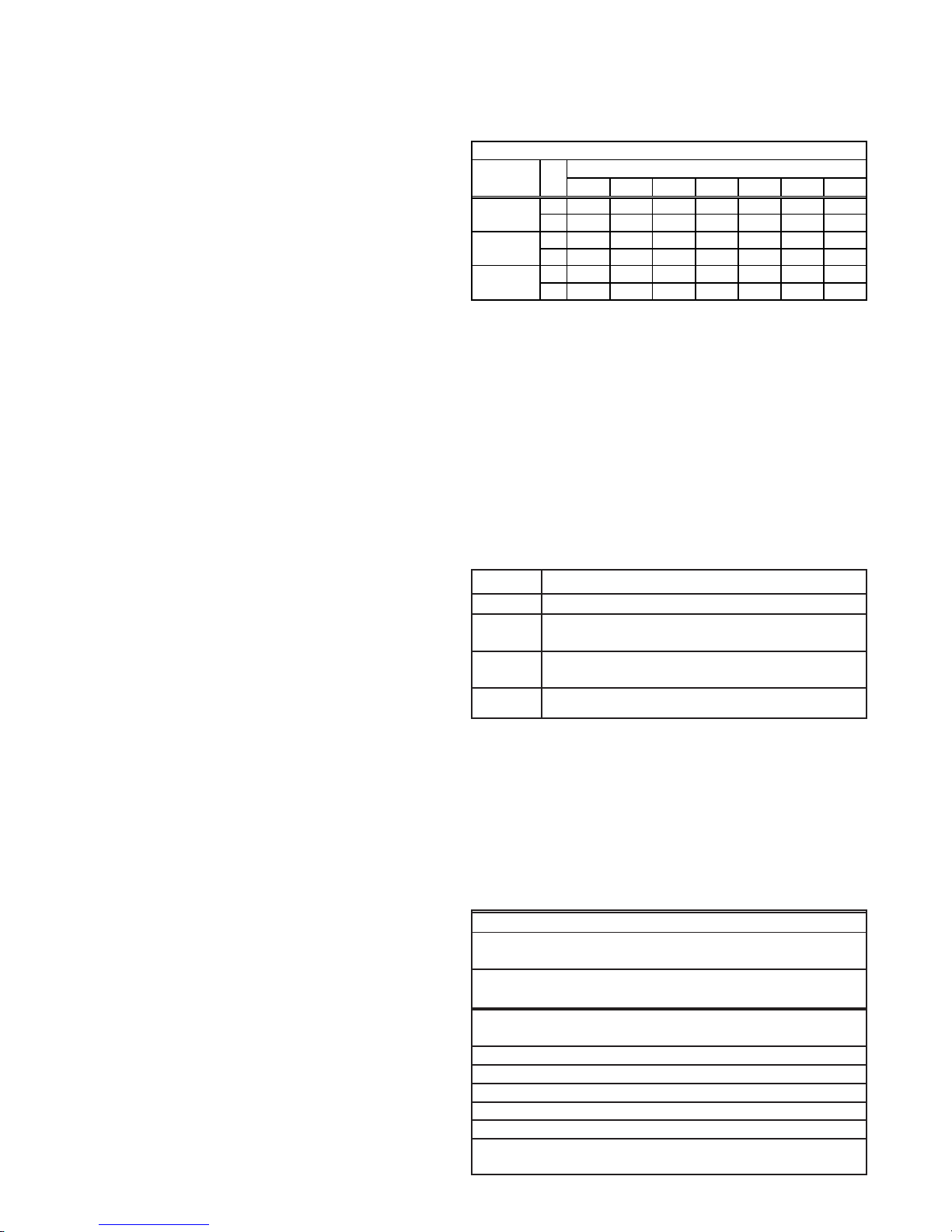
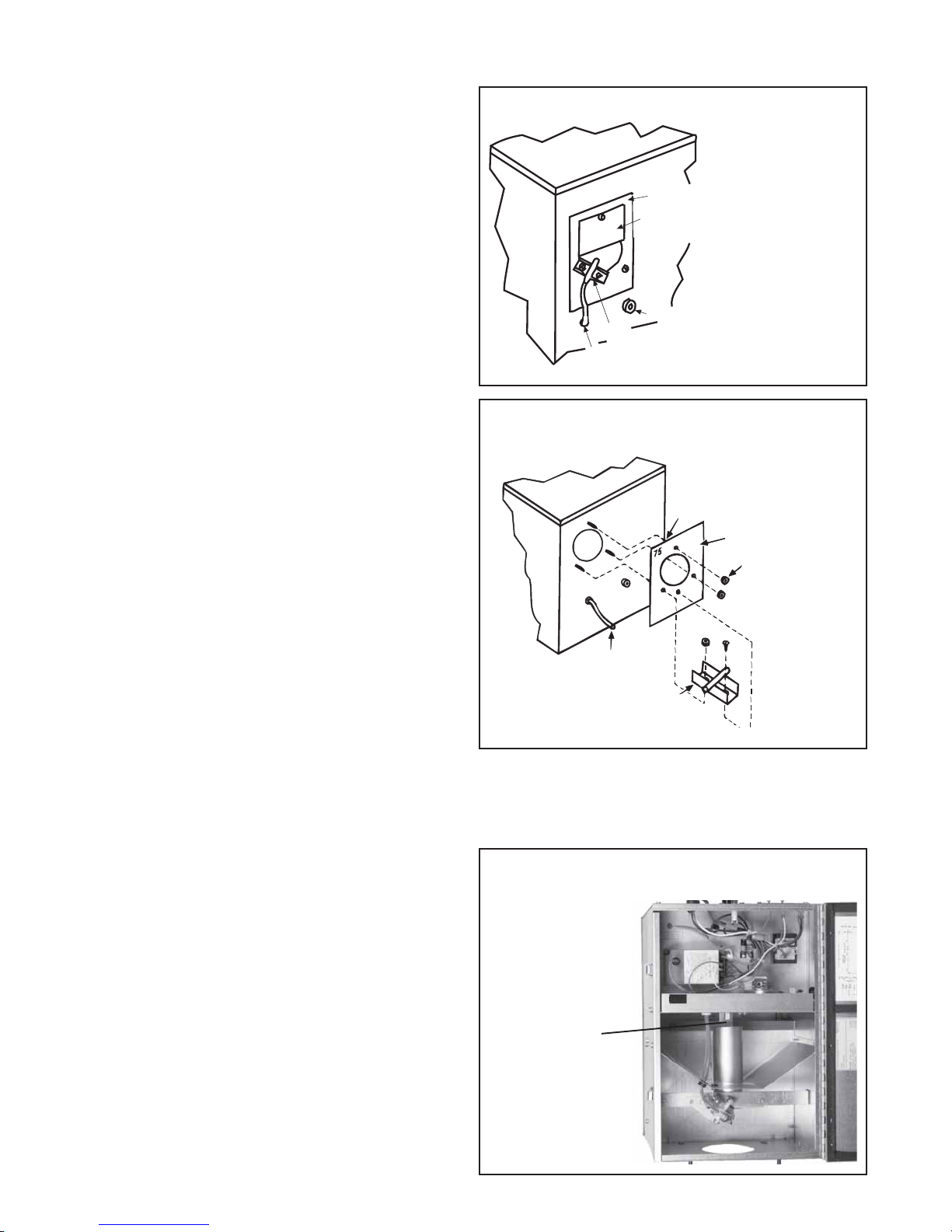
2. Change Air Restrictor Plate -- Refer to Figure 3A and identify the
combustion air inlet on the side of the burner box. Locate the paper
warning label on the factory-installed combustion air restrictor plate.
Attached to the restrictor plate is a combustion air sensor tube and
bracket. See Figure 3B.
Remove the hardware (screws and/or nuts) holding the combustion
air sensor bracket and the restrictor plate. Remove and discard the
factory-installed combustion air restrictor plate. Using the same hardware, attach the combustion air restrictor plate shipped in the parts
bag. Re-attach the combustion air flow sensor bracket.
Form RZ-NA-I-TR, Page 6
Figure 3A - Combustion Air Inlet Side of
Burner/Control Box
Combustion Air Restrictor Plate
IMPORTANT
Tubing to Pressure Switch
Warning label which
must be removed
Static Pressure Port
Combustion Airflow Sensor
Figure 3B - Remove factory-installed air restrictor plate
and replace with the restrictor plate in the parts bag
3. Change Burner Orifice - Open the hinged access panel on the
bottom of the burner/control box. Locate the burner orifice. See Figure 4. Using a 9/16" open-end wrench, remove and discard the factory-installed burner orifice. Install the burner orifice shipped in the
parts bag. Close the bottom panel.
Figure 4 - Burner/Control Box Showing Location of
the Burner Orifice
Burner Orifice
-- Remove with
9/16" open end
wrench
Page 7
4. Adhere label(s) to the burner/control box directly below the rating
plate.
Field size conversion is complete. Continue to STEP 2) Install Com-
bustion Air Inlet Cover.
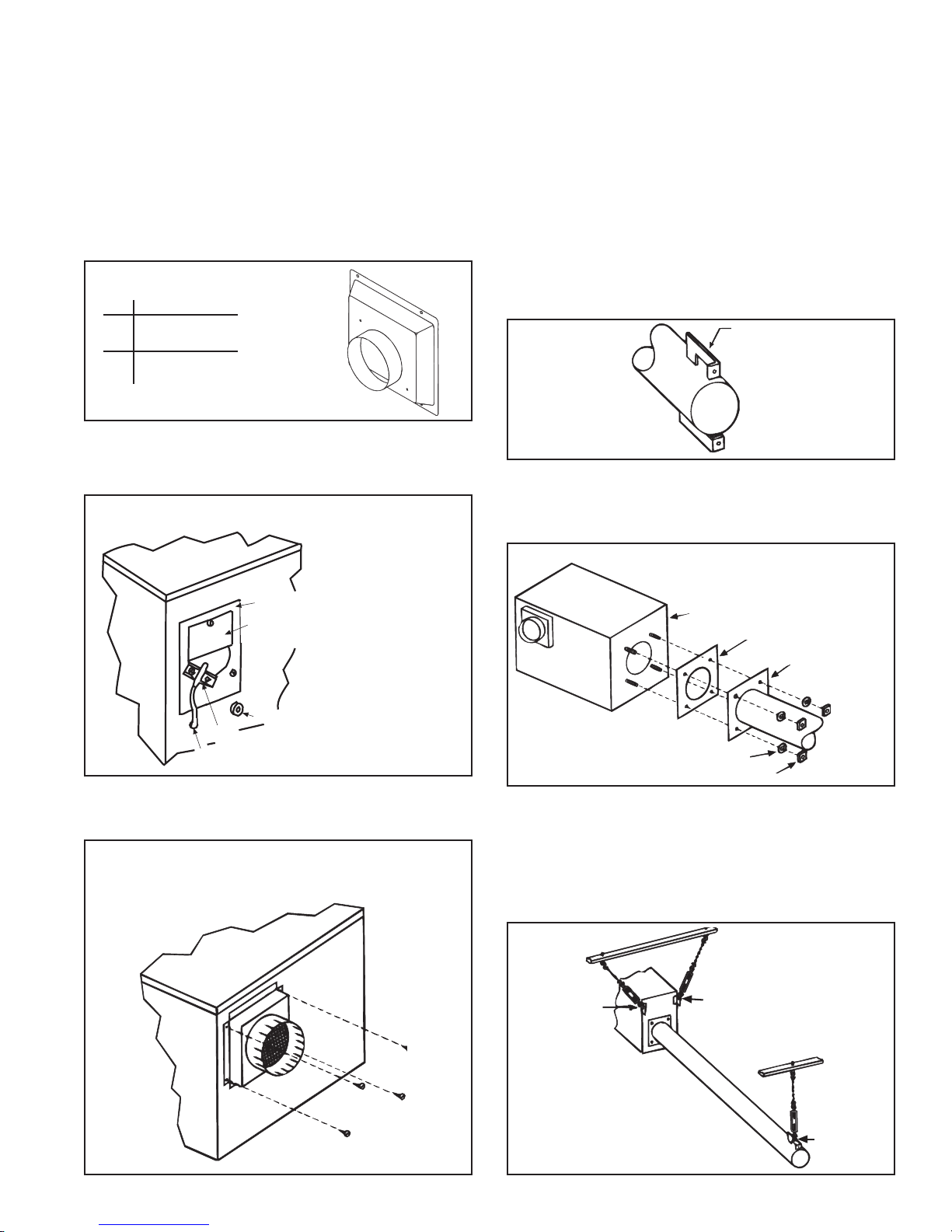
STEP 2 -- Install Combustion Air Inlet Cov er -- Applies to all burner/
control boxes.
From the hardware bag in the burner/control box, remove the instruction
sheet and the parts listed in Figure 5.
Figure 5 - Combustion Air Inlet Cov er
Qty Description
1 Combustion Air
Inlet Cover
4 Screws, #10 x
1/2" long
Instructions:
1. Refer to Figure 6 and identify the combustion air inlet side of the
burner box. If paper warning label is attached, remove.
Figure 6 - Combustion Air Inlet Side of the Burner/
Control Box
STEP 3 -- Assemble and Suspend the Burner/Control Box and
Combustion Chamber Tube
Use these parts (from the hardware bag) to assemble the box and tube.
Qty Description P/N
4 Lockwashers 1333
4 Nuts 1035
1 Gasket 116029
Instructions:
1. Identify the Combustion Chamber Tube -- The tube with the
square flange welded to one end.
2. Attach Combustion Chamber Tube to Burner/Control Box --
Slide the gasket over the bolts on the burner end of the burner/control
box (See Figure 8B). Position the tube so that the hangers (on the end
of the tube) are toward the top and bottom. See Figure 8A.
Slide the flange over the bolts. See Figure 8B.
Figure 8A - End
of Combustion
Chamber T ube
Position hanger
brackets at the top
and bottom
Showing
Position of
Hanger
Brackets
Use the washers and nuts to attach the combustion chamber flange
securely to the burner/control box. (The bolts are pre-welded to the
inside of the box.)
3. Suspend the Combustion Chamber Tube/Burner Box Assem-
Combustion Air Restrictor Plate
Warning label which
RTANT
PO
IM
Tubing to Pressure Switch
2. Position the combustion air inlet cover over the air inlet opening.
Using the four screws in the parts bag, attach the cover to the burner/
control box. See Figure 7.
must be removed
Static Pressure Port
Combustion Airflow Sensor
Figure 7 - Attach Combustion Air Inlet Cover (Fieldattachment of the combustion air inlet cover is
required with either an indoor or outdoor combustion
air supply. )
Figure 8B - Attach the Combustion
Chamber T ube to the Bur ner/Control
Box. Alter nately tighten nuts.
Burner/Control Box
Fiberglass
Gasket
Combustion
Chamber
Lock washers
5/16-16 Nuts (tighten alternately)
bly
Parts needed from the hardware bag: 3 "S" Hooks
Attach the two "S" hooks to the hanger brackets on the burner/control
box. Attach the third to the top hanger bracket on the end of the
combustion chamber tube. Suspend the assembly from the three hanging chains. Refer to Figure 9.
The illustration in Figure 9 includes turnbuckles. Tur nbuckles are
Attach
Attach "S" Hook
"S"
Hook
Figure 9 Suspended Burner/
Control Box with
attached
Combustion
Chamber T ube
Attach
"S"
Hook
Form RZ-NA-I-TR, Mfg No. 121027 Rev 5,
Page 7
Page 8
9. Install Burner/Control Box and Combustion Chamber Tube (cont'd)
3. Suspend the Combustion Chamber Tube/Burner Box Assembly (cont'd)
recommended for use in leveling the heater. If turnbuckles are included in heater suspension, use only optional turnbuckles or field-supplied
turnbuckles of steel or malleable iron.
4. Draw Bolts -- There are two 4-1/2" long bolts left in the hardware bag. These bolts are provided as an aid in connecting tubes. Keep the bolts and
follow the tube connection instructions in Paragraph 10.
10. Install the Heat Exchanger Tube(s), Tail Pipe Tube, and Turbulator
Strip
There are very important steps that must be followed to suspend and assemble these tubular radiant heaters. Preparing the heater, suspension, and filed
assembly are the responsibility of the installer. Follo w all instructions carefully. Throughout the instructions, continued reference to the installation
configuration drawing is required.
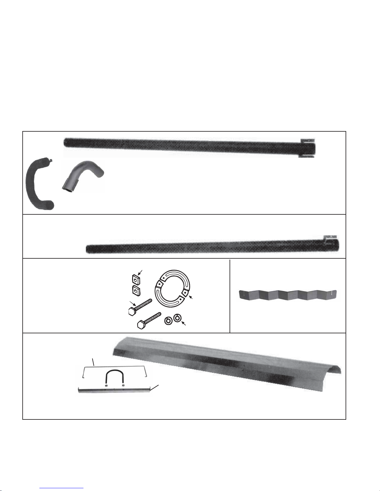
1) Identify the Heat Exchanger and Tail Pipe Tubes and the Parts Packaged with them (Refer to the illustrations in Figures 10A-10E and
the configuration drawing in the configuration booklet):
Expanded
End
10' Straight Tube
5' Straight Tube
T w o Hanger
Brackets
"U"
"L" T ube
Tube
"U" and "L" tube packages include
field-assembled reflectors
Figure 10B - Tail Pipe Tube (10')
Expanded
End
A parts bag is supplied with each
heater tube and tail pipe. The bag
contains hardware needed to
connect two tubes, an "S" hook,
and an instruction sheet.
Figure 10C Connection
Hardware Parts Bag,
P/N 116017
Figure 10E Reflector,
Reflector
Retainer , and
Retainer
Reflector
Bracket and
Hardware (Ubolt and nuts)
Bolts
Square
Nuts
Figure 10A - Heat Exchanger
T ubes (Straight, "U", and "L")
Swedged End with One
Hanger Bracket
Figure 10D - One Section of the
Field-Installed T urbulator Strip
Clamping
Rings
Lock
W ashers
Reflector
Bracket
One 10' reflector and two reflector retainers and two brackets with hardware per 10' straight tube.
Optional 5' heat exchanger tube includes a 5' reflector and two sets of retainers and brackets with hardware.
Follow installation instructions in Paragraph 11.
2) Suspend and Connect the Heat Exchanger Tubes and Tail Pipe
-- Follow the Configuration Drawing Layout
Connect each tube as it is suspended. If your configuration requires a
turbulator strip before a "U" or "L" tube, insert the turbulator strip before
the "U" or "L" tube is connected. Follow the instructions in Step No. 3)
on pages 9-11, and install two sections of turbulator strip. (This will only
Form RZ-NA-I-TR, Page 8
occur when installing a 40' to 70' system in a configuration where a "U"
or "L" tube connects directly to the tail pipe.)
Suspending Straight (5-ft or 10-ft) Heat Exchanger Tubes and
"U" T ubes - Attach an "S" hook to the hanger bracket and suspend the
tube from the next hanging chain. Slide the expanded end over the previous tube and make the connection.
Page 9

Installing "L" Heat Exchanger T ubes - "L" tubes do not require a suspension point. When the configuration requires an "L" tube, slide the expanded
end over the previous tube and make the connection.
Suspending the T ail Pipe - Attach an "S" hook to the hanger bracket and suspend the tube from the last hanging chain. Slide the expanded end over
the previous tube and make the connection.
Connecting the Tubes - Using the hardware in the bag packaged with each tube, follow the steps in Figure 11 to connect the tubes.
1) Connection Hardware
Square
Nuts
Bolts
2) Step 1
Combustion
products flow
direction
Figure 11 - Steps for Connecting Tubes
Lock
Washers
Suspended T ube
Section
T ube Section to be
added (suspend at
opposite end)
Clamping
Rings
3) Step 2
4) Connected Tubes
Tighten
bolts
securely.
IMPORT ANT: If tubes do not slide together easily, f ollow
Installation Tip below .
Be certain inner tube mates to
bottom of expansion in outer tube.
Installation Tip: If tubes are difficult to slide tubes together , use the two 4-1/2" long bolts from the b urner/contr ol box
parts bag to draw the tubes together . F ollow illustrated Step 2 (Figure 11, page 9), using the 4-1/2" bolts. Alternate
tightening the upper and lower bolts. When the tubes are in position, remove one of the long bolts, replace with a
connecting bolt, and secure. Repeat, replacing the other bolt. Re-use the 4-1/2" bolts as needed.
3) Install the Turbulator Strip -- Locate turbulator strip sections.
System L ength 20 30 40 50 60 70
Tube Package(s) E F E G F G E G G F G G
Full Size Turbulator
Section, 37-1/8" long
Sma ll Turbulator
Section, 26" long
333232322322
101000100000
Figure 12A - Turbulator Strip Section
Figure 12B - Interlock Sections as Turbulator Strip is
Instructions: Install a turbulator strip in a tube only after
that tube has been suspended and connected to the previous
tube. Refer to Figures 12A and 12B. Install the turbulator
strip by sliding a section into the tube, connecting the next
section, and sliding the connected sections on into the tube(s).
Follow the selected configuration drawing in the configuration booklet and the instructions in the chart on page 11.
Installed
Turbulators interlocked ready
for insertion into heat exchanger
Slide Together
Turbulators
tubes.
Form RZ-NA-I-TR, Mfg No. 121027 Rev 5,
Page 9
Page 10

10. Installing the System (cont'd)
g
Length
of
Strai
Tubes
20 ft
25 ft
30 ft
BTUH
Size
ht
(000)
50
75
50
75
50
75 0 - 8000 ft*
Ele vation
0 - 8000 ft*
0 - 8000 ft*
Configuration
(Must be illustrated in t he
Suspension Dimension and
Configuration Booklet.)
St ra igh t
"U" or "L"
All
All
Turbulator Sections
In Tube
Packages
Qty Size** Qty Size**
3 37-1/8"
1 26"
3 37-1/8"
1 26"
3 37-1/8"
3 37-1/8"
Configuration
3 37-1/8"
1 26"
3 37-1/8"
3 37-1/8"
3 37-1/8"
100
35 ft
40 ft
45 ft
50 ft
75
0 - 8000 ft*
100
75
0 - 8000 ft*
100
125
100
0 - 8000 ft*
125
100
125
0 - 8000 ft*
150
175
0 - 2000 ft
200
175 2001-8000 ft*
All
Str aight heat exchanger tube adjacent
to the tail pipe
"U" or "L" tube adjacent to the tail
pipe
(See Figure 12D)
Str aight heat exchanger tube adjacent
to the tail pipe
"U" or "L" tube adjacent to t he tail
pipe
(See Figure 12D)
Str aight heat exchanger tube adjacent
to the tail pipe
"U" or "L" tube adjacent to t he tail
pipe
(See Figure 12D)
All 5 37-1/8"
(See Figure 12C)
(Se e Figure 12C)
(See Figure 12C)
3 37-1/8"
5 37-1/8"
1 26"
5 37-1/8"
1 26" 3 long sections after tail
5 37-1/8"
1 26"
5 37-1/8"
1 26" 3 long sections after tail
5 37-1/8"
5 37-1/8"
3 37-1/8"
5 37-1/8"
5 37-1/8"
5 37-1/8"
5 37-1/8"
5 37-1/8"
5 37-1/8"
3 37-1/8"
200 2001-6000 ft*
55 ft
150 0 - 8000 ft*
175
0 - 2000 ft
200
175 2001-8000 ft*
Str aight heat exchanger tube adjacent
to the tail pipe
"U" or "L" tube adjacent to t he tail
pipe
(See Figure 12D)
All 5 37-1/8"
(See Figure 12C)
5 37-1/8"
5 37-1/8"
5 37-1/8"
5 37-1/8"
3 37-1/8"
200 2001-6000 ft*
60
150 0 - 8000 ft*
ft
175
200
175 2001-8000 ft*
0 - 2000 ft
Str aight heat exchanger tube adjacent
to the tail pipe
"U" or "L" tube adjacent to the tail
pipe
(See Figure 12D)
All 7 37-1/8"
(See Figure 12C)
7 37-1/8"
7 37-1/8"
5 37-1/8"
5 37-1/8"
3 37-1/8"
200 2001-6000 ft*
65 o r
70 ft
175
0 - 2000 ft
200
175 2001-8000 ft*
Str aight heat exchanger tube adjacent
to the tail pipe
"U" or "L" tube adjacent to the tail
pipe
(See Figure 12D)
All 7 37-1/8"
(Se e Figure 12C)
7 37-1/8"
7 37-1/8"
5 37-1/8"
5 37-1/8"
3 37-1/8"
200 2001-6000 ft*
* To install a heater above 2000 ft elevation, that heater must either be factory-built for the required elevation or field-conver ted to that
elevation. Check the rating plate or field conversion label for allowable altitude.
** Metric equivalent: 37-1/8" is 943mm; 26" is 660mm
Form RZ-NA-I-TR, Page 10
(Some sections may not be used; follow instr uctions.)
Used
in the
Quantity, Type and
WHEN to Instal l
All 4 sections after tail
pipe is connected
3 long sections after tail
pipe is connected
All 3 sections after tail
pipe is connected
All 3 sections after tail
pipe is connected
All 3 sections after tail
pipe is connected
5 long sections after tail
pipe is connected
2 long sections before
"U" or "L" is con nected
pipe is connected
5 long sections after tail
pipe is connected
2 long sections before
"U" or "L" is con nected
pipe is connected
All 5 sections after tail
pipe is connected
2 sect ions before "U" Int o end of st raight
or "L" is connected before "U" or "L"
3 sections after t ail pipe
is connected
3 sections after t ail pipe
is connected
All 5 sections after tail
pipe is connected
2 sections before "U"
or "L" is connected
3 sections after t ail pipe
is connected
3 sections after t ail pipe
is connected
5 sections after tail pipe
is connected
2 sect ions before "U" Int o end of st raight
or "L" is connected before "U" or "L"
3 sections after t ail pipe
is connected
3 sections after t ail pipe
is connected
5 sections after tail pipe
is connected
2 sect ions before "U" Int o end of st raight
or "L" is connected before "U" or "L"
3 sections after t ail pipe
is connected
3 sections after t ail pipe
is connected
Into exhaust end of tail
pipe
Into exhaust end of tail
pipe
Into exhaust end of tail
pipe
Into exhaust end of tail
pipe
Into exhaust end of tail
pipe
Into exhaust end of tail
pipe
Into end of straight
tube before "U" or "L"
Into exhaust end of tail
pipe
Into exhaust end of tail
pipe
Into end of straight
tube before "U" or "L"
Into exhaust end of tail
pipe
Into exhaust end of tail
pipe
Into exhaust end of tail
pipe
Into exhaust end of tail
pipe
Into exhaust end of tail
pipe
Into end of straight
tube before "U" or "L"
Into exhaust end of tail
pipe
Into exhaust end of tail
pipe
Into exhaust end of tail
pipe
Into exhaust end of tail
pipe
Into exhaust end of tail
pipe
Into exhaust end of tail
pipe
Into exhaust end of tail
pipe
Into exhaust end of tail
pipe
WHERE to Inst all
Page 11

Figure 12C - Examples of Configurations with the Tail Pipe Adjacent to a Straight Heat Exchanger Tube
Tail Pipe
Tube
Tail Pipe
Straight
Tube
Straight
Straight
Tube
Figure 12D - Examples of Configurations that require more than three turbulator
strips and have the tail pipe adjacent to an "L" or "U" heat exchanger tube
Tail Pipe
LTube
Straight
Tube
Straight
Tube
Tail Pipe
U
Tube
Tail Pipe
T o install turb ulator:
1) Attach the tail pipe to the straight
pipe.
2) Insert a turbulator section into the
tail pipe.
3) Interlock turbulator sections as
they are inserted (See Figure
12B).
4) Continue until all required sections are in place.
T o install turb ulator:
1) Before attaching the "U" or "L" tube,
insert two interlocked turbulator sections (See Figure 12B) into the last
straight tube.
2) Attach the "U" or "L" heat exchanger
tube to the straight tube.
3) Attach the tail pipe to the "U" or "L"
tube.
4) Insert three interlocked turbulator
sections into the tail pipe.
Su mmary of Number of Sections Required to "Build" Turbulator Strip
(NOTE : There may be sections in the packages that ar e not used.)
Elevation of
Installation (ft)
0 - 8000 50-75-100 30 ft 3
0 - 2000 175-200 50 ft 5
2001-8000 175-200* 3
0 - 8000 150 55, 60 ft 5
0 - 2000 175-200 55, 60, 5
2001-8000 175-200* 65, 70 ft 3
*Size 200 - Maximum elevation is 6000 feet.
BTUH Sizes
(000)
50-75 20 ft "U" or "L" 3
75-100 35 ft Straight, 3
75-100-125 40 ft "U", 5
100-125 45 ft and 5
100-125-150 "L" 5
4) Level the System and Close "S" Hooks
Tubes must be lev el. Use a spirit level and adjust the turnb uckles or chain links. Close all "S" hooks being careful not to change the chain length. When
the system is level, re-check to be sure that all bolts connecting the tubes are tightened securely .
Straight systems should be straight; systems with "L" tubes should be at right angles; and "U" shaped systems should be parallel.
Length
(Straight)
20 ft Straight 4 (3 long, 1 short)
25 ft 3
Configuration
No. of Sections used in
Turbulator Strip
Form RZ-NA-I-TR, Mfg No. 121027 Rev 5,
Page 11
Page 12

11. Install Reflectors (including Standard Reflectors, Optional Side
Shield and Optional Reflector Gap and End Covers)
WARNING: Do not operate heater without reflectors. See Hazard Intensity Levels, page 2.
Packaged with each straight tube is a reflector, two reflector brackets with hardware, and two reflector retainers (Refer to Figure 10E on page 7). Follow
the instructions to install a reflector on all straight tubes.
NOTE: If the installation includes an optional side shield, the side shield package (Options CD13-20) includes two additional reflector brackets and
retainers for each 10-ft tube. All four br ackets must be attached to each 10-ft tube before installing the reflector.
Reflector Installation Instructions
1. From the table, determine the
number of brackets (and retainers) required per tube and
select the appropriate illustration (Figure 13A or 13B).
2. Install Reflector Brackets
Tube
Length
Side
Shield
Number of
Brackets
Refer to
Figure
10-ft Without 2 13A
10-ft With 4 13B
5-ft Without 2 13A
5-ft With 2 13B
(See Figure 13A or 13B)
a) Slide the U-bolt over the tube at the determined location.
b) Position the reflector bracket as illustrated (end flanges extend-
ing upward) and slide the bracket over the bolt ends. Adjust the
bracket to the desired reflector angle (0-45
o
). Use the nuts to
attach the reflector bracket to the U-bolt.
c) Repeat the procedure to install all required brackets.
Figure 13A - Locations for Reflector Brackets for
Systems without an Optional Side Shield
10-ft Heat Exchanger Tube
U-Bolt
Optional 5-ft Heat Exchanger Tube
12
(305mm)
Reflector Bracket
6 feet (1.8M)
36 (914mm)
12
(305mm)
approximate
3. Install the Reflector, Optional Side Shield, and Reflector
Retainers (Refer to Figure 15)
a) All Installations -- Nestle the reflector inside the flanged edges
of the reflector brackets.
b) Installations with Optional
Side Shield -- The side shield is
modular with two sections per
10-ft tube. When side shields are
included in the installation, drill a
Figure 14 - With
optional side shield,
insert a screw in each
tube joint to prevent
tubes from turning
9/64" hole in each tube joint and
insert the screw provided (See
Figure 14). Hang the side shield
sections over the ends of the reflector brackets (Maximum angle
with side shield is 30°). IMPOR-
TANT: Install side shield on
one side of the system only.
U-bolt
1/2" (13mm)
Reflector
Drill
9/64"
hole
Reflector
Retainer
Optional
Side
Shield
Reflector
Bracket
Figure 15 - Install Reflector ,
Side Shield (Optional), and
Reflector Retainers
Form RZ-NA-I-TR, Page 12
Figure 13B - Locations for Reflector Brackets for Systems
with an Optional Side Shield
10-ft Heat Exchanger Tube
2 ft
(610mm)
13
(330mm)
Optional
5-ft Heat
Exchanger
Tube
32-3/4
(832mm)
c) All Installations -- Position a wire retainer over the reflector and hook the
ends through the holes in the reflector brackets. Install a retainer at each
reflector bracket.
d) All Installations -- Repeat the instructions to install reflectors on each
straight section of tube in the system. Do not operate the heater without all
reflectors installed.
4. Install Optional Reflector Gap Covers -- The optional gap covers are
designed to provide the infrared tubular
system with a continuous reflector while
still allowing for system expansion. If
optional reflector gap covers are included
in the installation, follow the illustrated
instructions included in the option package. Reflectors on systems with gap covers cannot be rotated.
5. Install Optional Reflector End Cover -
- The optional end covers are designed to
"close" the vertical space on both the combustion chamber end and the tail pipe end
of the reflector length. The end covers may
only be installed on units that have optional reflector gap covers. Follow the illustrated instructions included in the option package.
6. Rotating Reflectors -- Reflectors on straight systems without reflector gap
covers or a side shield may be angled up to 45° by rotating the U-bolt and
reflector bracket.
Reflectors with gap covers cannot be rotated.
Reflectors on straight systems with a side shield may be angled up to 30°.
The side shield must hang vertically .
13
(330mm)
24-1/2
(622mm)
(832mm)
32-3/4
32-3/4
(832mm)
Figure 16A Optional
Reflector Gap
Cover
Figure
16B Optional
Reflector
End
Covers
Page 13

If the system includes a "U" or "L" heat exchanger tube, the reflectors on
either adjacent side of the "U" or "L" reflector cannot be rotated and must
remain horizontal. All reflectors in a section or leg of the tubular system
should be at the same angle.
12. Venting
V enting must be in accordance with the National Fuel Gas Code Z223.1 (NFP A
54) or CAN/CGA B149.1 and B149.2, Installation Code for Gas Burning
Appliances and Equipment, and all local codes.
ANSI standard applicable to this heater does not require venting categorization; if such a requirement existed, this heater would be in Category III. (Category III appliances have a positive-pressure vent requiring a gastight sealed
vent system.) These tubular infrared heaters have been designed to operate
safely and efficiently with vent pipe lengths sho wn in the Vent Length T able.
Vent systems may either be vertical or horizontal. The type of vent required
depends on the size of heater and the vent run configuration.
Type of Vent Required by Vent Category
Model Sizes 50-125 150-200
- with a Horizontal Vent Run Category III Category III
- with a Vent Run that is at least one-half Category I
vertical (using equivalent lengths from the or Category III
Vent Length Table below) Category III
- with a Dual Vent Adapter (Option CC5) Category III Category III
V ent terminal end may be either single-wall pipe or double-wall pipe . A vent
terminal cap is required. Install a vent cap supplied as Option CC1 or a fullycomparable, field-supplied vent terminal cap such as a T ype L Breidert Air-xhauster®. (T ype L Air-x-hauster® is a trademark of The G. C. Breidert Company.) Dual v enting of two units is permissible when using an Optional Dual
Vent Kit (Option CC5).
Comply with the specific requirements and instructions in the following paragraphs.
Specific V ent Requirements
1. Vent Pipe Length - The vent lengths sho wn in the V ent T able are based on
(1) the maximum permissible resistance to flow at which each model size will
operate and (2) the potential for continuous condensing. Condensing in the
vent pipe should not occur after equilibrium has been reached when the surrounding ambient temperature is 60°F unless otherwise noted (See Requirement No. 6, Condensation).
Do not exceed maximum vent length. Minimum vent length is 5 feet.
Use equivalents listed when calculating for elbows and optional dual vent
adapter (Option CC5).
Ven t Length T able for Tubula r Infra red H ea ters
Vent Length Equivalent Length for
Straight
Tube
Length
(ft)
Input Size (000)
50 20, 25, 30 4 20 5 6.1 1.5 3 0.9 1-1/2 0.5 3 0.9
20, 25 4 45 5 13.7 1.5 6 1.8 3 0.9 6 1.8
75 30, 35 4 35 5 10.7 1.5 5 1.5 2-1/2 0.8 5 1.5
40 4 20 5 6.1 1.5 3 0.9 1-1/2 0.5 3 0.9
30, 35 4 45 5 13.7 1.5 6 1.8 3 0.9 6 1.8
100 40, 45 4 35 5 10.7 1.5 5 1.5 2-1/2 0.8 5 1.5
50 4 20 5 6.1 1.5 3 0.9 1-1/2 0.5 3 0.9
125 40, 45, 50 4 60 5 18.3 1.5 12 3.7 6 1.8 12 3.7
150 50, 55, 60 4 60 5 18.3 1.5 12 3.7 6 1.8 12 3.7
50, 55, 60,
175
65, 70
50, 55, 60,
200
65, 70
Must be deducted from the total vent length of
*
Vent Diameter
feet M
(inches)
Max Min Max Min ft M ft M ft M
4 60 5 18.3 1.5 12 3.7 6 1.8 12 3.7
4 60 5 18.3 1.5 12 3.7 6 1.8 12 3.7
Elbow
each
90°
heater.
45°
Elbow
Dual
Vent
Adapter
Box
*
2. Vent Pipe Type - Use only 4-inch diameter vent pipe.
If the type of vent required is Category III (refer to table
above), use either a vent pipe approved for a Category III heater or
appropriately sealed 26-gauge galvanized steel or equivalent singlewall pipe.
If the type of vent required is Category I (refer to table above),
unsealed 26-gauge galvanized steel or equivalent single-wall pipe
or double-wall (T ype B) vent pipe may be used.
3. Vent Pipe Joints - Vent system joints depend on the vent category and the type of pipe being used.
If installed as a Category III appliance and using single-wall
vent pipe, join pipes with at least two non-corrosive screws per
vent pipe joint and seal all joints to prevent leakage of flue gases
into the building. For sealing joints, the use of Alumin um or
TEFLON® (trademark of DuPont Corporation) tape suitable for
550°F is recommended (required in California). Vent tape of this
type is available from the heater manufacturer as P/N 98266.
If installed as a Category III appliance and using vent pipe
specifically approved for Category III vent systems, follow
the pipe manufacturer's instructions for proper sealing.
If installed as a Category I appliance (allowed only for Sizes
50-125 when at least half of the total equivalent length of the
vent system is vertical), use at least two non-corrosive screws per
vent pipe joint on single-wall pipe or follow the pipe manufacturer's
instructions for joining double-wall pipe.
Attach Vent Pipe to Heater - The last heat exchanger section
4.
(tail pipe) is designed to permit direct attachment of a vent pipe,
either straight or elbow .
Attach metal vent pipe using three non-corrosive screws spaced
equal distance apart. See Figures 17A and 17B.
Non-corrosive sheetmetal
screws spaced approximately
120° apart
Suspended
Tail Pipe
Figure 17A Attach Metal
V ent Pipe to
Tail Pipe
Single wall
elbow or
Single wall straight pipe section
T ape joint with high temperatur e
aluminum tape or seal with high
temperature silicone rubber sealant.
Figure 17B - Seal
T ail Pipe and Vent
Pipe Joint
5. Vent System Support - Vent pipe support is especially impor-
tant with the tubular infrared system because of the added stress
which may be caused by expansion and contraction of the overall
system. Support lateral runs a minimum of every six feet using
non-combustible material, such as steel strap or chain. Do not rely
on the heater for support of either horizontal or vertical vent pipe.
Form RZ-NA-I-TR, Mfg No. 121027 Rev 5,
Page 13
Page 14

g
e
.
11. Venting (cont'd)
6. Condensation - If single-wall vent pipe is exposed to cold air or run
through unheated areas, it must be insulated. Where extreme conditions
are anticipated, install a means of condensate disposal.
7.
Vent Terminal and Vent Cap - The vent system must be terminated
with the type of vent cap approved for use with this heater. The vent
terminal and vent cap must be the same diameter as the vent run. Use
either an optional (Option CC1) vent cap or equiv alent such as a T ype L
Breidert Air-x-hauster®. (Type L Air -x-hauster® is a trademark of The G.
C. Breidert Company.) A different style vent cap could cause nuisance
problems and/or unsafe conditions.
See the illustrations in Figures 18 and 19 for requirements of both vertical and horizontal vent termination. Using either single or double wall
vent terminals is illustrated. Many local codes require the use of doublewall (T ype B) vent for the portion of vent pipe (terminal) on the outside
of the building.
If double-wall pipe is used in the vent terminal, follow the instructions
below to attach the vent cap and to connect the double-wall pipe to the
single-wall vent system.
INSTRUCTIONS FOR DOUBLE WALL PIPE INSTALLATION: Material Required: Double wall (Type B) Vent Pipe (Note:
Use only one piece of double wall vent pipe.); a thimble designed for
double wall pipe (if construction is combustible); six 3/4" long
sheetmetal screws; the vent cap; and a tube of silicone sealant.
Instructions to attach VENT CAP to DOUBLE WALL (Type B)
VENT TERMINAL
Look for the "flow" arrow on the vent pipe. Attach the vent ca p to the
"exhaust" end of the double wall pipe.
1) Slide the vent cap inside the pipe.
2) Drill a hole through the pipe and the vent cap. (Hole should be
slightly smaller than the sheet metal screw being used.) Using a 3/4"
long sheet metal screw , attach the cap to the pipe.
3) Repeat Step 2) drilling and inserting two additional screws evenly
spaced (120° apart) around the pipe.
Instructions to connect the SINGLE WALL VENT system to a
DOUBLE WALL (Type B) VENT TERMINAL:
1) Slide the single wall pipe inside the inner wall of the double-wall
terminal pipe.
2) Drill a hole through both walls of the double wall pipe and the single
wall pipe. (Hole should be slightly smaller than the sheet metal screws
being used .) Using a 3/4" long sheet metal screw , attach the two pieces
of pipe. Do not overtighten.
3) Repeat Step 2) drilling and inserting two additional screws evenly
spaced (120° apart) around the pipe.
4) T o seal the annular opening (the gap between the single and double
wall pipe), run a large bead of silicone sealant in the opening. The bead
of sealant must be large enough to seal the opening, but it is not
necessary to fill the full volume of the annular area.
Figure 18A - Vertical Vent Terminal Arrangements (drawings are not proportional; read all information)
SINGLE WALL - Single wall vent run and single wall
terminal end
6 ft
(1829mm)
minimum
Roof Flashing
Roof pitched
Parapet or adjoining building
from 0 to 45°
Vertical flue extension must
be 6 (152mm) higher than
anticipated snow depth but no
less than 24 (610mm) above
the roof. Vertical pipe extension
must be insulated.
An approved clearance
thimble for single-wall
vent pipe is required when
the flue piepe extends
h combustible maerial.
throu
DOUBLE WALL - Single wall vent run and double
wall terminal end
6 ft
(1829mm)
minimum
Roof Flashing
6 (152mm)
Parapet or adjoining building
minimum
Follow the instructions above to join double wall and
single wall pipe and to attach a vent cap to double wall pipe.
Vertical flue extension
to be 6 (152mm) higher than
anticipated snow depth but no
less than 24 (610mm) above
the roof. Vertical pipe extension
must be insulated.
Roof pitched
from 0 to 45°
Clearance to be as specified on
Type B (double wall) vent pipe
Figure 18B - Vertical Vent Terminal/Air Intake Arrangements (dra wings are not proportional; read all information)
SINGLE WALL - Single wall vent run; single wall
terminal end; and single wall fresh air intake
6 ft
(1829mm)
minimum
Vertical flue extension
to be 6 (152mm)
higher than anticipated snow depth
but no less than 24
(610mm) above the roof.
Parapet or adjoining building
Vertical pipe extension
must be insulated.
Roof pitched
from 0 to 45°
An approved clearance
thimble for single wall
vent pipe is required
when the flue pipe extends
through combustible
mat
rial
Form RZ-NA-I-TR, Page 14
3 ft (914mm)
minimum
Roof Flashing
If the fresh air intake is
within 10 feet (3M) of the
flue extension, the flue
extension must be at least
12 (305mm) higher than
the fresh air intake.
Fresh air intake must
be 6 (152mm)
higher than anticipated snow depth.
DOUBLE WALL - Single wall vent run; double wall
terminal end; and single wall fresh air intake
6 ft
(1829mm)
minimum
Vertical flue extension
to be 6 (152mm)
higher than anticipated
snow depth but no less
Parapet or adjoining building
than 24 (610mm) above
the roof. Vertical pipe
extension must be
insulated.
Roof pitched
from 0 to 45°
6 (152mm)
minimum
Follow the instructions above to join double wall and single
wall pipe and to attach a vent cap to double wall pipe.
3 ft (914mm)
minimum
Roof Flashing
Clearance to be
as specified on
Type B
(double wall)
vent pipe
If the fresh air intake is
within 10 feet (3M) of the
flue extension, the flue
extension must be at least
12 (305mm) higher than
the fresh air intake.
Fresh air intake must
be 6 (152mm)
higher than anticipated snow depth.
Page 15

Horizontal Vent Terminal Clearances (See Figure 19)
(
Air Inlet Terminal Clearance -- The bottom of the air inlet
terminal shall be located not less than one foot (30 cm) above
grade and at least 6 inches (15 cm) above anticipated snow depth.
The distance of termination of the horizontal vent from adjacent
public walkways, adjacent buildings, openable windows, and
building openings must be in accordance with local codes , or in
the absence of local codes, must conform with the National Fuel
Gas Code. More stringent local codes supersede all provisions in
these instructions and in the National Fuel Gas Code. Minimum
clearances for the horizontal vent terminal are shown in the table
on the right.
NOTE: Maintain the required 18" clearance from the wall to
the vent terminal cap for stability under wind conditions
and to protect the building. Products of combustion can cause
discoloration of some building finishes and deterioration of masonry materials. Applying a clear silicone sealant that is normally
used to protect concrete driveways can protect masonry materials.
If discoloration is an esthetic problem, relocate the vent or install
Structure
Forced air inlet within 10 ft (3.1m) 3 ft (0.9m) above*
Combustion air inlet of another
appliance
Door, window or gravity air inlet 4 ft (1.2m) horizontally
(any building opening) 4 ft (1.2m) below
Electric meter, gas meter ** and
reli ef equipment
Gas regulator ** 3 ft (0.9m)
Adjoining building or parapet 6 ft (1.8m)
Grade (ground level) 7 ft (2.1m) above
*This heater is approved for installation as illustrated in Figure 19B.
**Do not terminate the vent directly above a gas meter or service regu lator.
Minimum Clearances for Vent
Termination Location (all
directions unless specified)
6 ft (1.8m)
3 ft (0.9m) above
4 ft (1.2m) horizontally
a vertical vent.
Figure 19A - Horizontal Vent Terminal Arrangements (drawings are not proportional; r ead all information)
SINGLE WALL - Single wall vent run and single wall
terminal end
Approved
clearance
thimble is
required
when flue
pipe extends
through
combustible
material.
18
(457mm)
minimum
Roof or building overhang
3 ft (914mm)
minimum
6 ft (1829mm)
minimum
DOUBLE WALL - Single wall vent run and double
wall terminal end
18
(457mm)
minimum
Roof or building overhang
Follow the
instructions
on page 14
to join double
wall and single
wall pipe and
to attach a vent
Parapet or adjoining building
cap to double
wall pipe.
6 (152mm)
minimum
3 ft (914mm)
minimum
6 ft (1829mm)
minimum
Parapet or adjoining building
Wall
Pitch flue pipe
down toward outlet
1/4 per foot for
condensate drainage.
Note position of
vent cap openings.
Clearance to be
as specified on
Type B (double
wall) vent pipe
Wall
Pitch flue pipe
down toward outlet
1/4 per foot for
condensate drainage.
Note position of
vent cap openings.
Figure 19B - Horizontal Vent Terminal/Air Intake Arrangements (drawings ar e not proportional; read all information)
SINGLE WALL - Single wall vent run; single wall
terminal end; and single wall fresh air intake
Approved
clearance
thimble is
required
when flue
pipe extends
through
combustible
material.
18 (457mm)
minimum
Pitch flue pipe
down toward outlet
1/4 per foot for
condensate drainage.
Wall
18
(457mm)
minimum
229mm) maximum
9
Roof or building overhang
3 ft (914mm)
minimum
Note position of
vent cap openings.
Fresh air intake cap
6 ft (1829mm)
minimum
DOUBLE WALL - Single wall vent run; double wall
terminal end; and single wall fresh air intake
Follow the
instructions
on page 14
to join double
wall and single
Parapet or adjoining building
wall pipe and
to attach a vent
cap to double
wall pipe.
18 (457mm)
minimum
6 (152mm)
Clearance to be
as specified on
Type B (double
wall) vent pipe
minimum
Wall
Roof or building overhang
18
(457mm)
minimum
Pitch flue pipe
down toward outlet
1/4 per foot for
condensate drainage.
Fresh air intake cap
9 (229mm)
maximum
3 ft (914mm)
minimum
6 ft (1829mm)
Note position of
vent cap openings.
minimum
Parapet or adjoining building
Form RZ-NA-I-TR, Mfg No. 121027 Rev 5,
Page 15
Page 16

11. Venting (cont'd)
Vent T erminal Arrangements (cont'd)
WARNING: Dual venting of two heaters is permitted only when using the Dual Vent Kit, Option
CC5. (Refer to Figures 20A and 20B.) No other manifolding of vent runs is permitted due to possible
back pressure and recirculation of combustion products into the building. See Hazard Levels, page
2.
Duel V enting -- By using the Dual
Vent Option Kit, Option CC5, two
heaters may use the same vent terminal. No other dual venting arrangement is approved.
Follow the installation instructions
and requirements included in the Option Kit. See Vent Te rminal Arrangements in Figures 20A and 20B.
Figure 20B - Horizontal Dual Vent
T erminal Arrangement
Single wall outer dual vent pipe
Single wall inner dual vent pipe
clearance to combustibles
Dual Vent
Adapter Box
Figure 20A - Vertical
Dual V ent T erminal
Arrangement
6 ft (1829mm)
minimum
Roof Flashing
Parapet or adjoining bulding
6 (152mm)
clearance to combustibles
Vent pipe
from heater
6 (152mm)
Vertical extension must be 6 (152mm)
higher than anticipated snow depth
but not less than 24 (610mm) above
the roof
Approved thimble required when the flue pipe
extends through combustible materials.
Dual Vent
Adapter Box
Roof or building overhang
3 ft (914mm)
18 (457 mm)
minimum
Single wall outer dual vent pipe
Single wall inner dual vent pipe
6 ft (1829mm)
maximum
Vent pipe
from heater
Parapet or adjoining building
minimum
6 ft (1829mm)
minimum
Unvented Installation -- These tubular radiant heaters are approved for
operation without an outdoor vent. Before installing a tubular infrared
heater in the unvented mode, extreme care should be exercised in examining the building atmosphere and structure. Fresh air requirements
are 4 CFM/1000 BTUH for natural gas and 5 CFM/1000 BTUH for
propane gas.
• Do not operate in the unvented mode when dust or dirt are present.
• Do not operate in the unvented mode in a building where contami-
nants are in the air that will produce a toxic gas when burned or
exposed to high temperatures.
NOTE: If either of the above situations exist, it is recommended that
a vented system with an optional combustion air inlet be installed.
• Do not operate in the unvented mode if there is any doubt about the
Form RZ-NA-I-TR, Page 16
Approved thimble required when the flue pipe
Wall
extends through combustible materials.
6 ft (1829mm)
maximum
Pitch flue pipe down toward outlet 1/4 inch
per foot for condensate drainage.
quality of the insulation in the building. Unvented operation in a
building that has an uninsulated roof or that may have uninsulated
structural members partially exposed to the outdoors may result in
condensation. The condensation may be severe enough to drip and/
or cause corrosion.
• Do not install in the unvented mode with outside combustion air
unless the inlet air cap is at or below the plane of the heater .
When installing a tubular infrared heater in the unvented mode, a vent
cap must be used and must be installed inverted as illustrated in Figure
21.
When a heater is operated without being vented to the outdoors, "TOP"
clearance to combustibles changes to 18 inches (See Paragraph 4).
Page 17

Figure 21 - Inv ert Terminal Cap on Indoor Vent
Attach 90° elbow to tail pipe using three noncorrosive sheetmetal screws spaced
approximately 120° a part.
90°
Elbow
Attach vent cap to 90°
elbow using three non-
corrosive sheetmetal
V ent Cap
approximately 120° a part.
13. Combustion Air
The burner is equipped with a centrifugal blower to provide combustion air. The air for combustion can come either from the heated space
or be piped directly from the outside. Combustion air should be piped
from the outside if (1) the pressure in the building is negative, (2) the
atmosphere is dirt laden, (3) the atmosphere contains any substance
that will cause toxic gas when passed through a flame, or (4) the
heater is installed in a tightly closed room that does not provide required air for combustion.
If drawing combustion air from the heated space, the screened
combustion air opening on the burner box must be kept clean. Maintain a minimum 12" clearance from the combustion air inlet opening.
If the heater is located in a tightly closed room and is not equipped
with a combustion air inlet pipe, provision must be made to supply air
for combustion to the room.
The requirements for combustion and ventilation air depend upon
whether the unit is located in a confined or unconfined space. An
"unconfined" space is defined as a space whose volume is not less
than 50 cubic feet per 1000 BTUH of the aggregate input rating of all
appliances installed in that space. Under all conditions, enough air
must be provided to ensure there will not be a negative pressure
condition within the equipment room or space.
Do not install a unit in a confined space without providing wall openings leading to and from this space. Provide adequate openings near
floor and ceiling for ventilation and air for combustion, as shown in
Figure 22, depending on combustion air source as noted below.
Add total BTUH of all appliances in the confined space and divide by
figures below for square inch free area size of each (top and bottom)
opening.
Figure 22 - Confined Space:
A space whose
volume is less
than 50 cubic
feet per 1000
BTUH of the
installed
appliance
input rating.
1. Air from inside building -- openings 1 square inch free area per
1000 BTUH. Never less than 100 square inches free area for each
opening. See (1) in Figure 22 above.
(3)
(3)
(1) (2)
Confined
Space
(1)
Suspended
Tail Pipe
screws spaced
(2)
2. Air from outside through duct -- openings 1 square inch free area per
2000 BTUH. See (2) in Figure 22 above.
3. Air direct from outside -- openings 1 square inch free area per 4000
BTUH. See (3) in Figure 22 above.
NOTE: For further details on supplying combustion air to confined space,
see National Fuel Gas Code Z223.1 (latest edition).
If directly piped outside combustion air is required, the burner/control box
is designed to accommodate attachment of a 4" diameter inlet air pipe. For
outside combustion air, use optional inlet air kit, Option DE2. Follow the
instructions included with the kit. The inlet air pipe should be 4" diameter
pipe of a noncorroding material. The maximum length of the inlet air pipe
must not exceed the length shown in the Comb ustion Air Inlet Length T a ble
below . If the inlet air pipe passes through moisture-laden air , insulation or
double wall tubing may be needed to prevent condensation on the outside of
the pipe. Use the combustion air inlet cap supplied with the option kit. A
different type of combustion air inlet cap could cause nuisance problems
and/or unsafe operating conditions.
Maximum Length of Outside Combustion Air Inlet Pipe
Type of BTUH Heater Length Maximum Equivalent Length for
Inlet Pipe Size (Straight Tubes) Length 90
50 20/25/30
c
4" 100 30/35/40/45/50
Smooth 125 40/45/50
Wall 150 50/55/60
4" 75 20/25/30/3 5/40 N/A N/A
Corrugated 100 30/35/40/45/50
or 125 40/45/50
Flexible 150 50/55/60 N/A N/A
Assumes the use of three feet of flexible pipe at the combustion
c
air inlet on the burner/control box.
If the air inlet terminal is located adjacent to the exhaust terminal, the terminals must be separated by a minimum distance of three feet. The only
exception is when the air inlet is located directly below the horizontal vent
cap. The required clearance between an air inlet terminal located directly
below the vent cap is 18 inches as illustrated in Figure 19B. See Figures
18B and 19B in Paragraph 12 for illustrations and clearance requirements
of an air inlet terminal located adjacent to the heater vent terminal.
75 20/25/30/35/40 5 ft (1.5M)
175 50/55/60/65/70
200 50/55/60/65/70
50 20/25/30
175 50/55/60/65/70
200 50/55/60/65/70
80 ft
(24.3M)
60 ft
(18.3M)
40 ft
(12.2M)
30 ft
(9.1M)
o
Elbow 45o Elbow
10 ft (3M)
10 ft (3 M ) 5 ft (1.5M )
14. Gas Piping and Pressures
All piping must be in accordance with requirements outlined in the National
Fuel Gas Code ANSI/Z223.1a (latest edition) or CAN/CGA-B149.1 and
B149.2, published by the Canadian Gas Association (See Paragraph 1).
Gas supply piping installation should conform with good practice and with
local codes.
Heaters for natural gas are orificed for operation with gas having a heating
value of 1000 (± 50) BTUH per cubic ft. If the gas at the installation does
not meet this specification, consult the factory for proper orificing.
The gas supply must have sufficient pressure to supply the burner plus any
other gas-fired appliances. Gas Supply pressure required at the burner
(measured with a manometer):
BTUH Gas Supply Pressure
Input Type Minimum Maximum
50,000 - 150,000 Natural 4.5" w.c. 14" w.c.
175,000 - 200,000 Natural 6" w.c. 14" w.c.
50,000 - 150,000 Propane 11" w.c. 14" w.c.
Form RZ-NA-I-TR, Mfg No. 121027 Rev 5,
Page 17
Page 18

14. Gas Piping and Pressures (cont'd)
Sizing Gas Supply Lines
Specific Gravity for Natural Gas -- 0.6 (Natural Gas -- 1000 BTU/Cubic Ft)
Specific Gravity for Propane Gas -- 1.6 (Propane Gas -- 2550 BTU/Cubic Ft)
Length D iameter o f Pipe
of 1/2" 3/4" 1" 1-1/4" 1-1/2" 2"
Pipe Natural Propane Natural Propane Natural Propane Natural Propane Natural Propane Natural Propane
20' 92 56 190 116 350 214 730 445 1100 671 2100 1281
30' 73 45 152 93 285 174 590 360 890 543 1650 1007
40' 63 38 130 79 245 149 500 305 760 464 1450 885
50' 56 34 115 70 215 131 440 268 670 409 1270 775
60' 50 31 105 64 195 119 400 244 610 372 1105 674
70' 46 28 96 59 180 110 370 226 560 342 1050 641
80' 43 26 90 55 170 104 350 214 530 323 990 604
90' 40 24 84 51 160 98 320 195 490 299 930 567
100' 38 23 79 48 150 92 305 186 460 281 870 531
125' 34 21 72 44 130 79 275 168 410 250 780 476
150' 31 19 64 39 120 73 250 153 380 232 710 433
175' 28 17 59 36 110 67 225 137 350 214 650 397
200' 26 16 55 34 100 61 210 128 320 195 610 372
Note: When sizing supply lines, consider possibilities of futur e expansion and increased requiremen ts.
Cubic Feet per Hour bas ed on 0.3" w.c. P ressure Drop
Refer to National Fuel Gas Code for additional information on line sizing.
Capacity of Piping
WARNING
This appliance is equipped for a maximum gas supply pressure of 1/2 pound, 8
ounces, or 14 inches water column.
NOTE: Supply pr essure higher than 1/2 pound requires installation of an additional service regulator
external to the unit.
PRESSURE TESTING SUPPLY PIPING
T est Pressures Abov e 1/2 PSI: Disconnect the heater and manual valv e from the gas supply line which is to be
tested. Cap or plug the supply line.
T est Pr essures Below 1/2 PSI: Before testing, close the manual valve on the heater.
Figure 23 - Gas and Electrical Connections
Install a manual shutoff
valve with 1/8 NPT test
gauge port
Drip
Side
View
Leg
Allow slack in the electrical cord.
Loop excess and bind loosely with
wire tie or electrical tape.
10-12
(254-305mm)
diameter
expansion
curve
Grounded Plug-in Cord
10-12 (254-305mm) diameter
expansion curve or flexible gas
line MUST BE horizontal with
or above the gas connection.
End
View
DANGER: Do not install gas piping where it
may be exposed to radiant or convection heat.
See Hazard Levels, page 2.
Form RZ-NA-I-TR, Page 18
Page 19

Since the tubular heater does expand and contract, the connection between the supply line and the heater must allow for expansion and contraction. Use either an expansion coil (12" minimum diameter) or, if
permitted by local code, a flexible connection. If a flexible connector is
installed, use only an CSA certified, stainless steel connector with a
maximum length of 24" and a minimum size of 1/2" I.D. If a flexible
connector, Option CE3 or CE4, was ordered with the heater, it will be
shipped separately. Optional fle xible connectors have the follo wing pressure drops.
2) Open the valve and operate the heater . Measure the gas pressure to the
manifold. Normally, adjustments should not be necessary to the factory
preset regulator.
If adjustment is necessary, set pressure to correct settings by turning the
regulator screw IN (clockwise) to increase pressure. T urn regulator screw
OUT (counterclockwise) to decrease pressure.
Consult the valve manufacturer's literature provided with the heater for
more detailed information.
WARNING: Strong cleaning solutions or
chemical substances must not come in contact with
the flexible connector .
BTUH Pressure Drop (Inches W.C.)
Input
50,000 0.25 0.05
75,000 0.25 0.05
100,000 0.25 0.10
125,000 0.50 0.15
150,000 0.75 0.20
175,000 0.80 0.40
200,000 0.90 0.50
A shutoff valve and a drip leg or sediment trap must be provided in the
gas supply line at each heater. See Figure 23.
Use a joint compound that is resistant to propane gas at all connections.
T est all gas lines using a leak-detecting solution.
Option CE3, 1/2" I.D. Option CE4, 3/4" I.D.
WARNING: All components of the gas supply
system must be leak-tested prior to placing
equipment in service. NEVER TEST FOR
LEAKS WITH AN OPEN FLAME. See Hazard
Levels, page 2.
M a nifold Pressure Settings
B TUH Input G a s Manifol d Pressure
50,000 - 150,000 Natural 3.5" w.c.
175,000 - 200,000 Natural 5" w.c.
50,000 - 150,000 Propane 10" w.c.
Manifold or Orifice Pressure Settings
Measuring manifold gas pressure cannot be done until the heater is in
operation. It is included in the steps of the "Check-Test-Start" pr ocedure
in Paragraph 16. The following warnings and instructions apply.
Before attempting to measure or adjust manifold gas pressure, the inlet
(supply) pressure must be within the specified range for the gas being
used both when the heater is in operation and on standby . Incorrect inlet
pressure could cause excessive manifold gas pressure immediately or at
some future time.
Instructions for Checking Manifold Pressure:
1) With the manual valve (on the combination valve) positioned to prevent flow to the main burners, connect a manometer to the 1/8" pipe
outlet pressure tap in the valve. NOTE: A manometer (fluid-filled gauge)
is recommended rather than a spring type gauge due to the difficulty of
maintaining calibration of a spring type gauge.
15. Electrical Supply and
Connections
All electrical wiring and connections, including electrical grounding
MUST be made in accordance with the National Electric Code ANSI/
NFPA No. 70 (la test edition) or, in Canada, the Canadian Electrical
Code, Part I-C.S.A. Standard C22.1. In addition, the installer should be
aware of any local ordinances or gas company requirements that might
apply . The heater must be electrically grounded and connected to a separately fused circuit with a disconnect as required by the National Electrical Code.
Heaters equipped for 115, 208, or 230 supply voltage have a grounded
plug-in cord. Be sure the outlet used provides the appropriate supply
voltage. Heaters equipped for 460 supply voltage require a separate
disconnect switch and line voltage supply run directly from the main
electrical panel to the unit. All external wiring must be within approv ed
conduit and have a minimum temperature rise of 60°C. The electrical
supply connects at the rear (valve end) of the burner/control box. Make
connections as shown on the wiring diagram located on the inside of the
service door.
WARNING: If you turn off or disconnect the
electrical power supply, turn off the gas. See
Hazard Levels, page 2.
If the heater has field-installed options that require electrical connections,
consult the instruction sheet and wiring diagram supplied in the option
package.
Control Thermostat
The heater is designed for automatic
control from a remotely positioned
or optional unit-mounted 24-volt thermostat and is equipped with a terminal strip to facilitate thermostat connections. See Figure 24.
Use either an optional thermostat
(Option CL1) or a field-supplied 24volt thermostat. Do not attempt to operate with a line voltage thermostat.
Locate a remote thermostat on an inside wall in the heated area but not in
the direct path of the infrared rays.
See the wiring diagram on page 20
or inside the heater door panel.
Multiple-Heater Control
Options are available to permit control of up to six heaters from a single
thermostat or a time clock and single/multiple thermostats. For maximum safety, the multiple control is done in the lo w voltage circuit. Complete instructions are included in each Option Kit. See Paragraph 24.
Figure 24 Thermostat
Connections
Terminal
Strip
Form RZ-NA-I-TR, Mfg No. 121027 Rev 5,
Page 19
Page 20

WIRING DIA GRAM
Form RZ-NA-I-TR, Page 20
Page 21

16. Check Installation and Start-Up
Check the installation prior to start-up:
Does the installation comply with all electrical and gas codes?
Is the system hung securely according to the instructions? See Para-
graphs 8, 9, and 10. Are the "S" hooks closed?
Does the installation comply with required clearances? Requirements
are shown in Paragraph 4. Signs are required specifying maximum
permissible stacking height underneath the heater.
If required, was Size or High Altitude Conv ersion Kit installed? See
Paragraph 9.
Are turbulator strips installed? See Paragraph 10.
Is the vent system installed properly and supported securely? See
Paragraph 12.
Has the system been checked for gas leaks? Has the gas supply
pressure been verified? Will the gas connection allow for expansion
and contraction? See Paragraph 13.
Is the system level? Before initial start-up, it is important that the
system be checked again to be sure that it is level. Use a spirit level
and check the burner and all sections of tubes. If the tubes are not
level, hot spots could occur causing premature failure. Check all
sections including "L" and "U" tubes. Adjust turnb uckle or chain as
required.
Start-Up:
Bleed all air from the gas supply lines to the heater. Rotate the knob
on the combination valve to the "ON" position.
Set the thermostat to above room temperature. This heater is equipped
with a fully automatic ignition; do not attempt to light by hand. After
several seconds, listen for the quiet hum of the combustion air motor. With combustion air motor operating, the spark at the pilot
burner will be visible. As the air bleeds from the pilot supply tubing,
the pilot flame will try to ignite. When all of the air is gone, the pilot
will ignite NOTE: On propane fueled models, it may be necessary to
reset the lockout ignition control a number of times by lowering the
thermostat below room temperature.
With a fully established pilot flame, the main burner gas flow will be
initiated. The indicator light on the burner/control box indicates that
the main gas valve is energized. The main burner flame will burn
directly off the face of the burner. Natural gas burners will have a
blue flame with very little yellow tipping. Propane fueled burners
will also have a blue flame, but the flame will have some yellow
tipping. (NOTE: On initial start-up, there will be some odor and
light smoke released from the tubes and reflectors).
Operate the heater for at least ten minutes to bring it to full temperature to ensure proper operation.
Check installation after start-up:
With the unit in operation, measure manifold gas pressure. Manifold
pressure for natural gas should be 3.5" w.c. and 10" w .c. f or propane
gas. See Paragraph 13.
Turn the unit off and on, pausing two minutes between each cycle.
Observe for smooth ignition.
Place "Owner's Envelope" containing the Maintenance and Service
Manual and this manual in a safe, accessible location near the heater.
Observe clearances; do not place envelope in direct line of radiant
heat.
DANGER: The gas burner in this gas-fired equipment is designed and equipped to
provide safe and economically controlled complete combustion. However, if the
installation does not permit the burner to receive the proper supply of combustion
air, complete combustion may not occur. The result is incomplete combustion which
produces carbon monoxide, a poisonous gas that can cause death. These tubular
infrared heaters may be safely operated in the vented or unvented mode. FAILURE
TO PROVIDE PROPER VENTING OR TO MEET FRESH AIR REQUIREMENTS
FOR UNVENTED INSTALLATIONS WILL RESULT IN A HEALTH HAZARD
THAT COULD CAUSE SERIOUS PERSONAL INJURY OR DEATH.
Always comply with the combustion air requirements in the installation codes and
instructions. If combustion air is brought from outside, use only the outside combustion
air kit specifically designed for this heater. NEVER RESTRICT OR OTHERWISE
ALTER THE SUPPLY OF COMBUSTION AIR TO ANY HEATER. Indoor units
installed in a confined space must be supplied with air for combustion as required by
Code and in this heater installation manual. If two heaters use the same vent terminal,
a specially designed dual vent kit must be installed. If the unit is vented, MAINTAIN
THE VENT SYSTEM TO BE STRUCTURALLY SOUND AND IN FREE FLOWING
OPERATING CONDITION. If the unit is unvented, PROVIDE 4 CFM OF FRESH
AIR PER 1000 BTUH'S FOR NATURAL GAS OR 5 CFM OF FRESH AIR PER
1000 BTUH'S FOR PROPANE GAS.
Form RZ-NA-I-TR, Mfg No. 121027 Rev 5,
Page 21
Page 22

Optional Equipment -- Field Installed
This section includes a brief description of most field-installed options. Field-installed option kits include illustrated instructions.
17. Optional Heat Exchanger Tubes
Optional heat exchanger tubes in "U" shape (Option UB3) and "L" shape
(Option UC2), and 5-ft straight length (Option UA1) are used to change the
configuration of the tubular system. With these optional tubes, the system can
be custom-designed to suit the application. All appro ved configuration layouts
are illustrated or noted in the Suspension Dimensions and Configuration Drawing booklet provided with each heater.
The "L" tube Option Package includes an "L" shaped heat exchanger tube,
tube connection hardware, components to field-assemble an L-shaped reflector, and an illustrated instruction sheet. Tube connection is the same as for
straight tubes; see Paragraph 9, Figure 11.
The "U" tube Option Package includes a "U" shaped heat exchanger tube,
connection hardware, components to field-assemble a "U" shaped reflector,
and an illustrated instruction sheet. Tube connection is the same as for straight
tubes; see Paragraph 9, Figure 11.
The 5-foot Heat Exchanger Option Package includes a 5-ft tube, tube
connection hardware, a 5-ft reflector, and two reflector brack ets. Tube suspension and installation instructions are the same as for a 10-ft heat exchanger
tube. See Paragraphs 7, 9 and 10. The configuration must meet the guidelines
listed below .
ALL of the following conditions are met, the configuration may be custom-
If
ized by replacing any 10-ft heat exchanger tube(s) with one or two 5-ft heat
exchanger tubes.
1) Do not deviate from the specified minimum or maximum length of straight
tubes for the size of heater being installed.
BTUH Size (000)
50 20 feet 30 feet 25 feet
75 20 feet 40 feet 25 or 30 feet
100 30 feet 50 feet 35 or 45 feet
125 40 feet 50 feet 45 feet
150 50 feet 60 feet 55 feet
175 50 feet 70 feet 55, 60, or 65 feet
200 50 feet 70 feet 55, 60, or 65 feet
2A) Sizes 100, 125, and 150 -- DO NOT replace the first 10-ft heat exchanger tube with a 5-ft tube. Sizes 100, 125, and 150 require a minimum
of 20 feet of straight tube length before an "L" or "U" shape is installed.
Minimum
Length
Maximum
Length
Alternate Allowable
O verall Lengths
3) Do not install a 5-ft heat exchanger tube in place of a 10-ft tail
pipe. A 10-ft tail pipe is required in all conf igurations.
4) On a "U" configuration, the straight tube length on the burner
side of the "U" must be equal to or longer than the tube length on
the exhaust side.
5) Adjust both the overall dimension and the suspension point
dimensions shown in the configuration drawing when using a 5-ft
heat exchanger tube. Reduce or increase appropriate dimensions
by 5 feet. (5-ft heat exchanger tubes require a suspension point.)
18. Hanger Kit, Option CK11
This option kit includes 50' of chain with a 200 lb working capacity
and 18 "S" hooks. Minimum chain, "S" hooks, and/or turnbuckle
length between the tubes and the building suspension points is 12".
If turnbuckles are included in heater suspension, use either optional turnbuckles (Paragraph 18) or field-supplied turnbuckles of
steel or malleable iron.
IMPORTANT: Chain in Option CK11 has links consisting of
two loops. When cutting 50' chain to required lengths, be certain to
remove both loops of the "cut" link.
19. T urnbuckle Kit, Options
CK12-18
Tubular infrared heaters must be level. For ease in leveling the
system, the use of turnbuckles is recommended. The optional turnbuckle kit provides a turnbuckle as illustrated in Figure 25 to attach
to the "S" hook at each heater hanger bracket.
Figure 25 - Turnbuckle in Optional
T urnb uckle Kits
Right
hand
thread
Add nut to lock turnbuckle.
2'
Burner
Box
9' 7-1/2"
Combustion
Chamber
Tube
10' Heat
Exchanger Tube
-- DO NOT
replace with
a 5' tube
2B) Sizes 175 and 200 - DO NOT replace either the first or second 10-ft
heat exchanger tube with a 5-ft tube. Sizes 175 and 200 require a minimum
of 30 feet of straight tube length before an "L" or "U" shaped tube is installed.
2' 9' 7-1/2"
Combustion
Chamber
Tube
9' 8"
10' Heat
Exchanger
Tube
Burner Box
DO NOT re place either
with a 5' tube
Form RZ-NA-I-TR, Page 22
9' 8"
or "U" Heat
Exchanger
9' 8"
10' Heat
Exchanger
Tube
"L"
Tube
"L"
or "U" Heat
Exchanger
Tube
T urnbuckle assembly
rated for at least a 200 lb
working load.
Left hand thread
20. Combustion Air Inlet Kit,
Option DE2
Combustion air can either come from the heated space or be piped
from the outside. Combustion air should be piped from the outside
if (1) the pressure in the building is negative, (2) the atmosphere is
dirt laden, (3) the atmosphere contains any substance that will
cause toxic gas when passed through a flame, or (4) the heater is
installed in a tightly closed room that does not provide required air
for combustion. If outside combustion air is required, the optional
Page 23

combustion air inlet kit must be installed. See requirements
in Paragraph 12.
Each kit includes inlet air pipe expandable to three feet, a
terminal cap, connection hardware, and illustrated installation instructions.
side shield is included in the installation, a screw must be inserted at each tube joint to
prevent the tubes from turning. Follow the illustrated instructions included in the side
shield package.
23. Optional Reflector Gap and End
Covers, Options CD21-27
The optional gap covers are designed to provide the infrared system with a continuous
reflector while still allowing for system expansion. The end covers are designed to
"close" the vertical space on the ends of the reflector length. Optional end covers may
only be used when gap covers are installed. Reflectors on systems with gap covers
cannot be rotated. Gap Covers are Option CD21-26; End Covers are Option CD27.
Each option kit includes illustrated instructions.
Figure 26 -
Combustion Air Inlet
Kit, Option DE2
21. Dual Vent Kit, Option
CC5
The dual vent option kit permits venting of two of these
heaters through only one opening in the roof or side wall of
a building. The concentric design of the vent allows each of
the two heaters to be safely operated totally independent of
the other. The tw o heaters may be controlled by the same or
different thermostats. Heaters vented through the optional
dual vent do not have to match in capacity, length or configuration. The adapter box in the dual vent kit converts the
two separate vent pipe runs into the concentric vent terminal arrangement. The specially designed dual vent adapter
box attaches indoors, close to the wall or roof opening.
Each dual vent option kit includes the adapter box, a 4"
vent cap, a 6" vent cap with concentric opening for passage
of 4" vent pipe, adapter box mounting brackets, and complete instructions. Vent pipe is field supplied. Use only
single wall metal pipe.
24. Multiple Heater Control, Options
CL31 and 32
These multiple heater control options permit the control of up to six heaters (one master
Figure 28 - Multiple Heater Control Wiring with
Option CL31 and/or CL32
Figure 27 Dual V ent
Kit, Option
CC5
22. Optional Side Shield,
Options CD13-20
The optional side shield hangs vertically from the reflector
brackets. Installation of the optional side shield allows for
less clearance from one side of the heater. See Paragraph 4.
The side shield is modular with two sections required per
10-ft tube. Install the two additional reflector brackets required for the side shield at the same time as the two standard reflector brackets. With a side shield attached, reflectors may not be rotated more than 30o. When an optional
and five slave units) from a single thermostat or a time clock and single/multiple
thermostats. For maximum safety, the multiple control is done in the low voltage
circuit. See wiring diagram in Figure 28.
25. Optional Unit-Mounted Thermostat
Bracket Kit, Option CM3
The optional thermostat bracket kit allows attachment of the controlling thermostat to
the burner/control box. The bracket attaches at the same location as the thermostat strip
and includes a junction box for mounting the thermostat. Complete instructions are
included with the option kit. The thermostat is not included in the kit. The low voltage
thermostat may be either an optional thermostat (Option CL1) or an equivalent fieldprovided thermostat.
Form RZ-NA-I-TR, Mfg No. 121027 Rev 5,
Page 23
Page 24

Index (by page number)
A
Accessory Cartons ..................................................................... 5
High Altitude.............................................................................. 2
B
Burner/Control Box Packages.................................................... 4
C
Check Installation and Start-Up ............................................... 21
Clearances to Combustibles ....................................................... 3
Install Combustion Air Inlet Co ver ............................................ 7
Combustion Air........................................................................ 17
Combustion Air Inlet Kit.......................................................... 22
Configurations ........................................................................... 3
Confined Space ........................................................................ 17
Connecting Tubes....................................................................... 9
Conversion Size Labels.............................................................. 6
D
Description................................................................................. 2
Dual V ent Kit ........................................................................... 23
E
Electrical Characteristics............................................................. 3
Electrical Supply and Connections ........................................... 19
G
Gas Piping and Pressures ........................................................ 17
Gas Type and Supply Gas Pressure ........................................... 3
H
Hanger Kit ............................................................................... 22
HAZARD INTENSITY LEVELS ............................................ 2
Install the Heat Exchanger Tube(s)............................................. 8
Optional Heat Exchanger Tubes............................................... 22
High Altitude Operation .............................................................. 5
I
Installation Codes........................................................................ 2
L
Location and Mounting Height .................................................. 3
M
Manifold or Orifice Pressure Settings...................................... 19
Multiple Heater Control Options.............................................. 23
O
Change Burner Orifice ............................................................... 6
P
Packaging ................................................................................... 4
Prepare Burner/Control Box ...................................................... 6
R
Install Optional Reflector End Cover ....................................... 12
Install Optional Reflector Gap Covers ..................................... 12
Reflect or Retai ners ................................................................... 12
Install Reflectors ...................................................................... 12
Change Air Restrictor Plate ........................................................ 6
S
Optional Side Shield ......................................................... 12, 23
Specifications ............................................................................. 3
Start-Up ................................................................................... 21
Suspend the Combustion Chamber T ube/Burner Box Assy ....... 7
Suspension Dimensions and Preparation ................................... 5
Suspension Points...................................................................... 5
T
Thermostat .......................................................................... 19, 23
Tube Cartons ............................................................................... 4
Install the Turb ulator Strip.......................................................... 9
Turnb uckle Kit ......................................................................... 22
U
Uncrating ................................................................................... 4
Unvented Installation ............................................................... 16
V
V ent Pipe Type .......................................................................... 13
V ent T able ................................................................................ 13
V ent T erminal Arrangements .................................................... 14
V ent T erminal Clearances ......................................................... 15
W
Warranty...................................................................................... 2
References: Form RZ-NA
*Configuration Drawings and Suspension Dimensions ..........607
Flux Density (Floor Coverage) Diagrams................................ 609
*Limited W arranty .............................................................. WF005
*Operation/Maintenance/Service ................................... 456-OMS
Replacement parts ....................................................................709
* Included with the heater. Other material is available through
your distributor.
Form RZ-NA-I-TR, Page 24
1-800-695-1901 www.RezSpec.com
©2004 Thomas & Betts Corporation, All rights reserved. Printed in the U.S.A.
MANUFACTURER OF GAS, OIL, ELECTRIC HEATING AND VENTILATING SYSTEMS
Trademark Note: Reznor® and Infra-Rez® are registered in the United States and other countries.
704 OG POD Form RZ-NAI-TR
 Loading...