

Page 1
Hydraulic Crimping Tool
Catalog Number: TBM14MC
IMPORTANT: Read and understand all of the instructions and safety
information in this manual before operating or servicing this tool.
Table of Contents
1.0 General Information ..................................................................................2
1.1 General Characteristics ...............................................................................2
1.2 Overall View ................................................................................................. 2
2.0 Instruction for use ....................................................................... 3
2.1 Preparation ..................................................................................................3
2.2 Die Advancement.........................................................................................3
2.3 Compression ................................................................................................ 3
2.4 Release of Dies ............................................................................................3
2.5 Die Replacement .........................................................................................3
3.0 Maintenance ................................................................................4
3.1 Cleaning .......................................................................................................4
3.2 Storage ........................................................................................................4
3.4 Purging Air Bubbles .....................................................................................4
3.5 Adding Oil .................................................................................................... 4
3.6 Tool Position ................................................................................................4
4.0 Parts List for Type 2 ........................................................................5
5.0 Parts List for older models ............................................................... 7
TA02982 E page 1 of 8
Page 2
1.0 GENERAL INFORMATION
WARNING
1. BEFORE USING THE TOOL, CAREFULLY READ
INSTRUCTIONS IN THIS MANUAL.
2. WHEN OPERATING THE TOOL, NEVER PLACE HANDS
OR OTHER BODY PARTS BETWEEN THE CRIMPING
DIES.
3. DO NOT OPERATE WHEN DIES ARE NOT IN PLACE.
4. RISK OF ELECTRICAL SHOCK. DO NOT USE ON
ENERGIZED LINES.
1 2 33 4
1.1
Head: “C” shaped with large jaw opening, see Figure 1.
Application range: suitable for installing electric compression
connectors (lugs and splices) on conductors
Crimping Force: ................................................................ 14 tons
Rated operating pressure: ........................... 700 bar (10,000 psi)
Dimensions: length ............................................................21.3”
width (with handles closed) ..........................5.67”
height (with handles open) ..........................13.54”
Weight: .............................................................................. 15.6 lbs
Recommended Oil: .......................... AGIP ITE 360 or equivalent
Operating positions: The three operating positions are identied
on the main handle (13) (see Figure 1)
Advancing speed: The tool has two forward speeds of the ram
and automatically switches from a fast advancing speed of dies
to a slower crimping speed.
Safety:
GENERAL CHARACTERISTICS
up to ....900 MCM
Rest position: (Handles locked): Lock handles
together by means of the handle latch (49) when
tool is in use.
Release position: Close the moveable handle (203)
against the xed handle (200), in order to discharge
the oil pressure and retract the dies.
Operating position: On releasing the moveable
handle (203), the xed handle (200) rotates
automatically to this position. Operate the
moveable handle (203) to build up pressure and
close the dies.
The tool is provided with a maximum pressure relief valve.
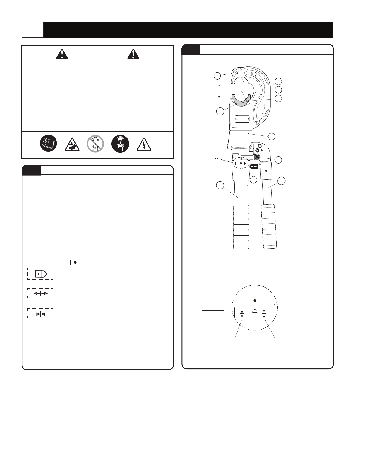
1.2
Die/Head
Release Pin
Complete Ram
Detail A
Handle Grip
Detail A
Operating Position
FIGURE 1
OVERALL VIEW
30
“ 56.1
mm 24
)*(
202
200
49
Latch
Reference Symbol
Rest Position
Die/Head Retaining Pin
32
Die/Head Release Pin
36
Die/Ram Retaining Pin
37
Tool Body
13
65
Complete
Movable
203
Handle
Release Position
TA02982 E page 2 of 8
Page 3
2.0 INSTRUCTION FOR USE
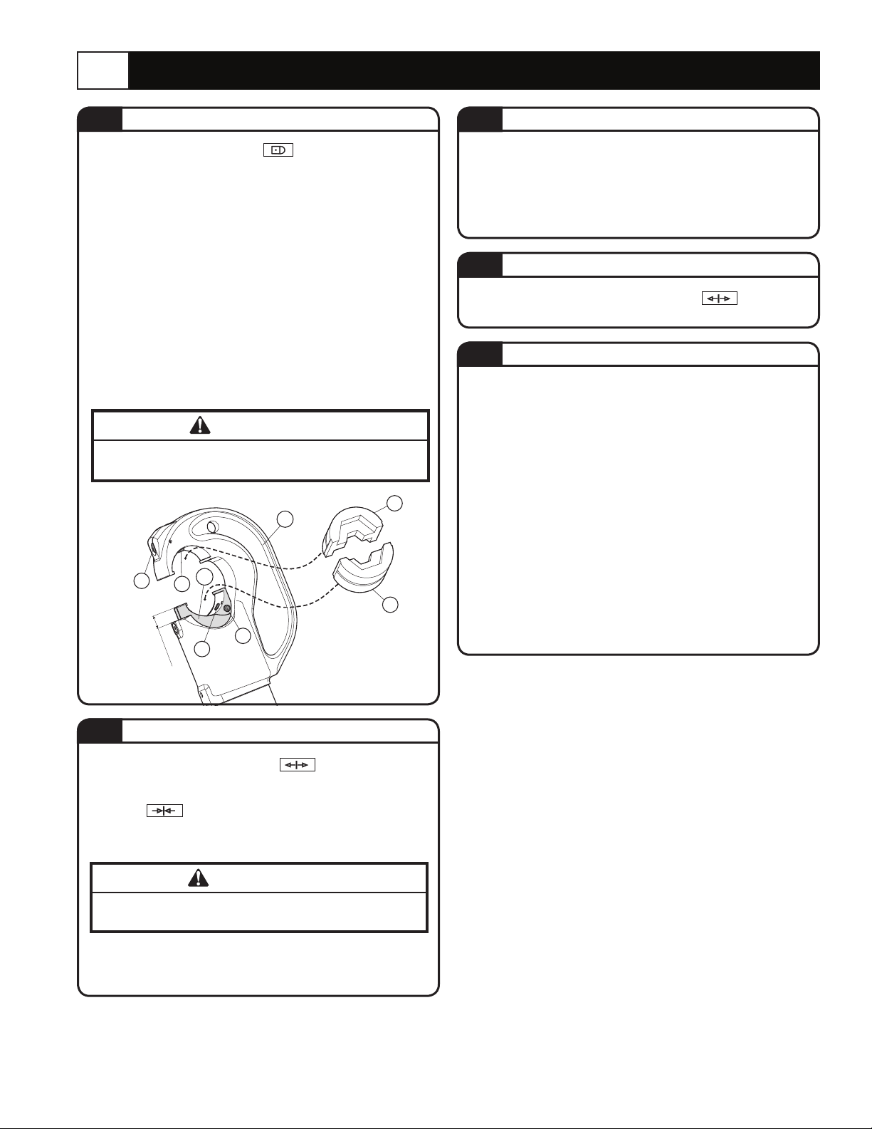
2.1
With the tool in the rest position prepare the tool as
follows: (see Figure 2)
− Select the appropriate die set for the connector.
− Insert the die (91) in the upper seat of the tool head until it is
locked by die/head pin (32). To ease the die insertion, keep
die/head release pin (30) depressed.
− Operate the tool (per 2.2) to advance the ram (202) 8-10 mm
(0.3 - 0.4 in.) and insert the die (90) into the seat on the ram
until it is locked by die/ram retaining pin (37). To ease this
operation, keep die/ram release pin (36) depressed.
− Insert the conductor in the connector.
− Position the connector between the dies and ensure the
correct location of the crimp.
− For ease of operation, the tool head can rotate through 180°.
PREPARATION
WARNING
DO NOT ATTEMPT TO TURN THE HEAD IF THE
HYDRAULIC CIRCUIT IS PRESSURISED.
91
201
32
~ 8 ÷ 10 mm
)
202
90
36
37
30
(0.3 - 0.4 in.
FIGURE 2
2.3
− Continue operating the movable handle (203). The tool will
automatically change over to the high pressure stage. The ram
will advance until the dies meet.
− Continue pumping until the maximum pressure valve is
activated and a “click” is heard.
2.4
− Rotate the xed handle to release position
handles. The ram will then retract, and the dies will open.
2.5
To replace dies proceed as follows: (Refer to Figure 2)
Upper die (91)
− Take the die off its guide by pushing the die/head release
pin (30).
− Insert replacement die until secured by the die/head retaining
pin (32).
Lower die (90)
− Take the die off its guide by pushing the die/head release
pin (36).
− Insert replacement die until secured by the die/ram retaining
pin (37). To facilitate this operation an advancement of the ram
by 8-10 mm (0.3 - 0.4 in.) is suggested.
COMPRESSION
RELEASE OF DIES
Close
DIE REPLACEMENT
2.2
− Set the tool in the release position by rotating the xed
handle (200). The moveable handle (203) will be released and
the main handle will rotate automatically to the operating
position .
− Operate moveable handle (203) for lower die advancement.
This rst stage rapidly closes the dies to the connector.
DIE ADVANCEMENT
WARNING
Never place the tool under pressure without inserting the
dies, this could cause damage to the head and the ram.
Make sure the dies are exactly positioned on desired crimp point,
otherwise re-open dies following instructions as per 2.4 and
reposition the connector.
TA02982 E page 3 of 8
Page 4

3.0 MAINTENANCE
Compliance with the following points should help to maintain the optimum performance of the tool.
3.1 3.5
Dust, sand and dirt are a danger for any hydraulic device.
Every day, after use, the tool must be cleaned with a clean
cloth, taking care to remove any residual particles, especially
close to pivots and moveable parts.
3.2
When not in use, the tool should be put in the rest position
and placed in the plastic case for storage and transportation.
The plastic case can also accommodate 14 die sets
(See Figure 3).
To put the tool in the rest position:
−
Retract the ram completely
as describe in 2.4.
− Keeping the handles
completely closed, release
the xed handle which will
rotate automatically to the
rest position . The
moveable handle will then
be locked by means of the
handle latch (49).
CLEANING
STORAGE
Every six months, check the oil level in the reservoir.
If necessary, bring the oil level up to the top lip of the
reservoir, see section 3.4 , a, b, c, e, g, h and i.
− Always use clean recommended oil, see section 1.1, pg. 2.
−
−
IMPORTANT: Ensure that disposal of used oil is in
accordance with current legislation.
3.6
200
FIGURE 3
ADDING OIL
Do not use old or recycled oil.
Do not use hydraulic brake uid.
TOOL POSITION
A
54
53
1
3.4
Air in the hydraulic circuit may affect the performance
of the tool (e.g. no lower die advancement; slow
advancement of lower die; lower die pulsating).
See Figures 4 and 5.
To purge air bubbles from hydraulic circuit:
a. Hold tool upright with the head in a vice and handles
open (Figure 4).
b. Using a 2,5mm allen key, remove screws (17 and
56), slide off the xed handle (200) to expose the oil
reservoir (3). Recover spring (54) and spring cover (53).
c. Remove reservoir cap (1).
d. Operate the moveable handle (203) three or four times
to advance the ram (202).
e. Depress pressure release pin (65) until ram is fully
retracted.
f. Repeat points d and e at least ve times, to ensure all
air bubbles in the hydraulic circuit are purged into the
reservoir.
g.
If the oil level is low, top off as directed in paragraph 3.5.
h. Replace the cap (1).
i. With the tool in the horizontal position, relocate spring
(54) and spring cover (53) in seat A (see detail in Fig. 4).
Reassemble the xed handle (200), insert screws (17
and 56) complete with washers (55) in their respective
positions and tighten them.
If the tool continues to malfunction, return the tool for
service/repair as detailed on page 8.
PURGING AIR BUBBLES
55
17
56
55
65
FIGURE 4 For Maintenance Operations
3
203
TA02982 E page 4 of 8
Page 5

4.0 PARTS LIST For Type 2
See Figure 5 for complete tool assembly.
Code N° Item Description Qty
6800040 1
6720100 3
6360260 8
6040685 8
6900621 9
6360160 10
6740060 11
6520765 12
6160044 13
6740140 14
6520180 15
6340566 16
6900059 17
6100037 18
6900211 27
6100035 28
6340540 34
6362035 38
6362010 39
6641140 40
6360240 41
6362020 42
6620382 43
6700100 46
6560420 48
6600101 53
6520862 54
6640205 55
6900080 56
6340720 57
6520861 58
6635011 59
6895050 60
6740120 61
6600100 62
6520260 63
6740080 64
6620120 65
6360120 66
The items marked with (K) are those that Thomas & Betts
recommends replacing if the tool is disassembled.
These items are supplied on request in the
“TBM14MC Spare Parts Package”
RESERVOIR CAP
OIL RESERVOIR
O-RING
GUIDING RING
SUCTION SCREW
O-RING
BALL
SPRING
TOOL BODY
BALL
SPRING
DOWEL
SCREW M4x8
KEY
SCREW M5x10
KEY
GRUB SCREW
SEAL
SEAL
BACK-UP RING
O-RING
SEAL
PUMPING RAM
CIRCLIP
PIN
SPRING COVER
SPRING
WASHER
SCREW M4x8
GRUB SCREW
SPRING
PIN
COMPLETE VALVE
BALL
BALL SUPPORT
SPRING
BALL
PIN
O-RING
1
1
1
2
1
2
2
2
1
2
2
2
2
1
1
1
1
1
1
1
1
1
1
4
2
1
1
2
1
1
1
1
1
1
1
1
1
1
1
Code N° Item Description Qty
6040060 67 BACK-UP RING 1
6080080 68 BUSH 1
K
K
K
K
K
K
K
K
K
K
K
K
K
K
K
K
K
6232589 77 TA04568 LABEL 1
6170143 88 PLASTIC CAP 2
6480407
6380265
6370238
6620245
6760160
6620440
6522006
6340540
6800088
6620250
6620312
6700250
6170140
6362058
6040128
6520619
6520611
6300079
6522006
6760040
6620445
6620320
6480196
6760320
6200032
6760280
6480269
6380240
6900280
6180200
The warranty is void if parts used are not original Thomas & Betts parts.
When ordering spare parts always specify the following:
− Code Number of Item
− Name of Item
− Type of Tool
− Tool Serial Number
200
200
201
201
201
201
201
201
201
201
202
202
202
202
202
202
202
202
202
202
202
202
203
203
203
203
203
203
203
203
COMPLETE MAIN
HANDLE
2 HANDLE GRIP 1
COMPLETE
INSULATED HEAD
30 PIN 1
31 PIN 1
32 PIN 1
33 SPRING 1
34 GRUB SCREW 1
75 PLASTIC CAP 1
76 PLASTIC CAP 1
COMPLETE RAM 1
19 CIRCLIP 1
20 COVER 1
21 SEAL 1
22 BACK-UP RING 1
23 SPRING 1
24 SPRING 1
25 RAM GUIDE 1
33 SPRING 1
35 PIN 2
36 PIN 1
37 PIN 1
COMPLETE
MOVEABLE HANDLE
44 SPLIT PIN 1
49 LATCH 1
50 SPLIT PIN 1
51 MOVEABLE HANDLE 1
MOVEABLE HANDLE
52
GRIP
69 SCREW M5x18 1
70 NUT 1
TA02982 E page 5 of 8
K
1
1
K
K
1
1
Page 6

1
46
44
50
48
203
51
49
70
46
52
16
69
68
15
16
14
43
65
15
42
14
41
66
67
13
40
39
12
53
54
17
8
55
59
55
11
61
56
57
58
62
18
63
12
60
10
9
10
11
7
34
64
17
3
200
2
77
38
19
20
24
25
23
35
33
37
35
36
FIGURE 5 Complete Tool Assembly for Type 2
Serial number
21
22
201
x
x
x
x
x
x
202
88
34
32
75
33
76
28
30
31
27
88
TA02982 E page 6 of 8
Page 7

5.0 PARTS LIST for Older Models
CODE N° ITEM DESCRIPTION QTY.
6800040
6380265
6720100
6480043
6780114
6360260
6040685
6900621
6360160
6740060
6520765
6160044
6740060
6520765
6740140
6520180
6340566
6900059
6700250
6170140
6100037
6520619
6520611
6300081
6620317
6900022
6100038
6760160
6620245
6340540
6522006
6620440
6370219
6362035
6040320
6360420
6362010
6641140
6360240
6362020
6620382
6760320
6780265
6700100
6080060
01
●
02
03
●
04
●
05
★
06
07
08
★
09
★
10
★
11
12
★
13
★
14
★
15
★
16
17
18
▲
19
▲
20
21
▲
22
▲
23
▲
24
▲
25
26
27
■
28
■
29
■
30
■
31
■
32
■
33
★
34
★ ▲ 35
★ ▲ 36
★
37
★
38
★
39
★
40
41
✚
42
✚
43
★
44
✚
45
1
1
1
1
1
1
2
1
1
1
1
1
1
1
1
1
1
1
1
1
1
1
1
1
1
1
1
1
1
1
1
1
1
1
1
1
1
1
1
1
1
1
1
4
4
Reservoir Cap
Fixed Handle Grip
Oil Reservoir
Fixed Handle
Fixed Handle Support
O-Ring
Guiding Ring
Suction Screw
O-Ring
3/16” Ball
Suction Spring
Body
3/16” Ball
Suction Spring
9/32” Ball
Spring
Ball Positioning Dowel
M 4x8 Screw
Ø 36 Circlip
Spring Cover
Key
Ram Return Outer Spring
Ram Return Inner Spring
Ram Spring Guide
Ram
M3x8 Screw
Key
D.3x28 Spring Pin
Die/Head Release Pin
M 10x8 Grub Screw
Spring
Die/Head Retainer Pin
“C” Head
Seal
Back-Up Ring
O-Ring
Seal
Back-Up Ring
O-Ring
Seal
Pumping Ram
D.5x30 Spring Pin
Moveable Handle Support
Circlip
Movable Handle Bushing
CODE N° ITEM DESCRIPTION QTY.
6560420
6760280
6200032
6480269
6380240
6760014
6232006
6340720
6520861
6635011
6740140
6520180
6340566
6180200
6900280
6080080
6620445
6760040
6522006
6620320
6040060
6360120
6620120
6340540
6740080
6520260
6600100
6740120
6360160
6895050
6900080
6640205
6760040
6520862
6600101
6640205
6900059
6480407
6620318
6370237
6480196
6000058
46
✚
47
✚
48
✚
49
✚
50
●
51
52
55
56
57
★
58
★
59
60
✚
61
✚
62
63
▲
64
▲
65
▲
66
▲
67
★
68
★
69
70
71
★
72
73
74
★
75
★
76
77
78
79
▲
80
★
81
★
82
83
84
2
1
1
1
1
1
1
1
1
1
1
1
1
1
1
1
1
1
1
1
1
1
1
1
1
1
1
1
1
1
1
1
1
1
1
1
1
Moveable Handle Pivot
D.4x30 Spring Pin
Movable Handle Latch
Moveable Handle
Movable Handle Grip
3x4 Spring Pin
Label (TG. 0356)
Pressure Release Dowel
Pressure Release Spring
Pressure Release Pin
9/32” Ball
Non Return Spring
Ball Positioning Dowel
M5 Nut
M 5x18 Screw
Pressure Release Ram Bushing
Die/Ram Release Pin
D. 3x8 Spring Pin
Spring
Die/Ram Retainer Pin
Back-Up Ring
O-Ring
Pressure Release Pin
M 10x8 Grub Screw
5/16” Ball
Spring
Ball Positioning Dowel
7/32” Ball
O-Ring
Max Pressure Valve
M 4x8 Screw
Washer
D. 3x8 Spring Pin
Spring
Spring Cover
Washer
M 4x8 Screw
Complete Main Handle
Complete Ram
Complete “C” Head
Complete Moveable Handle
Spare Parts Package
●
▲
■
✚
★
The items marked with ( ) are those Thomas & Betts
recommends replacing if the tool is disassembled.
These items are supplied on request in the
“TBM14MC Spare Parts Package”
The warranty is void if parts used are not original
Thomas & Betts parts.
When ordering spare parts always specify the following:
− Code Number of Item
− Name of Item
− Type of Tool
− Head Serial Number
TA02982 E page 7 of 8
Page 8

68
69
70
71
72
73
74
75
76
77
78
79
80
B-B
84
83
82
81
29
28
27
E-E
26
25
67
66
65
64
63
62
61
60
59
58
57
56
55
24
23
22
21
20
19
18
17
16
15
14
13
12
E
B
E
B
F
11
10
H
H
09
08
07
30
31
32
33
34
35
36
37
38
39
40
41
42
43
44
45
46
47
48
49
50
06
05
52
04
03
02
01
H-H
51
FIGURE 6 Complete Tool Assembly for Older Models
In case of a breakdown contact the Thomas & Betts Tool Service Center at 1-800-284-TOOL (8665).
WARRANTY: Thomas & Betts sells this product with the understanding that the user will perform all necessary tests to
determine the suitability of this product for its intended use. Thomas & Betts manufactures its goods and tools in a manner
to be free of defects. Should any defect occur in its goods within two (2) years (or tools within time stated on warranty card) of
date of purchase, Thomas & Betts, upon prompt notication, will at its option, exchange or repair the goods or tools or refund
the purchase price. Proof of purchase required.
Limitations and Exclusions: THIS WARRANTY IS IN LIEU OF ALL OTHER REPRESENTATIONS AND EXPRESSED AND
IMPLIED WARRANTIES (INCLUDING THE IMPLIED WARRANTIES OF MERCHANTABILITY AND FITNESS FOR USE),
AND UNDER NO CIRCUMSTANCES SHALL THOMAS & BETTS BE LIABLE FOR ANY INCIDENTAL OR CONSEQUENTIAL
DAMAGES OR LOSSES OF ANY KIND.
Thomas & Betts Corporation
Memphis, Tennessee
Website: www.TNB.com
© 2010 Thomas & Betts Corporation. All Rights Reserved.
TA02982 E page 8 of 8
 Loading...