

Page 1
NEW WORK CEILING FAN
AND LIGHT FIXTURE BAR HANGER
INSTRUCTION SHEET
Individual Cat. No
54151CFB-BHL...............
READ ALL INSTRUCTIONS AND WARNINGS CAREFULLY BEFORE PROCEEDING!
New Work Bar Hanger with 1-1/2" Deep Box. (Metallic Ceiling Fan Box)
WARNING
DISCONNECT THE ELECTRICAL CIRCUIT SUPPLYING POWER
TO THE OUTLET PRIOR TO INSTALLATION.
CAUTION
TO PREVENT INJURY, THE HANGER MUST BE SECURELY
INSTALLED IN ACCORDANCE WITH THESE INSTRUCTIONS
BEFORE MOUNTING OR CONNECTING A CEILING FAN OR
LIGHT FIXTURE.
AFTER INSTALLATION OF THE HANGER, BE SURE TO
FOLLOW ALL MOUNTING INSTRUCTIONS WITH THE CEILING
FAN OR LIGHT FIXTURES.
—CONSULT A QUALIFIED ELECTRICIAN IF YOU HAVE ANY QUESTIONS. —
IMPORTANT SAFETY NOTICE: USE ONLY METALLIC BOX AND SCREWS PROVIDED IN KIT. DO NOT SUBSTITUTE!
INSTALLATION INSTRUCTIONS:
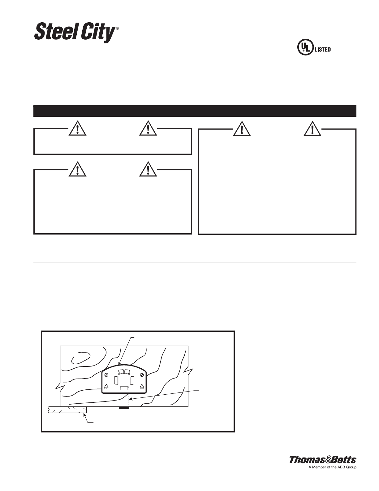
1. Expand the bar hanger to the length of spacing between the wood
ceiling joists. If the drywall is 1/2" thick, the locating tabs on the
end-plates can be used to position the hanger. If the drywall is
thicker than 1/2", the locating tabs need to be broken off and the
end plate is positioned to make the bottom of box ush with
drywall. (See Figure 1).
D
O NOT EXCEED MAXIMUM WEIGHT RATINGS
FOR 16” SPANS
MAX LIGHT FIXTURE = 200 LBS.
MAX CEILING FAN = 70 LBS.
FOR 24” SPANS
MAX LIGHT FIXTURE = 90 LBS.
MAX CEILING FAN = 70 LBS.
INSTALL THIS BAR HANGER SUPPORT ONLY IN
ACCORDANCE WITH APPLICABLE NATIONAL AND LOCAL
BUILDING AND ELECTRICAL CODES.
CAUTION
Figure 1
TA04763 D Page 1 of 2
END-PLATE
LOCATING
TAB
Reference drywall ush with bottom of box.
Page 2
#12-14 X 1" LONG SCREW (4)
OVERLAP
BOX SUPPORT
BRACKET
FAN MOUNTING
SCREWS
SPURS (4)
Figure 2
INSTALLATION INSTRUCTIONS - continued
WARNING
DO NOT USE THE SPURS AS SOLE MEANS OF SUPPORT FOR THE HANGER.
2. Use a hammer to strike the engaging spurs into the wood ceiling joist. This will provide temporary support for
the hanger.
3. Using the holes in the end plates of the hanger as a template, drill (4) 7/64˝ diameter pilot holes 3/8˝ deep
(MAX.). Use the wood screws provided and install securely through holes of the end plates. (See Figure 2).
4. Align and fasten the box support bracket along the hanger where the outlet box is to be mounted on the hanger.
WARNING
THE BOX SUPPORT BRACKET MUST BE POSITIONED WITHIN THE OVERLAP
OF THE TWO CHANNELS (SEE FIGURE 2).
5. Attach the ceiling fan box by aligning the two holes on either side of the bottom center knockout with the two
holes in the box support bracket.
• Drive the provided #10-32 x 5/8" fan mounting screws with lockwashers into each of the two holes through
the box fastener (See Figure 2).
IMPORTANT SAFETY NOTICE: MOUNTING OF METALLIC AND NON-METALLIC CEILING FAN BOXES REQUIRES DIFFERENT
SCREWS. IF INCORRECT SCREWS ARE USED, THE BOX MAY DISLODGE FROM THE HANGER ASSEMBLY. ONLY USE #10-32 x 5/8"
SCREWS WITH LOCKWASHERS FOR STEEL CITY METALLIC CEILING FAN BOXES. ONLY USE #10-32 x 5/8" SCREWS WITHOUT
LOCKWASHERS FOR UNION
WARRANTY: Thomas & Betts sells this product with the understanding that the user will perform all necessary tests to determine the suitability of this product for the user's intended application.
®
NON-METALLIC CEILING FAN BOXES. DO NOT INTERCHANGE SCREWS.
Limitations and Exclusions: THE ABOVE WARRANTY IS THE SOLE WARRANTY CONCERNING THIS PRODUCT, AND IS IN LIEU OF ALL OTHER WARRANTIES EXPRESS OR IMPLIED,
INCLUDING BUT NOT LIMITED TO ANY IMPLIED WARRANTY OF MERCHANTABILITY OR FITNESS FOR A PARTICULAR PURPOSE, WHICH ARE SPECIFICALLY DISCLAIMED. LIABILITY
FOR BREACH OF THE ABOVE WARRANTY IS LIMITED TO COST OF REPAIR OR REPLACEMENT OF THE PRODUCT, AND UNDER NO CIRCUMSTANCES WILL THOMAS & BETTS BE
LIABLE FOR ANY INDIRECT, SPECIAL, INCIDENTAL OR CONSEQUENTIAL DAMAGES.
Thomas & Betts Corporation
Memphis, Tennessee
© 2013 Thomas & Betts. All Rights Reserved. TA04763 D Page 2 of 2
www.tnb.com
 Loading...