

Page 1

Operating Instructions
FOR HMC5750-LI
HYDRAULIC COMPRESSION TOOL
Table of Contents
Page
1.0 GENERAL INFORMATION......................................................... 2
1.1 Safety Rules........................................................................... 2
1.2 Features................................................................................. 2
1.3 Specifications......................................................................... 2
2.0 Parts & Accessories .................................................................. 3
2.1 Hydraulic Compression Tool................................................... 3
2.2 Battery. .................................................................................. 3
2.3 Charger. ................................................................................. 3
2.4 Carrying Case ........................................................................ 3
3.0 Operating Instructions .............................................................. 4
3.1 Charging the Battery. ............................................................. 4
3.2 Attaching & Detaching the Battery. ......................................... 4
3.3 Compression Cycles .............................................................. 4
TA04748 A Page 1 of 8
Page
3.4 Switch Operations.................................................................. 4
3.5 Compression Operation ......................................................... 5
3.6 Maintenance & Operation....................................................... 5
3.7 Trouble Shooting .................................................................... 5
4.0 Important Operation Precautions ............................................ 6
4.1 Precautions for the Compression Tool .................................... 6
4.2 Precautions for the Battery. .................................................... 6
4.3 Precautions for the Charger.................................................... 6
5.0 Parts Breakdown....................................................................... 7
5.1 Parts Diagram ........................................................................ 7
5.2 Parts List................................................................................ 8
Page 2
IMPORTANT: Read and understand all of the
instructions and safety information in this manual
before operating or servicing this tool.
1.0
1.1
1. BE FAMILIAR WITH YOUR TOOL.
Read the instruction manual. Become aware of its proper
usage as well as the potential hazards.
2. KEEP WORK AREA CLEAN AND WELL LIGHTED.
Poor lighting and cluttered areas invite accidents.
3. USE SAFETY GLASSES.
4. MAINTAIN TOOL WITH CARE.
Keep tool in good condition at all times. Keep it clean for
best and safest performance.
5. DON'T OVER-REACH.
Keep proper footing and balance at all times.
6. NEVER ATTEMPT TO MAKE A COMPRESSION ON A
"HOT" LINE.
Never assume the power is OFF! Determine beforehand if
any electrical hazards could exist when making a
connection to a line or wire.
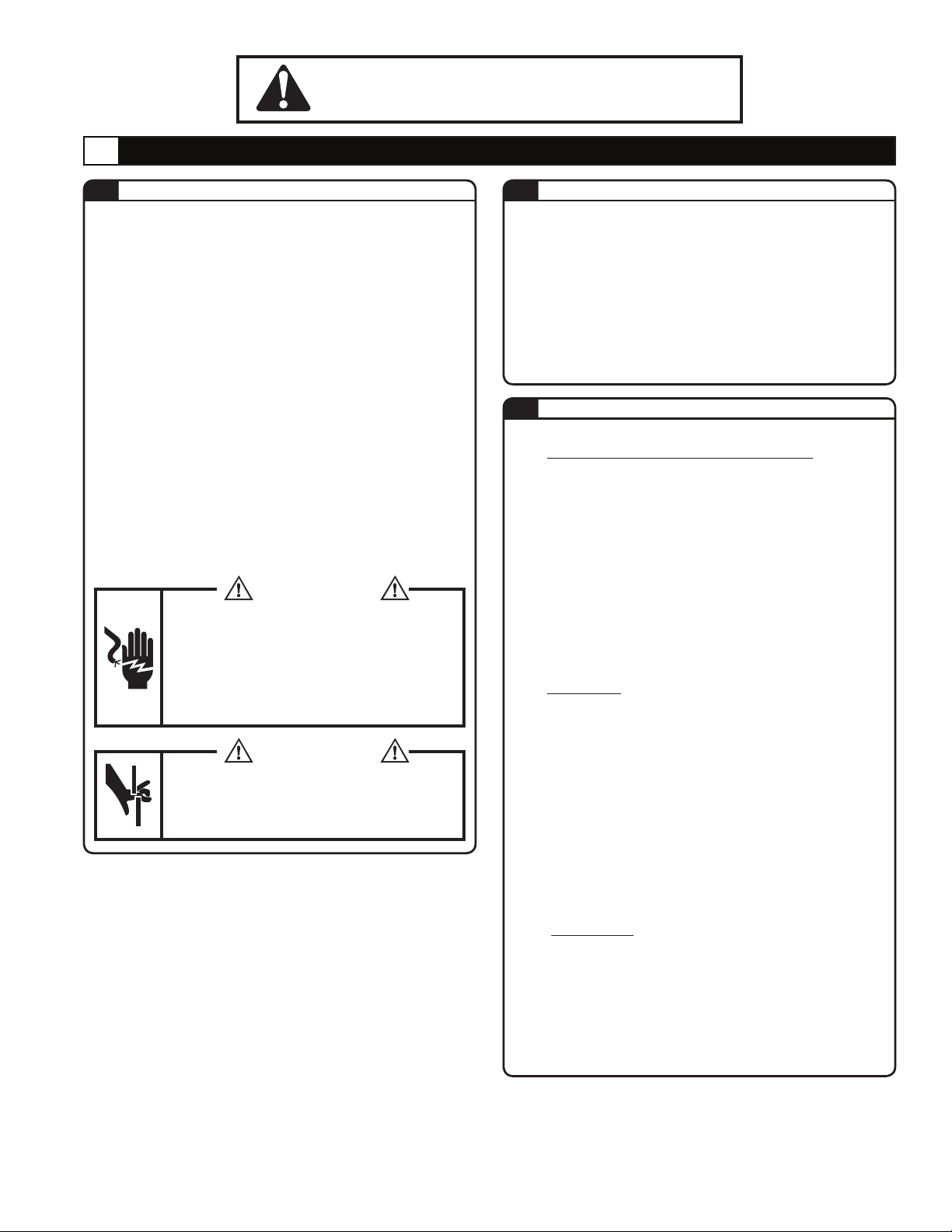
7. KEEP FINGERS AND OTHER BODY PARTS AWAY
FROM INDENTING NIBS & MOVING PARTS.
SAFETY RULES
GENERAL INFORMATION
WARNING
Tools are NOT insulated for use on or near
energized conductors. Use of these tools
near energized conductors may lead to
electrical shock, causing severe injury or
death. DO NOT use these tools near
energized conductors without adequately
insulating operator and surroundings.
WARNING
Pinch point hazard. Indenting Nibs at high
force can cause severe personal injury. Keep
all body parts away from moving parts of the
tool during operation.
FEATURES1.2
• Fully automatic, self-contained power tool.
• Removable battery cartridge - simply change the
cartridge for continuous use.
• One handed operation - control ram advancement
and retraction with one hand.
• Designed to crimp connectors manufactured to
ANSI C119.4.
• 360º rotating head, no dies required.
1.3
SPECIFICATIONS
HYDRAULIC COMPRESSION TOOL:
HMC5750-LI
Drive Unit: 1
Dimensions:
Weight:
Output:
Capacities:
Jaw Opening:
4.4V DC Motor
15”L x 2.5”W x 13”H
12.5 lbs. with battery
6 Tons
Up to 750 kcmil Cu
1.50”
BATTERY:
144-BAT-LI
Battery Type: Sealed Lithium Ion
Voltage:
Dimensions:
Capacities:
Weight:
Charging time:
45 min. 100% Capacity
14.4V DC
4.2”L x 3.3W x 2.6H
3.0Ah
1.2 lbs.
25 min. 80% Capacity
CHARGER:
144-CHR-LI
Input Voltage: 120 - 240 V AC Single Phase
Dimensions:
Weight:
9”L x 5.7W x 3.2H
3.5 lbs.
TA04748 A Page 2 of 8
Page 3

2.0
PARTS AND ACCESSORIES
2.1
2.3
HYDRAULIC COMPRESSION TOOL
(HMC5750-LI)
Head Latching Pin
Indenting
Nibs
Advance Trigger
Release Button
Hanging Strap
CHARGER (144-CHR-LI
LED
Indicator
Hanging
Strap
)
2.2
Release
Button
2.4
Air Vent
BATTERY (144-BAT-LI
Contact Cover
Air Vent
CARRYING CASE
)
Contacts
LED Lamp
Power Cord Inlet
Contacts
Air Vent
Power Cord
TA04748 A Page 3 of 8
Page 4

3.0
OPERATING INSTRUCTIONS
3.1
CHARGING THE BATTERY
1. Connect the power cord to the Charger 144-CHR-LI and to an AC
outlet. The LED Lamp blinks in Red [STAND BY]
NOTE: The rated input voltage for this unit is 100V-240V. Use of
voltages over 260V will result in damage to the charger.
2. Insert the Battery rmly into the charger.
The LED Lamp lights in green [CHARGING].
NOTE: Do not short-circuit the Charger by placing foreign materials
in the contacts on Charger, as this will damage the Charger.
3. Charging takes approximately 25 minutes (80% capacity) and
45 minutes (100% capacity).
When charging is nished, the LED Lamp lights in orange
[COMPLETION].
NOTE: If the LED Lamp displays solid red [HIGH TEMPERATURE],
remove the Battery from the Charger and allow it to cool down
before trying to charge it again.
4. When the battery will no longer charge or hold a charge, the LED
Lamp blinks quickly in red [IMPOSSIBLE TO CHARGE].
5. When the charger is out of order, the LED Lamp does not light up
even if AC power is supplied.
NOTE: Do not power the Charger with a portable generator.
3.2
ATTACHING & DETACHING THE BATTERY PACK
3.3
Battery
LED Lamp
Power Cord
Charger
COMPRESSION CYCLES
1. To attach the Battery, slide it into the base of the Tool
until it stops and the Latches engage.
2. After inserting the Battery, check that it is securely in
place by pulling it gently without pressing the Latches.
3. To detach the Battery, pull out the Battery while pressing
the Latches.
Tool
Battery
This guide indicates the number of compression cycles that
the HMC5750-LI can be expected to perform when the
battery is fully charged. These gures are approximate and will
vary according to the charging and other operating conditions,
such as temperature, humidity, and battery condition.
AVERAGE COMPRESSIONS
CONDUCTOR
PER CHARGE
144-BAT-LI
1/0 Cu / Al
4/0 Cu / Al
750 kcmil
3.4
100 - Conductor size is not a major
factor on this dieless tool. It
performs approximately the same
on all sizes.
SWITCH OPERATIONS
1. The indenting nibs extend when the Trigger is depressed
and stops when the Trigger is released.
2. To retract the indenting nibs, depress the Release Button.
The indenting nibs continue to retract while the Release
Button is depressed.
Trigger
Latches
(both sides)
Pull Out
Slide in
Release Button
TA04748 A Page 4 of 8
Page 5
3.5
COMPRESSION OPERATION
1. Not all connectors are suitable for dieless tool applications.
Check your connector manufacturer recommendations on
using a dieless compression tool with the connector and
cable being used.
2. Retract the indenting nibs by pressing the release button.
3. Make sure the head is closed in the latched position and
that the head latching pin is fully inserted. Position the
connector, and center it between the indenting nibs. Activate
the trigger and advance the nibs so the connector is held in
place, but not yet deformed. Check connector for correct
positioning.
4. Insert the cable into the connector and activate the trigger
until the compression is completed. The LED indicator
(Step 2.1) on either side of the tool will show GREEN when a
complete compression is made. A RED indicator light will
show if the compression is incomplete, due to early release
of the trigger or a low battery. An ORANGE indicator will
show if the battery is getting low, but the compression is still
completed.
5. Press release button to retract the indenting nibs and
remove the connector from the tool. If necessary, pull the
head latching pin to unlatch the head for easier removal of
the connector from the tool.
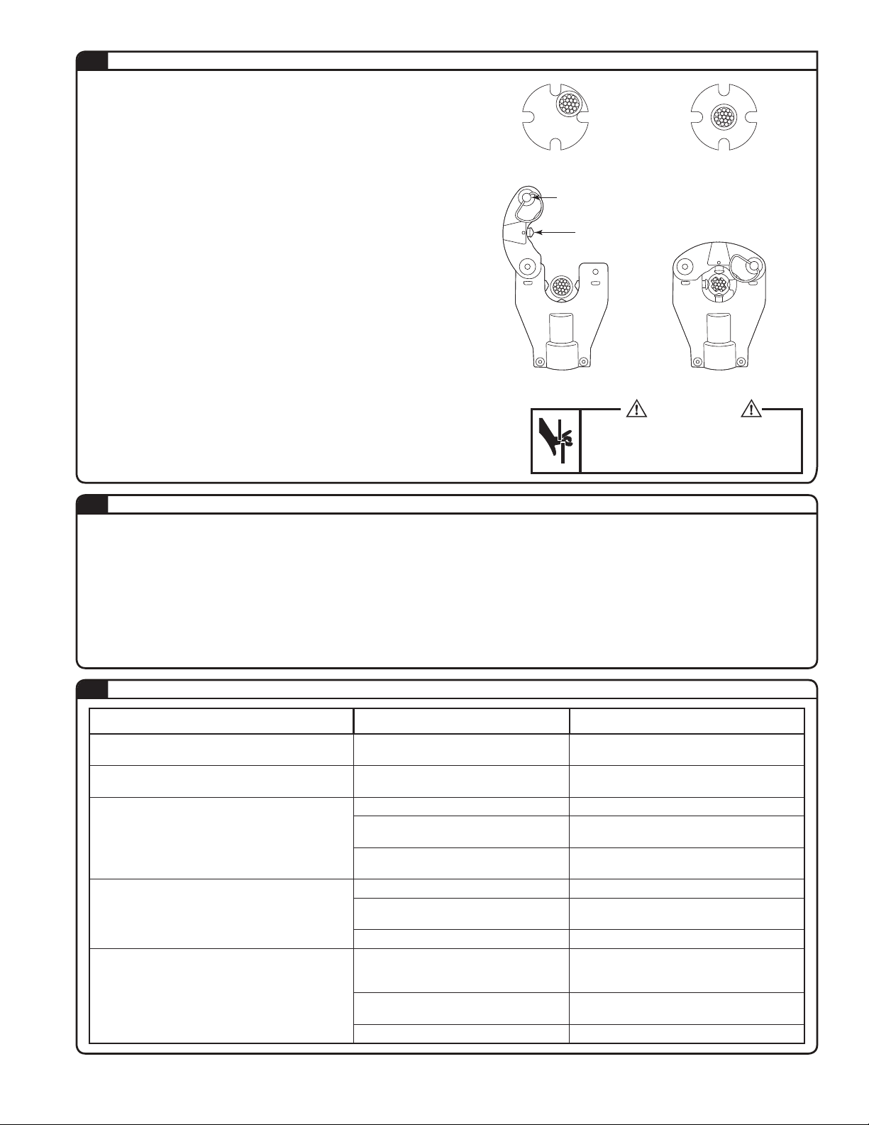
WRONG CORRECT
Head Latching Pin
Indenting Nibs (4)
UNLATCHED LATCHED
WARNING
Pinch point hazard. Compressing identing
nibs at high force can cause severe personal
injury. Keep all body parts away from moving
parts of the tool during operation.
3.6
MAINTENANCE & INSPECTION
1. Very little maintenance is required to ensure that the tool is kept in good working condition.
2. To ensure smooth operation and prevent rust, store the tool in a cool dry area. Ensure that moving parts are lubricated regularly.
3. When the plastic housing becomes dirty, clean it with a soft soaped cloth.
4. Dust, sand, and dirt are a danger for any hydraulic device. After each use, the tool should be wiped with a clean cloth taking care
to remove any residue, especially close to the movable parts.
5. If the tool is maintained regularly, it should provide you with trouble free service.
NOTE: Always remove the battery pack from the unit before replacing parts or maintenance.
3.7
TROUBLE SHOOTING
Problem Cause Solution
Charger LED lamp indicates stand by while battery
is inserted.
The charger LED lamp indicates high or low
temperatures.
The motor does not operate at all.
The motor runs but nibs will not extend or nibs
extend but will not build pressure.
The nibs will not retract
There is dust or foreign objects lodged at
the battery contacts.
The battery is too hot or cold.
The battery is not charged. Charge the battery.
There is dust or foreign objects lodged at
the battery contacts.
The switch is misaligned.
Insufcient hydraulic oil.
Air in hydraulic system.
Defective hydraulic circuit. Consult tool service.
Tool did not complete a full cycle and
bypass.
The connector is jammed in indenting nibs.
The release button is bent or misaligned. Consult tool service.
Remove foreign objects.
Allow the cartridge to reach room temperature
before continuing.
Remove foreign objects.
Check to see if switch is aligned with trigger,
consult tool service.
Consult tool service.
Hold the tool with head towards the oor to
allow air to rise towards top of oil bladder.
Depress trigger and allow tool to reach full
pressure and bypass, then depress release
button to retract the nibs.
Depress and hold release button while prying
indenting nibs apart.
TA04748 A Page 5 of 8
Page 6

4.0
IMPORTANT OPERATING PRECAUTIONS
4.1
PRECAUTIONS FOR COMPRESSION TOOL
1. Not all connectors are suitable for dieless tool
applications. Check your connector manufacturer
recommendations on using a dieless compression tool.
2. Never operate the tool without a connector and cable in
place.
3. Always point the tool away from other people.
4. If the tool is stored for an extended period at a
temperature of less than 25º F (-5º C), the tool should be
allowed to return to room temperature to ensure smooth
operation. Use the tool only after it has been at room
temperature for 1 hour.
5. Do not drop the tool. Dropping the tool may damage the
hydraulic circuit and cause malfunctions.
6. Keep the head and indenting nibs clean and free of
debris. Solvents can be used to clean the head but
should not be used on the plastic body. Use soap &
water to clean the body.
4.3
1. The LED lamp lights up green and remains lit when the
unit starts charging a battery. The indicator turns orange
when charging is completed.
2. This unit is for charging battery 144-BAT-LI only. Do not
use the charger for any other devices.
3. Allow battery cartridges to cool before charging. Allow at
least 15 minutes between charges when charging several
batteries in succession.
4. Charge batteries at an ambient temperature of 50-95
degrees F (10-35 degrees C). Charging time is
approximately 25 minutes for 80% capacity and 45
minutes for 100% capacity.
5. Never short circuit the output contacts.
6. Do not expose the charger to water, oil or solvents.
7. Do not disassemble, modify, drop or otherwise abuse
the charger.
PRECAUTIONS FOR THE CHARGER
4.2
PRECAUTIONS FOR THE BATTERY PACK
1. Do not short circuit the contacts or expose the battery to
water, oil or solvents.
2. Do not disassemble or attempt to repair the battery or
dispose of in a re.
3. Do not drop or otherwise abuse the battery.
4. Do not leave the battery in locations where it will be
exposed to a temperature greater than 104 degrees F (40
degrees C) for an extended period.
5. The battery has a limited life. When the capacity
becomes about 1/2 that of the original capacity, the
battery should be replaced.
6. If the battery is stored without being charged, natural
drainage will cause the power to be reduced. The battery
should be charged every 3 months if not in use regularly.
WARRANTY: Thomas & Betts sells this product with the understanding that the user will perform all necessary tests to determine
the suitability of this product for the user's intended application. Thomas & Betts warrants that this product will be free from
defects in materials and workmanship for the period stated on the enclosed warranty card. Upon prompt notication of any
warranted defect, Thomas & Betts will, at its option, repair or replace the defective product. Misuse, misapplication or
modication of Thomas & Betts products immediately voids all warranties.
Limitations and Exclusions: THE ABOVE WARRANTY IS THE SOLE WARRANTY CONCERNING THIS PRODUCT, AND IS IN
LIEU OF ALL OTHER WARRANTIES EXPRESS OR IMPLIED, INCLUDING BUT NOT LIMITED TO ANY IMPLIED
WARRANTY OF MERCHANTABILITY OR FITNESS FOR A PARTICULAR PURPOSE, WHICH ARE SPECIFICALLY
DISCLAIMED. LIABILITY FOR BREACH OF THE ABOVE WARRANTY IS LIMITED TO COST OF REPAIR OR
REPLACEMENT OF THE PRODUCT, AND UNDER NO CIRCUMSTANCES WILL THOMAS & BETTS BE LIABLE FOR ANY
INDIRECT, SPECIAL, INCIDENTAL OR CONSEQUENTIAL DAMAGES.
TA04748 A Page 6 of 8
Page 7

5.0
PARTS BREAKDOWN
5.1
HMC5750-LI PARTS DIAGRAM
TA04748 A Page 7 of 8
Page 8

5.2
HMC5750-LI PARTS LIST
NO. DESCRIPTION CODE QTY NO. DESCRIPTION CODE QTY
M4 X 20 Screw 558-01
11
Housing (R) 1 60 P-8 Back-Up Ring (B.C.) 85-33 1
12
M3 x 6 Screw R150-02
13
Top Cover 1 62 PS-20 Pent Seal R150-24 1
14
Switch Unit 558-04 1 63 P-20 Back-Up Ring (B.C.) 35-18 1
15
LED Harness 558-05 1 64 Pump Piston (1) R150-25 1
16
Circuit Board 558-06 1 65 P-5 O-Ring 5N-35 1
17
Strap 558-07 1 66 Pump Piston (2) 150GM-01 1
18
M3 x 5 Screw ROB-94 1 67 P-3 O-Ring 16-36 1
19
Retaining Plate 458-01 1 68 Release Valve Stem ROB-135 1
20
Spring (639) 458-02 1 69 Spring (678) 558-17 1
21
Lever Stopper 558-08 1 70 Spring (66) 85-40 1
22
3 x 16 Parallel Pin 558-09
23
Switch Knob 1 72 Spring (67) 85-39 2
24
Spring R150-09 1 73 Valve Screw (10) 410-44 2
25
Housing (L) 558-11 1 74 P-42 O-Ring 9H-17 1
26
Power Unit 558-12 1 75 Ram Spring (388) UC-35 1
27
M4 x 14 Screw (NI) ROB-128B 4 76 P-28 O-Ring 300-21 1
28
Spring (598) R150-13 1 77 P-28 Back-Up Ring (B.C.) 55D-03 1
29
Push Pin R150-14 1 78 Ram UC-36 1
30
Release Lever 558-13 1 79 Retaining Screw UC-12 1
31
4 x 16 Dowel Pin (G) 24-01 1 80 P-6 O-Ring RB-70 1
32
Reservoir Cap 410-55 1 81 P-6 Back-Up Ring (B.C.) UC-28 1
33
Magnet ROB-25 1 82 M4 x 6 Screw (F.P.) 16-42 2
34
Oil Reservior R4412-01 1 83 4 x 30 Drive Pin (AW) UC-14 1
35
G-30 O-Ring 75-26 1 84 Cam Yoke Holder UC-32 1
36
M3 x 16 Screw R150-16 2 85 3 x 18 Drive Pin RF-33 1
37
Valve Block R150-17 1 86 Cam Yoke UC-33B 1
38
Spring (371) 51-71 1 87 Spring (390) 6H-11 2
39
3/16” Ball 16-49 3 88 NIB UC-34 2
40
SI-20 Ring 410-74 1 89 Roller UC-07 10
41
Filter Screen 410-73 1 90 Roller Retainer UC-08 2
42
Strainer R150-18 1
43
Valve Cartridge R150-19F 1
44
S-8 O-Ring R510A-08 1
45
P-7 O-Ring 16-60 1
46
SEPN4 Retainer R150-21 1
47
Plug 51-21 1
48
P-4 Back-Up Ring 410-47 1
49
P-4 O-Ring 410-48 1
50
Spring (341) 51-20 1
51
7/32” Ball 16-26 1
52
M4 x 4 Screw (F.P.) 85-47 3
53
1/8” Ball 40-20 2
54
M5 x 5 Screw (F.P.) 510A-05 1
55
5/32” Ball 22-21 1
56
Body 575-01 1
57
558-02
R558-03
558-10
6 59 PS-8 Pent Seal 16-44 1
1 61 Spring (590) R150-23 1
1 71 9/32” Ball 16-40 2
91 Side Jaw (C) 6H-10C 2
92 M6 x 30 Screw E3-49 2
93 M4 x 30 Screw ET-46 2
94 Roller 6H-08B 2
95 Head (1) 6H-07B 1
96 Head (2) 6H-09B 1
97 Pin (156) 6H-02A 1
98 Ce-8 Snap Ring 16-09 2
99 3 x 28 Drive Pin 38A-01 1
100 Slide Pin 6H-01A 1
101 M3 x 5 Screw UC-37A 1
102 Yoke 6H-01A 1
58 3 x 8 Dowel Pin (D) 610F-11 1
© 2013 Thomas & Betts. All Rights Reserved.
Thomas & Betts Corporation
Memphis, Tennessee
www.tnb.com
TA04748 A Page 8 of 8
 Loading...