

Thomas & Betts furse ESP 120 D1, furse ESP 415 D1 Series, furse ESP 208 D1 Series, furse ESP 277 D1, furse ESP 240 D1 Installation Instructions Manual
...Page 1

Installation instructions
for mains wire-in protectors
ESP D1, D1R, D1/LCD and D1R/LCD variants
Page 2

Installation instructions for mains wire-in protectors
Introduction
This document explains how to install Furse Electronic
Systems Protectors for mains power supplies:
Single phase ESP 120 D1 | Single phase ESP 240 D1 | Single
phase ESP 277 D1 | Three phase ESP 208 D1, D1R, D1/LCD
& D1R/LCD | Three phase ESP 415 D1, D1R, D1/LCD &
D1R/LCD | Three phase ESP 480 D1, D1R, D1/LCD & D1R/LCD
These instructions are prefaced by a summary of the
Key points of installation. Each key point is explained in
detail in the section entitled Installation.
WARNING: Incorrect installation will impair the
Contents
effectiveness of the ESP units
Key points of installation 3
Before installation 4
Installation 6
Installation check (LED units) 24
Neutral-earth warning light (LED units) 25
Status indication (LED units) 26
Status indication (LCD units) 26
LCD display settings 30
Remote indication 34
Maintenance 35
Application notes 36
Remote display cut-out template 39
Key points of installation
1
Install protectors very close to the power supply to be
protected, either within the distribution panel or directly
alongside it.
2
Mount units within a panel or WBX enclosure.
3
ESP D1 units can be installed in parallel or, for power
supplies ≤125A, in-line (series) with the power supply.
4
Connect to phase(s), neutral and earth.
NOTE: Units must have a neutral connection.
5
Units installed at power distribution boards can be
installed either:
on the load side of the incoming isolator, or
on the closest available outgoing way to the
incoming supply
6
Provide a means of isolation for the ESP unit.
7
The connecting leads to phase/live terminals should be
suitably fused (125A maximum) ensuring full
discrimination with the immediate upstream supply fuse.
Page |3Page |2
Page 3

Installation instructions for mains wire-in protectors
8
Connecting leads should be 10 mm2multi stranded
cable for parallel/shunt installation. For series installation,
refer to section 6.
9
For parallel/shunt installation, keep the connecting leads as
short as possible and ideally less than 25 cm (10 inches) in
length. For series installation, keep earth lead as short as
possible.
This may be better achieved with the equivalent D1R or
D1R/LCD unit with remote display mounting flexibility.
10
Bind the connecting leads tightly over their entire length.
Before installation
1
Check that the voltage between neutral and earth does
not exceed 10 volts.
If this voltage does exceed 10 volts, the installation
is unsafe.
Find and rectify the cause of this fault before proceeding.
(For delta supplies with no neutral, see page 13).
2
Make sure that the supply voltage is suitable for the unit.
Supply Rated Unit Voltage
Voltage Range
(V
)(V
ESP 120 D1
Phase to
RMS
RMS
Neutral/Earth 110/120/127 90-150
ESP 208 D1 Series
Phase to Phase 190/208/220 156-260
ESP 240 D1
Phase to
Neutral/Earth 220/230/240 200-280
ESP 415 D1 Series
Phase to Phase 380/400/415 346-484
ESP 277 D1
Phase to
Neutral/Earth 240/254/277 232-350
ESP 480 D1 Series
Phase to Phase 415/440/480 402-600
)
Page |5Page |4
Page 4
Installation
1
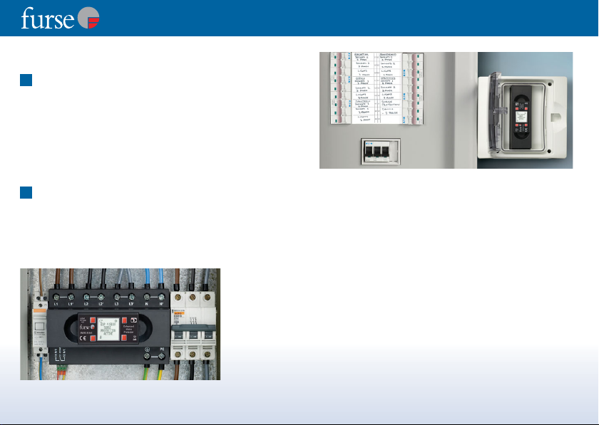
Location
Protectors need to be installed very close to the power
supply to be protected. Usually the protector will be
installed at a power distribution panel either inside it
(Figure 1) or right next to it (Figure 2).
ESP D1 protectors have been designed to fit onto a
standard 35mm DIN rail (see 3 - DIN Installation) or within
a Furse WBX D enclosure.
2
Enclose the ESP unit
The ESP unit has exposed terminals. For electrical safety,
the unit must be installed within a panel or enclosure.
For standard single and three phase units, where possible,
install the unit within the power distribution panel behind
a suitable viewing window.
Figure 1 ESP 415
D1/LCD
installed on
a DIN rail
within a
power
distribution
panel.
Installation instructions for mains wire-in protectors
Figure 2 - ESP 415 D1/LCD installed next to a power
distribution panel in a suitable WBX D enclosure.
Alternatively, for three phase units, a remote display option
is available. Units can be installed within the power
distribution panel with the remote display mounted on the
front of the panel (see 4 - remote display).
When mounting the units in existing metal panels or
enclosures, ensure that the enclosure is securely bonded
to the earth bar to which the ESP unit will be connected.
If it is not possible to install the unit within the distribution
panel it should be mounted in a separate enclosure,
see Figure 2, as close as possible to the distribution panel
(see 12 & 13 - Length of connecting leads). Gland the
enclosure onto the power distribution panel. Suitable
enclosures are available from Furse.
Page |7Page |6
Page 5
Installation instructions for mains wire-in protectors
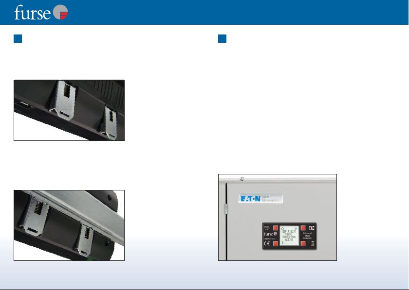
3
DIN Installation
ESP D1 Series protectors have been designed with an
innovative DIN foot for connection to standard 35mm DIN rails.
This DIN foot, comprising spring loaded steel DIN mounts,
enables rapid positioning of D1 protectors onto the rail.
Figure 3 - Reverse of
3 phase protector
showing innovative
spring loaded
DIN foot.
The spring loaded steel DIN mounts pull down and out
to lock into place ready for siting the protector.
Position the D1 protector at the preferred location on the
DIN rail and press the protector back to release the springs.
The protector locks into place.
Figure 4 - Reverse
of 3 phase protector
showing spring
loaded DIN foot
locked onto DIN rail.
Page |8
4
Remote display
Three phase ESP D1R and D1R/LCD units include a remote
mounting display to ensure optimum positioning of the
unit along with quick and easy status checking.
The remote display should be mounted in a clearly visible
position, typically on the front of the distribution panel
(see Figure 5).
For remote display connection, ensure the cable is of
sufficient length, and is unimpeded within the cabinet.
Allow a minimum of 60 mm behind the front panel for the
interconnection cable.
ESP D1R and D1R/LCD units are supplied with 1 m
interconnection cable as standard, with a 4 m cable
available as an option (contact Furse).
Figure 5 ESP 415 D1R/LCD
remote display
installed on the
front of a power
distribution panel.
Page |9
Page 6
Installation instructions for mains wire-in protectors
S
PROTECTION
AC
E
Care should be taken against static discharge when
handling the remote display unit - avoid contact with the
exposed connector.
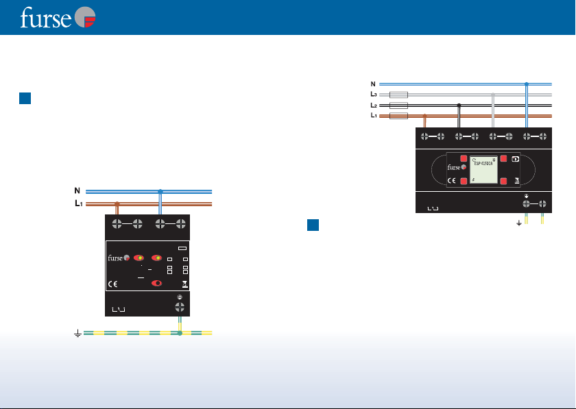
5
Parallel connection
ESP D1 protectors can be connected in parallel with the
supply to be protected, or connected in-line (series), for
power supplies ≤125A (see 6).
For parallel connection, the connecting leads do not carry
the load current of the supply, only the current associated
with suppressing the transient overvoltage.
I
T1
imp
I
20kA
n
T2 C
I
max
U
oc
125 AgL
4kA
B
40kA
DT3
6kV
Figure 6
- Parallel
connection
for single
phase supplies.
LL1N1N
PATENT
APPLIED
ESP 240D1
FOR
STATUS INDICATION
L N
GREEN
U
280V 47-63H
zac
c
GREEN & RED REDUCED
EN/IEC 61643
RED NO PROTECTION
WARNING: If lit /
flashing disconnect
unit & check Neutral
to Earth voltage
STATUS
11
14
12
FULL PROTECTION
PROTECTION
(replace unit)
!
Figures 6 & 7 show connection diagrams for single
phase and three phase star power supplies.
Connecting leads to the unit need to be kept short in
order to minimise additive inductive voltages.
Figure 7 - Parallel
connection for
three phase
star (4 wire and
earth) supplies.
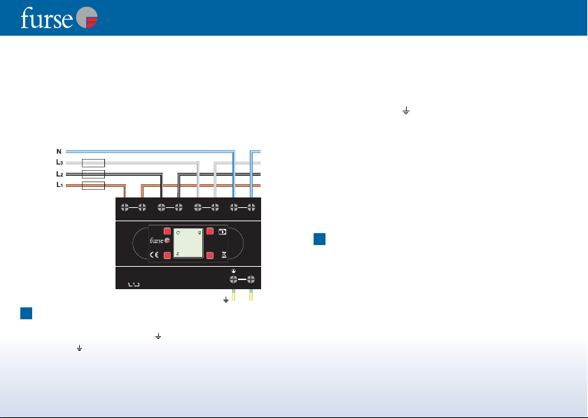
6
Series connection
LL' L2 L2' L3 L3' NN'
PATENT
APPLIED
FOR
EN/IEC 61643
STATUS
11
14
12
Enhanced
URGE
Mains
Protector
TIV
The twin terminal design of ESP D1 units enables
installation in-line (series) with the power supply
(for power supplies ≤125A). The supply cables should be
suitably rated for the specific load current. The terminals of
the ESP unit can receive up to 35 mm2stranded cable.
Any type of protector installed in parallel (shunt) with the
supply will have additive inductive voltage on the connecting
leads. This resultant voltage let-through the protector is
hence seen by the equipment to be protected (see 5
and 12). Series installation eliminates the additive voltage
associated with connecting leads on parallel installations.
PE
Page |11Page |10
Page 7
Installation instructions for mains wire-in protectors
R
SURG
P
N
A
E
Ensure the power supply does not exceed 125A
for series installations. The connecting leads to
phase/live terminals should be suitably fused (125A
maximum) ensuring full discrimination with the
immediate upstream supply fuse.
Figure 8 shows the connection diagram for three phase
star power supplies.
Figure 8 - Series
connection for
three phase star
(4 wire and
earth) supplies.
7
Connection to phase, neutral and earth
LL'L2 L2' L3 L3' NN'
PATENT
APPLIED
FOR
ESP 415D1
ROTECTIO
EN/IEC 61643
CTIV
STATUS
11
14
12
Connections are made to each supply conductor including
earth. Terminals marked L, N, (single phase units) or L1,
L2, L3, N, (three phase units) must be connected to
phase/live, neutral and earth respectively.
Under no circumstances must the ESP unit be installed
without connection to its neutral.
Where no neutral is present (eg delta supplies) the neutral (N)
terminal on the ESP unit must be connected to earth in
addition to the earth ( ) terminal. This will result in a greatly
increased earth leakage current.
On some delta supplies the voltage between phase and
earth/neutral may exceed the rating of the ESP unit.
Consequently, the supply’s phase to earth voltage must be
checked before installing the ESP unit.
We recommend that you consult Furse ESP before
installing ESP units on delta supplies.
Enhanced
E
Mains
Protector
PE
8
Connection point
(a) Protecting supplies feeding equipment in the building
The ESP unit is typically connected to the power supply
at a power distribution board/panel, either:
(i) on the load side of the incoming isolator (Figure 9).
(ii) on the closest available outgoing way to the incoming
supply (ie the incoming isolator).
Page |13Page |12
Page 8

Installation instructions for mains wire-in protectors
PE
Enhanced
Mains
Protector
EN/IEC 61643
PATENT
APPLIED
FOR
LL'L2 L2' L3 L3' NN'
11
14
12
STATUS
Figure 9 - ESP unit mounted
within a distribution board
connected to the incoming
supply on the load side
(ie downstream) of the
isolator. (Note the additional
earth bond to the metalwork
PE
Mains
Protector
Enhanced
FOR
EN/IEC 61643
PATENT
APPLIED
12
11
14
STATUS
LL'L2 L2' L3 L3' NN'
of the distribution board.)
This technique is
explained in 12(iii)
The ESP unit can be connected via one of the distribution
board’s outgoing fuseways or circuit breakers. Ideally, the
ESP unit should be connected to the outgoing way
which is nearest to the incoming supply (or isolator).
See Figure 10.
On small, compact, metal cased distribution boards, (such
as small MCB boards) the first way is preferable, although
any outgoing way is suitable.
On a large board such as a cubicle switchboard, it is better to
install the protector on the load side of the incoming isolator
Page |14
(eg in the metering section). Fitting the protector in any other
position could affect the protector’s performance.
(iii) directly to the busbars via suitable HRC fuses, switch
fuses or MCCBs - see Section 10.
Figure 10 - Three phase ESP protector connected to the nearest
available outgoing (MCB) way to the incoming supply. The MCB
also provides the means of isolation. Since there is insufficient
space within the distribution board the ESP unit has been
mounted within a separate enclosure, directly alongside the board.
Note the double connection to earth, in order to compensate for
the long connecting leads. (See 12 Length of connecting leads this also gives an alternative technique in 12(iii).)
Page |15
Page 9

(b) Protecting supplies going out of the building
The connection methods 8a (i to iii) are not suitable for
protecting a power distribution board which provides a
supply to outside the building - either to a separate building
or some other external load (eg site lighting).
To protect the equipment inside the building, from transient
overvoltages entering the board on the outgoing feed,
protection should be installed close to the external load.
See Figure 11.
Figure 11 Connection for
supplies continuing
external to the
building.
Installation instructions for mains wire-in protectors
9
Isolation
It is good practice to be able to isolate or disconnect the
ESP unit from the supply. The supply to the entire
distribution board should not be switched off on many
computer power supplies and other critical loads.
The means of isolation should therefore be installed in the
connection to the ESP unit. Figures 12 & 13 show example
connection schematics. Where it is also necessary to fuse
the connection to the ESP unit (see 10 - Fuse connecting
leads) this can be achieved through use of a switchfuse,
MCCB or type ’C’ MCB.
Figure 12 - ESP unit
installed on incoming side
of distribution board.
Page |16
PE
Mains
Protector
Enhanced
FOR
EN/IEC 61643
PATENT
APPLIED
12
11
14
STATUS
LL'L2 L2' L3 L3' NN'
Incoming
supply
fused F
S
HRC switch fuse or MCCB
F
, where F
SPD
< 0.5 FS
SPD
LL' L2 L2' L3 L3' NN'
PATENT
APPLIED
FOR
EN/IEC 61643
STATUS
11
14
12
Enhanced
Mains
Protector
PE
Page |17
Page 10

Installation instructions for mains wire-in protectors
L N
T2 C
T1
I
imp
4kA
I
n
20kA
I
max
oc
40kA
U
6kV
c
zac
U
280V 47-63H
B
DT3
125 AgL
!
GREEN
FULL PROTECTION
GREEN & RED REDUCED
PROTECTION
(replace unit)
RED NO PROTECTION
WARNING: If lit /
flashing disconnect
unit & check Neutral
to Earth voltage
EN/IEC 61643
PATENT
APPLIED
FOR
STATUS INDICATION
ESP 240D1
LL1N1N
11
14
12
STATUS
Figure 13 - Installation of
ESP unit on first outgoing
way of distribution
board, nearest to the
incoming supply.
Incoming
supply
fused F
S
10
Fuse connecting leads
HRC switch fuse or MCCB
, where F
SPD
< 0.5 FS
F
SPD
The connecting leads to the phase/live terminals of the
ESP units should be fused.
This is to protect the connecting leads in the event of a
short circuit.
The fuse to the ESP unit (F
upstream supply fuse FSby a sufficient enough factor to
ensure fuse discrimination. As a general guide a factor of
at least 2 could be used (F
maximum fuse to the ESP unit required is 125 amps
(if the supply fuse is 250 amps or greater).
) should be lower than the
SPD
≤ 0.5 FS), where the
SPD
Refer to the fuse manufacturer’s operating characteristics
to ensure discrimination, particularly where an installation
PE
Mains
Protector
Enhanced
includes a mixture of types of fuse, or of fuses and
circuit breakers.
Live/phase connecting leads can be fused by either:
(a) installing high rupture capacity (HRC) fuses or switch
FOR
EN/IEC 61643
PATENT
APPLIED
12
11
14
STATUS
LL'L2 L2' L3 L3' NN'
fuses in the connecting leads at the supply end of the
lead (See Figure 14), or
(b) installing up to a
125 amp circuit breaker
(MCCB or type ’C’ MCB).
Where the ESP unit is
installed via an outgoing
way (8b earlier) this
should incorporate
up to a 125 amp HRC
fuse or circuit breaker.
Figure 14 - Busbar
mounted HRC fuse at
the end of the live
connecting lead.
Page |19Page |18
Page 11

Installation instructions for mains wire-in protectors
11
Size of connecting leads
For parallel connection, the connecting leads between the
terminals of the ESP unit and the power supply should be
10 mm2multi stranded conductor (copper). If required,
the terminals on the ESP unit will accept connecting leads
of up to 35 mm2. (For series connection, see 6).
12
Length of connecting leads – parallel connection
For ESP units installed in parallel, the connecting leads
should be kept as short as possible and ideally should
not exceed 25 cm (10 inches) from the busbars to the
unit’s terminals.
ESP units can be mounted upside down or on their
side if this facilitates shorter connecting leads.
ESP D1/LCD units include a rotating display function for
improved legibility when units are mounted sideways or
upside down (see page 31).
ESP protectors with remote display units (D1R variants)
allow the protector to be mounted with short connecting
leads whilst allowing the display to be positioned
independently (eg conveniently on the front of the panel).
The display is connected to the protector via the supplied
1 m cable (4 m cable optional). The remote display cut-out
template, which can be found at the back of these
instructions, conforms to the standard DIN 72x36 format.
WARNING: The longer the connecting leads (between
the mains cable or busbars and the terminals of the ESP
unit), the greater the voltage let-through the protector.
If the resultant let-through voltage is higher than the
susceptibility level of the equipment to be protected,
damage will result.
Connecting leads up to 50 cm (20 inches) can be
used when:
(i) Two sets of 6 mm
2
cables are used (ie two sets of live,
neutral and earth conductors). Each set of conductors is
tightly bound together, using Ty-Raps®, tape or
spiral wrap.
This should be done for the entire length of the cable or
as far as is possible. The two sets of bound conductors
should be separated in their routeing. Ideally a distance
of 10 cm (4 inches) should be maintained between the
two sets of conductors as far as possible. See Figure 15.
(ii) Alternatively, if only one conductor needs to be longer
than 25 cm then use a pair of separated (as above)
conductors to make that connection. See Figure 10.
(iii) For metal distribution boards, if only the earth
connection needs to be longer than 25 cm, the
following procedure is suggested (see Figure 10):
Page |21Page |20
Page 12

(a) Using 6 mm2cable make one connection from the
ESP unit to the earth bar.
(b) A second short and direct connection, again using
2
6 mm
cable, should be taken from the ESP unit
to the metalwork of the distribution board.
(c) Bond the earth bar to the metalwork of the
distribution board.
The techniques outlined above (i-iii) are designed to
minimise the inductance associated with the
connecting leads.
Figure 15 - For
connecting leads
of up to 50 cm
use two sets of
conductors (L1, L2,
L3, N, ). Each set
of conductors has
been tightly bound
and separated
in their routeing.
Installation instructions for mains wire-in protectors
13
Length of connecting leads – series connection
For ESP units installed in series (for power supplies ≤125A),
the connecting lead to earth needs be kept as short as
possible and ideally should not exceed 25 cm (10 inches)
from the busbars to the unit’s terminals.
ESP units can be mounted upside down or on their
side if this facilitates shorter connecting leads.
Three phase ESP D1 protectors are available with rotating
LCD display (ESP D1/LCD variants) and remote mounting
display (ESP D1R and ESP D1R/LCD variants) for optimum
positioning of the unit whilst enabling easy ongoing
status checking.
14
Bind connecting leads – parallel connection
Connecting leads should be tightly bound together using
Ty-Raps®, tape or spiral wrap. This should be done for the
entire length of the cable or as far as is possible.
See Figure 15.
Page |23Page |22
Page 13

Installation instructions for mains wire-in protectors
Installation check (LED units)
The ESP unit should now be correctly installed. Switch the
power supply on. Check that a green LED per phase and
neutral is lit. See Figure 16. The unit is now fully operational.
Watch the WARNING light for 30 seconds. If it is flashing or lit
there is a problem with your installation (see opposite).
LL' L2 L2' L3 L3' NN'
PATENT
APPLIED
FOR
U
280V 47-63H
c
EN/IEC 61643
STATUS
14
zac
11
12
ESP 415D1
STATUS INDICATION
L1
GREEN FULL PROTECTION
GREEN & RED REDUCED PROTECTION
RED NO PROTECTION
(replace unit)
WARNING: If lit / flashing
N
disconnect unit & check
Neutral to Earth voltage
L3L2
!
Figure 16 - Status indication lights showing full protection on all
phases and neutral. On D1R units, status indication is shown on
the remote display unit.
I
4kA
T1
imp
I
20kA
n
T2 C
I
40kA
max
U
6kV
oc
125 AgL
B
DT3
PE
Neutral-earth warning light (LED units)
If the WARNING light is illuminated there is an excessive
voltage present between neutral and earth.
The WARNING light should never be illuminated.
(a) Illumination at time of installation
If the WARNING light flashes as soon as the mains supply
to the ESP unit is turned on, one of the phase/live cables
may have been connected to neutral and the neutral to
phase/live. Isolate or disconnect the ESP unit
immediately. Check the phase/live and neutral
connections and if a mistake has been made, correct it.
If all the phase/live and neutral connections are correct,
there is a fault with the mains supply (see (b) - below).
Note: The ESP unit may have suffered damage
- check the status indication (see page 26).
(b) Illumination at any time
The WARNING light will flash when the neutral to earth
voltage exceeds 30 volts. The faster the flashing, the
higher the voltage between neutral and earth (at very
high voltages the WARNING light may appear to be
permanently illuminated). Disconnect the ESP
protector immediately and check the mains supply.
The ESP protector should not be reconnected until the
cause of the fault has been identified and rectified.
Note: The ESP unit may have suffered damage
- check the status indication (see page 26).
Page |25Page |24
Page 14
Installation instructions for mains wire-in protectors
N
3
!
Status indication (LED units)
ESP units give a continuous visual display of their status. They
have a two colour indicator light for each phase and neutral:
Green only = Full protection, power on.
Green + Red = WARNING. Reduced protection,
Red only = NO PROTECTION. Replace ESP unit immediately.
No lights = No power connection or system fault.
replace unit as soon as possible.
Check external fuses and connections.
Status indication (LCD units)
Following installation, switch the power supply on.
The LCD display will illuminate for 15 seconds and show
the introductory status screen for correct performance.
The introductory screen alternates to show protector status
every 2-3 seconds (ESP 415D1R example shown).
Introductory screen Protector status
Normal
operation:
P 415D1R
URGE
PROTECTIO
TIVE
Page |26
LY ACTIVE
The unit is now fully operational. These display messages will
be visible and alternate at all times the protector is connected
and is functioning correctly.
Where a fault or power supply issue is detected by the
protector, the LCD message will change, the backlight will
flash, and the protector will sound an alert. Several types of
fault will trigger a response from the ESP protector.
Line fault – no connection or system fault
Live (including neutral) connections will register a ‘’ if
protected and functioning properly. If any of the live
connections is lost, the LCD screen will query this with ‘OFF?’.
The example below shows a power supply issue for L1.
Warning screen Alternates with
L1 Fault
(no power)
[BACK-LIT
DISPLAY
ON - FAST
FLASHING]
[AUDIBLE
ALERT]
WARNING
ISCONNECT
ND
NVESTIGATE
0V
RLY DISABLED
30V
Disconnect the unit and check external fuses and connections.
Page |27
Page 15

Installation instructions for mains wire-in protectors
T
30
ON
T
3
30
!
Line fault – protection impaired
Live connections (including neutral) will register a ‘’ if
protected and functioning properly. Where protection to a live
connection is impaired, the LCD screen will query this with ‘’,
the backlight will flash and an audible alert will sound.
The examples below show L1 has reduced or no protection.
Warning screen Alternates with
L1 Fault
(reduced
protection)
[BACK-LIT
DISPLAY
ON - SLOW
FLASHING]
[AUDIBLE
ALERT]
L1 Fault (no
protection)
[BACK-LIT
DISPLAY
ON - FAST
FLASHING]
[AUDIBLE
ALERT]
Reduced protection – replace unit as soon as possible.
No protection – replace unit immediately.
Page |28
EDUCED
PROTECTION
REPLACE
UNI
ROTECTI
EPLACE
NI
LY DISABLED
1
N
LY DISABLED
Neutral-earth warning
The Neutral-earth warning screen will display if there is an
excessive voltage present between neutral and earth, or if
there is no protection on the N-E connection. The backlight will
flash and an audible alert will sound.
Warning screen Alternates with
N – E Fault
(over 30
volts
V
=
=
0V
detected)
[BACK-LIT
DISPLAY
ON - FAST
FLASHING]
[AUDIBLE
ALERT]
(a) Illumination at time of installation
If the WARNING message and backlight flashes as soon as the
mains supply to the ESP unit is turned on, one of the phase/live
cables may have been connected to neutral and the neutral to
phase/live. Isolate or disconnect the ESP unit immediately.
WARNING
ISCONNECT
ND
NVESTIGATE
V
Page |29
Page 16

Installation instructions for mains wire-in protectors
R
E
E
GE
ON
AC
E
90
0
Check the phase/live and neutral connections and if a mistake
has been made, correct it. If all the phase/live and neutral
connections are correct, there is a fault with the mains supply
(see (b) - below).
Note: The ESP unit may have suffered damage - check the
status indication.
(b) Illumination at any time
The WARNING message and backlight will flash when the
neutral to earth voltage exceeds 30 volts.
Disconnect the ESP protector immediately and check the
mains supply.
The ESP protector should not be reconnected until the cause of
the fault has been identified and rectified. Note: The ESP unit
may have suffered damage - check the status indication.
LCD display settings
The LCD display has enhanced functionality to improve
legibility of status information. The display functions are
controlled through the 4 buttons, located near each corner of
the screen, where control icons are displayed. Display functions
include:
Page |30
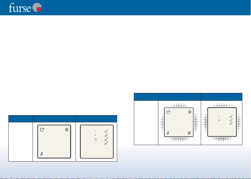
Rotate display function
For rotate display, start with introductory screen
(shown below)
PATENT
APPLIED
FOR
EN/IEC 61643
PATENT
APPLIED
FOR
EN/IEC 61643
ESP 415D1R
PROTECTI
FOR
PATENT
APPLIED
Mains
Enhanced
UR
TIV
27
Protector
EN/IEC 61643
ESP 415D1
SURG
ROTECTION
ACTIV
ELECT
REEN ANGLE
Enhanced
Mains
Protector
Enhanced
Mains
Protector
Press and hold the
rotate display button
for a couple of seconds
to call up the screen
angle selection screen.
The display rotates
clockwise in 90° steps.
By selecting 90, the
screen rotates 90°
clockwise as shown left,
enabling the D1/LCD
protector or D1R/LCD
remote display to be
positioned vertically.
Page |31
Page 17

Installation instructions for mains wire-in protectors
R
E
E
AC
Enhanced
Mains
Protector
EN/IEC 61643
PATENT
APPLIED
FOR
R
E
E
Enhanced
Mains
Protector
EN/IEC 61643
PATENT
APPLIED
FOR
2
2. BUILD
2. BU
© T&B 2
Enhanced
Mains
Protector
EN/IEC 61643
PATENT
APPLIED
FOR
E
00
Enhanced
Mains
Protector
EN/IEC 61643
PATENT
APPLIED
FOR
E
3309
Enhanced
Mains
Protector
EN/IEC 61643
PATENT
APPLIED
FOR
ON
CE
Page |32
Activate backlight
PATENT
APPLIED
FOR
EN/IEC 61643
PATENT
APPLIED
FOR
EN/IEC 61643
ESP 415D1
SURG
ROTECTION
ACTIV
SP 415D1R
URGE
PROTECTION
TIVE
Silence buzzer
EDUCED
PROTECTI
REPLA
Press and hold the
activate backlight button
Enhanced
for a couple of seconds to
Mains
Protector
illuminate the display
screen.
The backlight will
activate for approximately
15 seconds.
Enhanced
Mains
Protector
ESP D1/LCD and D1R/LCD
protectors include a
buzzer alert which activates
when a unit has reduced or
no protection, or when
there is a supply fault (phase
loss, excessive N-E voltage).
To deactivate the buzzer,
firmly press the silence
buzzer button (buzzer
deactivates for 1 hour).
Protector information
ESP 415D1
SURG
ROTECTION
ACTIV
MENU
. VERSION
1. VERSION
OFTWAR
ER 2.
2. BUILD (Format: wwyy)
BUILD DAT
For Protector Information,
start with the introductory
screen (shown left). Press
and hold the information
button for a couple of
seconds to call up the
information menu.
The information menu
provides a link to the
software version (1)
and build date of the
protector (2).
Press and hold the top left
button to select software
version (1. VERSION).
Press and hold the top right
button to review protector’
build date (2. BUILD).
To exit the information
screens and return to the
introductory screen, press
and hold the bottom right
button, (EXIT).
Page |33
Page 18

Installation instructions for mains wire-in protectors
Remote indication
A remote indication of the reduced protection state is provided
for linking the protector to a building management system,
remote telemetry, PLC or directly to an indication light or buzzer.
The unit has both a normally open and a normally closed volt
free contact, powered by an ‘active‘ relay.
The terminal for the volt free contact accepts 1.5 mm
and is located on the bottom of the ESP unit. It has three
terminals, marked:
14 = NO = Normally Open
12 = NC = Normally Closed
11 = C = Common
The normally open (NO) contact is open when the ESP unit is
healthy and power is present. The normally closed (NC) contact
is closed when the unit is healthy and power is present.
As well as providing warning of the reduced protection state,
the normally closed volt free contact can also be used to signal
power loss on one or more phases, eliminating the need for
special relays. See Figure 17.
The ESP units remote indication is rated at 1 amp, 250V AC.
A minimum load of 10mA, 5V DC is required to ensure reliable
contact operation.
Page |34
2
cable
Unit Healthy
Reduced or
No protection
NO NC NO NC
OPEN
Power Present
Power Absent
Figure 17. Operation of normally closed (NC) and normally
open (NO) volt free contact.
While the relay is active and functioning correctly the LCD display
will show the 'normal operation' screens - RLY ACTIVE.
CLOSED
CLOSED
CLOSED
OPEN CLOSED
OPEN
OPEN
Maintenance
Maintenance should be conducted at least once a year and
also following lightning activity. Visually check:
(i) Visual status indication lights/LCD display
(see Status indication for interpretation).
(ii) Condition of connecting leads and terminations.
Page |35
Page 19

Installation instructions for mains wire-in protectors
Application notes
1
ESP coordination
ESP D1, D1R, D1/LCD and D1R/LCD units are designed to
fully coordinate with ESP units of equivalent system
voltage on the same installation.
For example the ESP 415 M2 located at the main
distribution panel would coordinate effectively with
the ESP 415 D1 unit typically located at sub-distribution
panels. No additional de-coupling elements such as
inductors are needed to ensure ESP units achieve
coordination.
Always ensure ESP units are used on the same installation
to ensure coordination. Mixing ESP units with alternative
manufacturers’ units could result in damage to both
protection units and connected equipment through
poor coordination.
2
RCD units
ESP units should ideally be installed before (or upstream of)
residual current devices (RCDs) and not on the load side.
ESP units should only be installed on the load side of the
RCDs if the load in question is external to the building.
Page |36
This should help to reduce any spurious tripping of such
devices due to transient overvoltages. Special transient
hardened RCDs (type ’S’) can be obtained from a number
of manufacturers.
3
Insulation tests (flash testing)
The ESP unit should be fully disconnected from the circuit
before testing. Otherwise the ESP unit will treat the
insulation test as a transient overvoltage and control the
voltage to a low level - thereby defeating the object of
the test.
4
Duplex configuration
For systems demanding extremely high reliability ESP units
can be connected in duplex format. The use of two units
will achieve an improvement in performance and increased
lifetime over a single ESP unit at high discharge current
levels.
Each unit should have its own (separate) wiring and
its own isolation.
If possible the two units should be connected to the
power supply a short distance apart either:
(a) onto the first two outgoing ways
(b) up to a metre apart on the incoming power supply
Page |37
Page 20

5
33mm (+0.6)
68mm (+0.7)
DIN 72x36
as per IEC 61554
Installing three phase units on single phase supplies
If a three phase unit is installed on a single phase mains
supply (or a supply in which one or two phases are not in
use), the ESP units spare (or unused) live terminal(s) should
be connected to live, otherwise its indication lights and
volt free contact will not work correctly.
The preferred approach is to take a connecting lead from
each spare terminal to the supply live. However, it is also
possible to connect the ESP units spare terminal(s) to
whichever live terminal is in use at the unit.
6
Thomas & Betts Limited
Furse, Wilford Road, Nottingham
NG2 1EB United Kingdom
Tel: +44 (0)115 964 3700 Fax: +44 (0)115 986 0538
www.furse.com
Use of powered screwdrivers
The use of powered screwdrivers is not recommended
unless measures are taken to ensure screws are tightened
correctly and not damaged (maximum torque value
is 4.5 Nm for these terminals).
Remote display cut-out template
Page |38
Page|39
Page 21

Thank you for reading this data sheet.
For pricing or for further information, please contact us at our UK Office, using the details
below.
UK Office
Keison Products,
P.O. Box 2124, Chelmsford, Essex, CM1 3UP, England.
Tel: +44 (0)330 088 0560
Fax: +44 (0)1245 808399
Email: sales@keison.co.uk
Please note - Product designs and specifications are subject to change without notice. The user is responsible for determining the
suitability of this product.
 Loading...