

Thomas & Betts elastimold 375LR, elastimold 376LR Installation & Operating Instructions Manual
Page 1
IS---0359
IS---375/376LR
March 2010
Page 1 of 4
Installation & Operating Instructions
375LR (without test point)
376LR (with test point)
Loadbreak Elbow Connectors
CONTENTS: Elbow Connector Housing, Compression Lug, Probe, Probe Wrench, Lubricant (Do Not Substitute),
Installation/Operating Instructions.
The 375LR (without test point) and 376LR (with test point) aredesigned to terminate UD cable having concentric neutral and
extruded insulation shielding. The elbow provides an operating interface forconnecting to an Elastimold 35kV class (21.1kV
phase--- to---ground and 36.6kV phase ---to --- phase) 200 ampere loadbreak bushing or accessory device with fault close
rating of 10,000 amperes RMS symmetrical. When other types of UD cable are to be terminated an appropriate Elastimold
cable shield or grounding device must be used.
DANGER
All apparatus must be de--energized during installation
or removal of part(s) except for test point caps and
indicators that can be installed and operated
energized.
After installation loadbreak products can be operated
energized per operating instructions. All deadbreak
connectors must be de--energized before operating.
All apparatus must be installed and operated in
accordance with individual user, local, and national
work rules. These instructions do not attempt to
provide for every possible contingency.
Do not touch or move energized products.
“Loadbreak connectors must be operated with a full
insulated “hotstick” type live--line tool.” Consult the
company’s safe work practices for the required
live--line tool length.
FOR MORE INFORMATION ON PARTS, INSTALLATION RATINGS AND COMPATIBILITY, CALL THE NEAREST ELASTIMOLD OFFICE.
Excess distortion of the assembled product may result
in its failure.
Inspect parts for damage, rating and compatibility with
mating parts.
This product should be installed only by competent
personnel trained in good safety practices involving
high voltage electrical equipment. These instructions
are not intended as asubstitute foradequate training or
experience in such safety practices.
Failure to follow these instructions will result in
damage to the product and serious or fatal injury.
If this product is supplied with a protective shipping
cover(s), remove this shipping cover(s) and replace
with the appropriate HV insulated cap(s) or
connector(s) before submerging or energizing the
circuit.
IMPORTANT
1. Check contents of package to ensure they are complete
and undamaged.
2. Check all components to ensure proper fit with cable
and/or mating products.
3. Check threadsby threading probe into compression lug.
If resistance is encountered priorto fullassembly, check
for damage and replace damaged component.
4. Read entire installation instructions before starting.
5. Have all required tools at hand and maintain cleanliness
throughout the procedure.
CAUTION: Lubricate test point cap and assemble tightly.
IS---0359
IS---375/376LR
March 2010
Printed in U.S.A.
8155 T&B Boulevard, Memphis, Tennessee 38125
(800) 888--0211 Fax: (800) 888--0690
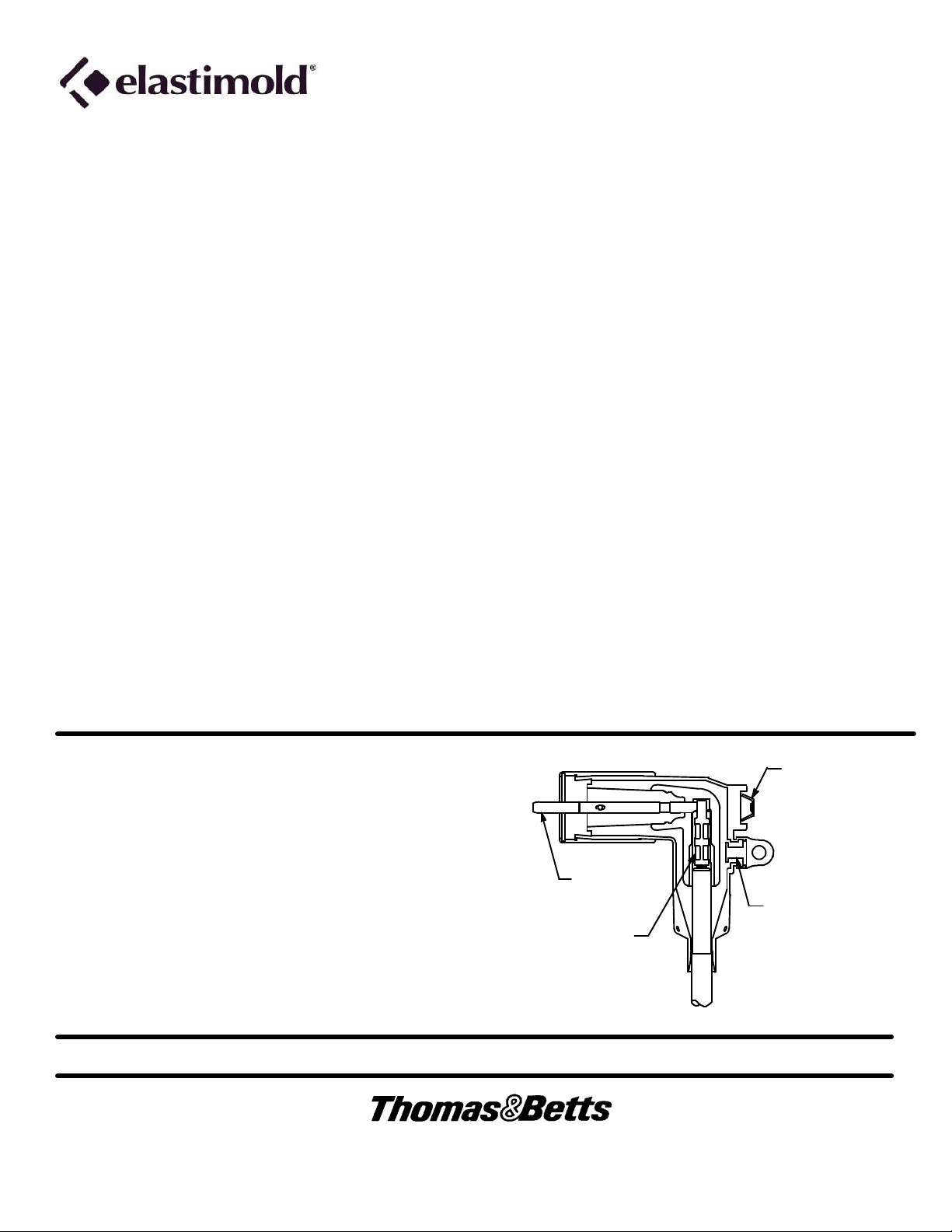
Operating
Eye
Probe
Test Point
(376LR Only)
Compression
Lug
ASSEMBLED ELBOW
Page 2
IS---0359
March 2010
Page 2 of 4
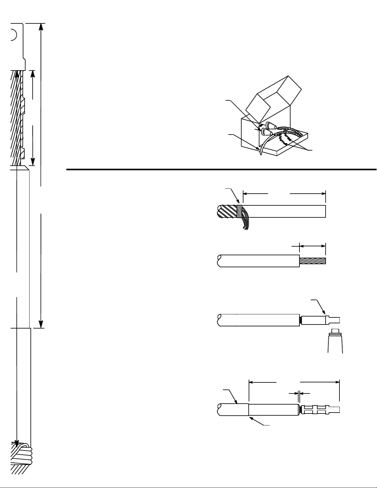
STEP 1 CABLE TRAINING
A. Train cable as shown to ease
operation.
B. Cut excess cable squarely at center
2--- 1/8”
CABLE CUT BACK TEMPLATE
line of bushing.
Center
Lines
Excess
Cable
20” min.
beyond end
of cable
Pad Mount Transformer
STEP 2 CABLE PREPARATION
6--- 7/8”
8--- 1/2”
(Use cable cut back template for
dimensional guide.)
A. Unwrap and bind concentric neutral
wires 8--- 1/2” back from end of cable.
B. Remove shield and insulation from
the cable end. Cut squarely taking
care not to nick conductor.
C. Wire brush bare aluminum conductors
and immediately install compression
lug. Rotate to spread inhibitor.
Position compression lug so the
CONTACTTHREADED HOLE ALIGNS
WITHTHE BUSHING BORE. (Refer to
crimp chart packaged with compression
lug for recommended crimp tool
information.) Start crimp at the crimp
line mark. Rotate 180_ each
successive crimp. Carefully wipe
excessive inhibitor from the outside
of the lug and cable.
D. Remove insulation shield as shown.
Bevel insulation end 1/8” max.
E. Thoroughly clean insulation to
remove all traces of conductive
residue.
Bind
8---1/2”
2---1/8”
Start Crimp Here
Align lug thread
to bushing bore.
Insulation
Shield
6---7/8”
1/8” Max.
Bevel
Insulation
Straight, Smooth & Squared
Do not cut or nick insulation.
Page 3

STEP 3 ELBOW ASSEMBLY
A. Lubricate the cable insulation and inside the elbow
housing with the lubricant supplied. DO NOT
SUBSTITUTE. Other lubricants may be harmful tothis
product or its mating product(s). Keep insulation
clean of dirt and grime.
B. Slide the elbow connector onto the cable with a back
and forth twisting motion. Wipe off all excess grease.
C. Align elbow with compression lug’s threaded hole.
D. Thread probe into lug by hand, taking care not to
cross---thread. The probe must turn freely for
approximately four turns before becoming snug.
Tighten with wrench until wrench bends.
Wrench Hole
Probe
Wrench
IS---0359
March 2010
Page 3 of 4
Twist
Lubricate
Align
STEP 4 CONCENTRIC NEUTRAL CONNECTION
A. Using aseparate copperwire (No. 14AWG / 2.5mm)or
equivalent, insert one end through the grounding eye
on the elbow. Twist tight taking care not to damage the
eye.
B. Twist all neutral wires and connect to ground using
appropriate connector. Provide adequate slack in
wires for elbow operation.
Provide Slack
for Operation
Grounding
Eye
STEP 5 CONNECT ELBOW AND BUSHING PLUG
A. Lubricate the receptacle portion of the elbow connector and the mating bushing with the lubricant supplied. LUBRICATE
ONLY IF THE TRANSFORMER AND ELBOW ARE KNOWN TO BE DE---ENERGIZED.
B. Operate per following instructions. DO NOT OPERATE BY HAND.
Lubricate only if known to be de ---energized
Hotstick
Page 4

IS---0359
March 2010
Page 4 of 4
OPERATING INSTRUCTIONS
Before Loadmake or Loadbreak Operation:
Area must be clear of obstructions or contaminants that would interfere with the operation of the connector. This position
should allowyou to establish firmfooting and enable you tograsp thehotstick tool securely, maintaining positive control over
the movement of the loadbreak connector before, during and directly after the operating sequence. A minimum hotstick
length of 8 ft. is recommended. Because of the control, speed and force requiredto engage or disengage the elbow, certain
operating positions are more advantageous than others. If there is some question as to proper operating position, it is
recommended that the connectors be operated de--- energized. Do not connect two different phases of a multiple---phase
system. Before closing a single---phase loop, make certain both ends of the loop are the same phase.
LOADMAKE OPERATION
Loadbreak connectors must be operated with a full insulated ”hotstick” type live--line tool. Consult the
company’s safe work practices for the required live--line tool length.
1. Area must be clear of obstructions or contaminants that would interfere with the operation of the connector.
2. In preparing bushing for elbow connector, remove insulated cap by attaching hotstick tool to the insulated cap pulling
eye, and following the instructions for this accessory, remove from bushing.
3. Securely fasten a hotstick to the loadbreak connector pulling eye.
4. After establishing firm footing and positive control of the elbow connector, withdraw the elbow from the accessory
device on the apparatus parking stand with a fast, straight, firm motion being careful not to place the elbow connector
near a ground plane.
Check appropriate accessory device operating instructions to be sure that the device is rated for energized operation.
5. Insert the probe tip approximately 2” into the bushing (at this point the contacts are approximately 4” apart).
DO NOT HOLD IN THIS POSITION BUT IMMEDIATELY PUSH THE ELBOW HOME WITH A FAST, FIRM, STRAIGHT
MOTION.
Apply sufficient force to engage the internal lock on the elbow connector and bushing interface.
Fault Close
1. It is not recommended that operations be made on known faults.
2. If a fault is experienced, both the elbow connector and the bushing must be replaced.
LOADBREAK OPERATION
1. Place desired accessory device on apparatus parking stand.
Refer to appropriate operating instructions for accessory device to be used. Be certain it is rated for energized operation.
2. Firmly tighten a hotstick to the loadbreak connector pulling eye.
3. Without exerting any pulling force, slightly rotate the connector clockwise in order to break surface friction prior to
disconnection.
4. Withdraw theconnector from the bushing with a fast, firm,straight motion, being carefulnot to place theconnector near
a ground plane.
5. Place connector on appropriate accessory device, following the operating instructions for that accessory.
VOLTAGE TEST
ELASTIMOLD connectorsequipped with anintegral capacitancetest point canbe used toestablish whetheror not the circuit is
energized. When using the test point, complete the following steps:
1. Remove test point cap with a hotstick. When removing cap, PEELOFF AT AN ANGLE rather than pulling directly in line
with the test point assembly.
2. WARNING: THE VOLTAGE TEST POINT IS A CAPACITANCE DEVICE, IT IS NOT DIRECTLY CONNECTED TO
THE CONDUCTOR. Do not use conventional voltage measuringequipment. Followthe manufacturer’s directions for the
meter that is used. Test with a suitable sensing device, made for use with separable connectors manufactured with
capacitive test points, to determine if cable is energized. Contamination, moisture, dirt, etc. around the test point or use
of the wrong measuring equipment can provide a false “no voltage” indication on an energized elbow. To prevent
serious or fatal injury treat the elbow as energized until the “no voltage” test point indication is confirmed by other means.
3. After voltage detection has been made, clean and lubricate the inside surface of the cap with silicone grease and
replace it on the test point.
8155 T&B Boulevard, Memphis, Tennessee 38125
(800) 888--0211 Fax: (800) 888--0690
 Loading...