

Page 1

IS---0271
IS---168DRG
March 2010
Page 1 of2
Operating Instructions
168DRG
Insulated Cap with Test Point & Ground Lead
CONTENTS: Insulated Cap with test point, Ground Lead, Lubricant, Operating Instructions
The 168DRG is designed for insulating, shielding and watersealing anyELASTIMOLD 15kV class (8.3kV phase--- to ---ground
and 14.4kV phase---to ---phase) loadbreak bushing interface.
DANGER
All apparatus must be de--energized during installation
or removal of part(s) except for test point caps and
indicators that can be installed and operated
energized.
After installation loadbreak products can be operated
energized per operating instructions. All deadbreak
connectors must be de--energized before operating.
All apparatus must be installed and operated in
accordance with individual user, local, and national
work rules. These instructions do not attempt to
provide for every possible contingency.
Do not touch or move energized products.
“Loadbreak connectors must be operated with a full
insulated “hotstick” type live--line tool.” Consult the
company’s safe work practices for the required
live--line tool length.
FOR MORE INFORMATION ON PARTS, INSTALLATION RATINGS AND COMPATIBILITY, CALL THE NEAREST ELASTIMOLD OFFICE.
Excess distortion of the assembled product may result
in its failure.
Inspect parts for damage, rating and compatibility with
mating parts.
This product should be installed only by competent
personnel trained in good safety practices involving
high voltage electrical equipment. These instructions
are not intended as a substitute for adequate training or
experience in such safety practices.
Failure to follow these instructions will result in
damage to the product and serious or fatal injury.
If this product is supplied with a protective shipping
cover(s), remove this shipping cover(s) and replace
with the appropriate HV insulated cap(s) or
connector(s) before submerging or energizing the
circuit.
IMPORTANT
1. Check contents of package to ensure they are complete
and undamaged.
2. Check all components to ensure proper fit with cable
and/or mating products.
3. Read entire installation instructions before starting.
4. Have all required tools at hand and maintain cleanliness
throughout the procedure.
STEP 1
Connect free end of electrostatic grounding wire to the system ground, leaving enough slack for hot---stick operation of the
insulated cap. CAUTION: The electrostatic grounding wire should be trained so as not to contact the bushing interface
during operation. WARNING: IF THE GROUND LEAD DISCONNECTS DURING OPERATION, DO NOT ATTEMPT TO
REATTACH WITHOUT FIRST PULLING INSULATED CAP OFF THE BUSHING WITH THE HOTSTICK.
Grounding Eye
To Ground
Protective Cover
IS---0271
IS---168DRG
March 2010
Printed in U.S.A.
8155 T&B Boulevard, Memphis, Tennessee 38125
(800) 888--0211 Fax: (800) 888--0690
Page 2
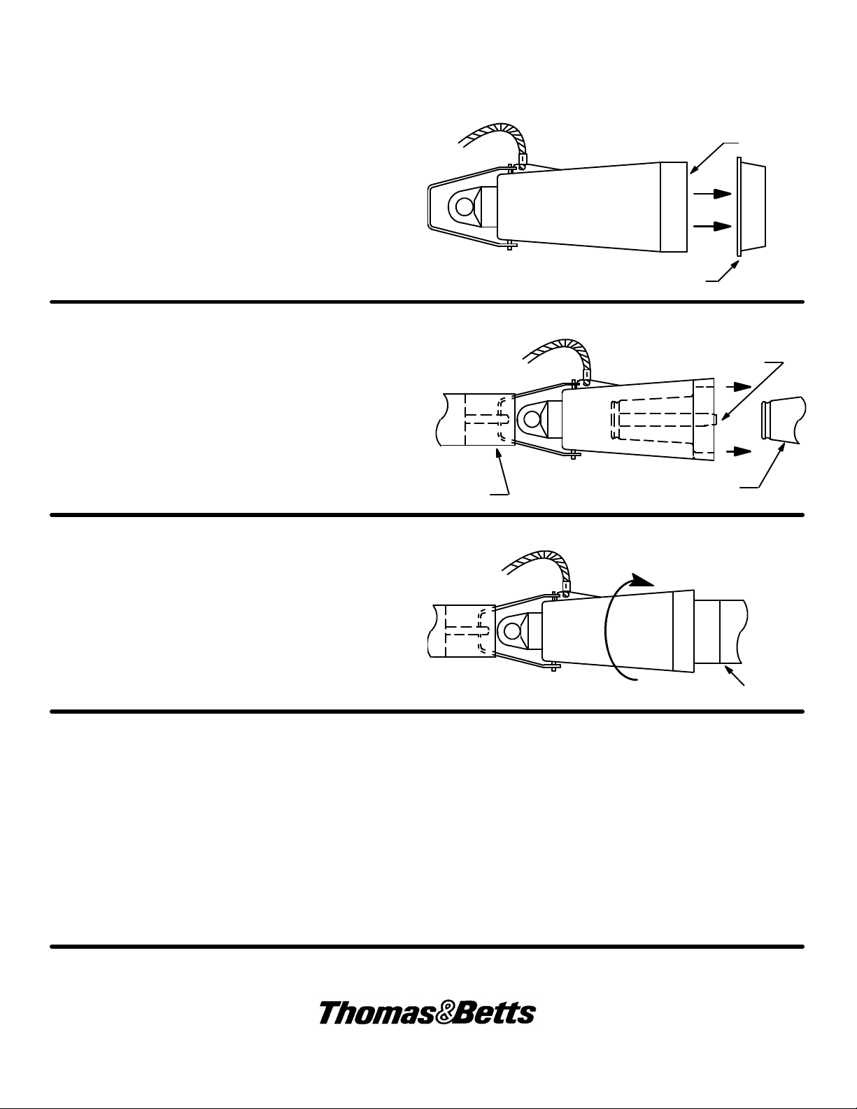
STEP 2
Remove protective cap from the insulated cap and
lubricate the receptacle’s internal mating surface. Use only
ELASTIMOLD approved lubricants. DO NOT
SUBSTITUTE. Other lubricants may be harmful to this
product and it mating products. Keep the internal mating
surface free from dirt and grime. Always replace protective
cover when not in use.
STEP 3
Firmly attach hotstick to the insulated cap pulling eye.
Insert the male contact of the insulated cap into the
loadbreak bushing, and push home with a fast, firm,
straight motion. Make certain it is fully mated, with the
locking ring seated. Detach hotstick from the insulated
cap.
IS---0271
March 2010
Page 2 of 2
Lubricate
Remove Protective Cover
Male
Contact
Hotstick
Bushing Interface
STEP 4
To remove. Attach hot--- stick to pulling eye. Before pulling
rotate insulated cap while in the mated position to break
surface friction. Pull receptacle off with a fast, firm, straight
motion to complete the operation. Remove electrostatic
grounding wire of the insulated cap from the system
ground. Replace protective cap on insulated cap to keepits
internal surface clean.
Rotate Slightly Before Pulling
VOLTAGE TEST
The ELASTIMOLD loadbreak elbow connector is equipped with an integral capacitance test point that can be used to
establish whether or not the circuit is energized. When using the test point, complete the following steps:
1. Remove test point cap with a hotstick. When removing cap, PEEL OFF AT AN ANGLE rather than pulling directlyin line
with the test point assembly.
2. WARNING: THE VOLTAGE TEST POINT IS A CAPACITANCE DEVICE, IT IS NOT DIRECTLY CONNECTED TO THE
CONDUCTOR. Do not use conventional voltage measuring equipment. Follow the manufacturer’s directions for the
meter that is used. Test with a suitable sensing device, made for use with separable connectors manufactured with
capacitive test points, to determine if cable is energized. Contamination, moisture, dirt, etc. around the test point or use
of the wrong measuring equipment can provide a false “no voltage” indication on an energized elbow. To prevent
serious or fatal injury treat the elbow as energized until the “no voltage” test point indication is confirmed by other means.
3. After voltage detection has been made, clean and lubricate the inside surface of the cap with silicone grease and
replace it on the test point.
Bushing
8155 T&B Boulevard, Memphis, Tennessee 38125
(800) 888--0211 Fax: (800) 888--0690
 Loading...