

Page 1
C E R T I F I E D
Applies to: Model Series DV
TABLE OF CONTENTS
INDOOR OR OUTDOOR, GAS,
DIRECT-FIRED, MAKEUP AIR/
HEATING SYSTEMS
(Specifications subject to change without notice.)
Operation/Maintenance/Service
Form RZ-NA 441-OMS
Page
MAINTENANCE
SECTION ...................... 2-4
Configuration ................................. 2
Maintenance Schedule ................... 2
1A. Blower Bearings .............................. 3
1B. Blower Belts ................................... 3
2. Filters ................................................. 3
3. Manifold Gas Pressure ...................... 3
4. Air Pressure ....................................... 4
5. Circuit Indicator Board (check lights) 4
6. Main Burner and Pilot Assembly ...... 4
OPERATION/SERVICE
SECTION ................... 5-15
Controls - Location ....................... 5
7. Electronic Circuit Board with
Diagnostic Lights.............................. 5
References: Installation Manual, Form RZ 441
Page
8. Temperature Limit Safety Controls... 5
•Manual Reset Limit Control ........... 5
•Emergency Cut Off Limit Control .. 6
9. Air Pressure Switches ........................ 6
•Low Air Flow Switch ...................... 6
•High Air Flow Switch ...................... 6
•Bypass Damper (Optional) Air
Flow Switches ................................ 6
10. Ignition System ................................ 6
11. Gas Train Including Direct-Fired
Burner, Gas Control Systems,
Manifold Arrangements and Gas
Pressure Switches ............................. 7
•Direct-Fired Burner ........................ 7
•Makeup Air Gas Control Systems .. 7
•Electronic Modulation Gas Control
Options AG30, AG31, AG32,
AG33, AG35, AG36 ...................... 7
•Electronic Modulation Gas Control
Option AG37 ................................. 7
12. Outside Air Ambient Cutoff ............ 8
13. Door Switch ..................................... 9
14. Inlet Air Controls ............................ 9
15. Dirty Filter Switch ......................... 10
16. Photoelectric Smoke Detector ....... 10
17. Firestat ........................................... 10
18. Freezestat ....................................... 10
19. Troubleshooting ............................. 11
Index ................................................... 12
Replacement Parts Manual, Form RZ 741
Page
•Manifold Arrangements ................. 8
•Gas Pressure Switches .................... 8
•Air Flow Dampers ........................... 9
•Damper Motor ................................. 9
•Potentiometer .................................. 9
•Pressure Null Switch ....................... 9
•Photohelic Pressure Switch ........... 10
Chart 1 - General Troubleshooting
Guide (Check the diagnostic lights on
the circuit board)
FOR YOUR SAFETY
WARNING: The use and storage of gasoline or
other flammable vapors and liquids in the vicinity
of this appliance is hazardous.
If you smell gas:
1. Open windows.
2. Don't touch electrical switches.
3. Extinguish any open flame.
4. Immediately call your gas supplier.
WARNING: Improper installation, adjustment,
alteration, service, or maintenance can cause
property damage, injury or death. Read the
installation, operation, and maintenance
instructions thoroughly before installing or
servicing this equipment.
KEEP THIS BOOKLET
FOR MAINTENANCE AND
SERVICE REFERENCE.
Operating/Maintenance/Service
Instructions
The information in this manual applies to Model Series DV, direct-fired heating/makeup air systems. As with any gas burning
equipment, regular maintenance procedures are required to ensure continued safety, reliability and efficiency of the installation.
If service is required, this system should be serviced only by a
qualified service person. Service information in this booklet is
intended as a guideline for a qualified gas-fired equipment service person.
Mfg No. 161442
Page 1
Page 2
DANGER: The gas burner in this direct gas-fired system is designed and equipped to provide safe and
economically controlled complete combustion. However, if the installation does not permit the burner to
receive the proper supply of combustion air, complete combustion may not occur. The result is incomplete
combustion which produces carbon monoxide, a poisonous gas that can cause death.
Always comply with the combustion air requirements in the installation codes and operating instructions.
The amount of air over the burner must be within the specified range. The burner profile plates are set at
the factory to match CFM requirements. Do not adjust the burner profile plates without contacting the
factory. FAILURE TO PROVIDE PROPER COMBUSTION AIR CAN RESULT IN A HEALTH
HAZARD WHICH CAN CAUSE PROPERTY DAMAGE, SERIOUS INJURY, AND/OR DEATH. Directfired installations should provide for air changes as required by the applicable installation codes.
Maintenance Section
This direct-fired makeup air system is designed to require only a minimum
amount of maintenance. Some maintenance procedures outlined in this Section
require inspection only and some require action. Frequency requirements of
each maintenance procedure are listed in the Maintenance Schedule. Depending
on the environment and the number of operating hours, more frequent inspection and/or cleaning may be required to certain components.
Although maintenance requirements are minimal, the routine maintenance procedures in this Section are necessary to ensure safe, reliable, and/or efficient
operation. The paragraphs which follow discuss the components and systems
that require routine inspection/maintenance. At the beginning of each paragraph,
there is a code indicating why that maintenance procedure is necessary. The
legend for that code is shown below.
Maintenance Codes
Reason for Maintenance
S = Safety (to avoid personal injury and/or property damage)
R = Continued Reliability
E = Efficient Operation
WARNING: Disconnect all power to the
system before doing any maintenance.
Failure to do so may cause electrical shock,
personal injury, or death.
Maintenance Schedule
See Chart
Quarterly
Semi-Annually
Annually
Lubricate bearings, Paragraph 1
Check the filters, Paragraph 2
Check air pressure sensing tubes,
Paragraph 4
Check blower belts, Paragraph 1
Verify gas pressures, Paragraph 3
Clean air pressure sensing tubes,
Paragraph 4
Check indicator lights, Paragraph
5
Check main burner and pilot
assembly, Paragraph 6
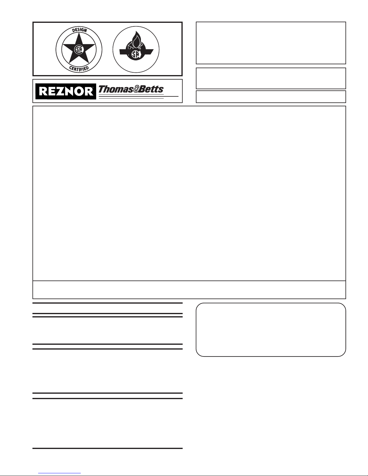
Discharge Air
Optional Return Air
Outside Air
Page 2
Figure 1 - System
Configuration
Blower
Section
Burner/Control Section
Location of Optional Filter
Cabinet (not shown)
Screened Inlet Base
Page 3
R
1. Drive Components
The blower, motor and drive components are located in the blower
cabinet at the top of the system. Systems with horizontal discharge
have a cabinet with eight removable door panels. Systems with vertical
discharge have a cabinet with six removable door panels. Remove the
panels required to access the components being serviced.
1A. Blower Bearings
All blowers are Class I with pillow block bearings. Clean the fitting and
add type NLG-2 or -2 standard grade grease. Add grease with a handgun
until a slight bead of grease forms at the seal. Be careful not to unseat
the seal by over lubricating.
NOTE: If unusual environmental conditions exist (temperatures below
o
F or above 200oF; moisture; or contaminants) more frequent lubri-
32
cation is required.
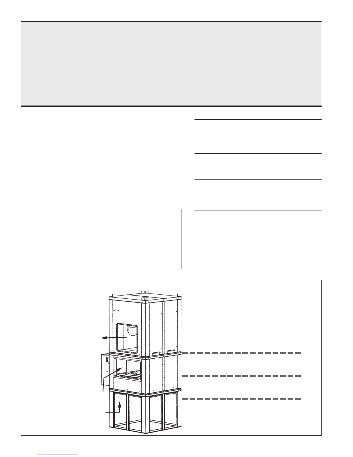
excessive motor and blower bearing wear. If adjustment is required,
adjust belt tension by means of the adjusting screw on the motor base
until the belt can be depressed 1/2" to 3/4" (Figure 2). Tighten the lock
nut on the adjusting screw. Be sure the belt is aligned in the pulleys.
Figure 2 Belt
Tension
3/4 (19mm)
CAUTION: If the blower is unused for more than
three months, the bearings should be purged with
new grease prior to startup.
Recommended Bearing Lubrication Schedule in Months
Bearing Bore Diameter (Inches)
RPM
1/2 >1 to >1-1/2 to
to 1 1-1/2 1-15/16
to 500 6 6 6
501 - 1000 6 6 6
1001 - 1500 5 5 5
1501 - 2000 5 4 5
1B. Blower Belts
Check belts for proper tension and wear. Adjust belt tension as needed.
Replace worn belts.
Proper belt tension is important to the long life of the belt and motor. A
loose belt will cause wear and slippage. Too much tension will cause
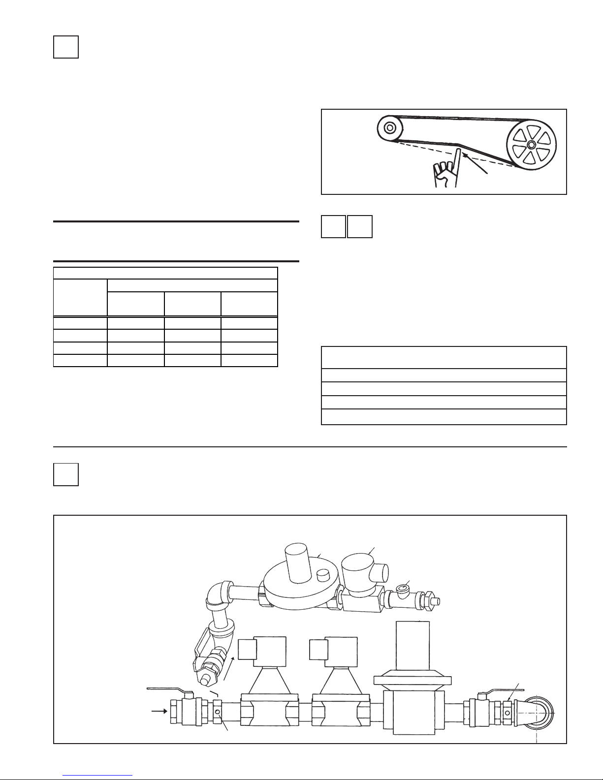
3. Manifold Gas Pressure
S
Semiannually, check the gas pressure to the burner and to the pilot. Measure both manifold pressure and pilot supply pressure with the blower in
operation. Refer to Figure 3 for pressure tap locations. Verify against pressures listed on the rating plate.
R E
If the system includes filters, check the filters quarterly. Filters could
be either in the optional inlet base or in an optional filter cabinet.
If the filters are in the perimeter of the inlet base; they are two-inch
permanent filters. Remove and clean the filters as needed.
If the filters are in a filter cabinet (the filter cabinet is always between
the inlet base and the burner/control section), remove the filter cabinet
door panels to access the V-bank filter rack. Filters may be either 2"
disposable, 1" or 2" permanent, or 1" or 2" disposable pleated. Clean or
replace as needed.
Size 109 112 115 118 122 125
16" x 16" 4 4 - - 16 16
16" x 20" 4466- -
16" x 25" - - 6688
2. Filters
Sizes and Quantity of Filters in the Filter Cabinet
( same for all types of filters)
Figure 3 - Location of
pressure taps for
measuring burner and
pilot gas pressure.
Measure with blower
operating.
Gas
Supply
Pilot Manifold
Valve
Inlet Pressure Tap
Pilot
Regulator
Valve
Pilot Solenoid Valve
Pilot Pressure Tap
Regulator
Manifold Pressure Tap
Page 3
Page 4
S
4. Air Pressure
Profile plate sensing tubes should be checked quarterly and cleaned no
less than semiannually. If the sensing tubes become even partially
blocked, false pressure readings may be relayed. To clean, remove the
screened end caps. Clean the screens and the tubes, if necessary. Replace the cleaned end caps. Check the pressure differential across the
profile plate using a slope gauge. Air pressure differential should be
between -.5" and -.7" w.c.
To attach the slope gauge, open the control compartment door panel.
Just below the junction box, locate the tubing connections. Remove the
cap at each connection and attach the slope gauge using two fieldsupplied 1/4" x 1/8" female NPT barbed tubing connections. For instructions on measuring air pressure, see Service Section, Paragraph 9.
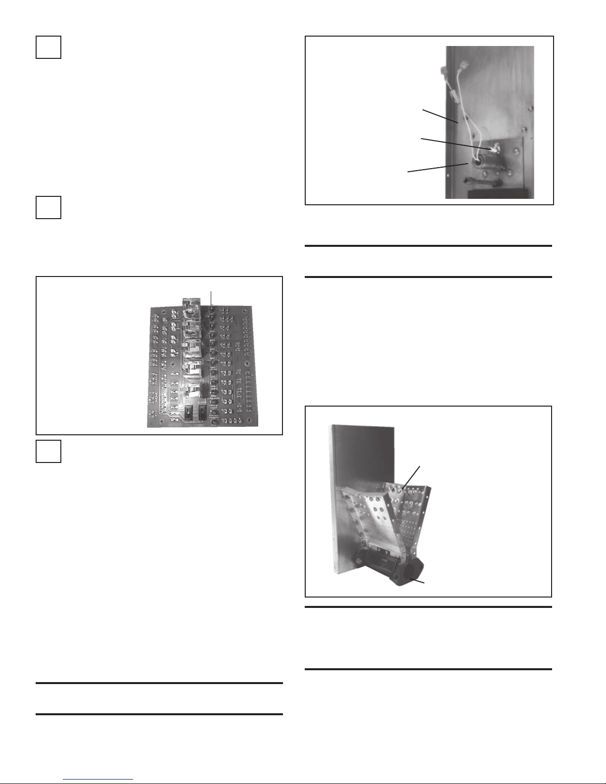
5. Circuit Indicator Board (check
R
lights)
The circuit indicator board is located in the control compartment electrical box (See Figure 7). Check operation of all indicator lights by
switching lights that are not lit with one that is currently lit. Replace all
burned out indicator bulbs (P/N 125189).
Figure 4 - Circuit
Indicator Board,
P/N 151263
Check bulbs not
lit with other
bulbs; replace
any burned out
bulbs
Row of Bulbs
Figure 5 - Burner
End Plate showing
Hot Surface Ignitor
Burner End Plate
Flame Sensor
Ignitor
If air pressure does not unplug burner orifices or pilot tube, drill
burner orifices with a Size #50 drill and/or pilot tube with a Size #55
drill.
WARNING: Do not enlarge burner ports or
performance may be drastically affected.
Inspect the upstream and downstream sides of the mixing plates.
Remove any accumulation of scale or foreign material with a wire
brush. If any mixing plate fasteners are loose or missing, tighten or
replace. Always use zinc plated or stainless fasteners.
If any cracks are present, replace that mixing plate. Because of the
effect of flame temperature on the metal, fasteners may be difficult
to remove. Be careful not to damage the gaskets that go between the
mixing plates and the burner body. The gaskets are designed to
overlap approximately 1/16" for tight air seal.
5) Follow Steps in reverse order to re-install the pilot assembly. Close
all panels and check for proper operation.
6. Main Burner and Pilot Assembly
S
For the most part, the burner and pilot are self cleaning. However, if the
application is extremely dirty or dusty, cleaning of the burner and pilot
may be necessary. Inspect the burner annually. Follow these instructions. If it is necessary to replace any parts, use only factory-authorized replacements.
1) Turn off the gas and power supply to the system.
2) Remove the door panels in the burner/control cabinet (four or six
depending on whether or not the system has return air). Locate the
pilot.
3) Disconnect the two ignition wires (male and female quick connections) and disconnect the flame sensor lead at the burner. Remove
the set screw located in the ignitor tube (set screw holds the brass
bushing in place). Carefully remove the brass bushing and the ignitor.
Check the hot surface ignitor for cracks or unusual deterioration.
Check the flame rod for integrity. Replace the flame rod (P/N 131188)
and/or the hot surface ignitor (P/N 121865) if not in good condition.
4) Clean the burner and pilot by back-flushing, using high pressure air
(40-80 lbs). Continue until dust particles are completely expelled
from both the upstream and downstream sides of the burner.
CAUTION: Wear eye protection while pressure
cleaning and drilling.
Figure 6 - Illustration of the first Burner Section
Mixing
Plate
Full length of the
burner is made up of a
series of 6" or 12"
burner sections in a
linear or oval
configuration
Burner
WARNING: Burner profile plates are factory set
to match CFM requirements.
Do not adjust profile plates without contacting your
Sales Representative for technical assistance.
Page 4
Page 5

Operation/Service Section
Controls - Location, Operation, and Service
To service this system, it is necessary to understand the normal operation
of the controls and the function of the diagnostic circuit board. Refer to the
electrical box drawing in Figure 7 and to the individual illustrations to
identify and locate each of the controls. The wiring diagrams for this unit
are located in the main electrical box.
Figure 7 - Control Locations
Control
Relays
(high ambient limit control)
Ignition
Module
Outside Air Cutoff
Bypass
Damper
Motor
WARNING: Service work on this system
should only be done by a qualified gas service person. The service information and
the troubleshooting guides are intended as
an aid to a qualified service person.
Time Delay
Relay
24-volt Terminals
Return
Air
Damper
Motor
Status Lights
Maxitrol Amplifier
or Signal Conditioner
Optional
Dirty Filter
Pressure Switch
Circuit
Board
Optional Bypass Damper
Pressure Switches
Service
Switches
24-Volt Terminals
High
Standard Pressure
Switches
Low
Relay for
Optional 2-Speed
NOTE: Wiring diagrams for the unit are located on the inside of the electrical box door.
7. Electronic Circuit Board with Diagnostic
Lights
Location: Control Compartment Electrical Box (See Figure 7)
Function: The diagnostic lights on the circuit board are designed to assist
in troubleshooting. When the system is operating properly, the lights on
the circuit board are lit. If the system fails to operate properly, all lights on
the circuit board up to that one that represents the component or system
that has failed will be lit. For more detailed information, refer to the Troubleshooting Guide in Paragraph 19.
8. Temperature Limit Safety Controls
Location: 1) Manual Reset Limit Switch is mounted on a 2x4
electrical box located in the blower section. To access the manual
reset, remove the blower section access panel to the left of the
discharge (left when facing the discharge); 2) Emergency Cutoff
Limit Control is in the burner/control cabinet just above the electrical box.
• Manual Reset Limit Control - Blower
Cabinet
Function: The
Figure 8 Diagnostic
Circuit
Board,
P/N 151263
Column of 13
indicator
bulbs; always
replace
burned out
bulbs, P/N
125189.
manual reset limit
is a temperature
activated safety
control. Re-start
of the system can
be done only after
the limit control is
cooled and the reset button is depressed.
CAUTION: If the manual reset limit activates,
find and correct the cause before re-starting the
system.
Service: Failure of the manual reset limit requires replacement of
the control.
Transformer
Starter
Relay
Figure 9 Manual Reset
Limit
Capillary tubing is
in a holder that
extends into the
Motor
Starter
Line Voltage
Terminals
Page 5
Page 6

8. Temperature Limit Safety Controls (cont'd)
• Emergency Cut Off Limit Control
Function: The emergency cut off is a fus-
ible link high temperature limit which provides one-time redundant protection
against overheating. If the temperature
sensitive limit control malfunctions, the
electrically activated emergency cutoff will
shutdown the system.
Service: If this limit activates, the manual
limit control has failed and must be replaced. The cause for activating the emergency cut off limit control must be found and corrected before restarting the system.
Figure 11 - ECO
Limit Control,
P/N 82414
Setting 305oF
9. Air Pressure Switches
Location: Control Compartment Electrical Box (See Figure 7.)
Depending on the options selected, there are two or four switches.
Figure 12 - Air
Pressure Switch
Attach a slope gauge (0 to 1.0" scale) to the tubing connections in the
control compartment. The two connections are located below the electrical control box. Remove the caps on the 1/8" NPT test connections
and attach the slope gauge. (The recommended method for attaching the
slope gauge is to use field-supplied 1/8" female NPT x 1/4" O.D. barbed
hose connections.)
A) If the system includes an optional discharge damper, before measur-
ing burner differential air pressure, check to be sure that the damper
is fully open.
B) With the blower operating, the pressure differential on the slope
gauge should read between -.5" and -.7" w.c. If the slope gauge
reading is within those limits, no adjustments are necessary.
If the slope gauge reading is not within the setpoint limits of the air
flow switches (.2" to .9" w.c.), and the system is operating, replace
the air pressure switch(es).
If the slope gauge reading is not between -.5" and -.7" w.c., but
within the setpoint limits, clean the sensing tubes (Follow the instructions in Maintenance Section, Paragraph 4).
C) When air pressure is within the proper range, turn the disconnect
switch OFF. Disconnect the manometer and the slope gauge. Replace the caps removed to connect the slope gauge.
Service: If the pressure check determines that an air flow switch is not
functioning properly, the switch cannot be serviced and must be replaced with an identical replacement. Low air pressure switch is P/N
86986; high air pressure switch is P/N 86987; bypass damper switches,
P/N 87249 (normally closed, set to open at .5" w.c.) or P/N 87250
(normally open, set to close at .65" w.c.).
• Low Air Flow Switch
Function: The low air flow switch is a velocity pressure switch that
monitors air flow across the burner. Until the air flow attains adequate
volume for combustion, the switch remains open. When the switch
recognizes adequate air volume, it closes, permitting both the pilot and
burner to operate. Low pressure switch is normally open; it closes on
pressure rise at .2" w.c. Do not alter or adjust setting.
• High Air Flow Switch
Function: The high air flow switch is a velocity pressure switch that
monitors air flow across the burner. If the high air flow switch senses air
velocity above the prescribed limit, it will shutdown gas flow to the
burner. High pressure switch is normally closed; it opens when pressure rises above .9" w.c. Do not alter or adjust setting.
• Bypass Damper Air Flow Switches (systems
with Air Control Options AR19, AR20, AR22, AR23,
AR32, AR33, AR34, AR36, or AR37)
Function: With a bypass damper, the volume of outside air supplied
to the building is adjusted by a manually set potentiometer (Option
AR19 and AR22) or automatically by a pressure null switch (Option
AR20 or AR23), a photohelic pressure switch (Option AR36 or AR37),
or a field-supplied computer signal (Option AR33 or AR34). With
Options AR19, AR20, AR33, and AR36 the supply air is varied by
adjusting the position of a damper at the blower discharge. With Options AR22, AR23, AR34, and AR37, a return air damper is adjusted to
vary the volume of return air. The unit is arranged so that a fixed amount
(20%) of the rated volume flows over the burner at a constant velocity.
The remainder (80%) of the rated air volume flows either through a
balancing bypass damper or a combination of bypass and return air
dampers. As the supply air volume is varied by the return air or discharge damper, the balancing damper is adjusted to maintain the required air velocity over the burner. Adjustment of the bypass damper is
controlled by the bypass damper pressure switches. One pressure
switch is normally closed with a setting of .5" w.c.; the other is normally open with a setting of .65" w.c. balancing bypass damper.
Sensing Pressure Check: (requires a slope gauge, several feet of
1/4" O.D. tubing and two 1/4" O.D. barbed tees.)
Page 6
10. Ignition System
Location: Ignition Controller Module in the Control Compartment
Electrical Box (See Figures 7 and 13.); Ignitor and Flame Sensor on the
Burner (See Figure 14.)
Figure 13 - Ignition Control
Module in the Electrical
Compartment, P/N 157953
Hot Surface Ignition System with Prepurge
Time Delay and Flame Sensor with 100%
Lockout
Function: The ignition system including the controller, the hot surface
ignitor, and the flame sensor function to ignite and prove the pilot
flame. When there is a call for heat, the modular ignition controller is
energized. When the controller reads 1.4 amps going to the hot surface
ignitor, it opens the pilot valve for a 15-second trial for ignition. After
the pilot flame rod senses pilot flame, the main gas valve is energized. If
the pilot flame rod does not sense a pilot flame, the controller shuts
down the pilot valve for a 10-second interpurge and then opens it again
for a second ignition trial. If pilot flame is not proven on the second
trial, the ignition controller locks out and must be manually reset by an
interruption of the main circuit (disconnect switch).
Service: The modular ignition controller does an internal self-check
each time that it is energized and will lockout if not found to be func-
Figure 14 - Ignitor, P/N
121865, and Flame
Sensor, P/N 134706, on
the Burner
Sensor
Ignitor
Page 7

tioning properly. If the ignition controller locks out and there is no
other cause, the controller module must be replaced.
11. Gas Train Including Direct-Fired
Burner, Gas Control Systems,
Manifold Arrange-ments, and Gas
Pressure Switches
Direct-Fired Burner
Function: The design of the direct-fired burner and the con-
trolled velocity of air at the burner ensure complete combustion
through the full range of burner sizes and gas inputs as determined
by the gas control system. The velocity of air is controlled by the
profile plates and monitored by a standard low and high air pressure switch.
Service: Refer to Paragraph 6 in the Maintenance Section for
instructions on burner maintenance.
For troubleshooting guides and further explanation of Maxitrol Series 14 and
44 electronic modulation gas control systems, refer to the Maxitrol literature
in the owner's envelope.
The Option AG30, AG31, AG32 and AG35 electronic modulation systems
are comprised of Maxitrol Series 14 controls. Options AG30 and AG31
systems electronically maintain a constant discharge air temperature in the
range of 55-90°F (55-75°F for C.G.A.). Option AG31 includes an overriding
thermostat. Option AG32 system will maintain a constant discharge air
temperature in the range of 80-130°F. Option AG35 maintains a discharge
temperature range of 120-160°F.
Figure 15 - Components of the Gas Control System (Maxitrol
Series 14) used in Gas Control Options AG30, AG31, AG32,
and AG35
Amplifier,
P/N 148590
Mixing
Tube
WARNING: Burner profile plates are factory
set to match CFM requirements. Do not adjust
profile plates without contacting your Sales
Representative for technical assistance.
Makeup Air Gas Control Systems
• Electronic Modulation Gas Control
Options AG30, AG31, AG32, AG33, AG35,
AG36
Refer to the wiring diagrams in the main electrical box to determine which controls are on the system being serviced. NOTE: All
field-supplied control wiring for Maxitrol controls must not be
run inside conduit with line voltage wiring. To avoid any potential
electrical interference, all field-supplied wiring for Maxitrol controls should be shielded wiring and must be grounded at the unit
only.
Function: These makeup air gas control systems provide heated
makeup air at a temperature controlled by a discharge air sensor.
Each system is equipped with electronic modulation controls
that modulate burner flame from 1/25th of full fire input to full
fire.
The electronic modulating-type gas controls act in response to
discharge and/or room air temperature sensors to change the gas
flow rate to the burner, thus lengthening or shortening the flame.
The BTU output is varied (modulated) to maintain the required
discharge air temperature.
These modulating gas control options are electronic because in all
cases the gas valve acts to adjust the flow of the gas to the main
burner in response to DC volts emanating from an amplifier.
When the DC voltage is between 0 and 5 volts, the main valve seat
is closed. Low fire flow is accomplished through a mechanical
bypass. The low fire flow rate is set at the factory and should not
need adjustment. However, if adjustment is necessary, refer to
the Maxitrol literature that is included in the heater owner's envelope.
All of the electronic modulating gas control burner systems include low fire start. On an initial call for heat, the main burner
ignites at its lowest input. During mild weather, the burner may
then cycle off. Such full shutdown can be dictated by the outdoor
ambient cutoff control. As the outside air temperature climbs
above the setpoint of the outdoor ambient control, the burner
control circuit is de-energized. When moderately cold outside air
temperatures exist, the burner will modulate between low flame
and high flame. Low fire start and the outdoor ambient control
prevent the makeup air system from heating already warm air and
providing "too much" heat to the building.
Temperature
Selector
Option AG33 electronic modulation system is comprised of Maxitrol Series
44 controls. The low limit (20-60°F) and the high limit (60-140°F) for control of discharge air temperature are set at the amplifier located in the control
compartment. The space temperature is set at the remote selectrastat (5590°F range) located in the space. When the temperature is below the space
temperature setpoint, the control system operates the burner to automatically adjust the discharge air temperature within the maximum and minimum
limits set on the amplifier.
Temperature
Sensor
Figure 16 - Components of the Gas Control System (Maxitrol
Series 44) used in Gas Control Option AG33
Temperature
Sensor,
P/N 119617
Mixing Tube,
P/N 90323
Option AG36 is a special application gas train that is designed for controlling
the environment of a paint booth operation. The system includes a Maxitrol
A1494 amplifier, discharge air temperature sensor, dual remote discharge air
temperature selector (drying selector 80-140°F and a spray selector 6090°F), and two switches to control the operation of the modulating gas valve.
Amplifier,
P/N 157915
Temperature
Selector, P/N 86990
Figure 17 - Components of the Gas Control System used in
Option AG36 designed specifically for paint booths - controls
are mounted on a remote console
Selector,
Amplifier,
P/N 133229
Electronic Modulation
Gas Control Option
AG37
Function: Control Option AG37
does not have a duct sensor or amplifier. Instead, a Maxitrol A200 signal
conditioner is activated by a customer-supplied input signal (either 420 milliamps or 0-10 volt) to control
the modulation of the gas valve.
P/N
133230
Figure 18 - Maxitrol A200
Signal Conditioner,
P/N 134170, used in Gas
Control Option AG37
Page 7
Page 8
11. Gas Train Including Direct-Fired Burner, Gas Control Systems, and Manifold
Arrangements (cont'd)
Service - All Maxitrol Controls: Check all electrical connec-
tions. A qualified service person should refer to the Maxitrol Troubleshooting Guides for assistance in identifying problems and determining
the correct solution. None of the Maxitrol controls have field replaceable parts. All components must be replaced with identical replacement
parts.
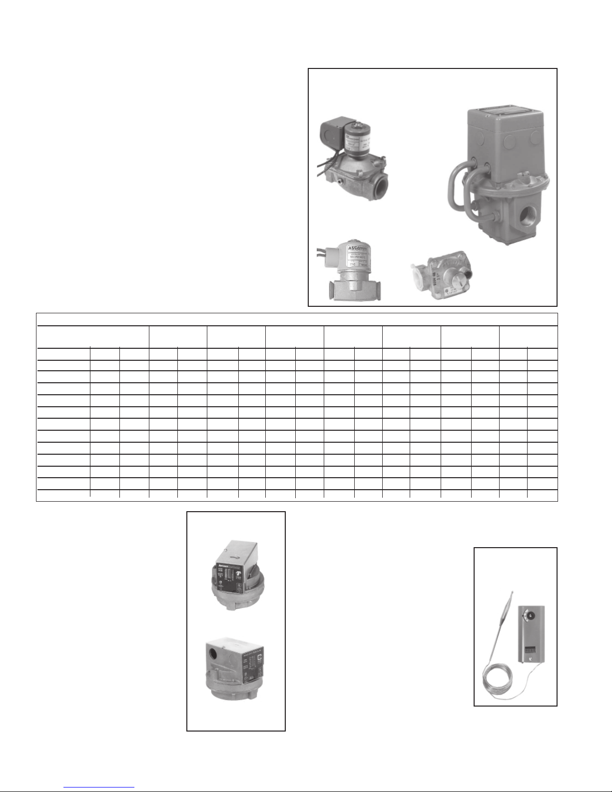
Figure 19 - Gas Manifold Control Components
Solenoid Valve
Modulating/
Regulating
Valve
Manifold Arrangements
Description: The manifold is the gas train from the gas supply con-
nection to the burner. The manifold selection ordered determines the
manifold arrangement including all of the gas train components except
the main control valve. Manifold arrangements are available for varying
BTUH ranges and gas controls and include versions that meet FM or
IRI requirements.
In addition to the Maxitrol valve and two solenoid valves, all manifold
arrangements include main gas and pilot gas shut-off cocks, a pilot
regulator, and a pilot solenoid valve.
The table below lists the pressure drops through the various types of
manifolds by option designation (BM). To determine the required minimum supply pressure for natural gas, add 5.0" w.c. to the natural gas
manifold pressure drop. For propane gas, add 2.0" w.c.
Manifold Pressure Drops (“ w.c.)
Manifold Opt BM62 BM63 BM64 BM65 BM67 BM68 BM53 BM66
Manifold Size 1" 3/4" 1" 1-1/4" 1-1/4" 2" 1-1/4" 2"
MBH Nat Pro Nat Pro Nat Pro Nat Pro Nat Pro Nat Pro Nat Pro Nat Pro
250 .56 .21 .66 .25 .43 .17 .22 .09 .19 .07 .07 .03 .22 .09 .07 .03
500 2.23 .85 2.65 1.01 1.74 .66 .89 .34 .76 .29 .27 .10 .89 .34 .27 .10
750 5.02 1.91 5.96 2.27 3.91 1.49 2.01 .77 1.71 .65 .61 .23 2.01 .77 .61 .23
1000 -- -- -- -- 6.95 2.65 3.58 1.36 3.04 1.16 1.09 .41 3.58 1.36 1.09 .41
1250 -- -- -- -- -- -- 5.59 2.13 4.76 1.81 1.70 .65 5.59 2.13 1.70 .65
1500 -- -- -- -- -- -- 8.05 3.07 6.85 2.61 2.44 .93 8.05 3.07 2.44 .93
1750 -- -- -- -- -- -- 10.96 4.17 9.32 3.55 3.33 1.27 10.96 4.17 3.33 1.27
2000 -- -- -- -- -- -- 14.31 5.45 12.18 4.64 4.34 1.66 14.31 5.45 4.34 1.66
2250 -- -- -- -- -- -- 18.11 6.90 15.41 5.87 5.50 2.09 18.11 6.90 5.50 2.09
2500 -- -- -- -- -- -- 22.36 8.52 19.02 7.25 6.79 2.59 22.36 8.52 6.79 2.59
2750 -- -- -- -- -- -- -- -- -- -- 8.21 3.13 -- -- 8.21 3.13
3000 -- -- -- -- -- -- -- -- -- -- 9.77 3.72 -- -- 9.77 3.72
Gas Pressure Switches
If the gas train includes either or both
high and low gas pressure switches,
the switches monitor gas pressure
downstream from the safety valves.
If the gas pressure in a system equipped
with a high gas pressure switch (Option BP2) exceeds the setpoint, the
switch will open the electrical circuit
to the burner, stopping all gas flow.
The high gas pressure switch is a manually reset device.
A low gas pressure switch (Option
BP3) will shutoff the gas flow if the
gas pressure drops below the setpoint
of the low pressure switch. The low
gas pressure switch will automatically
reset when the gas pressure rises above
the setpoint.
(NOTE: Both high and low gas pressure switches incorporate a vent limiting device and do not require
venting to the outdoors when used in an application installed indoors.)
Page 8
Figure 20 - Gas
Pressure Switches
Low, P/N 93850
(automatic)
High, P/N 93849
(manual reset)
Pilot Valve
Pilot Regulator
12. Outside Air Cutoff Control (Option BN2;
required on C.G.A.-certified units)
Location: The control is in the electrical
box (See Figure 7.); the sensor is in the air
inlet.
Function: After sensing pilot flame, the
burner ignites at its lowest input rate. The
"amount of heat" required to reach the desired discharge temperature also depends on
the temperature of the incoming outside air.
The outside air control is factory set at 60°F
(adjustable 25-250°F). The burner reacts
differently depending on the entering air temperature and the setting on the outside air
control. The burner --
• may not ignite (pilot valve will not open);
If the actual temperature of the outside
air is above the setpoint on the outside air control, the burner will
not ignite.
• may modulate to satisfy discharge setting;
• may shutdown; or
Figure 21 Outside Air
Cutoff Control
Page 9

Burner shutdown or modulating operation will depend on the temperature rise between the outside air and the discharge air setting.
• may remain on continuous low fire.
If the outside air control is set too high, the burner will continuously
burn on low fire as long as the control switch is set to "winter".
When the outside air control is set properly for the climate, the system
blower will continue to provide the required makeup air (ventilation) at
the ambient outdoor temperature (burner not operating) even when the
control switch is set to "winter".
Service: If the control does not function properly, replace it with an
identical switch.
13. Door Switch (Option BX1; required on
C.G.A.-certified units)
Location: The control is installed on an overhead door opening to control the operation of
the heater to coincide with the opening and closing of the door.
Function: The function of the switch is to energize and interlock the heating unit when an outside overhead door reaches approximately 80%
of full open travel. The switch will de-energize
the furnace when the overhead door closes approximately 20%. The complete switch includes
a limit switch electrically wired to the heater and a roller yoke for
mechanical activation by a field-supplied trigger on the overhead door.
Figure 22 Door Switch,
P/N 124253
14. Inlet Air Controls
WARNING: Burner profile plates are factory set
to match CFM requirements.
Do not adjust profile plates without contacting your
Sales Representative for technical assistance.
Description: The system is equipped with one of the 11 types of
inlet air control arrangements listed below. All systems provide a constant flow of outside air across the burner at the required air volume
(CFM).
Refer to the wiring diagrams in the main electrical box to determine
which controls are on the system being serviced.
zz
zOption AR1 - a constant supply of 100% makeup air
zz
zz
zOption AR19 - 100% outside makeup air with variable supply air
zz
volume (CFM). The discharge damper controlling the variable air supply is controlled by a manually set remote potentiometer and can be
varied from 100% to 20% of total rated air flow (CFM). In response to
changes in the discharge damper setting, the bypass damper balances
the volume of air so that the required fixed amount of air volume flows
over the burner.
zz
zOption AR20- 100% outside makeup air with variable supply air
zz
volume (CFM). The discharge damper controlling the variable air supply is automatically controlled by a building pressure sensor and can be
varied from 100% to 20% of total rated air flow (CFM). In response to
changes in the discharge damper setting, the bypass damper balances
the volume of air so that the required fixed amount of air volume flows
over the burner.
zz
zOption AR22 - a combination of outside makeup air and bypass
zz
return air including modulating return air and bypass air dampers. The
volume of outside air is regulated by a remotely located, manually set
potentiometer.
zz
zOption AR23 - a combination of outside makeup air and bypass
zz
return air including modulating return air and bypass air dampers. The
volume of outside air is regulated automatically by a remotely located
building pressure sensor.
zz
zOption AR32 - a combination of outside makeup air and bypass
zz
return air including a two-position actuator. The two position actuator
changes the position of the damper to provide either 100% outside air
or 20% outside/80% return air. Control is from a SPDT toggle switch
mounted on a 4x4 box (or if ordered, the switch is mounted on a remote
console).
zz
zOption AR33 - 100% outside makeup air with variable supply air
zz
volume (CFM). The discharge damper controlling the variable air supply is automatically controlled by a 0-10 VCD or 4-20 milliamp signal.
In response to changes in the discharge damper setting, the bypass
damper balances the volume of air so that the required fixed amount of
air volume flows over the burner.
zz
zOption AR34 - a combination of outside makeup air and bypass
zz
return air including modulating return air and bypass air dampers. The
volume of outside air is regulated by a 0-10 VCD or 4-20 milliamp
signal.
zz
zOption AR35 - a constant supply of 100% makeup air to the unit but
zz
including a two-position inlet shutoff damper that closes the dampers
when the system is not operating. The damper attaches to the duct
flange of the optional inlet base (used only with the optional inlet base
that has three closed sides and a duct connection for outside air).
zz
zOption AR36 - 100% outside makeup air with variable supply air
zz
volume (CFM). The discharge damper controlling the variable air supply is automatically controlled by a remotely located photohelic pressure sensor. In response to changes in the discharge damper setting, the
bypass damper balances the volume of air so that the required fixed
amount of air volume flows over the burner.
zz
zOption AR37 - a combination of outside makeup air and bypass
zz
return air including modulating return air and bypass air dampers. The
volume of outside air is regulated by a remotely located photohelic
pressure sensor.
Air Flow Dampers
Function: Dampers operate in response to controls to provide the
rated flow of makeup air to the building.
Service: Clean dampers of dust or dirt.
Damper Motor
Function: The damper motor automatically actuates the return air, bypass, and/or discharge
dampers in response to an electrical control device. The damper motor is direct-coupled to the
dampers so there is no damper linkage to adjust.
Service: There is no service required on these
motors other than external cleaning. If the motors need replaced, replace with an identical
damper motor.
Potentiometer
Function: The potentiometer is a manually set
switch that operates either the discharge damper
(Option AR19) or the return air damper (Option AR22) providing a mixture of return and
outside air. It is a remotely located switch that
requires manual adjustment.
Figure 23 Damper Motor
Figure 24 Potentiometer,
P/N 16110
Service: If the potentiometer does not func-
tion properly, replace it with an identical switch.
Pressure Null
Switch (automatic
building pressure
sensor)
Description/Function:
The pressure null switch is
a diaphragm operated differential pressure switch used
in makeup air applications
to automatically control
Figure 25 Pressure
Null Switch
(building
pressure
sensor),
P/N 88052
Page 9
Page 10

14. Inlet Air Controls (cont'd)
Pressure Null Switch (cont'd)
building pressure. It maintains a selected positive or negative pressure
setpoint by changing the amount of outside air being introduced to the
building through modulating outside air damper. As more pressure is
required in the building, the pressure null switch activates the damper
motor driving the outside air damper towards the full open position
(causing the bypass return air damper to go toward the closed position). Conversely, as less pressure is required, the switch drives the
outside air damper in the opposite direction.
Service: Clean the tubing and the screened ends of the pressure tap
vents. Be sure that the switch is installed with the diaphragm in a
vertical plane and that the pressure taps are sheltered from the wind.
For further service, follow the manufacturer's instructions included
with the switch.
Photohelic Pressure Switch (automatic
building pressure sensor)
Description/Function: The
photohelic pressure switch is a
phototransister relay operated
positive pressure switch used
in makeup air applications to
automatically control building
pressure. It maintains a selected
positive pressure setpoint by
changing the amount of outside
air being introduced to the
building through a modulating outside air damper. As more pressure is
required in the building, the switch activates the damper motor driving
the outside air damper towards the full open position (causing the
bypass return air damper to go toward the closed position). Conversely, as less pressure is required, the switch drives the outside air
damper in the opposite direction.
Service: Clean the tubing and the screened ends of the pressure tap
vents.
If the interior of the switch is protected from dust, dirt, corrosive gases
and fluids, years of trouble-free service may be expected. Zero adjustment should be checked and reset occasionally to maintain accuracy;
follow the manufacturer's instructions included with the switch.
There are no field-repairable parts in this switch. If the switch should
require repair, contact either the system or the switch manufacturer
concerning switch replacement or repair.
Figure 26 Photohelic
Pressure
Sensor,
P/N
159893
15. Dirty Filter Switch
Location: Switch is located in the
main electrical box (See Figure 7);
sensor tubes run to either side of
the filter rack; indicator light is on
the remote console.
Function: The dirty filter
switch is a pressure switch that
activates an indicator light on the
remote console when the filters
need cleaned or replaced (See Service Section, Paragraph 2). This
Figure 27 - Dirty Filter
Pressure Switch, P/N
105507
switch is only on systems with an optional console that includes a dirty
filter light. The pressure switch is set during installation so that the light
will be activated at approximately 50% filter blockage. Contacts should
close at .17 to 5.0" w.c. ± .05" w.c.
Service: Clean the sensor tubes. If the dirty filter indicator system still
does not function properly, check the setting of the switch. With clean
filters in place, blower doors closed, and blower in operation, decrease
the pressure setting by adjusting the set screw on the switch clockwise
until the filter light is energized or screw is bottomed out. At that point,
adjust the set screw three full turns counterclockwise or until the screw
is top ended.
If it is determined that the switch needs replacing, use an identical
switch. When a new switch is installed, it must be manually set; follow
the instructions above.
16. Photoelectric Smoke Detector (Option
SA1)
Location: Field-mounted in
the discharge ductwork.
Function: The detector will
shut down the system if
smoke is detected in the discharge ductwork.
Service: Clean the external
surface. Check the wiring and
connections.
Figure 28 - Photoelectric Smoke
Detector (cover removed), P/N
159553, used with sampling tube,
P/N 159714
17. Firestat (Option BD5)
Location: Field-mounted on the discharge ductwork so that the sensor
extends into the duct. This control
requires manual reset so should be
mounted in an accessible location.
Function: The firestat will shut
down the system if the temperature
in the ductwork reaches 200°F. The
switch must be manually reset.
Service: Clean the external surface. Check the wiring and connections.
Figure 29 Firestat,
P/N 42782
18. Freezestat (Option BE2)
Location: The control is in the
blower section electrical box; the
sensing bulb is field-mounted in the
discharge duct.
Function: The freezestat will shut
down the system if the discharge
temperature falls below the
setpoint. The switch is automatic
and will startup the heater when
the temperature reaches the
setpoint.
Service: Clean the external surface.
Check the wiring and connections.
Figure 30 - Freezestat
Controller, P/N 126170
REFERENCE: For service and troubleshooting information on the electrical controls, refer to the
manufacturer's literature covering that component. Component literature is included in the literature
Refer to Paragraph 19 for unit troubleshooting.
Page 10
envelope shipped with the system.
Page 11

19. Troubleshooting
Chart 1 - General Troubleshooting Guide (Check the diagnostic lights on the circuit board)
Symptom or Problem Cause and Remedy
Disconnect switch is closed, but
1.
Disconnect switch is closed, but
2.
Disconnect closed, blower switch in test position, 1. Freezestat option not ordered - verify order/wiring diagram.
3.
"firestat"
Disconnect closed, blower switch in test position, "firestat" and 1. End switch on damper motor not closed. - check end switch wiring.
4.
"free ze stat"
and the blower motor is not operating. 3. Damper motor miswired - rew ire damp er motor per wiring diagram.
Disconnect closed, blower switch in test position, 1. Blower motor not wired correctly - check wiring diagram on motor.
5.
"firestat", "freezestat"
lights are lit, but t he blower motor is not operating. 3. Faulty blower mot or relay - rep lace relay .
Disconnect closed; blower switch in test position;
6.
"free ze stat"
blower motor is operating; but t he "low air light" is not lit. 3. Faulty low air switch - replace pressure switch (P/N 86986).
Disconnect closed; blower switch in test position; 1. High air switch open - verify p ressure drop at burner.
7.
"firestat", "freezestat", "starter energized"
air"
but t he
Disconnect closed; blower switch in test position;
8.
"free ze stat", "starter energiz ed", "l ow air" and "high air"
are lit; but the
Disconnect closed; blower s wit ch in test p osition; 1. Indicator light is burned out - rep lace bulb (P/N 125189).
9.
"firestat", "freezestat", "starter energized", "low air",
"high air"
but t he
10.
"firestat", "freezestat", "starter energized", "low air",
"high air", "limit control normal"
cutoff normal "
pressure n ormal"
11.
"firestat", "freezestat", "starter energized", "low air",
"high air", "li mit controls normal", "ambient (outside air)
cutoff normal"
but t he
12.
posit ion; control s wit ch is in "winter" p osition; cause then rep lace ECO .
"control power", "high gas normal"; "low gas normal";
"firestat normal"; "system switch energize d"; "starter
energized"
ignitor is not becoming energized or beginning to glow. 4. Faulty low stage relay - replace relay.
13. Disconnect closed; blower and burner switches in run 1. Ignitor not reaching 1.4A threshold - check voltage and
position; control switch is in "winter" position;
high gas normal; "low gas normal "; "fi restat normal"; "system
switch energized"; "starter energized" and "freezestat normal"
lights are lit; ignitor glowing but
(thus the pilot valve) is not energized.
light is lit, but
lights are lit, but
and
lights are lit and the blower motor is operating; 3. High air switch option not ordered - verify order/wiring diagram.
"high air light"
"limit control normal"
and
"limit control normal"
"ambient (outsi de air) cutoff normal"
Disconnect closed; blower s wit ch in test p osition; 1. Indicator light is burned out - rep lace bulb (P/N 125189).
lights are lit; but the
Disconnect closed; blower s wit ch in test p osition; 1. Indicator light is burned out - replace bulb (P /N 125189).
and
"high gas pressure normal"
Disconnect closed; blower and burner switches in run 1. Lack of power at L1 on ignition module - ECO blown, find
and
"freezestat normal"
"free ze stat"
and
"starter energized"
is
light is
"low gas pressure normal"
"control power"
"firestat normal"
light is not lit 2. Freezest at relay cont acts are open - checking setting on cont rol.
"starter energized"
"starter energized"
lights are lit and t he 2. Indicator light is burned out - replace bulb (P/N 125189).
lit. 4. Faulty high air switch - rep lace pressure switch (P/N 86987).
not
light is not lit. 3. Faulty manual limit cont rol (s) - rep lace limit cont rol.
lights are lit; 3. High ambient control contacts open - check setting on control.
and
"ambient (outsi de air)
"low gas
lit. 5. Faulty gas p ressure switch - rep lace gas p ressure swit ch.
not
light is
lights are lit; but thermostat sett ing.
"pilot valve normal"
light is not lit. 1. Fuses are missing or blown in disconnect switch - replace fus es.
2. T ransformer not wired according to diagram - check wiring.
3. Secondary 8A fuse (on transformer) is missing or blown - replace fuse.
4. Indicator light is burned out - rep lace bulb (P/N 125189).
light is not lit. 1. See causes and remedies for Problem 1 above.
2. Op tional control relay or door switch contacts are open - to test ,
jump terminals 3 to 4 or 1 to 2.
3. Firestat opt ion not ordered - verify order/wiring diagram.
4. Firestat manual reset tripped - reset firestat control.
3. Indicator bulb is burned out - rep lace bulb (P/N 125189).
light is not lit 2. Faulty damp er relay - replace relay .
2. Faulty motor start er - rep lace (check coil firs t).
"firestat"
and
"low
"firestat"
light is
lights are lit; 4. High gas pressure switch contacts open - check gas p ressure.
lit. 5. M anual reset on switch tripp ed - reset p ressure switch manual reset.
not
"control power",
light
, 1. Low air switch open - verify p ressure drop at burner.
2. Indicator light is burned out - rep lace bulb (P/N 125189).
, 1. Indicator light is burned out - replace bulb (P/N 125189).
2. T rip p ed manual reset limit control(s) - reset manual cont rol.
2. High ambient control op tion not ordered - verify order/wiring diagram.
lit.
not
2. Low gas pressure switch option not ordered - verify order/wiring diagram.
3. Low gas pressure switch contacts op en - check setting on control.
4. Low gas pressure switch contacts op en - check gas pressure.
2. High gas pressure switch op tion not ordered - verify order/wiring diagram.
3. High gas pressure switch contacts open - check setting on control.
6. Faulty gas p ressure switch - rep lace gas p ressure swit ch.
2. Faulty burner enable relay - rep lace relay .
3. Low stage relay cont act s are not closed - check air cont roller or
5. Faulty hot surface ignitor - check cont inuity at the ignition module
and circuit board. If reading is greater than 5-6 ohms, replace ignitor.
6. Faulty ignition module - replace entire module.
current to ignitor.
2. Faulty hot surface ignitor - check cont inuity , replace ignitor.
3. Faulty ignition module - replace entire module.
Page 11
Page 12

19. Troubleshooting (cont'd)
Chart 1 (cont'd) - General Troubleshooting Guide (Check the diagnostic lights)
Symptom or Problem (cont'd) Cause and Remedy (cont'd)
14. Disconnect closed; blower and burner switches in run position; control 1. Air in pilot gas line - bleed pilot line.
switch is in "wint er" p os ition;
gas normal"; "firestat normal"; "system switch energize d"; "starter
energized" and "freezestat normal"
1.4A and has opened the pilot valve bringing on the
light; but t he p ilot flame is not present . (Aft er two t rials the unit will go
into safety lockout requiring cycling of the main disconnect switch.)
15. Disconnect closed; blower and burner switches in run position; 1. M icroamp signal on flame rod is inadequate - check position and
control switch is in "winter" p osition; all status light s are lit condition of flame rod and signal (minimum 0.5 microamps required.)
"main valve normal" light. The pilot flame is present 2. Grounding for unit or flame rod inadequate - check ground path.
except
and stable, but the (low stage portion or) main gas valve will not 3. Fault y main gas valve - replace main gas valve.
open, or rap id cycling of the main valve is occurring. 4. Faulty ignition module - rep lace ignition module.
16. Disconnect closed; blower and burner switches in run position; 1. Faulty main gas valve - replace main gas valve.
cont rol swit ch is in "winter" posit ion; all s tatus lights are lit; the 2. Inadequate timing on high fire time delay relay - adjust setting.
pilot flame and low fire on the main burner are p resent and st able, 3. Faulty high fire t ime delay relay - replace t ime delay relay .
but the unit will not p rogress t o a high fire condit ion. 4. High st age relay contacts are not closed - check control setting.
"control power", high gas normal; "l ow
lights are lit; ignitor has reached 4. Faulty ignition module - rep lace entire module.
"pilot valve normal"
2. Inadequate pilot gas pressure - verify pilot gas pressure (3.5" w.c.)
3. Faulty p ilot valve - rep lace pilot solenoid valve.
5. Inadequate main gas pressure - verify main burner pressure.
5. Inadequate main gas pressure - verify main burner gas pressure.
6. Faulty high stage relay - replace relay.
7. Faulty ignition module - rep lace entire module.
FOR SERVICE OR REPAIR, FOLLOW THESE STEPS IN ORDER:
FIRST: Contact the Installer
Name ___________________________________________________________________________
Address ___________________________________________________________________________
___________________________________________________________________________
___________________________________________________________________________
Phone ___________________________________________________________________________
SECOND: Contact the nearest distributor (See Yellow Pages). If no listing,
contact Authorized Factory Representative, 1-800-695-1901 (Press 1).
®
THIRD: Contact REZNOR
150 McKinley Avenue
Mercer, PA 16137
Phone: (724) 662-4400
Model No. _____________________________________________
Unit Serial No. _____________________________________________
Date of Installation _____________________________________________
Index .................................................. Page
Air Pressure ............................................. 4
Air Pressure Switches ............................... 6
Blower Bearings ....................................... 3
Circuit Indicator Board ............................ 4
Control Locations .................................... 5
Damper Motor ........................................ 9
Direct-Fired Burner ................................. 7
Dirty Filter Switch ................................ 10
Drive Components ................................. 3
Electronic Circuit Board with
Diagnostic Lights ................................. 5
Emergency Cut Off .................................. 6
/Thomas & Betts Corporation
Index .................................................. Page
Filters ....................................................... 3
Firestat .................................................... 10
Freezestat ............................................... 10
Gas Control Systems ............................... 7
Gas Pressure ............................................ 3
Gas Pressure Switches .............................. 8
Inlet Air Controls ..................................... 9
Limit Control ........................................... 5
Main Burner ............................................. 4
Maintenance Schedule ............................. 2
Maintenance Section ......................... 2-4
Maintenance/Service Access .................... 2
Index .................................................. Page
Manifold Arrangements ........................... 8
Operation/Service Section .............. 5-12
Outside Air Cutoff Control ..................... 8
Photoelectric Smoke Detector ................ 10
Photohelic Pressure Sensor ..................... 10
Pilot Assembly ........................................ 4
Potentiometer ........................................... 9
Pressure Null Switch ............................... 9
Sensing Pressure Check ........................... 6
Troubleshooting ..................................... 11
Wiring Diagram ......................... In the main
electrical box on the unit
Page 12
©2001 Thomas & Betts Corporation, All rights reserved. Printed in the U.S.A.
MANUFACTURER OF HEATING, COOLING, AND VENTILATING SYSTEMS
Trademark Note: Reznor® is registered in the United States and other countries.
(800) 695-1901; www.ReznorOnLine.com
8/01 YL Form 441OMS (Version .1)
 Loading...