

Page 1

1
Enclosed you will find:
• Indoor Speaker • Wire Labels • Wire Nuts • Wall Anchors
• Outdoor Speaker • Transformer • Pull Cord • Screws
INSTALLATION
Replacement for Existing Chime
1. Locate Indoor Speaker where chime is located. In many cases
existing wiring can be used–see enclosed “Identifying Chime Wiring.”
2. If existing Chime is mounted at a height which is inconvenient to
reach, a pull cord is provided to operate the intercom control button.
3. Important: Do not locate speakers more than 500 feet apart. Do not
locate speakers back-to-back on the same wall.
4. Locate Outdoor Speaker where existing pushbutton is located. Use
pushbutton wiring–see enclosed “Identifying Chime Wiring.” Note: If
existing pushbutton is uneven or narrow surface, it will be necessary
to locate Outdoor Speaker elsewhere.
5. Install Outdoor Speaker: (A) on an even surface; (B) on a surface wide
enough for the speaker; (C) as close to existing wiring as possible.
Caution:
• Turn off house power at the source and leave it off until installation is
complete.
• All wiring must comply with local wiring codes.
New Installation Location
1. Install the Indoor Speaker at an easy operating location.
2. Install the Outdoor Speaker close to the door and at an easy
operating position.
3. Try to install speakers where running the wiring will not present a
problem. Avoid running the speaker wire next to any AC power
wires.
New Installation
1. Install a 16-volt transformer (Carlon Model DH905). Mount the
transformer to a junction box or a circuit breaker box. Do not mount
transformer in high temperature area (i.e., attic). Follow transformer
installation instructions. Connect primary side of the transformer to
120V AC.
2. Run standard 20 AWG (DH965) bell/chime wire from transformer’s
secondary terminals to the Indoor Speaker location.
3. Run standard bell/chime wire from the Outdoor Speaker location to
the Indoor Speaker location.
4. Connect brown Outdoor Speaker wires to green Indoor Speaker
wires shown in Figure 1.
5. Connect transformer wires to red Indoor Speaker wires as shown in
Figure 1.
6. Use wire nuts to make all connections. Insulate all connections with
electrical tape.
7. If electric door strike feature is required, see “Optional Electric Door
Strike Wiring.”
INSTRUCTION GUIDE
Door Chime Intercom DH720
Congratulations on a wise purchase!
Indoor Speaker
Outdoor
Speaker
Transformer
Green Wires Red Wires
120V AC
Primary
Brown
Wires
Figure 1
16V
Page 2
2
Identify the existing wiring by determining whether the common wire connection is at the transformer location
or at the chime location. Follow the instructions and diagrams for identifying the individual wires.
When wiring has been identified and labeled, proceed to installation instructions.
Chime
Front
Trans
Trans Trans
Rear
1. Disconnect the 3 common wires. 2. Touch each wire, one at a time, to the
chime’s FRONT terminal. The wire that
causes the chime to sound is the
TRANSFORMER wire. Label the wire TRANS.
3. One at a time, connect the remaining
wires to the wire labeled TRANS. Then,
operate the FRONT pushbutton. The wire
that causes the chime to sound, label
FRONT. Confirm that the other wire
operates the rear pushbutton. Label the
wire REAR.
4. Proceed to installation instructions.
1. Disconnect the two common wires located
on transformer screw terminal.
2. Connect one common wire to the
transformer terminal and press the FRONT
pushbutton. If wire operates the chime,
label the wire FRONT. If not, connect other
wire; and label wire FRONT.
3. Reconnect the REAR wire to the
transformer terminal. (The FRONT wire
can be used for connection to the
Door Speaker.)
Wiring #1: Front and rear door pushbuttons - Common wire connection at chime
Wiring #2: Front and rear door pushbuttons - Common wire connection at transformer
4. Disconnect the wires from the REAR pushbutton and
connect them together. This wiring will be used as a
second TRANSFORMER wire for connection to the Indoor
Speaker.
Note: The rear button wire can not be used; therefore, the
rear button will not operate intercom. If rear button is
removed, fill hole with appropriate material.
5. Now, it will be necessary to run wiring from the Outdoor
Speaker to the Indoor Speaker. Proceed to installation
instructions.
HOW TO IDENTIFY EXISTING CHIME WIRING
Common Wires
Front
Rear
Chime
Front
Trans
Trans
Rear
Common
Wires
Front
Rear
Chime
Front
Trans
Rear
Common
Wires
Front
Rear
Trans
Chime
Front
Trans
Rear
Front
Wire
Front
Rear
Trans
Wire
Chime
Front
Trans
Trans
Rear
Common
Wires
Front
Rear
Chime
Front
Trans
Trans
Rear
Front
Rear
Front
Wire
Chime
Front
Trans
Trans
Rear
Front
Rear
Rear
Pushbutton
Wires
16V
120V
AC
120V
AC
120V
AC
120V
AC
120V
AC
120V
AC
120V AC
16V 16V
16V 16V 16V
16V
Page 3

3
120V AC120V AC
120V AC
IDENTIFY CHIME WIRING (continued)
1. Disconnect the two
common wires.
2. Touch each wire, one
at a time, to the
chime’s FRONT
terminal. The wire
that causes the chime
to sound is the
TRANSFORMER wire.
Label this wire TRANS.
Label the other wire
FRONT.
3. Proceed to installation
instructions.
Wiring #3: Front door pushbutton only - Common wire connection at chime location
1. Disconnect the two wires
from FRONT pushbutton.
2. Connect the two wires
together. The wiring will be
used as a second
TRANSFORMER wire for
connection to the Indoor
Speaker. (The FRONT wire
can be used for connection
to the door speaker.)
3. It will be necessary to run
wiring from the Outdoor
Speaker to the Indoor
Speaker. Proceed to the
installation instructions.
Wiring #4: Front door pushbutton only - Common wire connection at transformer location
Chime
Front
Trans
Trans
Rear
Common
Wires
Front
Chime
Front
Trans
Trans
Rear
Front
Chime
Front
Trans
Trans
Rear
Front
Chime
Front
Trans
Trans
Rear
Front
Wire
Front
Trans
Wire
16V 16V
16V 16V
120V AC
Page 4

4
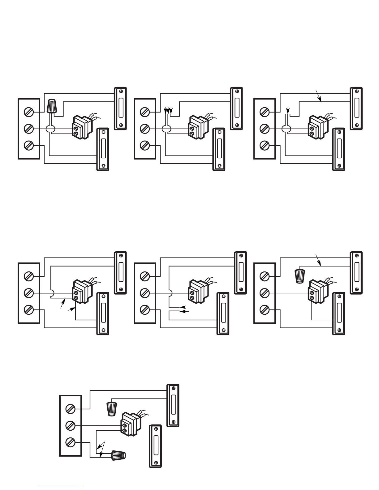
INTERCOM INSTALLATION OPTIONS
1. Label the FRONT and TRANS wires
connected to chime terminal screws.
Disconnect wires from chime and
remove chime.
2. Connect the two wires marked TRANS
to the Indoor Speaker’s RED wires.
3. Connect two wires marked FRONT to
the Indoor Speaker’s GREEN wires.
4. Disconnect FRONT pushbutton and
remove pushbutton. Connect two
front pushbutton wires to Outdoor
Speaker’s BROWN wires.
Note: The rear button wire can not be
used; therefore, the rear button will
not operate intercom. If rear button is
removed, fill hole with appropriate
material.
Installation for Front and Rear Door Pushbuttons–Common Wire Connection at Chime Location
After you identify the chime wiring, proceed with the corresponding installation step.
1. Label the two wires connected to the
TRANS and REAR chime terminals.
Label both wires TRANS.
2. Label FRONT wire connected to chime
terminal. Disconnect all wires from
chime and remove chime.
3. Since only one FRONT wire exists at
chime location, it will be necessary to
run at least one more standard
bell/chime from the Outdoor Speaker
location to the Indoor Speaker location.
Run wire and label it FRONT.
4. Connect two wires marked TRANS to
Indoor Speaker’s RED wires.
5. Connect two wires marked FRONT to
the Indoor Speaker’s GREEN wires.
6. Connect two wires at Outdoor
Speaker/pushbutton location to
Outdoor Speaker’s BROWN wires.
Installation for Front and Rear Door Pushbuttons–Common Wire Connection at Transformer Location
1. Label FRONT and TRANS wires
connected to the chime terminal
screws. Disconnect wires from
chime and remove chime.
2. Connect two wires marked TRANS to
Indoor Speaker’s RED wires.
3. Connect two wires marked FRONT to
Indoor Speaker’s GREEN wires.
4. Disconnect front pushbutton.
Connect two front pushbutton wires
to Outdoor Speaker’s BROWN wires.
Installation for Front Door Pushbutton Only–Common Wire Connection at Chime Location
1. Label the two wires connected to
TRANS and FRONT chime
terminals–label both wires TRANS.
2. Run a pair of standard bell/chime
wires from the Indoor location to the
Outdoor Speaker location. Label
wires DOOR.
3. Connect two wires marked TRANS to
Indoor Speaker’s RED wires.
4. Connect two wires marked DOOR to
the Indoor Speaker’s GREEN wires.
5. Connect wires at Outdoor Speaker
location to the Outdoor Speaker’s
BROWN wires.
Installation for Front Door Pushbutton Only–Common Wire Connection at Transformer
Chime
Front
Trans
Trans
Rear
Front
Front
Wires
Rear
Trans
Wire
Indoor
Speaker
Outdoor
Speaker
Trans
Green Wires Red Wires
Brown Wires
Trans
Wires
Chime
Front
Trans
Trans
Rear
Front
Front
Wire
Rear
Trans
Wire
Indoor
Speaker
Outdoor
Speaker
Trans
Red WiresGreen Wires
Brown Wires
Trans
Wires
Chime
Front
Trans
Trans
Rear
Front
Front
Wires
Trans
Wire
Indoor
Speaker
Outdoor
Speaker
Trans
Green Wires Red Wires
Brown Wires
Trans
Wires
Chime
Front
Trans
Trans
Rear
Front
Trans
Wire
Indoor
Speaker
Outdoor
Speaker
Trans
Red WiresGreen Wires
Brown Wires
Trans
Wires
16V
16V
Front
Wires
Front
Wires
Front
Wires
Front
Wires
16V
16V
16V
16V
16V
16V
120V AC
120V
AC
120V AC
120V
AC
120V AC
120V
AC
120V AC
120V
AC
Page 5

Figure 4
Outdoor Speaker
1. Once the Outdoor Speaker wiring is connected, the speaker
can be mounted.
2. Make sure speaker is mounted on a flat surface.
3. Use two screws (included) to mount speaker to surface. Use
wall anchors if necessary. See Figure 2.
4. Remove nameplate and namecard from Outdoor Speaker.
Write name on card and insert into nameplate. Snap
nameplate into place. See Figure 2.
Indoor Speaker
1. Once the Indoor Speaker wiring is connected,
the speaker can be mounted.
2. Attach pull cord if required. See Figure 3.
Insert cord through hole in TALK/LISTEN
button. Secure cord with knot.
3. Use two screws (included) to mount speaker
to wall. Use wall anchors if necessary. See
Figure 4.
Outdoor
Speaker
Nameplate
Namecard
Figure 2
Figure 3
Pull
Cord
Talk
Button
Indoor
Speaker
MOUNT THE SPEAKERS
TIMEOUT AND VOLUME ADJUSTMENTS
Figure 5
TIMEOUT
Thumbwheel
Figure 6
Volume
Adjustment
Access Hole
5
Timeout
The Outdoor Speaker operates “hands-free.”
The intercom conversation is controlled by the
Indoor Speaker. Operation is as follows: To
speak to the Outdoor Speaker, depress the
TALK button. To listen to the Outdoor Speaker,
release the TALK button.
When the TALK button is released, the Outdoor
Speaker will be active until it times out. This
timeout period is factory-set for 25 seconds.
If the owner desires a longer timeout period, it
can be adjusted up to 35 seconds. Adjust
timeout by turning TIMEOUT thumbwheel,
located inside on the circuit board, pot
clockwise to increase time. See Figure 5.
Volume
The volume is factory set. However, if the
intercom volume needs to be adjusted, use a
screwdriver through the hole in the bottom of
the speaker to make the adjustment. Turn
clockwise to INCREASE volume. See Figure 6.
Page 6

6
Indoor
Speaker
25701 Science Park Drive
Cleveland, Ohio 44122
www.lamson-home.com
Made in China
051205 IS183
LIMITED WARRANTY
The product you have purchased is guaranteed against defects in workmanship for the period
stated on the package. Warranties implied by law are subject to the same time period limitation.
Some states do not allow limitations on how long an implied warranty lasts, so this time limitation
may not apply to you.
If the product fails due to a manufacturing defect during normal use, return the product and dated
sales receipt to the store where purchased for replacement OR send the product and the dated
sales receipt to:
Lamson & Sessions
25701 Science Park Drive
Cleveland, OH 44122 USA
Attn: LHP Customer Service
Not Covered
- Batteries, light bulbs, and other expendable items are not covered by this warranty.
Repair service, adjustment and calibration due to misuse, abuse or negligence are not covered by
this warranty. Unauthorized service or modification of the product or of any furnished components
will void this warranty in its entirety. This warranty does not include reimbursement for
inconvenience, installation, set-up time, loss of use, postage, unauthorized service, or other
products used in conjunction with, but are not supplied by, Lamson & Sessions.
All requests for replacement must include a dated sales receipt (copies accepted). LAMSON &
SESSIONS IS NOT LIABLE FOR LOST PROFITS, INDIRECT, SPECIAL, EXEMPLARY, INCIDENTAL OR
CONSEQUENTIAL DAMAGES INCLUDING WITHOUT LIMITATION ANY SUCH DAMAGES DUE TO
IMPROPER WIRING OR MISUSE OF THE PRODUCT. As some states do not allow the exclusion or
limitation of incidental or consequential damages, the above limitation and exclusion may not
apply to you.
Master Speaker
Yellow
Wires
Orange
Wires
DH1201/DH1202
Pushbutton
Door
Strike
Wires
DH970
Door Strike
Figure 7
Figure 8
An optional Electric Door Strike feature can be added to the Intercom system.
This feature requires adding one DH1201 or DH1202 pushbutton and one
DH970 Door Strike–both sold separately.
Pushbutton Installation
1. Remove insert panel from Indoor Speaker. See Figure 7.
2. Insert the DH1201 or DH1202 through the pushbutton hole in the Indoor Speaker.
Note: Do not use lighted buttons.
Wiring Connections
1. Run standard bell/chime wire from Door Strike location to Indoor Speaker
location. See Figure 8.
2. Connect the two yellow wires from the Indoor Speaker’s PC board to the
pushbutton terminals.
3. Connect the Door Strike wires to the two orange wires on the Indoor
Speaker’s PC board.
Electric Door Strike Mounting
1. Mount Door Strike at the door latch according to the instructions included
with the Door Strike.
OPTIONAL ELECTRIC DOOR STRIKE WIRING
AND PUSHBUTTON INSTALLATION
Remove
Insert Panel
 Loading...