

Thomas & Betts COMFORT CRIMP SHURE STAKE ERG1802, COMFORT CRIMP SHURE STAKE ERG1806, COMFORT CRIMP SHURE STAKE ERG1804, COMFORT CRIMP SHURE STAKE ERG811, COMFORT CRIMP SHURE STAKE ERG1801 Operating Instructions Manual
Page 1
COMFORT CRIMP® SHURE STAKE
®
OPERATING INSTRUCTIONS
CAT. NOS. ERG811, ERG1801, ERG1802, ERG1804 & ERG1806
IMPORTANT: Read and understand all of the instructions and safety
information in this manual before operating or servicing this tool.
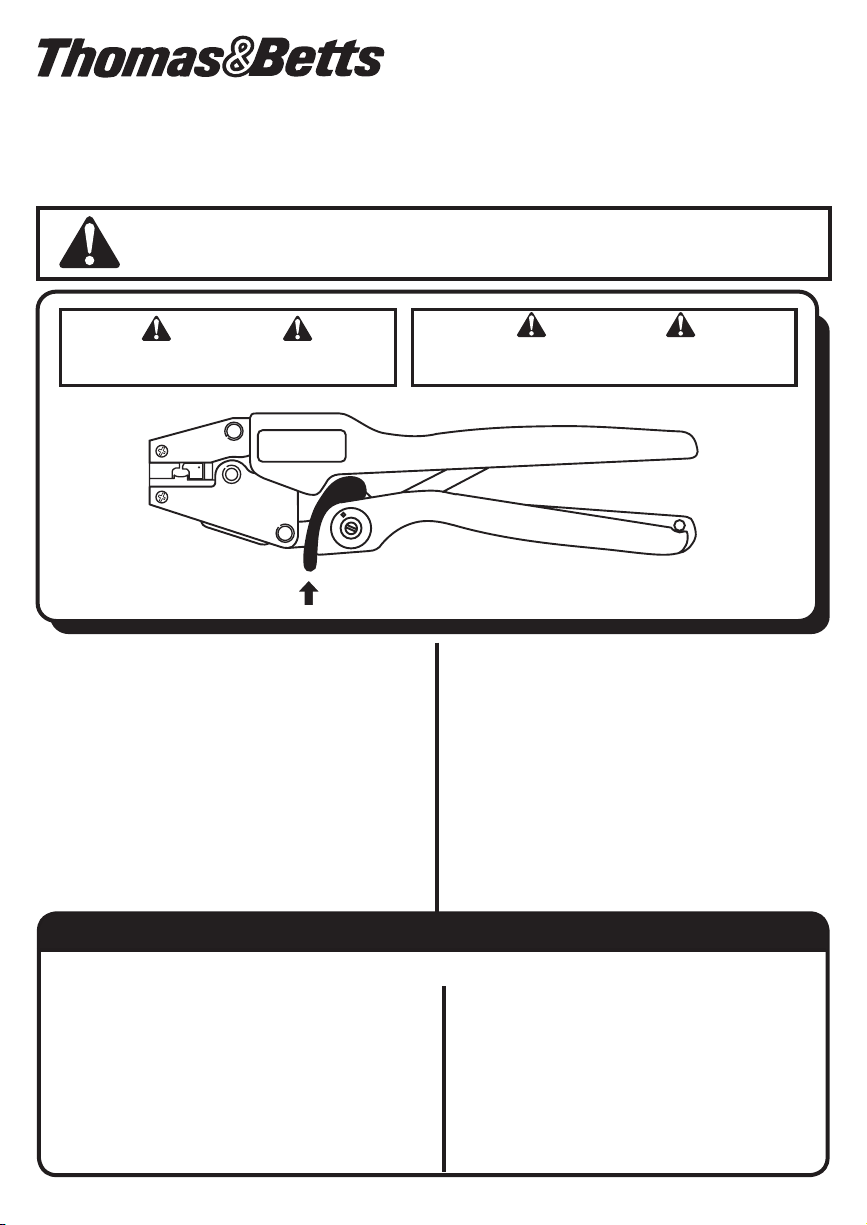
WARNING
KEEP ALL BODY PARTS AWAY FROM DIE NEST
DURING GAGING OR CRIMPING PROCEDURE.
To release the SHURE STAKE® mechanism, push up on
Figure 1
the release bar until the ratchet teeth are disengaged.
GENERAL SAFETY RULES:
1. FAMILIARIZE YOURSELF WITH THE TOOL. Read this Instruction
Sheet. Become aware of proper tool usage as well as the potential
hazards that could occur.
2.
DO NOT ABUSE TOOL.
reasonable care.
3. MAINTAIN TOOL WITH CARE. Keep tool in good condition at all
times. Keep it clean for proper performance.
4. KEEP WORK AREA CLEAN AND WELL LIT. Poor lighting and
cluttered area invite accidents.
5. USE SAFTEY GLASSES.
6. DO NOT OVER-REACH. Keep proper footing and balance at all times.
7.
NEVER ATTEMPT TO MAKE A CONNECTION TO A “HOT” LINE.
assume the power is OFF! Determine beforehand if any electrical
hazard could exist before making a connection to a line or wire.
Prevent damage by handling with
Never
WARNING
HANDLES ARE NON-INSULATING.
DO NOT CRIMP ON HOT ENERGIZED WIRES.
DESCRIPTION:
Each tool in a series, see Figure 1, is a hand operated crimping tool
utilizing non-interchangeable dies for installing certain Thomas & Betts
insulation piercing connectors on magnet wire. Incorporated in each
tool is a ratchet type SHURE STAKE
opening of the dies until a preset crimping pressure is reached, at
which point the handles can be released and the tool opened.
For certain wire combinations the dies will bottom (close), while for
others, because of the wire ll factor and type of wire, the dies will not
bottom. In order to produce an acceptable connection it is necessary
to operate the crimping tool with suitable hand pressure which is
controlled by the SHURE STAKE
checked periodically to ensure proper adjustment. This procedure is
described in succeeding paragraphs.
®
mechanism which prevents
®
mechanism. The tool should be
Operational Check & Maintenance
IMPORTANT: Crimped connector gaging should be checked regularly to insure that acceptable connections are being made.
OPERATION CHECK
1. Check operation of the tool periodically to insure its proper
adjustment. Continuous use of the tool will cause gradual wear of
movable parts. This in turn will cause the preset crimping pressure
to gradually decrease and the connector gaging to increase.
2. Once the connector gaging exceeds a specifi c value (based on the
size and type of wire), the connection will no longer be acceptable.
3. At this point, discontinue use of the tool.
4. To check the operation of the SHURE STAKE® mechanism and
connector gaging, a specifi c connector/wire combination should
be crimped and its gaging measured. (Refer to table 1, fi gure 3 and
fi gure 4, for specifi c wire combinations and only use copper.)
MAINTENANCE
1. Remove dust, moisture, and other contaminants with a clean
brush or a soft, lint-free cloth.
2. DO NOT use on objects that could damage the tool.
3. Make certain all pins, pivot points, and bearing surfaces are
protected with a THIN coat of any good SAE No. 20 motor oil.
DO NOT oil excessively.
4. Keep handles closed when not in use to prevent objects from
becoming lodged in the crimping dies.
TA02462 B Page 1 of 2
Page 2
1.0
INSTRUCTIONS FOR USE
1.1
1. Select proper connector to be installed on wire(s).
2. Select proper installing tool. (Refer to table 1).
3. Open tool handles fully.
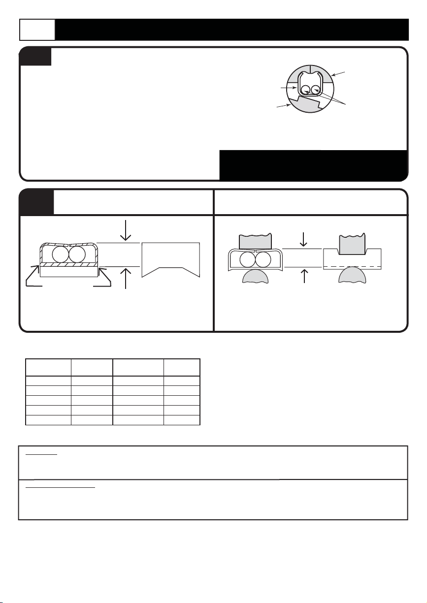
4. Position connector barrel in center of die nest with bottom
of barrel resting on die indentor, and open end of barrel
facing into die nest.
5. Insert wire(s) into the connector. Refer to connector instruction
sheet for proper wire arrangement.
6. Compress the connector by squeezing tool handles until the
SHURE STAKE® mechanism cycle has been completed.
Release handles to open tool.
7. Remove crimped connector from tool.
1.2
1. With a fi le, remove fl ash from connector edges.
2. Measure connector gaging with a standard micrometer. The
gaging surfaces of the connector are illustrated in Figure 3.
22L001, 22L002, 22L004
Series Connectors
GAGING
REMOVE FLASH
Figure 3
DIE NEST
CONNECTOR
DIE INDENTOR
WIRES
Figure 2
NOTE: For convenience, before placing wire(s) in the
connector, partially close the handles of the tool until
indentor die touches the connector.
22L006 Series Connectors
214420
GAGING
Measure connector gaging with a ball micrometer, or
equivalent, having a spindle diameter of 0.250. The gaging
surfaces of the connector are illustrated in Figure 4.
Figure 4
TABLE 1
Tool Connector
ERG-1801 22L001 (2) #24 Cu 0.068
ERG-1802 22L002 (2) #20 Cu 0.075
ERG-1804 22L004 (2) #32 Cu 0.033
ERG-1806 22L006 (1) #16 Cu 0.094
ERG-811 214420 (2) #20 Cu 0.103
WARRANTY: Thomas & Betts sells this product with the understanding that the user will perform all necessary tests to determine the suitability of this
product for the user’s intended application. Thomas & Betts warrants that this product will be free from defects in materials and workmanship for the
period stated on the enclosed warranty card. Upon prompt notifi cation of any warranted defect, Thomas & Betts will, at its option, repair or replace the
defective product or refund the purchase price. Proof of purchase is required. Misuse or unauthorized modifi cation of the product voids all warranties.
Limitations and Exclusions: THE ABOVE WARRANTY IS THE SOLE WARRANTY CONCERNING THIS PRODUCT, AND IS IN LIEU OF ALL OTHER
WARRANTIES EXPRESS OR IMPLIED, INCLUDING BUT NOT LIMITED TO ANY IMPLIED WARRANTY OF MERCHANTABILITY OR FITNESS FOR A
PARTICULAR PURPOSE, WHICH ARE SPECIFICALLY DISCLAIMED. LIABILITY FOR BREACH OF THE ABOVE WARRANTY IS LIMITED TO COST
OF REPAIR OR REPLACEMENT OF THE PRODUCT, AND UNDER NO CIRCUMSTANCES WILL THOMAS & BETTS BE LIABLE FOR ANY INDIRECT,
SPECIAL, INCIDENTAL OR CONSEQUENTIAL DAMAGES.
© 2008 Thomas & Betts. All Rights Reserved.
Series
Copper Wire
Combination
Maximum
Gaging
Thomas & Betts Corporation
Memphis, Tennessee
www.tnb.com
For parts, service, repair and
calibration, contact the Thomas & Betts
Tool Service Center at 1-800-284-TOOL (8665).
TA02462 B Page 2 of 2
 Loading...